EP2461059B1 - Roller bearing, cage segment, spacer, and main-shaft support structure for wind-driven generator - Google Patents
Roller bearing, cage segment, spacer, and main-shaft support structure for wind-driven generator Download PDFInfo
- Publication number
- EP2461059B1 EP2461059B1 EP12157148.3A EP12157148A EP2461059B1 EP 2461059 B1 EP2461059 B1 EP 2461059B1 EP 12157148 A EP12157148 A EP 12157148A EP 2461059 B1 EP2461059 B1 EP 2461059B1
- Authority
- EP
- European Patent Office
- Prior art keywords
- retainer
- roller bearing
- face
- spacer
- retainer segment
- Prior art date
- Legal status (The legal status is an assumption and is not a legal conclusion. Google has not performed a legal analysis and makes no representation as to the accuracy of the status listed.)
- Expired - Fee Related
Links
Images


Classifications
-
- F—MECHANICAL ENGINEERING; LIGHTING; HEATING; WEAPONS; BLASTING
- F03—MACHINES OR ENGINES FOR LIQUIDS; WIND, SPRING, OR WEIGHT MOTORS; PRODUCING MECHANICAL POWER OR A REACTIVE PROPULSIVE THRUST, NOT OTHERWISE PROVIDED FOR
- F03D—WIND MOTORS
- F03D15/00—Transmission of mechanical power
-
- F—MECHANICAL ENGINEERING; LIGHTING; HEATING; WEAPONS; BLASTING
- F16—ENGINEERING ELEMENTS AND UNITS; GENERAL MEASURES FOR PRODUCING AND MAINTAINING EFFECTIVE FUNCTIONING OF MACHINES OR INSTALLATIONS; THERMAL INSULATION IN GENERAL
- F16C—SHAFTS; FLEXIBLE SHAFTS; ELEMENTS OR CRANKSHAFT MECHANISMS; ROTARY BODIES OTHER THAN GEARING ELEMENTS; BEARINGS
- F16C33/00—Parts of bearings; Special methods for making bearings or parts thereof
- F16C33/30—Parts of ball or roller bearings
- F16C33/46—Cages for rollers or needles
- F16C33/51—Cages for rollers or needles formed of unconnected members
- F16C33/513—Cages for rollers or needles formed of unconnected members formed of arcuate segments for carrying one or more rollers
-
- F—MECHANICAL ENGINEERING; LIGHTING; HEATING; WEAPONS; BLASTING
- F03—MACHINES OR ENGINES FOR LIQUIDS; WIND, SPRING, OR WEIGHT MOTORS; PRODUCING MECHANICAL POWER OR A REACTIVE PROPULSIVE THRUST, NOT OTHERWISE PROVIDED FOR
- F03D—WIND MOTORS
- F03D80/00—Details, components or accessories not provided for in groups F03D1/00 - F03D17/00
- F03D80/70—Bearing or lubricating arrangements
-
- F—MECHANICAL ENGINEERING; LIGHTING; HEATING; WEAPONS; BLASTING
- F16—ENGINEERING ELEMENTS AND UNITS; GENERAL MEASURES FOR PRODUCING AND MAINTAINING EFFECTIVE FUNCTIONING OF MACHINES OR INSTALLATIONS; THERMAL INSULATION IN GENERAL
- F16C—SHAFTS; FLEXIBLE SHAFTS; ELEMENTS OR CRANKSHAFT MECHANISMS; ROTARY BODIES OTHER THAN GEARING ELEMENTS; BEARINGS
- F16C25/00—Bearings for exclusively rotary movement adjustable for wear or play
- F16C25/06—Ball or roller bearings
-
- F—MECHANICAL ENGINEERING; LIGHTING; HEATING; WEAPONS; BLASTING
- F16—ENGINEERING ELEMENTS AND UNITS; GENERAL MEASURES FOR PRODUCING AND MAINTAINING EFFECTIVE FUNCTIONING OF MACHINES OR INSTALLATIONS; THERMAL INSULATION IN GENERAL
- F16C—SHAFTS; FLEXIBLE SHAFTS; ELEMENTS OR CRANKSHAFT MECHANISMS; ROTARY BODIES OTHER THAN GEARING ELEMENTS; BEARINGS
- F16C33/00—Parts of bearings; Special methods for making bearings or parts thereof
- F16C33/30—Parts of ball or roller bearings
- F16C33/37—Loose spacing bodies
-
- F—MECHANICAL ENGINEERING; LIGHTING; HEATING; WEAPONS; BLASTING
- F16—ENGINEERING ELEMENTS AND UNITS; GENERAL MEASURES FOR PRODUCING AND MAINTAINING EFFECTIVE FUNCTIONING OF MACHINES OR INSTALLATIONS; THERMAL INSULATION IN GENERAL
- F16C—SHAFTS; FLEXIBLE SHAFTS; ELEMENTS OR CRANKSHAFT MECHANISMS; ROTARY BODIES OTHER THAN GEARING ELEMENTS; BEARINGS
- F16C33/00—Parts of bearings; Special methods for making bearings or parts thereof
- F16C33/30—Parts of ball or roller bearings
- F16C33/46—Cages for rollers or needles
- F16C33/467—Details of individual pockets, e.g. shape or roller retaining means
-
- F—MECHANICAL ENGINEERING; LIGHTING; HEATING; WEAPONS; BLASTING
- F16—ENGINEERING ELEMENTS AND UNITS; GENERAL MEASURES FOR PRODUCING AND MAINTAINING EFFECTIVE FUNCTIONING OF MACHINES OR INSTALLATIONS; THERMAL INSULATION IN GENERAL
- F16C—SHAFTS; FLEXIBLE SHAFTS; ELEMENTS OR CRANKSHAFT MECHANISMS; ROTARY BODIES OTHER THAN GEARING ELEMENTS; BEARINGS
- F16C33/00—Parts of bearings; Special methods for making bearings or parts thereof
- F16C33/30—Parts of ball or roller bearings
- F16C33/46—Cages for rollers or needles
- F16C33/4694—Single-split roller or needle cages
-
- F—MECHANICAL ENGINEERING; LIGHTING; HEATING; WEAPONS; BLASTING
- F16—ENGINEERING ELEMENTS AND UNITS; GENERAL MEASURES FOR PRODUCING AND MAINTAINING EFFECTIVE FUNCTIONING OF MACHINES OR INSTALLATIONS; THERMAL INSULATION IN GENERAL
- F16C—SHAFTS; FLEXIBLE SHAFTS; ELEMENTS OR CRANKSHAFT MECHANISMS; ROTARY BODIES OTHER THAN GEARING ELEMENTS; BEARINGS
- F16C33/00—Parts of bearings; Special methods for making bearings or parts thereof
- F16C33/30—Parts of ball or roller bearings
- F16C33/46—Cages for rollers or needles
- F16C33/54—Cages for rollers or needles made from wire, strips, or sheet metal
- F16C33/541—Details of individual pockets, e.g. shape or roller retaining means
-
- F—MECHANICAL ENGINEERING; LIGHTING; HEATING; WEAPONS; BLASTING
- F16—ENGINEERING ELEMENTS AND UNITS; GENERAL MEASURES FOR PRODUCING AND MAINTAINING EFFECTIVE FUNCTIONING OF MACHINES OR INSTALLATIONS; THERMAL INSULATION IN GENERAL
- F16C—SHAFTS; FLEXIBLE SHAFTS; ELEMENTS OR CRANKSHAFT MECHANISMS; ROTARY BODIES OTHER THAN GEARING ELEMENTS; BEARINGS
- F16C19/00—Bearings with rolling contact, for exclusively rotary movement
- F16C19/22—Bearings with rolling contact, for exclusively rotary movement with bearing rollers essentially of the same size in one or more circular rows, e.g. needle bearings
- F16C19/34—Bearings with rolling contact, for exclusively rotary movement with bearing rollers essentially of the same size in one or more circular rows, e.g. needle bearings for both radial and axial load
- F16C19/36—Bearings with rolling contact, for exclusively rotary movement with bearing rollers essentially of the same size in one or more circular rows, e.g. needle bearings for both radial and axial load with a single row of rollers
- F16C19/364—Bearings with rolling contact, for exclusively rotary movement with bearing rollers essentially of the same size in one or more circular rows, e.g. needle bearings for both radial and axial load with a single row of rollers with tapered rollers, i.e. rollers having essentially the shape of a truncated cone
-
- F—MECHANICAL ENGINEERING; LIGHTING; HEATING; WEAPONS; BLASTING
- F16—ENGINEERING ELEMENTS AND UNITS; GENERAL MEASURES FOR PRODUCING AND MAINTAINING EFFECTIVE FUNCTIONING OF MACHINES OR INSTALLATIONS; THERMAL INSULATION IN GENERAL
- F16C—SHAFTS; FLEXIBLE SHAFTS; ELEMENTS OR CRANKSHAFT MECHANISMS; ROTARY BODIES OTHER THAN GEARING ELEMENTS; BEARINGS
- F16C2300/00—Application independent of particular apparatuses
- F16C2300/10—Application independent of particular apparatuses related to size
- F16C2300/14—Large applications, e.g. bearings having an inner diameter exceeding 500 mm
-
- F—MECHANICAL ENGINEERING; LIGHTING; HEATING; WEAPONS; BLASTING
- F16—ENGINEERING ELEMENTS AND UNITS; GENERAL MEASURES FOR PRODUCING AND MAINTAINING EFFECTIVE FUNCTIONING OF MACHINES OR INSTALLATIONS; THERMAL INSULATION IN GENERAL
- F16C—SHAFTS; FLEXIBLE SHAFTS; ELEMENTS OR CRANKSHAFT MECHANISMS; ROTARY BODIES OTHER THAN GEARING ELEMENTS; BEARINGS
- F16C2360/00—Engines or pumps
- F16C2360/31—Wind motors
-
- Y—GENERAL TAGGING OF NEW TECHNOLOGICAL DEVELOPMENTS; GENERAL TAGGING OF CROSS-SECTIONAL TECHNOLOGIES SPANNING OVER SEVERAL SECTIONS OF THE IPC; TECHNICAL SUBJECTS COVERED BY FORMER USPC CROSS-REFERENCE ART COLLECTIONS [XRACs] AND DIGESTS
- Y02—TECHNOLOGIES OR APPLICATIONS FOR MITIGATION OR ADAPTATION AGAINST CLIMATE CHANGE
- Y02E—REDUCTION OF GREENHOUSE GAS [GHG] EMISSIONS, RELATED TO ENERGY GENERATION, TRANSMISSION OR DISTRIBUTION
- Y02E10/00—Energy generation through renewable energy sources
- Y02E10/70—Wind energy
- Y02E10/72—Wind turbines with rotation axis in wind direction
Definitions
- the present invention relates to a roller bearing, a retainer segment, a spacer and a main shaft structure of a wind-power generator, and more particularly to a large roller bearing, a retainer segment and a spacer contained in the large roller bearing, and a main shaft structure of a wind-power generator comprising the large roller bearing.
- a roller bearing comprises an outer ring, an inner ring, a plurality of rollers arranged between the outer ring and the inner ring, and a retainer retaining the plurality of rollers in general.
- the retainer retaining the rollers includes various kinds of retainers such as a resin retainer, a pressed retainer, a machined retainer, and a welded retainer based on a difference in material and production method, and they are used depending on their usage and characteristics.
- the retainer is an integrated type, that is, it comprises annular one component in general.
- roller bearing for supporting a main shaft of a wind-power generator provided with a blade for receiving the wind
- the roller bearing since it needs to receive a high load, the roller bearing becomes also large. It means that each component member constituting the roller bearing such as a roller and a retainer becomes large, so that it becomes difficult to produce and assemble the member. In this case, when each member can be split, its production and assembling become easy.
- Fig. 36 is a perspective view showing a retainer segment of the split type retainer disclosed in the European Patent Publication No. 1408248A2 . Referring to Fig.
- a retainer segment 101a has column parts 103a, 103b, 103c, 103d and 103e extending in a direction along a shaft so as to form a plurality of pockets 104 to hold rollers, and connection parts 102a and 102b extending in a circumferential direction so as to connect the plurality of column parts 103a to 103e.
- Fig. 37 is a sectional view showing a part of the roller bearing containing the retainer segment 101a shown in Fig. 36 .
- the roller bearing 111 has an outer ring 112, an inner ring 113, a plurality of rollers 114, and the plurality of retainer segments 101a, 101b, 101c and the like.
- the plurality of rollers 114 are held by the plurality of retainer segments 101a and the like in the vicinity of a PCD (Pitch Circle Diameter) in which the rollers roll most stably.
- PCD Peak Circle Diameter
- the retainer segment 101a holding the plurality of rollers 114 is arranged circumferentially so as to abut on the adjacent retainer segments 101b and 101c having the same configuration at its column parts 103a and 103e positioned on the circumferentially most outer side.
- the plurality of retainer segments 101a, 101b, 101c and the like are continuously lined with each other and incorporated in the roller bearing 111, whereby one annular retainer contained in the roller bearing 111 is formed.
- the above one annular retainer is formed by lining the plurality of retainer segments continuously in the circumferential direction.
- a circumferential gap in view of thermal expansion and the like is needed.
- the adjacent retainer segments collide against each other in the circumferential direction when the roller bearing is operated.
- the column part positioned at the end receives the circumferential load from the adjacent retainer segment and it is deformed.
- Fig. 38 is a view showing the vicinity of the column part 103a positioned at one end of the retainer segment 101a incorporated in the roller bearing, taken from the radial outer side, that is, from a direction shown by an arrow X in Fig. 37 .
- the deformation of the column part 103a is shown with exaggeration in Fig. 38 .
- the retainer segment 101a receives the load from the circumferential direction, that is, from the direction shown by arrows Y in Figs. 37 and 38 due to the collision against the adjacent retainer segment 101b.
- the load from the retainer segment 101b is applied to the column part 103a positioned at the circumferential end in the retainer segment 101a. Since the column part 103a is not connected in the circumferential direction and vulnerable to the circumferential load, it is deformed to the side of the pocket 104. In this case, the circumferential inner side of the column part 103a, that is, an end face 109 of the pocket 104 enters the pocket 104. As a result, the roller could be locked and the retainer segment 101 could be damaged due to the abrasion of the column part 103a.
- a roller bearing comprises an outer ring, an inner ring, a plurality of rollers arranged between the outer ring and the inner ring, and a plurality of retainer segments having a plurality of column parts extending in a direction along a shaft so as to form a pocket for holding the roller, and a connection part extending in a circumferential direction so as to connect the plurality of column parts, and continuously lined with each other in the circumferential direction between the outer ring and the inner ring, in which a corner of a circumferential end face is chamfered.
- the retainer segment is prevented from hitting against an edge.
- the contact surface pressure with the adjacent retainer segment can be lowered and the friction and abrasion between them can be reduced. Therefore, the retainer segment is hardly damaged.
- the chamfered part is provided at a radial corner of the end face. According to the above constitution, when the retainer segment is inclined in the radial direction especially, the adjacent retainer segment can be prevented from hitting against an edge of the radial corner.
- the end face expands in the circumferential direction from its corner to its center. According to the above constitution, even when the retainer segment is inclined, the expansion part in the center of the circumferential end face comes in contact with the adjacent retainer segment. Thus, the contact surface pressure with the adjacent retainer segment can be further lowered and the friction and the abrasion between them can be further reduced.
- the end face is provided with a crowning.
- the contact surface pressure with the adjacent retainer segment can be further lowered and the friction and the abrasion between them can be further reduced.
- a spacer arranged between the circumferentially arranged first retainer segment and last retainer segment and having a chamfered part at a corner of a circumferential spacer end face is provided.
- the spacer for adjusting the gap is arranged in some cases. Since the spacer is an independent member, when it is inclined in the radial direction or the axial direction and comes in contact with the adjacent retainer segment at the corner of the circumferential spacer end face, it could hit against an edge. However, in the case where the spacer is provided with the chamfered part at the corner of the circumferential spacer end face, even when the spacer is inclined, it can be prevented from hitting against the edge at the circumferential corner of the spacer. Thus, the contact surface pressure with the adjacent retainer segment can be reduced and the friction and abrasion between them can be reduced.
- a retainer segment is provided by splitting one annular retainer along a split line extending in a direction along a shaft so as to have at least one pocket for housing a roller.
- the retainer segment has a plurality of column parts extending in the direction along the shaft so as to form the pocket for holding the roller, and a connection part extending in a circumferential direction so as to connect the plurality of column parts, in which a chamfered part is provided at a corner of a circumferential end face.
- the chamfered part provided at the corner of the end face is in contact with the adjacent retainer segment, it is prevented from hitting against an edge.
- the contact surface pressure with the adjacent retainer segment can be reduced and the friction and abrasion between them can be reduced.
- a spacer is arranged between the circumferentially arranged first retainer segment and last retainer segment.
- a chamfered part is provided at a corner of a circumferential spacer end face.
- the chamfered part provided at the corner of the end face comes in contact with the adjacent retainer segment, the adjacent retainer segment can be prevented from hitting against an edge.
- the contact surface pressure with the adjacent retainer segment can be reduced and the friction and abrasion between them can be reduced.
- a main shaft support structure of a wind-power generator comprises a blade receiving wind power, a main shaft having one end fixed to the blade and rotating together with the blade, and a roller bearing incorporated in a fixing member and supporting the main shaft rotatably.
- the roller bearing comprises an outer ring, an inner ring, a plurality of rollers arranged between the outer ring and the inner ring, and a plurality of retainer segments having a plurality of column parts extending in a direction along the shaft so as to form a pocket for holding the roller, and a connection part extending in a circumferential direction so as to connect the plurality of column parts, and continuously lined with each other in the circumferential direction between the outer ring and the inner ring, in which a chamfered part is provided at a corner of a circumferential end face.
- the above main shaft structure of the wind-power generator contains the roller bearing in which the retainer segment is hardly damaged, it can implement a long life.
- the retainer segment is inclined in the radial direction or the axial direction in the roller bearing, since the corner of the circumferential end face is chamfered, the chamfered part comes in contact with the adjacent retainer segment.
- the contact surface pressure with the adjacent retainer segment can be lowered and the friction and abrasion between them can be reduced. Therefore, the retainer segment is hardly damaged.
- the chamfered part provided at the corner of the end face is in contact with the adjacent retainer segment, it is prevented from hitting against an edge.
- the contact surface pressure with the adjacent retainer segment can be reduced and the friction and abrasion between them can be reduced.
- the chamfered part provided at the corner of the end face comes in contact with the adjacent retainer segment, it can be prevented from hitting against an edge.
- the contact surface pressure with the adjacent retainer segment can be reduced and the friction and abrasion between them can be reduced.
- the above main shaft structure of the wind-power generator contains the roller bearing in which the retainer segment is hardly damaged, it can implement a long life.
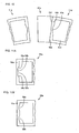
- Fig. 23 is a perspective view showing a retainer segment 11q contained in the tapered roller bearing according to the present invention.
- Fig. 24 is a sectional view showing the retainer segment 11q shown in Fig. 23 cut by a plane containing a line XXIV-XXIV in Fig. 23 and intersecting with a shaft.
- Fig 25 is a sectional view showing the retainer segment 11q shown in Fig. 23 cut by a plane passing through the center of a column part 14q and intersecting with a circumferential direction.
- a chamfered part and a crowning part are shown with exaggeration and a plurality of tapered rollers 12q, 12r and 12s held by the retainer segment 11q are shown by dotted lines in Figs. 24 and 25 .
- a PCD 22q is shown by a dashed line.
- the retainer segment 11q is provided by splitting one annular retainer along a split line extending in an axial direction so as to have at least one pocket for holding the roller.
- the retainer segment 11q contains four column parts 14q, 14r, 14s and 14t extending in the axial direction so as to form pockets 13q, 13r and 13s for holding the tapered rollers 12q, 12r and 12s, a pair of connection parts 15q and 15r extending in the circumferential direction so as to connect the four column parts 14q to 14t, and a pair of projections 16q and 16r projecting in the circumferential direction.
- connection parts 15q and 15r and the pair of projections 16q and 16r have predetermined curvature radiuses in the circumferential direction so as to form the one annular retainer in the circumferential direction when the plurality of retainer segments 11q and the like are incorporated in the tapered roller bearing.
- the curvature radiuses of the connection part 15q and the projection 16q positioned on the small diameter side of the tapered rollers 12q to 12s are designed to be smaller than the curvature radiuses of the connection part 15r and the projection 16r positioned on the large diameter side of the tapered rollers 12q to 12s, among the pair of connection parts 15q and 15r and the pair of projections 16q and 16r.
- Guide surfaces 17q, 17r, 17s, 17t, 18q, 18r, 18s and 18t are provided on the inner diameter side and the outer diameter side of the column parts 14q to 14t positioned on circumferential both sides of the pockets 13q to 13s. According to the above constitution, the retainer segment is guided by the rollers and the radial movement of the retainer segment 11q can be regulated. Oil grooves 19q and 20q are provided at the axial center of the column parts 14q to 14t such that they are recessed from the outer diameter side and the inner diameter side toward the radial inner side and outer side, respectively and penetrate in the circumferential direction. The oil grooves 19q and 20q implement the preferable circulation of a lubricant agent.
- Fig. 26A is a view showing the end face 21q taken from the axial direction, that is, taken from the direction shown by an arrow XXVI in Fig. 23 .
- Fig. 27A is a view showing the end face 21q taken from the radial direction, that is, taken from the direction of an arrow XXVII ring in Fig. 23 .
- a radial corner 23q of the end face 21q is chamfered.
- an axial corner 23r of the end face 21q is also chamfered.
- a full crowning is provided in the end face 21q in the radial direction and axial direction. That is, the end face 21q expands in the circumferential direction from the radial and axial corners 23q and 23r toward the radial and axial center.
- the circumferential end face 21r positioned on the large diameter side of the tapered rollers 12q to 12s has the same configuration as that of the end face 21q, its description will be omitted.
- Fig. 28 is a perspective view showing a spacer 26q contained in the tapered roller bearing. Referring to Fig. 28 , the constitution of the spacer 26q will be described.
- the spacer 26q includes end parts 27q and 27r positioned at axial both ends, and a center part 28q positioned between the end parts 27q and 27r.
- the axial distance between the end parts 27q and 27r is the same as the axial distance between the pair of projections 16q and 16r contained in the above retainer segment 11q.
- oil grooves 30q and 30r penetrating in the circumferential direction are provided on the inner diameter surface side and the outer diameter surface side of the center part 28q.
- a radial corner 25q of the spacer end face 29q is chamfered.
- the axial corner 25r of the spacer end face 29q is also chamfered.
- a full crowning is provided in the spacer end face 29q in the radial direction and the axial direction. That is, the spacer end face 29q has a configuration expanding in the circumferential direction from the radial and axial corners 25q and 25r toward the radial and axial center.
- a circumferential spacer end face 29r of the end part 27r of the spacer 26q has the same configuration as that of the spacer end face 29q, its description will be omitted.
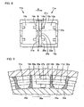
- Fig. 29 is a schematic sectional view showing the tapered roller bearing 31q in which the plurality of retainer segments 11q, 11r, 11s and 11t and the spacer 26q are arranged in the circumferential direction, taken from the axial direction.
- Fig. 30 is an enlarged sectional view at a part XXX in Fig. 29 .
- the retainer segments 11r, 11s and 11t have the same configuration as that of the retainer segment 11q, their description will be omitted.
- a tapered roller 34q held by the retainer segment 11q is not shown in Fig. 29 .
- the retainer segment arranged first is the retainer segment 11q and the retainer segment arranged last is the retainer segment 11t among the plurality of retainer segments 11q to 11t.
- a tapered roller bearing 31q comprises an outer ring 32q, an inner ring 33q, the plurality of retainer segments 11q to 11t, and the spacer 26q.
- the retainer segments 11q to 11t are continuously arranged in the circumferential direction.
- the retainer segment 11q is arranged first, and then the retainer segment 11r is arranged so as to abut on the retainer segment 11q.
- the retainer segment 11s is arranged so as to abut on the retainer segment 11r and the retainer segment is continuously arranged and finally the retainer segment 11t is arranged.
- the tapered rollers 34q are arranged in pockets (35q) formed between the two adjacent retainer segments 11q and 11r and the like except for the space between the first retainer segment 11q and the last retainer segment 11t.
- the circumferential end face 21q of the retainer segment 11q abuts on an end face 21s of the adjacent retainer segment 11r.
- the end face 21s of the adjacent retainer segment 11r comes in contact with the chamfered part of the corner 23q.
- the end face 21s of the adjacent retainer segment 11r can be prevented from hitting against an edge. Therefore, when the retainer segment 11q comes in contact with the retainer segment 11r, contact surface pressure can be low, so that the friction and abrasion between the retainer segments 11q and 11r can be reduced.
- the end face 21r of the retainer segment 11q positioned on the large diameter side of the tapered roller 34q can be prevented from hitting against an edge when it is in contact with the adjacent retainer segment 11r.
- the end faces 21q to 21u of the retainer segments 11q to 11s can be prevented from hitting against the edges.
- the contact surface pressures between the retainer segments 11q to 11s can be lowered and the friction and abrasion can be reduced.
- the retainer segments 11q to 11s can be prevented from being damaged.
- the full crowning is provided in the end faces 21q and 21r in the radial and axial directions, so that the end face 21s of the adjacent retainer segment 11r abuts on the crowning part, so that the contact surface pressure can be further lowered, and the friction and the abrasion can be further reduced.
- Figs. 26B and 26C are views showing an end face 41q contained in the retainer segment 11q according to another embodiment of the present invention taken in the radial direction.
- Figs. 27B and 27C are views showing the parts corresponding to Figs. 26B and 26C , respectively, taken from the axial direction.
- the configuration of the end face 41q may be a cut crowning in which radial and axial corners 42q and 44q are cut at sharp angles with respect to an outer diameter surface 43q, an inner diameter surface 43r and an axial width surface 45q.
- the configuration of an end face 46q may be such that radial axial corners 47q and 48q may be R-chamfered.
- a partial crowning may be provided in the end faces 41q and 46q.
- Such end faces 41q and 46q have a configuration expanding from the corners 42q, 44q, 47q and 48q toward the center, so that the contact surface pressure can be lowered and the friction and the abrasion can be reduced when they are in contact with the adjacent retainer segment 11r.
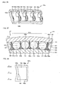
- Fig. 31 is an enlarged sectional view showing a part XXXI in Fig. 29 .
- Fig. 32 is a schematic view showing the part shown in Fig. 31 taken from the radial outer side, that is, from the side of the outer ring 32q. Referring to Figs. 31 and 32 , the retainer segments 11q and the like are continuously arranged so as to abut on each other, and the spacer 26q is arranged between a gap 39q between the retainer segment 11q and the retainer segment 11t.
- the last gap means a maximum gap between the first retainer segment 11q and the spacer 26q arranged between the first retainer segment 11q and the last retainer segment 11t when the retainer segments 11q to 11t are arranged circumferentially without leaving any gap and the last retainer segment 11t and the spacer 26q are arranged without leaving any gap.
- the circumferential spacer end face 29q of the spacer 26q abuts on the end faces 21q and 21v of the adjacent retainer segments 11q and 11t.
- the end faces 21q and 21v of the adjacent retainer segments 11q and 11t abut on the chamfered part of the corner 25q, edge hitting can be prevented.
- the contact surface pressure with the adjacent retainer segments 11q and 11t can be lowered, and the friction and abrasion with the retainer segments 11q and 11t can be reduced.
- the spacer end face 29r positioned on the large diameter side of the tapered roller 34q can be prevented from hitting against an edge when it is in contact with the adjacent retainer segments 11q and 11t. Therefore, the contact surface pressure thereof can be lowered and the friction and abrasion thereof can be reduced. As a result, the adjacent retainer segments 11q and 11t can be prevented from being damaged.
- the corners 23q and 23s of the end faces 21q, 21r, 21v and 21w of the retainer segments 11q and 11t adjacent to the spacer 26q are also chamfered, even when the retainer segments 11q and 11t are inclined, the spacer end faces 29q and 29r can be prevented from hitting against an edge. Therefore, the contact surface pressure of the spacer 26q can be lowered and the friction and abrasion of the spacer 26q can be reduced. As a result, the spacer 26q can be prevented from being damaged.
- the spacer 26q abuts on the adjacent retainer segments 11q and 11t at the part where the crowning is provided, so that the contact surface pressure can be further lowered, and the friction and the abrasion can be further reduced.
- each of the retainer segments 11q to 11t has the projections 16q and 16r projecting in the circumferential direction in the above embodiment
- the present invention is not limited to this and may be applied to a retainer segment having no projection 16q or 16r, that is, having a constitution in which a column part is arranged on the circumferential outer side.
- Figs. 33A and 33B are sectional views showing a part of the retainer segment in this case.
- a retainer segment 51q comprises a column part 52q positioned on the circumferential outer side, and a connection part 53q connecting the column part 52q.
- a corner 55q of a circumferential end face 54q of the column part 52q is chamfered.
- a full crowning is provided in the end face 54q such that it expands in the circumferential direction from the corners 55q of the end face 54q to the center. In this configuration, edge hitting can be prevented at the contact with the adjacent retainer segment.
- a corner 59q of an end face 58q of a column part 57q provided in a retainer segment 56q may be chamfered and a cut crowning cut at a sharp angle may be provided.
- Figs. 34 and 35 show one example of a main shaft support structure of a wind-power generator in which the roller bearing according to one embodiment of the present invention is used as a main shaft support bearing 75.
- a casing 73 of a nacelle 72 for supporting the main part of the main shaft support structure is put on a support table 70 through a slewing bearing 71 at a high position so as to be horizontally turned.
- a blade 77 receiving wind power is fixed to one end of a main shaft 76.
- the main shaft 76 is rotatably supported in the casing 73 of the nacelle 72 through the main shaft support bearing 75 incorporated in a bearing housing 74, and the other end of the main shaft 76 is connected to a speed-up gear 78, and an output shaft of the speed-up gear 78 is coupled to a rotor shaft of a generator 79.
- the nacelle 72 is turned at any angle by a rotation motor 80 through a speed-down gear 81.
- the main shaft support bearing 75 incorporated in the bearing housing 74 is the roller bearing according to one embodiment of the present invention comprising the outer ring, the inner ring, the plurality of rollers arranged between the outer ring and the inner ring, and the plurality of retainer segments having the plurality of column parts extending in a direction along the shaft so as to form a pocket for holding the roller, and the plurality of connection parts extending in the circumferential direction so as to connect the plurality of column parts, and continuously lined with each other in the circumferential direction between the outer ring and the inner ring.
- the column part is positioned at circumferential each end of the retainer segment.
- the circumferential outer side end face of the column part positioned at each end is flat, and the circumferential inner side end face of the column part positioned at the end is provided with the recess recessed in the circumferential direction so as to reduce the thickness of the column part.
- the main shaft support bearing 75 supports the main shaft 76 whose one end is fixed to the blade 77 receiving great wind power, it receives a high load.
- the roller can be prevented from being locked and the column part can be prevented from being damaged.
- the roller bearing has a long life and the main shaft support structure of the wind-power generator implements long life.
- the main shaft support bearing 75 incorporated in the bearing housing 74 is the roller bearing according to still another embodiment of the present invention comprising the outer ring, the inner ring, the plurality of rollers arranged between the outer ring and the inner ring, and the plurality of retainer segments having the plurality of column parts extending in the direction along the shaft so as to form the pocket for holding the roller and the plurality of connection parts extending in the circumferential direction so as to connect the plurality of column parts and continuously lined with each other in the circumferential direction between the outer ring and the inner ring.
- the column part is positioned at circumferential each end of the retainer segment.
- the expansion part expanding in the circumferential direction is provided on the circumferential outer side of the column part positioned at the end, and the recess recessed in the circumferential direction so as to reduce the thickness of the column part is provided on the circumferential inner side thereof.
- the main shaft support bearing 75 supports the main shaft 76 whose one end is fixed to the blade 77 receiving great wind power, it receives a high load.
- the retainer segment can be prevented from being damaged.
- the roller bearing has a long life and the main shaft support structure of the wind-power generator implements long life.
- the main shaft support bearing 75 incorporated in the bearing housing 74 is the roller bearing according to still another embodiment of the present invention, and the roller bearing comprises the outer ring, the inner ring, the plurality of rollers arranged between the outer ring and the inner ring, and the plurality of retainer segments having the plurality of column parts extending in the direction along the shaft so as to form the pocket for holding the roller and the plurality of connection parts extending in the circumferential direction so as to connect the plurality of column parts and continuously lined with each other in the circumferential direction between the outer ring and the inner ring, in which the corner of the circumferential end face is chamfered.
- the main shaft support bearing 75 supports the main shaft 76 whose one end is fixed to the blade 77 receiving great wind power, it receives a high load. Thus, the main shaft support bearing 75 has to be large itself.
- each retainer segment is an independent member, it is likely that the retainer segment is inclined and it is in contact with the adjacent retainer segment at their edges.
- edge hitting can be prevented. Therefore, the retainer segment is prevented from being damaged, and the main shaft support structure of the wind-power generator implements a long life.
- the retainer segment has three pockets for holding the rollers in the figures, the present invention is not limited to this and a retainer segment may have four or more pockets. According to such retainer segment, since it has many pockets provided with the guide surface, it can be arranged in the radial direction more stably.
- the tapered roller is used as the roller provided in the roller bearing in the above embodiment, the present invention is not limited to this, a cylindrical roller, a needle roller, and a long roller may be used.
- circumferential and axial corners of the end face of the retainer segment are chamfered in the above embodiment, the present invention is not limited to this, and any one of the corners may be chamfered.
- the tapered roller bearing comprises the spacer in the above embodiment
- the present invention is not limited to this and it can be applied to a tapered roller bearing having no spacer.
- the configuration of the spacer may be a roughly rectangular solid or a configuration in which the center is expanded in the circumferential direction.
- the roller may not be arranged between the adjacent retainer segments, or the roller may be arranged between the spacer and the retainer segment.
- roller bearing and the retainer segment in the present invention since the roller can be prevented from being locked and the column part can be prevented from being damaged, they can be effectively applied to a roller bearing in which smooth roller rolling is required.
- the retainer segment and the spacer in the present invention since the retainer segment can be prevented from being damaged, they can be effectively applied to a roller bearing in which a long life is required and a retainer segment and a spacer used in such roller bearing.
- the main shaft support structure of the wind-power generator in the present invention it can be effectively applied to a main shaft support structure of a wind-power generator in which a long life is required.
Landscapes
- Engineering & Computer Science (AREA)
- General Engineering & Computer Science (AREA)
- Mechanical Engineering (AREA)
- Life Sciences & Earth Sciences (AREA)
- Sustainable Development (AREA)
- Sustainable Energy (AREA)
- Chemical & Material Sciences (AREA)
- Combustion & Propulsion (AREA)
- Rolling Contact Bearings (AREA)
- Wind Motors (AREA)
Applications Claiming Priority (4)
| Application Number | Priority Date | Filing Date | Title |
|---|---|---|---|
| JP2006066175A JP4177852B2 (ja) | 2006-03-10 | 2006-03-10 | 風力発電機の主軸支持用ころ軸受、保持器セグメント、および風力発電機の主軸支持構造 |
| JP2006066176A JP2007239950A (ja) | 2006-03-10 | 2006-03-10 | ころ軸受、保持器セグメントおよび風力発電機の主軸支持構造 |
| JP2006068294A JP4063847B2 (ja) | 2006-03-13 | 2006-03-13 | ころ軸受、保持器セグメントおよび風力発電機の主軸支持構造 |
| EP07737398A EP2065604A4 (en) | 2006-03-10 | 2007-02-26 | BALL BEARINGS, CAGE SEGMENT, SPACERS AND MAIN WAVE STRUCTURE FOR WIND-DRIVEN GENERATOR |
Related Parent Applications (2)
| Application Number | Title | Priority Date | Filing Date |
|---|---|---|---|
| EP07737398.3 Division | 2007-02-26 | ||
| EP07737398A Division EP2065604A4 (en) | 2006-03-10 | 2007-02-26 | BALL BEARINGS, CAGE SEGMENT, SPACERS AND MAIN WAVE STRUCTURE FOR WIND-DRIVEN GENERATOR |
Publications (2)
| Publication Number | Publication Date |
|---|---|
| EP2461059A1 EP2461059A1 (en) | 2012-06-06 |
| EP2461059B1 true EP2461059B1 (en) | 2015-04-08 |
Family
ID=38509312
Family Applications (3)
| Application Number | Title | Priority Date | Filing Date |
|---|---|---|---|
| EP07737398A Withdrawn EP2065604A4 (en) | 2006-03-10 | 2007-02-26 | BALL BEARINGS, CAGE SEGMENT, SPACERS AND MAIN WAVE STRUCTURE FOR WIND-DRIVEN GENERATOR |
| EP12157146.7A Expired - Fee Related EP2461058B1 (en) | 2006-03-10 | 2007-02-26 | Roller bearing, cage segment and main-shaft support structure for wind-driven generator |
| EP12157148.3A Expired - Fee Related EP2461059B1 (en) | 2006-03-10 | 2007-02-26 | Roller bearing, cage segment, spacer, and main-shaft support structure for wind-driven generator |
Family Applications Before (2)
| Application Number | Title | Priority Date | Filing Date |
|---|---|---|---|
| EP07737398A Withdrawn EP2065604A4 (en) | 2006-03-10 | 2007-02-26 | BALL BEARINGS, CAGE SEGMENT, SPACERS AND MAIN WAVE STRUCTURE FOR WIND-DRIVEN GENERATOR |
| EP12157146.7A Expired - Fee Related EP2461058B1 (en) | 2006-03-10 | 2007-02-26 | Roller bearing, cage segment and main-shaft support structure for wind-driven generator |
Country Status (6)
| Country | Link |
|---|---|
| US (4) | US20090046974A1 (zh) |
| EP (3) | EP2065604A4 (zh) |
| CN (4) | CN102748381B (zh) |
| DK (2) | DK2461059T3 (zh) |
| ES (2) | ES2541409T3 (zh) |
| WO (1) | WO2007105476A1 (zh) |
Cited By (1)
| Publication number | Priority date | Publication date | Assignee | Title |
|---|---|---|---|---|
| TWI619896B (zh) * | 2015-07-03 | 2018-04-01 | Nidec Shimpo Corp | Bearing and reducer |
Families Citing this family (29)
| Publication number | Priority date | Publication date | Assignee | Title |
|---|---|---|---|---|
| JP5565101B2 (ja) * | 2010-05-27 | 2014-08-06 | 株式会社ジェイテクト | ころ軸受 |
| DE102010056059A1 (de) * | 2010-12-23 | 2012-06-28 | Schaeffler Technologies Gmbh & Co. Kg | Wälzlagerkäfig und Wälzlager |
| WO2012092107A2 (en) | 2010-12-27 | 2012-07-05 | The Timken Company | Segmented bearing retainer for wire support rings |
| KR20140027977A (ko) * | 2011-05-13 | 2014-03-07 | 아크티에볼라게트 에스케이에프 | 풍력발전용 터빈에 사용되는 롤링 베어링용 스페이서 |
| BR112013028181A8 (pt) | 2011-05-13 | 2021-04-27 | Skf Ab | espaçador para mancal de rolamento, mancal de rolamento e uso de um mancal de rolamento |
| WO2013005771A1 (ja) * | 2011-07-07 | 2013-01-10 | Ntn株式会社 | 転がり軸受 |
| US20130084034A1 (en) * | 2011-10-03 | 2013-04-04 | Schaeffler Technologies AG & Co. KG | Bearing with high-load radial and axial capabilites including a thermal compensation element as needed |
| JP2013122257A (ja) * | 2011-12-09 | 2013-06-20 | Ntn Corp | ころ軸受 |
| EP2628968B1 (en) * | 2012-02-16 | 2019-06-12 | Aktiebolaget SKF | Loose spacing body forming an open pocket to accomodate two rollers, in particular for a thrust roller bearing of a tunnel boring machine |
| DE102012207529A1 (de) * | 2012-05-07 | 2013-11-07 | Aktiebolaget Skf | Käfigsegment eines Kegelrollenlagers und Kegelrollenlager |
| JP2013238295A (ja) * | 2012-05-16 | 2013-11-28 | Jtekt Corp | 転がり軸受 |
| JP2013242018A (ja) * | 2012-05-22 | 2013-12-05 | Jtekt Corp | 転がり軸受用の分割保持器及びそれを用いた転がり軸受 |
| EP2855954B1 (en) | 2012-06-01 | 2017-05-10 | The Timken Company | Improved segmented bearing retainer |
| JP2014020393A (ja) * | 2012-07-12 | 2014-02-03 | Jtekt Corp | 分割保持器用の治具及び転がり軸受の組み立て方法 |
| EP2792893B1 (en) | 2013-04-19 | 2016-02-10 | Aktiebolaget SKF | Cage with parallel pockets for rolling bearing |
| DE102013207301A1 (de) * | 2013-04-23 | 2014-10-23 | Schaeffler Technologies Gmbh & Co. Kg | Wälzkörperführungselement, insbesondere für ein Kegelrollen-Großwälzlager |
| FR3006397B1 (fr) | 2013-06-03 | 2015-10-16 | Ntn Snr Roulements | Cage segmentee pour unite de roulement. |
| CN105980724B (zh) * | 2014-02-07 | 2019-09-03 | 株式会社捷太格特 | 分割保持器和滚子轴承 |
| DE102015201170B4 (de) | 2015-01-23 | 2018-05-17 | Aktiebolaget Skf | Wälzlagerkäfig |
| DE102015206533A1 (de) * | 2015-04-13 | 2016-10-13 | Schaeffler Technologies AG & Co. KG | Käfigsegment eines Käfigs eines Wälzlagers und Käfig eines Wälzlagers |
| US10415429B2 (en) * | 2015-09-25 | 2019-09-17 | General Electric Company | Planet gearbox with cylindrical roller bearing with high density roller packing |
| DE102016207034A1 (de) * | 2016-04-26 | 2017-10-26 | Schaeffler Technologies AG & Co. KG | Käfigsegment eines Zylinderrollenlagers |
| US10054163B2 (en) * | 2016-11-15 | 2018-08-21 | General Electric Company | Bearing cages for roller bearing assemblies |
| CN110382891B (zh) * | 2017-03-06 | 2021-05-25 | Ntn株式会社 | 带保持器的针状滚子和具有该带保持器的针状滚子的行星轮机构支承结构 |
| WO2018164008A1 (ja) * | 2017-03-06 | 2018-09-13 | Ntn株式会社 | 保持器付き針状ころおよびそれを備えた遊星歯車機構支持構造 |
| DE102017211146A1 (de) * | 2017-06-30 | 2019-01-03 | Aktiebolaget Skf | Abstandshalter für Wälzlager, insbesondere zur Verwendung in einer Windturbine |
| DE102020211033A1 (de) | 2020-09-02 | 2022-03-03 | Aktiebolaget Skf | Wälzlager, insbesondere ein Wälzlager mit großem Durchmesser |
| DE102020211034A1 (de) * | 2020-09-02 | 2022-03-03 | Aktiebolaget Skf | Käfigsegment für ein Wälzlager, insbesondere ein Wälzlager mit großem Durchmesser |
| CN112343921A (zh) * | 2020-11-02 | 2021-02-09 | 智龙传动(厦门)科技有限公司 | 一种具有多段式滚动组件的滑座滚动系统 |
Family Cites Families (80)
| Publication number | Priority date | Publication date | Assignee | Title |
|---|---|---|---|---|
| DE7432281U (de) * | 1975-01-16 | Duerkoppwerke Gmbh | Gliederkäfig für Axial-Rollenlager | |
| US821882A (en) * | 1903-11-14 | 1906-05-29 | Moffett Bearing Company | Roller-bearing. |
| US1125316A (en) * | 1913-02-24 | 1915-01-19 | Chester Arthur Heinzelman | Roller-bearing cage. |
| US1966266A (en) * | 1931-08-06 | 1934-07-10 | Fafnir Bearing Co | Cage for antifriction bearings |
| US2472728A (en) * | 1946-03-01 | 1949-06-07 | Evans Prod Co | Front type thermostat mounting |
| US2705176A (en) * | 1948-10-13 | 1955-03-29 | Skf Ind Inc | Sheet metal roller cage |
| US2648902A (en) * | 1951-07-17 | 1953-08-18 | Petersen John | Hair cutter |
| US2688285A (en) * | 1952-03-13 | 1954-09-07 | Stockett | Variable stroke control windmill |
| GB961203A (en) * | 1960-11-04 | 1964-06-17 | Cooper Roller Bearings Company | Improvements in or relating to roller bearings |
| US3494684A (en) * | 1967-04-26 | 1970-02-10 | Torrington Co | Retainer |
| FR1559419A (zh) * | 1967-04-28 | 1969-03-07 | ||
| US3431037A (en) * | 1967-07-03 | 1969-03-04 | Torrington Co | Retainer lug construction |
| CH505993A (fr) * | 1967-07-21 | 1971-04-15 | Ts Bluro Konstrukcji Lozysk To | Palier à deux rangs de rouleaux bombés |
| US3628839A (en) * | 1968-11-25 | 1971-12-21 | Textron Inc | Roller bearing retainer |
| JPS5323846B2 (zh) | 1973-01-23 | 1978-07-17 | ||
| NL7403680A (zh) * | 1973-03-20 | 1974-09-24 | ||
| FR2224015A1 (zh) * | 1973-03-27 | 1974-10-25 | Rks | |
| JPS5340643B2 (zh) * | 1973-12-24 | 1978-10-28 | ||
| JPS5138173A (ja) | 1974-09-27 | 1976-03-30 | Daigo Takamura | Yokinosuichukokanyoru suiatsunojoshooryoshiteshuyobutsuoatsusakusuru sochi |
| DE2455291C2 (de) * | 1974-11-22 | 1982-11-11 | Industriewerk Schaeffler Ohg, 8522 Herzogenaurach | Wälzlager zur längsbeweglichen Lagerung eines Teiles mit ebener Lauffläche |
| JPS5323846A (en) | 1976-08-17 | 1978-03-04 | Matsushita Electric Ind Co Ltd | Tig welding |
| IT1085592B (it) * | 1976-08-18 | 1985-05-28 | Skf Kugellagerfabriken Gmbh | Gabbiain materiale sintetico per cuscinetti a rulli cilindrici |
| JPS5836893Y2 (ja) * | 1977-07-02 | 1983-08-19 | エヌ・テ−・エヌ東洋ベアリング株式会社 | 円筒ころ軸受用二ツ割保持器 |
| JPS5415145A (en) | 1977-07-06 | 1979-02-03 | Hitachi Ltd | Connection line supervisory system |
| JPS5480037A (en) | 1977-12-08 | 1979-06-26 | Canon Inc | Manuscript reading device |
| SU796511A1 (ru) * | 1979-01-23 | 1981-01-15 | Харьковский Институт Инженеровжелезнодорожного Транспорта Им.C.M.Кирова | Сепаратор подшипника качени |
| DE3115780C2 (de) * | 1981-04-18 | 1984-02-09 | FAG Kugelfischer Georg Schäfer KGaA, 8720 Schweinfurt | Segmentkäfig für Wälzlager |
| DE3120265C2 (de) * | 1981-05-21 | 1983-05-19 | FAG Kugelfischer Georg Schäfer & Co, 8720 Schweinfurt | Segmentkäfig für ein Kreuzrollenlager |
| DE3130585A1 (de) * | 1981-08-01 | 1983-02-17 | Blum, Albert, 5204 Lohmar | "windgenerator" |
| GB2104600A (en) * | 1981-08-26 | 1983-03-09 | Kugelfischer G Schaefer & Co | A segmented cage for a ball or roller bearing |
| JPS5892523U (ja) * | 1981-12-18 | 1983-06-23 | 日本精工株式会社 | 二つ割れ保持器つきころ軸受 |
| DE3305768A1 (de) * | 1983-02-19 | 1984-08-23 | FAG Kugelfischer Georg Schäfer KGaA, 8720 Schweinfurt | Vierpunktlager |
| DE3246348C2 (de) * | 1982-12-15 | 1985-06-20 | Fag Kugelfischer Georg Schaefer Kgaa, 8720 Schweinfurt | Segmentkäfig für Rollenlager |
| CA1228886A (en) * | 1983-01-21 | 1987-11-03 | Nozomu Morinaga | Roller bearing |
| GB2161468B (en) | 1984-07-11 | 1988-05-25 | Ciba Geigy Ag | Scale inhibition |
| DE8621532U1 (zh) * | 1986-08-11 | 1987-12-23 | Gugel, Georg, Dipl.-Ing., 8552 Hoechstadt, De | |
| DE3627153C1 (en) * | 1986-08-11 | 1987-12-10 | Georg Dipl-Ing Gugel | Cage element for cross roller bearings |
| JPH02141724A (ja) | 1988-11-22 | 1990-05-31 | Konica Corp | Lcdプリンタ |
| US4881830A (en) * | 1989-01-31 | 1989-11-21 | The Torrington Company | Split ring roller bearing cage |
| JPH0689781B2 (ja) * | 1989-06-28 | 1994-11-14 | エヌティエヌ株式会社 | 自動調心ころ軸受用の合成樹脂製保持器 |
| US5140856A (en) * | 1990-12-03 | 1992-08-25 | Dynamic Rotor Balancing, Inc. | In situ balancing of wind turbines |
| JP2547349Y2 (ja) * | 1991-09-20 | 1997-09-10 | 光洋精工株式会社 | 球面ころ軸受 |
| DE4221783C2 (de) * | 1992-07-03 | 1994-06-16 | Klinger Friedrich Prof Dr Ing | Vorrichtung zur Verstellung von Rotorblättern |
| JP3668274B2 (ja) * | 1995-02-08 | 2005-07-06 | 日本トムソン株式会社 | 保持器付きころ |
| DE19531905B4 (de) * | 1995-08-30 | 2004-11-18 | Skf Gmbh | Bord- oder laufbahngeführter Kunststoffkäfig |
| JP3651812B2 (ja) * | 1995-09-11 | 2005-05-25 | 光洋精工株式会社 | ころ軸受用の合成樹脂製保持器 |
| US5816713A (en) * | 1996-09-03 | 1998-10-06 | The Torrington Company | Bearing cage with T-shaped pitoling pads |
| DE19641972C2 (de) * | 1996-10-10 | 1999-11-04 | Suhl Elektro & Hausgeraetewerk | Gerät zum Rühren, Mischen, Zerkleinern oder dergleichen |
| DE19644705A1 (de) * | 1996-10-28 | 1998-04-30 | Preussag Ag | Vorrichtung zur Verstellung von Rotorblättern |
| DE19731918B4 (de) * | 1997-07-25 | 2005-12-22 | Wobben, Aloys, Dipl.-Ing. | Windenergieanlage |
| DE29720767U1 (de) * | 1997-11-22 | 1998-01-15 | Skf Gmbh | Massivkäfig für Rollenlager |
| DE19910928A1 (de) * | 1999-03-12 | 2000-09-14 | Schaeffler Waelzlager Ohg | Verfahren zur Herstellung eines Käfigs für ein Wälzlager und nach dem Verfahren hergestellter Käfig |
| JP2000297816A (ja) * | 1999-04-15 | 2000-10-24 | Tsubaki Nakashima Co Ltd | リニアガイドウェイ |
| AU7751500A (en) * | 1999-10-06 | 2001-05-10 | Rexnord Corporation | Cylindrical bearing having a two-piece cage configuration with a dual gothic arch pocket geometry |
| JP2001132746A (ja) * | 1999-11-05 | 2001-05-18 | Nippon Bearing Co Ltd | 摺動装置 |
| DE10010295A1 (de) * | 2000-03-02 | 2001-09-06 | Schaeffler Waelzlager Ohg | Radial-Axial-Wälzlager |
| JP2001323935A (ja) * | 2000-05-18 | 2001-11-22 | Ntn Corp | 保持器付きころおよびこれを用いた減速装置 |
| JP4464557B2 (ja) * | 2000-12-28 | 2010-05-19 | 日本トムソン株式会社 | ころ軸受用保持器 |
| JP2002339979A (ja) | 2001-05-18 | 2002-11-27 | Ntn Corp | 単列玉旋回軸受 |
| JP4527912B2 (ja) * | 2001-09-19 | 2010-08-18 | 日本トムソン株式会社 | 保持器付きころ |
| KR20040111370A (ko) * | 2002-02-27 | 2004-12-31 | 톰슨 인더스트리즈 인코포레이티드 | 선형 운동 베어링용 분절 볼/롤러 가이드 |
| JP2003343573A (ja) * | 2002-05-23 | 2003-12-03 | Nsk Ltd | スラスト円筒ころ軸受 |
| DE10246825B4 (de) | 2002-10-08 | 2019-02-14 | Aktiebolaget Skf | Käfig für ein Wälzlager |
| JP4096689B2 (ja) | 2002-10-10 | 2008-06-04 | 株式会社ジェイテクト | 二つ割り保持器 |
| CN1268843C (zh) * | 2002-11-13 | 2006-08-09 | 沈阳工业大学 | 兆瓦级变速恒频风电机组 |
| DE10302002A1 (de) * | 2003-01-21 | 2004-07-29 | Fev Motorentechnik Gmbh | Kurbelwellenanordnung für einen Verbrennungsmotor |
| US7160083B2 (en) * | 2003-02-03 | 2007-01-09 | General Electric Company | Method and apparatus for wind turbine rotor load control |
| US7004724B2 (en) * | 2003-02-03 | 2006-02-28 | General Electric Company | Method and apparatus for wind turbine rotor load control based on shaft radial displacement |
| JP2004353808A (ja) * | 2003-05-30 | 2004-12-16 | Nsk Ltd | 針状ころ軸受用の保持器及び針状ころ軸受 |
| DE10335415B4 (de) * | 2003-08-02 | 2006-08-03 | Ab Skf | Wälzlager |
| US6969202B2 (en) * | 2003-11-03 | 2005-11-29 | Timken Us Corporation | Unitized bearing assembly |
| JP2005147331A (ja) * | 2003-11-18 | 2005-06-09 | Ntn Corp | 複列転がり軸受 |
| DE20318163U1 (de) * | 2003-11-24 | 2004-03-11 | Abba Linear Tech Co., Ltd., Tucheng | Ruhige Gleiskette |
| CN2695716Y (zh) * | 2004-04-23 | 2005-04-27 | 赵世吉 | 十字交叉滚子回转支承轴承 |
| JP4790251B2 (ja) * | 2004-11-11 | 2011-10-12 | Ntn株式会社 | 鉄道車両用円筒ころ軸受 |
| DE102005009980B3 (de) * | 2005-03-04 | 2006-06-14 | Aktiebolaget Skf | Wälzlager |
| AR052000A1 (es) * | 2005-11-07 | 2007-02-28 | Metalurgicas Pescar Industrias | Generador eolico integrado de potencia |
| DE112009001651B4 (de) * | 2008-07-08 | 2014-03-06 | Nsk Ltd. | Harzkäfig für Kegelrollenlager und Kegelrollenlager |
| JP5757703B2 (ja) * | 2009-12-25 | 2015-07-29 | Ntn株式会社 | 円すいころ軸受 |
| DE102011085356A1 (de) * | 2011-10-28 | 2013-05-02 | Schaeffler Technologies AG & Co. KG | Lagersatz und Wälzlager |
-
2007
- 2007-02-26 US US12/224,844 patent/US20090046974A1/en not_active Abandoned
- 2007-02-26 ES ES12157148.3T patent/ES2541409T3/es active Active
- 2007-02-26 ES ES12157146.7T patent/ES2541407T3/es active Active
- 2007-02-26 DK DK12157148.3T patent/DK2461059T3/en active
- 2007-02-26 EP EP07737398A patent/EP2065604A4/en not_active Withdrawn
- 2007-02-26 EP EP12157146.7A patent/EP2461058B1/en not_active Expired - Fee Related
- 2007-02-26 CN CN201210236631.4A patent/CN102748381B/zh not_active Expired - Fee Related
- 2007-02-26 CN CN2007800082546A patent/CN101400911B/zh not_active Expired - Fee Related
- 2007-02-26 EP EP12157148.3A patent/EP2461059B1/en not_active Expired - Fee Related
- 2007-02-26 WO PCT/JP2007/053546 patent/WO2007105476A1/ja active Application Filing
- 2007-02-26 CN CN201510308934.6A patent/CN105003540B/zh not_active Expired - Fee Related
- 2007-02-26 DK DK12157146.7T patent/DK2461058T3/en active
- 2007-02-26 CN CN2010101933737A patent/CN101839278B/zh not_active Expired - Fee Related
-
2012
- 2012-11-21 US US13/683,329 patent/US8905646B2/en not_active Expired - Fee Related
-
2014
- 2014-11-05 US US14/533,217 patent/US9732734B2/en not_active Expired - Fee Related
-
2017
- 2017-07-06 US US15/642,491 patent/US10190576B2/en not_active Expired - Fee Related
Cited By (1)
| Publication number | Priority date | Publication date | Assignee | Title |
|---|---|---|---|---|
| TWI619896B (zh) * | 2015-07-03 | 2018-04-01 | Nidec Shimpo Corp | Bearing and reducer |
Also Published As
| Publication number | Publication date |
|---|---|
| US20170306929A1 (en) | 2017-10-26 |
| DK2461059T3 (en) | 2015-07-13 |
| DK2461058T3 (en) | 2015-07-13 |
| US20150056079A1 (en) | 2015-02-26 |
| CN102748381B (zh) | 2015-12-16 |
| US8905646B2 (en) | 2014-12-09 |
| ES2541407T3 (es) | 2015-07-20 |
| EP2461058A1 (en) | 2012-06-06 |
| US9732734B2 (en) | 2017-08-15 |
| CN101400911B (zh) | 2010-10-13 |
| CN102748381A (zh) | 2012-10-24 |
| US20130078098A1 (en) | 2013-03-28 |
| CN101400911A (zh) | 2009-04-01 |
| CN105003540B (zh) | 2018-07-27 |
| CN101839278A (zh) | 2010-09-22 |
| EP2065604A1 (en) | 2009-06-03 |
| EP2461058B1 (en) | 2015-04-08 |
| CN105003540A (zh) | 2015-10-28 |
| EP2461059A1 (en) | 2012-06-06 |
| CN101839278B (zh) | 2012-08-29 |
| ES2541409T3 (es) | 2015-07-20 |
| WO2007105476A1 (ja) | 2007-09-20 |
| US10190576B2 (en) | 2019-01-29 |
| EP2065604A4 (en) | 2010-03-10 |
| US20090046974A1 (en) | 2009-02-19 |
Similar Documents
| Publication | Publication Date | Title |
|---|---|---|
| EP2461059B1 (en) | Roller bearing, cage segment, spacer, and main-shaft support structure for wind-driven generator | |
| EP1961983B1 (en) | Roller bearing, main shaft support structure for wind-driven generator, intermediate element, and retainer segment | |
| JP4573791B2 (ja) | ころ軸受、および風力発電機の主軸支持構造 | |
| EP1998059B1 (en) | Rolling bearing, retainer segment, and main shaft support structure for wind-driven generator | |
| JP2007285507A (ja) | ころ軸受、保持器セグメント、間座および風力発電機の主軸支持構造 | |
| CN104632879A (zh) | 用于流体机械应用的轴承单元 | |
| JP5010353B2 (ja) | ころ軸受、ころ軸受の保持器セグメントおよび風力発電機の主軸支持構造 | |
| JP2007247819A (ja) | ころ軸受、保持器セグメントおよび風力発電機の主軸支持構造 | |
| JP4063847B2 (ja) | ころ軸受、保持器セグメントおよび風力発電機の主軸支持構造 | |
| JP2007247820A (ja) | ころ軸受、保持器セグメントおよび風力発電機の主軸支持構造 | |
| JP4177854B2 (ja) | 風力発電機の主軸支持用転がり軸受、および風力発電機の主軸支持構造 | |
| JP2007285415A (ja) | ころ軸受、間座および風力発電機の主軸支持構造 | |
| JP2007239948A (ja) | ころ軸受、保持器セグメント、間座および風力発電機の主軸支持構造 | |
| CN111594546B (zh) | 空气箔片径向轴承以及设计方法、空压机电机、空压机 | |
| JP2007239949A (ja) | ころ軸受、保持器セグメント、間座および風力発電機の主軸支持構造 | |
| JP2007255627A (ja) | ころ軸受、間座および風力発電機の主軸支持構造 | |
| JP2007247686A (ja) | ころ軸受、間座および風力発電機の主軸支持構造 | |
| JP2007239950A (ja) | ころ軸受、保持器セグメントおよび風力発電機の主軸支持構造 | |
| JP2008151315A (ja) | 自動調心ころ軸受用保持器および自動調心ころ軸受 |
Legal Events
| Date | Code | Title | Description |
|---|---|---|---|
| PUAI | Public reference made under article 153(3) epc to a published international application that has entered the european phase |
Free format text: ORIGINAL CODE: 0009012 |
|
| 17P | Request for examination filed |
Effective date: 20120227 |
|
| AC | Divisional application: reference to earlier application |
Ref document number: 2065604 Country of ref document: EP Kind code of ref document: P |
|
| AK | Designated contracting states |
Kind code of ref document: A1 Designated state(s): DE DK ES FR |
|
| AX | Request for extension of the european patent |
Extension state: AL BA HR MK RS |
|
| 17Q | First examination report despatched |
Effective date: 20130725 |
|
| GRAP | Despatch of communication of intention to grant a patent |
Free format text: ORIGINAL CODE: EPIDOSNIGR1 |
|
| INTG | Intention to grant announced |
Effective date: 20140702 |
|
| GRAS | Grant fee paid |
Free format text: ORIGINAL CODE: EPIDOSNIGR3 |
|
| GRAP | Despatch of communication of intention to grant a patent |
Free format text: ORIGINAL CODE: EPIDOSNIGR1 |
|
| INTG | Intention to grant announced |
Effective date: 20141120 |
|
| GRAA | (expected) grant |
Free format text: ORIGINAL CODE: 0009210 |
|
| AC | Divisional application: reference to earlier application |
Ref document number: 2065604 Country of ref document: EP Kind code of ref document: P |
|
| AK | Designated contracting states |
Kind code of ref document: B1 Designated state(s): DE DK ES FR |
|
| REG | Reference to a national code |
Ref country code: DE Ref legal event code: R096 Ref document number: 602007041025 Country of ref document: DE Effective date: 20150521 |
|
| REG | Reference to a national code |
Ref country code: DK Ref legal event code: T3 Effective date: 20150710 |
|
| REG | Reference to a national code |
Ref country code: ES Ref legal event code: FG2A Ref document number: 2541409 Country of ref document: ES Kind code of ref document: T3 Effective date: 20150720 |
|
| REG | Reference to a national code |
Ref country code: DE Ref legal event code: R097 Ref document number: 602007041025 Country of ref document: DE |
|
| REG | Reference to a national code |
Ref country code: FR Ref legal event code: PLFP Year of fee payment: 10 |
|
| PLBE | No opposition filed within time limit |
Free format text: ORIGINAL CODE: 0009261 |
|
| STAA | Information on the status of an ep patent application or granted ep patent |
Free format text: STATUS: NO OPPOSITION FILED WITHIN TIME LIMIT |
|
| 26N | No opposition filed |
Effective date: 20160111 |
|
| REG | Reference to a national code |
Ref country code: FR Ref legal event code: PLFP Year of fee payment: 11 |
|
| REG | Reference to a national code |
Ref country code: FR Ref legal event code: PLFP Year of fee payment: 12 |
|
| PGFP | Annual fee paid to national office [announced via postgrant information from national office to epo] |
Ref country code: ES Payment date: 20190304 Year of fee payment: 13 Ref country code: FR Payment date: 20190111 Year of fee payment: 13 Ref country code: DE Payment date: 20190212 Year of fee payment: 13 |
|
| PGFP | Annual fee paid to national office [announced via postgrant information from national office to epo] |
Ref country code: DK Payment date: 20190212 Year of fee payment: 13 |
|
| REG | Reference to a national code |
Ref country code: DE Ref legal event code: R119 Ref document number: 602007041025 Country of ref document: DE |
|
| REG | Reference to a national code |
Ref country code: DK Ref legal event code: EBP Effective date: 20200229 |
|
| PG25 | Lapsed in a contracting state [announced via postgrant information from national office to epo] |
Ref country code: FR Free format text: LAPSE BECAUSE OF NON-PAYMENT OF DUE FEES Effective date: 20200229 Ref country code: DE Free format text: LAPSE BECAUSE OF NON-PAYMENT OF DUE FEES Effective date: 20200901 Ref country code: DK Free format text: LAPSE BECAUSE OF NON-PAYMENT OF DUE FEES Effective date: 20200229 |
|
| REG | Reference to a national code |
Ref country code: ES Ref legal event code: FD2A Effective date: 20210708 |
|
| PG25 | Lapsed in a contracting state [announced via postgrant information from national office to epo] |
Ref country code: ES Free format text: LAPSE BECAUSE OF NON-PAYMENT OF DUE FEES Effective date: 20200227 |