EP2461052B1 - Füllelement für eine Kurbelwelle - Google Patents
Füllelement für eine Kurbelwelle Download PDFInfo
- Publication number
- EP2461052B1 EP2461052B1 EP20110191803 EP11191803A EP2461052B1 EP 2461052 B1 EP2461052 B1 EP 2461052B1 EP 20110191803 EP20110191803 EP 20110191803 EP 11191803 A EP11191803 A EP 11191803A EP 2461052 B1 EP2461052 B1 EP 2461052B1
- Authority
- EP
- European Patent Office
- Prior art keywords
- crank
- bodies
- connecting member
- filler
- arm
- Prior art date
- Legal status (The legal status is an assumption and is not a legal conclusion. Google has not performed a legal analysis and makes no representation as to the accuracy of the status listed.)
- Active
Links
Images


Classifications
-
- F—MECHANICAL ENGINEERING; LIGHTING; HEATING; WEAPONS; BLASTING
- F16—ENGINEERING ELEMENTS AND UNITS; GENERAL MEASURES FOR PRODUCING AND MAINTAINING EFFECTIVE FUNCTIONING OF MACHINES OR INSTALLATIONS; THERMAL INSULATION IN GENERAL
- F16C—SHAFTS; FLEXIBLE SHAFTS; ELEMENTS OR CRANKSHAFT MECHANISMS; ROTARY BODIES OTHER THAN GEARING ELEMENTS; BEARINGS
- F16C3/00—Shafts; Axles; Cranks; Eccentrics
- F16C3/04—Crankshafts, eccentric-shafts; Cranks, eccentrics
- F16C3/06—Crankshafts
- F16C3/10—Crankshafts assembled of several parts, e.g. by welding by crimping
- F16C3/12—Crankshafts assembled of several parts, e.g. by welding by crimping releasably connected
-
- F—MECHANICAL ENGINEERING; LIGHTING; HEATING; WEAPONS; BLASTING
- F16—ENGINEERING ELEMENTS AND UNITS; GENERAL MEASURES FOR PRODUCING AND MAINTAINING EFFECTIVE FUNCTIONING OF MACHINES OR INSTALLATIONS; THERMAL INSULATION IN GENERAL
- F16C—SHAFTS; FLEXIBLE SHAFTS; ELEMENTS OR CRANKSHAFT MECHANISMS; ROTARY BODIES OTHER THAN GEARING ELEMENTS; BEARINGS
- F16C3/00—Shafts; Axles; Cranks; Eccentrics
- F16C3/04—Crankshafts, eccentric-shafts; Cranks, eccentrics
- F16C3/20—Shape of crankshafts or eccentric-shafts having regard to balancing
-
- Y—GENERAL TAGGING OF NEW TECHNOLOGICAL DEVELOPMENTS; GENERAL TAGGING OF CROSS-SECTIONAL TECHNOLOGIES SPANNING OVER SEVERAL SECTIONS OF THE IPC; TECHNICAL SUBJECTS COVERED BY FORMER USPC CROSS-REFERENCE ART COLLECTIONS [XRACs] AND DIGESTS
- Y10—TECHNICAL SUBJECTS COVERED BY FORMER USPC
- Y10T—TECHNICAL SUBJECTS COVERED BY FORMER US CLASSIFICATION
- Y10T74/00—Machine element or mechanism
- Y10T74/21—Elements
- Y10T74/2173—Cranks and wrist pins
- Y10T74/2183—Counterbalanced
Definitions
- the present invention relates to a filler member to be installed in a crankshaft of an engine used for a portable working machine.
- Such a filler member is known e.g. from WO 97/38214 .
- a piston reciprocates in a cylinder by expansion force generated when an air-fuel mixture gas is burned in a combustion chamber after the air-fuel mixture gas in a crank chamber is introduced into the combustion chamber disposed above the cylinder through a scavenging port.
- crankshaft for converting a reciprocating motion of the piston into a rotary motion is housed.
- crank journal rotating about an axis thereof and a crank web protruding from the crank journal in a diametrical direction of the crank journal are formed.
- the crank web includes a linearly extending arm, and a weight extending more in both rotational directions of the arm than a width of the arm.
- a tip of the arm is connected to the piston through a connecting rod to rotate the crankshaft synchronously with the reciprocating motion of the piston.
- crankshaft having bodies disposed on both sides of the arm in the rotational direction of the arm to cause the crank web and the bodies to have a disk shape. More specifically, an insertion member on which two bodies are formed is installed in the crank web, and the insertion member is fixed to the crank web by surrounding outer circumferences of the crank web and both the bodies with an annular member (see JP 4392224 ).
- This configuration increases a compression ratio (primary compression ratio) of the air-fuel mixture gas in the crank chamber because a volume of the crank chamber is decreased because both the bodies are installed in the crank chamber. Accordingly, this configuration may provide improvement in increase in an output performance and an acceleration performance, and decrease (emission reduction) in exhausting air contaminants such as HC (hydrocarbon).
- a first aspect of the present invention provides a filler member to be installed in a crankshaft including a crank web.
- the filler member is installed on a web including : an arm member, extending in a diametrical direction of a crank journal, including a connecting rod connection part to be connected to a connection rod; a weight member, disposed opposite to the connecting rod connection part across a rotating center of the crank journal, extending on both sides of the arm member in a radial direction of the crank journal.
- a filler member to be installed in a crankshaft including a crank web including:
- the crank web is sandwiched between the fitting member and the connecting member, so that the filler member can be fixed to the crank web.
- the configuration and mounting operation of the filler member are simplified and thus, there is no necessity of processing the crank web to make a channel or a thread hole, so that it is simple to install the filler member to the crank web.
- the present invention may provide a filler member for a crankshaft which is easy to be installed to the crank web with bodies disposed on both sides of the crank web in an axial direction of the crank web.
- the connecting member can be disposed near the rotation center of the crank journal. Accordingly centrifugal force acting on the connecting member can be reduced, so that the connecting member can be down-sized and have a simple form.
- the connecting member when the connecting member is disposed to stride the rotation center of the crank journal, the centrifugal force acting on the connecting member can be efficiently reduced.
- both the bodies When the crankshaft is rotated, centrifugal forces acting on both the bodies may cause a flat plate of the filler member to warp on one side of the crank web from the through hole. Both the bodies are connected with the connecting member which strides the arm member on the other side of the crank web, which prevents both the bodies from being deformed.
- a material of the fitting member is not specifically limited, but it is preferable to reduce a weight of the filler member and reduce a manufacturing cost by using a plastic material having a small weight ratio and a high moldability.
- each of the bodies when each of the bodies includes a locking member protruding from the bodies and the connecting member includes engaging parts engaged with outer circumferences of the locking members on columns thereof, it is simple to mount the connecting member on both the bodies by pushing the engaging parts onto an outer circumference of the locking members.
- the connecting member has an appropriate flexibility, bending a connecting part thereof may make it easier to push down the engaging part onto the outer circumference of the locking member.
- the connecting member may be disposed to necessarily stride the rotation center of the crank journal when the connecting member is fixed to both the bodies.
- the connecting member when the connecting member is configured with a wire and the engaging parts are formed by bending both ends, the connecting member can be easily formed.
- the connecting member may be curved at both ends thereof, which prevents both the bodies and the connecting member itself from being damaged due to contact between edge of the connecting member and the bodies when the connecting member is fixed to both the bodies. This may increase a durability of the filler member.
- the connecting member is formed with a wire member having a circular cross section, this configuration may prevent the connecting member from being damaged due to contact between the connecting member and the bodies. Using the wire member having a circular cross section can reduce a stress concentration of external forces acting on the connecting member.
- the locking member can have a diameter-expanded member at a tip of the locking member having a diameter greater than a diameter of a base of the locking member, the connecting member may be surely fixed to the bodies.
- the configuration and the mounting operation can be simplified it is not necessary to process the crank web and thus the assembly process may be simple. Increase in an output performance and an acceleration performance, and reduction in emission can be provided.
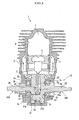
- An engine 1 shown in Fig. 1 is a two-stroke engine used for a portable working machine such as a chain saw, a bush cutter, and a blower.
- the engine 1 mainly includes a piston 5 installed in a cylinder 6 capable of a slidable movement in the cylinder 6, an intake port 7 communicating with the crank chamber 2, an exhaust port 8 communicating with a combustion chamber 4 at an upper part of the cylinder 6, a scavenging port 3 for communication between the crank chamber 2 and the combustion chamber 4, and a crankshaft assembly 10 including crankshafts 10A, 10B housed in the crank chamber 2 (see Fig. 2 ).
- the piston 5 is connected to the crankshafts 10A, 10B through a connecting rod 5a. Reciprocating motions of the piston 5 is converted into rotary motions of the crankshafts 10A, 10B.
- an exhaust port 8 communicates with the combustion chamber 4, so that the combustion gas is exhausted to the exhaust port 8.
- the pushed down piston 5 compresses the air-fuel mixture gas charged in the crank chamber 2.
- the scavenging port 3 becomes in a communication status with the combustion chamber 4.
- the air-fuel mixture gas in the crank chamber 2 flows into the cylinder 6 through the scavenging port 3.
- crankshafts 10A, 10B have, as shown in Fig. 2 , a crank journal 20 rotatably supported by a crankcase 2a, so that the crank journal 20 is rotatable on an axis of the crank journal 20.
- crankshaft 10A disposed on a left side in Fig. 2 and the crankshaft 10B disposed on a right side in Fig. 2 are integrally assembled and housed in the crank chamber 2.
- crankshafts 10A, 10B disposed on left and right sides in Fig. 2 have substantially symmetrical forms. There is a difference in that on the crankshaft 10B disposed on the right side in Fig. 2 a crank pin 31b is formed, and that on the crankshaft 10A on the left side in Fig. 2 a mounting hole 31a is formed.
- crankshafts 10A, 10B have the substantially symmetrical forms, only the crankshaft 10A disposed on the left side in Fig. 2 will be described in detail, and a description of the crankshaft 10B disposed on the right side in Fig. 2 will be omitted.
- the crankshaft 10A includes, as shown in Fig. 3 , a crank journal 20 which is a shaft having a circular cross section and a crank web 30 protruding from the crank journal 20 in a diametric direction of the crank journal 20.
- the crank journal 20 is formed integrally with the crank web 30 as a metal molded part.
- a filler member 40 is installed in the crank web 30 on the crankshaft 10A.
- crank journal 20 is inserted into a through hole 2b formed on a side of the crankshafts 10A, 10B, and a tip of the crank journal 20 protrudes from the crankshafts 10A, 10B to an outside of the crankshafts 10A, 10B.
- the crank journal 20 is inserted into a hole of a bearing 2c to be rotatably supported on an axis thereof by the crankshafts 10A, 10B.
- the crank journal 20 is an output shaft for transmitting a drive force generated by the engine 1 to an outside drive mechanism.
- the crank web 30 is, as shown in Fig. 2 , a plate member formed at a base part (en end of the crank chamber 2) of the crank journal 20.
- the crank web 30 includes, as shown in Fig. 4 , an arm 31 having a mounting hole 31a, a weight member 32 offset in an opposite direction of the mounting hole 31a across a rotating center of the crank journal 20.
- the arm 31 is a linearly formed part extending from the crank journal 20 in a diametric direction of the crank journal 20 (upward and downward directions in Fig. 4 ), and a part protruding upward from the crank journal 20 in Fig. 4 is formed longer than a part protruding downward from the crank journal 20 (see Fig. 1 ).
- the crankshaft 10A shown on the left side in Fig. 2 has the mounting through hole 31a in a tip of the arm 31 (a lower end shown in Fig. 2 ).
- the crankshaft 10B shown in the right side in Fig. 2 has the crank pin 31b at a tip of the arm 31 (lower end in Fig. 2 ).
- crank pin 31b of the crankshaft 10B on the right side in Fig. 2 is inserted into a through hole 5c formed in a lower end of the connecting rod 5a rotatably, and a tip of the crank pin 31b is inserted into the mounting hole 31a of the crankshaft 10A and fixed to the crankshaft 10A.
- the mounting hole 31a formed in the arm 31 or the crank pin 31b are parts connected to the connecting rod 5a as a connecting rod connection part.
- the weight member 32 is, as shown in Fig. 1 , formed at a base part (a lower end in Fig. 1 ) of the arm 31.
- the weight member 32 extends on both sides of the arm 31 in rotational direction of the arm 31 and has a fan shape having an arc shape at outer edge in a diametrical direction.
- crank web 30 is formed in a T-shape with the arm 31 linearly extending and the weight member 32 formed at the base part of the arm 31 to have the fan shape.
- the filler member 40 includes, as shown in Fig. 4 , a fitting member 41 with two bodies 43, 43 on both sides of a through hole 42a, and a connecting member 45 fixed to both the bodies 43 and 43.
- the fitting member 41 is fixed to an outer face 30a of the crank web 30 as shown in Fig. 3 by inserting the crank journal 20 into the through hole 42a.
- the connecting member 45 is configured to be fixed to both the body 43, 43 on a side of an inner face 30b of the crank web 30.
- the fitting member 41 includes a flat plate 42, two bodies 43, 43 disposed on both sides of the flat plate 42 in a width direction of the flat plate 42.
- the fitting member 41 is a plastic part into which the flat plate 42 and both the bodies 43, 43 are integrally formed.
- the plastic having a high moldability, reduces a weight of the fitting member 41 and a manufacturing cost.
- the fitting member 41 is formed with a plastic material having a relatively high heat resistance.
- the flat plate 42 is a planar part having the circular through hole 42a at a center in the width direction of the flat plate 42.
- the flat plate 42 is sandwiched between the crank web 30 and a bearing 2c in a state in which the crank journal 20 is inserted into the through hole 42a.
- Both the bodies 43, 43 are arranged on both sides of the arm 31 as shown in Fig. 3 .
- Both the bodies 43, 43 are formed, as shown in Fig. 4 , on both sides of a width direction of the flat plate 42 and protrude from the flat plate 42 on a side of the crank web 30.
- a thickness of both the bodies 43, 43 is set so that tip faces 43a, 43a of both the bodies 43, 43 are substantially flush with an inner face 30b of the crank web 30 in height.
- the bodies 43, 43 are formed with a plastic material having a small specific gravity, the bodies 43, 43 are lighter in weight than the weight member 32 of the crank web 30.
- a region of a side face of the body 43 facing the crank web 30 is formed along shapes of the arm 31 and the weight member 32.
- a region of a side face of the body 43 exposed to the inside of the crank chamber 2 is formed in an arc shape (surface) continuous to an arc edge face of the weight member 32.
- both the bodies 43, 43 are arranged on both sides of the arm 31 in a rotation direction of the arm 31, the crank web 30 and both the bodies 43, 43 have a circular plate shape.
- protruded locking members (column) 44 having a circular cross section are formed on tip faces 43a of the bodies 43.
- the locking members 44 are parts with which engaging parts 45a of the connecting member 45 are to be engaged (see Fig. 3 ).
- An outer circumferential edge of a tip face of the locking member 44 has an enlarged-diameter part 44a protruding in a diametrical direction of the locking member 44 as a claw.
- a line crossing the centers of both the locking members 44 crosses a rotation center of the crank journal 20 inserted into the through hole 42a.
- the connecting member 45 comprises a steel wire (a wire body) such as a piano wire as shown in Fig. 4 .
- a steel wire has a circular cross section with respect to an axial direction thereof.
- the connecting member 45 is formed to have an S-shape having the engaging parts 45a, 45a by bending both ends of the steel wire to have arc shapes curving in opposite directions.
- the engaging parts 45a is, as shown in Fig. 3 , a part to be engaged by fitting to an outer circumference of the locking member 44 of the body 43 and pushed down.
- the engaging part 45a is pushed down after riding over the enlarged-diameter part 44a, which provides a stopper for the engaging parts 45a with the enlarged-diameter part 44a.
- the connecting member 45 is fixed to both bodies 43, 43 by fitting the engaging part 45a to the outer circumference of the locking member 44 and pushing down without any tool.
- the connecting member 45 has appropriate flexibilities throughout all parts thereof to facilitate to be fitted to the outer circumference of the engaging parts 45a, 45a and pushed down.
- the connecting member 45 fixed to both the bodies 43, 43 is arranged as shown in Fig. 1 , such that the connecting member 45 strides the arm 31 of the crank web 30.
- a middle of the connecting member 45 slantwise strides the rotation center of the crank journal 20 necessarily because a line crossing centers of both the locking members 44 crosses a rotation center of the crank journal 20 (see Fig. 5 ), when both the ends of the connecting member 45 are fixed to the locking members 44, 44.
- sandwiching the crank web 30 between the fitting member 41 and the connecting member 45 provides fixation of the filler member 40 to the crank web 30 and disposes both the bodies 43 on both sides of the arm 31 in the rotation direction of the arm 31.
- both the bodies 43, 43 are made lighter than the weight member 32, which provides such a configuration that a variation in weight balance of the crank web 30 is avoided even in a status in which the filler member 40 is assembled in the crank web 30.
- An engine 1 having the crankshafts 10A and 10B to which the filler member 40 is fixed provides an advantageous effect as follows:
- the filler member 40 according to the first embodiment can be fixed to the crank web 30 by that the crank web 30 is sandwiched between the fitting member 41 and the connecting member 45.
- both the bodies 43, 43 are connected to the connecting member 45 which strides the arm 31. This prevents both the bodies 43, 43 from being deformed.
- the connecting member 45 at a middle part thereof is disposed to stride the rotation center of the crank journal 20 slantwise to the diametrical direction of the crank journal 20. This increases a resistant strength of the connecting member 45 to a centrifugal force.
- the connecting member 45 can be down-sized and has a simple shape, which reduces a manufacturing cost of the connecting member 45.
- the connecting member 45 can be simply mounted on both the bodies 43, 43 by fitting the engaging parts 45a, 45a of the connecting member 45 to the outer circumferences of the locking member 44 on the bodies 43, 43. Because the connecting member 45, having a flexibility, can be deformed throughout respective parts thereof, both the engaging parts 45a, 45a can be easily fitted and pushed down into the locking members 44, 44.
- the connecting member 45 is provided by bending both ends of a wire to form the engaging parts 45a, 45a, the connecting member 45 can be easily formed.
- the connecting member 45 is bent at both ends thereof to have an arc shape and has a circular cross section, which prevents both the bodies 43, 43 and the connecting member 45 itself from being damaged due to contact between edge of connecting member and the bodies when the connecting member 45 is fixed to both the bodies 43, 43, so that a durability of the filler member 40 is increased.
- Making the cross section with respect to an axis of the connecting member 45 circular can reduce stress concentration caused by an external force acting on the connecting member 45 from the locking member 44.
- the fitting member 41 is formed with a plastic material, and the connecting member 45 is formed with a steel wire.
- the material is not limited to this, but the fitting member 41 may be formed with a metal material, and the connecting member 45 is formed with a plastic material.
- Fig. 6 is a side view of a fitting member according to a second embodiment of the present invention, wherein a flat plate is extended.
- a shape of the fitting member 41 is not limited to the above-described shape, but may be extended downwardly as shown in Fig. 6 so that the flat plate 42 can overlap with the weight member 32 (see Fig. 4 ) entirely. This increases a stability of the filler member 40.
- a wall may be stood so as to contact an outer circumferential face of the weight member 32. Both bodies 43, 43 may be connected continuously outside the arm 31. Accordingly, the stability of the filler member 40 can be increased.
- a shape of the body 43 is not limited to the shape shown in Fig. 3 , but may be hollowed by forming channels and holes to reduce the weight.
- the crank web 30 and both the bodies 43, 43 may be formed not to have a disk shape, but it is sufficient to dispose the bodies 43, 43 on both sides of the arm 31 in the rotation direction of the arm 31.
- the connecting member 45 is formed with a steel wire having S-shaped, but the shape is not limited to this.
- Fig. 7A is a plan view of a connecting member having an 8-shape according to a third embodiment.
- a steel wire may be formed in an 8-shape, and ring parts 46a, 46a formed at both ends may be fitted into an outer circumference of the locking member 44 (see Fig. 5 ).
- Fig. 7B is a plan view of a connecting member having an oblong circular shape according to a fourth embodiment.
- a steel wire may be formed in an oblong shape, both the locking member 44, 44 (see Fig. 5 ) may be hooked on inner circumferential part 47a.
- Fig. 7C is a perspective view of a connecting member of a flat plate according to a fifth embodiment.
- a connecting member 48 is made as shown in Fig. 7C to have through holes 48a, 48a formed at both end in a longitudinal direction of a flat plate, and both the through holes 48a, 48a may be fitted to outer circumferences of the locking members 44.
- the connecting member may be divided in left-right direction into left and right parts which are engaged with the locking member 44, respectively. After that, the left and right parts may be connected.
- an oblong connecting member is divided in the left-right direction, two U-shape connecting members are slid in left and right direction to outer circumferences of the locking member 44, and the connecting member may be connected on the inner face 30b of the weight member 32.
- configuration of the two connecting members is not limited to this, but connection may be made by fitting a protrusion formed on one connecting member into a channel formed in the other connecting member.
- the divided connecting members have simple shapes, so that accuracy in processing can be increased.
- Fig. 7D is a perspective view of a connecting member having protrusions according to a sixth embodiment.
- a connecting member 49 shown in Fig. 7D can be formed to have protrusions 49a, 49a at both ends in a longitudinal direction of a flat plate, and the protrusions are inserted into through holes formed in the bodies.
- the connecting member 45 is formed so as to stride the rotation center of the crank journal 20.
- the position is not limited to this.
- a plurality of connecting members may be mounted on both the bodies 43, 43.
Landscapes
- Engineering & Computer Science (AREA)
- General Engineering & Computer Science (AREA)
- Ocean & Marine Engineering (AREA)
- Mechanical Engineering (AREA)
- Shafts, Cranks, Connecting Bars, And Related Bearings (AREA)
Claims (6)
- Ein Füllelement (40) für einen Einbau in eine Kurbelwelle (10A, 10B) umfassend eine Kurbelwange (30) umfassend:ein Armelement (31), das sich in einer diametralen Richtung von einem Kurbelzapfen (20) erstreckt, umfassend einen Pleuelstangeverbindungsteil (31 a, 31 b) für eine Verbindung mit einer Pleuelstange (5a);ein Gewichtelement (32), das gegenüber dem Pleuelstangeverbindungsteil (31 a, 31 b) über einem rotierenden Zentrum des Kurbelzapfens angeordnet ist, das sich auf beiden Seiten des Armelements (31) in einer radialen Richtung des Kurbelzapfens erstreckt, das Füllelement (40) aufweisend:ein Montageelement (41) umfassend eine Durchgangsbohrung (42a) und zwei Körper (43), die an beiden Seiten der Durchgangsbohrung (42a) ausgebildet sind; undein Verbindungselement (45), das auf den Körpern (43) montiert ist, wobei der Kurbelzapfen (20) in die Durchgangsbohrung (42a) hinein eingefügt werden muss und das Montageelement (41) an einer Seitenfläche (30a) der Kurbelwange (30) befestigt ist, um die Körper (43) auf beiden Seiten des Armelements (31) in einer Rotationsrichtung des Armelements (31) anzuordnen; wobeidas Verbindungselement (45) auf den Körpern (43) montiert ist, um das Armelement (31) auf einer anderen Seitenfläche (30b) der Kurbelwange (30) zu überschreiten und wobeidie Kurbelwange (30) zwischen dem Montageelement (41) und dem Verbindungselement (45) zusammengepresst wird.
- Das Füllelement wie in Anspruch 1 beansprucht, wobei das Verbindungselement (45) angeordnet ist, um ein rotierendes Zentrum des Kurbelzapfens (20) zu überschreiten.
- Das Füllelement wie in Anspruch 1 oder 2 beansprucht, wobei
die Körper (43) Verriegelungselemente (44) umfassen, die aus den Körpern herausragen und wobei
das Verbindungselement (45) Kupplungsteile (45a) umfasst, die mit äußeren Umfängen der Verriegelungselemente (44) gekuppelt sind. - Das Füllelement wie in Anspruch 1 beansprucht, wobei
die Körper (43) Verriegelungselemente (44) umfassen, die von dort herausragen, wobei
das Verbindungsteil (45) Kupplungsteile (45a) umfasst, die mit äußeren Umfängen der Verriegelungselemente (44) gekuppelt sind, und wobei
eine Linie, die Zentrumspositionen der Kupplungsteile (44) verbindet, ein Rotationszentrum des Kurbelzapfens (20) durchläuft. - Das Füllelement wie in Anspruch 3 oder 4 beansprucht, wobei das Verbindungselement einen Draht aufweist und die Kupplungsteile (45a) durch Biegen beider Enden des Drahts gebildet sind.
- Das Füllelement wie in einem der Ansprüche 3 bis 5 beansprucht, wobei das oder jedes Verriegelungselement (45) ein im Durchmesser erweitertes Element an einer Spitze des Verriegelungselements aufweist, das einen Durchmesser hat, der größer als ein Durchmesser einer Basis des Verriegelungselements ist, und das Kupplungsteil (45a) des Verbindungselements (45) ist mit einem äußeren Umfang der Basis des Verriegelungselements (45) gekuppelt.
Applications Claiming Priority (1)
| Application Number | Priority Date | Filing Date | Title |
|---|---|---|---|
| JP2010269345A JP5649937B2 (ja) | 2010-12-02 | 2010-12-02 | クランクシャフトの充填部材 |
Publications (3)
| Publication Number | Publication Date |
|---|---|
| EP2461052A2 EP2461052A2 (de) | 2012-06-06 |
| EP2461052A3 EP2461052A3 (de) | 2014-05-14 |
| EP2461052B1 true EP2461052B1 (de) | 2015-03-04 |
Family
ID=45092290
Family Applications (1)
| Application Number | Title | Priority Date | Filing Date |
|---|---|---|---|
| EP20110191803 Active EP2461052B1 (de) | 2010-12-02 | 2011-12-02 | Füllelement für eine Kurbelwelle |
Country Status (4)
| Country | Link |
|---|---|
| US (1) | US8468910B2 (de) |
| EP (1) | EP2461052B1 (de) |
| JP (1) | JP5649937B2 (de) |
| CN (1) | CN102537204B (de) |
Families Citing this family (6)
| Publication number | Priority date | Publication date | Assignee | Title |
|---|---|---|---|---|
| JP6065416B2 (ja) * | 2012-06-06 | 2017-01-25 | 株式会社やまびこ | 回転体 |
| DE112021001236T5 (de) * | 2020-03-30 | 2022-12-22 | Husqvarna Ab | Kurbelwelle, Antriebseinheit, Zweitaktkolbenmotor und handgehaltenes angetriebenes Werkzeug |
| JP7517858B2 (ja) | 2020-04-07 | 2024-07-17 | 株式会社やまびこ | 回転体 |
| CN112727905B (zh) * | 2020-12-25 | 2022-05-10 | 重庆隆鑫通航发动机制造有限公司 | 曲轴总成及发动机 |
| US11255374B1 (en) * | 2021-03-04 | 2022-02-22 | VenTec LLC | Engine crank |
| US11668229B1 (en) | 2022-06-08 | 2023-06-06 | Kenneth John Lodge | Engine crank with air channels |
Family Cites Families (23)
| Publication number | Priority date | Publication date | Assignee | Title |
|---|---|---|---|---|
| JPS57120719A (en) * | 1981-01-16 | 1982-07-27 | Mitsubishi Heavy Ind Ltd | Crankshaft |
| JPS5854214A (ja) * | 1981-09-25 | 1983-03-31 | Honda Motor Co Ltd | 二サイクル内燃機関のクランクシヤフト |
| JPH03272313A (ja) | 1990-03-20 | 1991-12-04 | Honda Motor Co Ltd | 2サイクルエンジンのクランクシャフト |
| JPH04203516A (ja) | 1990-11-29 | 1992-07-24 | Suzuki Motor Corp | 2サイクルエンジンのクランクシャフト |
| JP3223515B2 (ja) | 1991-03-20 | 2001-10-29 | スズキ株式会社 | 2サイクルエンジンのクランクシャフト |
| SE506343C2 (sv) * | 1996-04-09 | 1997-12-08 | Electrolux Ab | Anordning i en tvåtaktsförbränningsmotor |
| US6044818A (en) * | 1998-08-26 | 2000-04-04 | Almarv Llc | Vibration dampener for internal combustion engines |
| US6412366B1 (en) * | 2000-07-05 | 2002-07-02 | Donald G. Leith | Engine counterweight |
| CN1196869C (zh) * | 2000-10-20 | 2005-04-13 | 唐纳德·G·利思 | 曲轴和制造曲轴的方法 |
| US6418902B1 (en) * | 2001-02-08 | 2002-07-16 | Wci Outdoor Products, Inc. | Composite full circle crankshaft counterweight |
| US6526935B2 (en) * | 2001-06-08 | 2003-03-04 | Ralph Shaw | Cardioid cycle internal combustion engine |
| JP4911214B2 (ja) * | 2001-07-11 | 2012-04-04 | 株式会社Gsユアサ | 電池 |
| US6874458B2 (en) * | 2001-12-28 | 2005-04-05 | Kohler Co. | Balance system for single cylinder engine |
| JP4159293B2 (ja) | 2002-02-06 | 2008-10-01 | 本田技研工業株式会社 | クランクシャフト |
| US6688272B2 (en) * | 2002-05-29 | 2004-02-10 | Ford Global Technologies, Llc | Crankshaft assembly for enabling engine cylinder deactivation |
| US20040035244A1 (en) * | 2002-08-20 | 2004-02-26 | Leith Donald G. | Crankshaft assembly and method for manufacturing same |
| JP2004300933A (ja) * | 2003-03-28 | 2004-10-28 | Sanyo Electric Co Ltd | 往復ピストン圧縮機 |
| JP2005076738A (ja) | 2003-08-29 | 2005-03-24 | Suzuki Motor Corp | 内燃機関のクランクシャフト |
| JP4392224B2 (ja) * | 2003-11-04 | 2009-12-24 | 株式会社Ihiシバウラ | 2サイクルエンジン |
| JP2005172032A (ja) | 2003-12-08 | 2005-06-30 | Nissan Motor Co Ltd | 内燃機関のクランクシャフト構造 |
| JP2007024155A (ja) | 2005-07-14 | 2007-02-01 | Toyota Motor Corp | クランクシャフト |
| DE102006030493B4 (de) * | 2006-07-01 | 2019-05-29 | Secop Gmbh | Kompressor-Kurbelwelle, insbesondere Kältemittelkompressor-Kurbelwelle, und Verfahren zu ihrer Herstellung |
| JP3133309U (ja) * | 2007-04-26 | 2007-07-05 | 株式会社 近藤工作所 | 自動車エンジン用のクランクシャフト |
-
2010
- 2010-12-02 JP JP2010269345A patent/JP5649937B2/ja active Active
-
2011
- 2011-12-01 US US13/308,647 patent/US8468910B2/en active Active
- 2011-12-02 CN CN201110400179.6A patent/CN102537204B/zh active Active
- 2011-12-02 EP EP20110191803 patent/EP2461052B1/de active Active
Also Published As
| Publication number | Publication date |
|---|---|
| CN102537204A (zh) | 2012-07-04 |
| CN102537204B (zh) | 2015-04-01 |
| JP2012117630A (ja) | 2012-06-21 |
| EP2461052A3 (de) | 2014-05-14 |
| EP2461052A2 (de) | 2012-06-06 |
| JP5649937B2 (ja) | 2015-01-07 |
| US8468910B2 (en) | 2013-06-25 |
| US20120137827A1 (en) | 2012-06-07 |
Similar Documents
| Publication | Publication Date | Title |
|---|---|---|
| EP2461052B1 (de) | Füllelement für eine Kurbelwelle | |
| CN101900098B (zh) | 往复运动压缩机 | |
| CN109931181B (zh) | 曲轴盖组装体和内燃机 | |
| EP1533495B1 (de) | Brennkraftmaschine | |
| JP2002188455A (ja) | 複リンク型レシプロ式内燃機関のクランク機構 | |
| CN104454223B (zh) | 发动机的活塞构造 | |
| CN2704691Y (zh) | 具有可变压缩比的发动机 | |
| JP2000064905A (ja) | 内然機関のピストン | |
| US20090120280A1 (en) | Fuel injection pump and method for assembling the same | |
| JP2004124775A (ja) | 内燃機関の可変圧縮比機構 | |
| JP4392224B2 (ja) | 2サイクルエンジン | |
| JP4251962B2 (ja) | 2サイクルエンジン | |
| JP3204412U (ja) | カム駆動式レシプロ型エンジン | |
| CN115398107B (zh) | 旋转体 | |
| US20070017763A1 (en) | Energy conversion device including a piston without O-rings | |
| JP2008038885A (ja) | 圧縮室を持つスコッチヨーク式ガソリンエンジン | |
| KR20030064009A (ko) | 실린더 로드와 크랭크 구조 | |
| JP2003097288A (ja) | 内燃機関の可変圧縮比機構 | |
| KR100657692B1 (ko) | 피스톤 부쉬 | |
| KR20030054916A (ko) | 차량 엔진용 피스톤 | |
| JPH04331874A (ja) | 内燃機関のピストン・コンロッド組立体 | |
| JPH0868382A (ja) | オイルフリー往復圧縮機 | |
| KR20010056920A (ko) | 내연기관용 피스톤과 커넥팅 로드의 결합 구조 | |
| JPH11218054A (ja) | ピストン | |
| KR20050038963A (ko) | 피스톤 압축링의 장착 구조 |
Legal Events
| Date | Code | Title | Description |
|---|---|---|---|
| PUAI | Public reference made under article 153(3) epc to a published international application that has entered the european phase |
Free format text: ORIGINAL CODE: 0009012 |
|
| AK | Designated contracting states |
Kind code of ref document: A2 Designated state(s): AL AT BE BG CH CY CZ DE DK EE ES FI FR GB GR HR HU IE IS IT LI LT LU LV MC MK MT NL NO PL PT RO RS SE SI SK SM TR |
|
| AX | Request for extension of the european patent |
Extension state: BA ME |
|
| PUAL | Search report despatched |
Free format text: ORIGINAL CODE: 0009013 |
|
| AK | Designated contracting states |
Kind code of ref document: A3 Designated state(s): AL AT BE BG CH CY CZ DE DK EE ES FI FR GB GR HR HU IE IS IT LI LT LU LV MC MK MT NL NO PL PT RO RS SE SI SK SM TR |
|
| AX | Request for extension of the european patent |
Extension state: BA ME |
|
| RIC1 | Information provided on ipc code assigned before grant |
Ipc: F16C 3/20 20060101ALI20140407BHEP Ipc: F16C 3/12 20060101AFI20140407BHEP |
|
| 17P | Request for examination filed |
Effective date: 20140805 |
|
| RBV | Designated contracting states (corrected) |
Designated state(s): AL AT BE BG CH CY CZ DE DK EE ES FI FR GB GR HR HU IE IS IT LI LT LU LV MC MK MT NL NO PL PT RO RS SE SI SK SM TR |
|
| GRAP | Despatch of communication of intention to grant a patent |
Free format text: ORIGINAL CODE: EPIDOSNIGR1 |
|
| INTG | Intention to grant announced |
Effective date: 20141010 |
|
| GRAS | Grant fee paid |
Free format text: ORIGINAL CODE: EPIDOSNIGR3 |
|
| GRAA | (expected) grant |
Free format text: ORIGINAL CODE: 0009210 |
|
| AK | Designated contracting states |
Kind code of ref document: B1 Designated state(s): AL AT BE BG CH CY CZ DE DK EE ES FI FR GB GR HR HU IE IS IT LI LT LU LV MC MK MT NL NO PL PT RO RS SE SI SK SM TR |
|
| REG | Reference to a national code |
Ref country code: GB Ref legal event code: FG4D |
|
| REG | Reference to a national code |
Ref country code: CH Ref legal event code: EP |
|
| REG | Reference to a national code |
Ref country code: IE Ref legal event code: FG4D |
|
| REG | Reference to a national code |
Ref country code: AT Ref legal event code: REF Ref document number: 714156 Country of ref document: AT Kind code of ref document: T Effective date: 20150415 |
|
| REG | Reference to a national code |
Ref country code: DE Ref legal event code: R096 Ref document number: 602011014286 Country of ref document: DE Effective date: 20150416 |
|
| REG | Reference to a national code |
Ref country code: AT Ref legal event code: MK05 Ref document number: 714156 Country of ref document: AT Kind code of ref document: T Effective date: 20150304 Ref country code: NL Ref legal event code: VDEP Effective date: 20150304 |
|
| PG25 | Lapsed in a contracting state [announced via postgrant information from national office to epo] |
Ref country code: FI Free format text: LAPSE BECAUSE OF FAILURE TO SUBMIT A TRANSLATION OF THE DESCRIPTION OR TO PAY THE FEE WITHIN THE PRESCRIBED TIME-LIMIT Effective date: 20150304 Ref country code: HR Free format text: LAPSE BECAUSE OF FAILURE TO SUBMIT A TRANSLATION OF THE DESCRIPTION OR TO PAY THE FEE WITHIN THE PRESCRIBED TIME-LIMIT Effective date: 20150304 Ref country code: NO Free format text: LAPSE BECAUSE OF FAILURE TO SUBMIT A TRANSLATION OF THE DESCRIPTION OR TO PAY THE FEE WITHIN THE PRESCRIBED TIME-LIMIT Effective date: 20150604 Ref country code: SE Free format text: LAPSE BECAUSE OF FAILURE TO SUBMIT A TRANSLATION OF THE DESCRIPTION OR TO PAY THE FEE WITHIN THE PRESCRIBED TIME-LIMIT Effective date: 20150304 Ref country code: ES Free format text: LAPSE BECAUSE OF FAILURE TO SUBMIT A TRANSLATION OF THE DESCRIPTION OR TO PAY THE FEE WITHIN THE PRESCRIBED TIME-LIMIT Effective date: 20150304 Ref country code: LT Free format text: LAPSE BECAUSE OF FAILURE TO SUBMIT A TRANSLATION OF THE DESCRIPTION OR TO PAY THE FEE WITHIN THE PRESCRIBED TIME-LIMIT Effective date: 20150304 |
|
| REG | Reference to a national code |
Ref country code: LT Ref legal event code: MG4D |
|
| PG25 | Lapsed in a contracting state [announced via postgrant information from national office to epo] |
Ref country code: LV Free format text: LAPSE BECAUSE OF FAILURE TO SUBMIT A TRANSLATION OF THE DESCRIPTION OR TO PAY THE FEE WITHIN THE PRESCRIBED TIME-LIMIT Effective date: 20150304 Ref country code: RS Free format text: LAPSE BECAUSE OF FAILURE TO SUBMIT A TRANSLATION OF THE DESCRIPTION OR TO PAY THE FEE WITHIN THE PRESCRIBED TIME-LIMIT Effective date: 20150304 Ref country code: GR Free format text: LAPSE BECAUSE OF FAILURE TO SUBMIT A TRANSLATION OF THE DESCRIPTION OR TO PAY THE FEE WITHIN THE PRESCRIBED TIME-LIMIT Effective date: 20150605 Ref country code: AT Free format text: LAPSE BECAUSE OF FAILURE TO SUBMIT A TRANSLATION OF THE DESCRIPTION OR TO PAY THE FEE WITHIN THE PRESCRIBED TIME-LIMIT Effective date: 20150304 |
|
| PG25 | Lapsed in a contracting state [announced via postgrant information from national office to epo] |
Ref country code: NL Free format text: LAPSE BECAUSE OF FAILURE TO SUBMIT A TRANSLATION OF THE DESCRIPTION OR TO PAY THE FEE WITHIN THE PRESCRIBED TIME-LIMIT Effective date: 20150304 |
|
| PG25 | Lapsed in a contracting state [announced via postgrant information from national office to epo] |
Ref country code: CZ Free format text: LAPSE BECAUSE OF FAILURE TO SUBMIT A TRANSLATION OF THE DESCRIPTION OR TO PAY THE FEE WITHIN THE PRESCRIBED TIME-LIMIT Effective date: 20150304 Ref country code: SK Free format text: LAPSE BECAUSE OF FAILURE TO SUBMIT A TRANSLATION OF THE DESCRIPTION OR TO PAY THE FEE WITHIN THE PRESCRIBED TIME-LIMIT Effective date: 20150304 Ref country code: PT Free format text: LAPSE BECAUSE OF FAILURE TO SUBMIT A TRANSLATION OF THE DESCRIPTION OR TO PAY THE FEE WITHIN THE PRESCRIBED TIME-LIMIT Effective date: 20150706 Ref country code: RO Free format text: LAPSE BECAUSE OF FAILURE TO SUBMIT A TRANSLATION OF THE DESCRIPTION OR TO PAY THE FEE WITHIN THE PRESCRIBED TIME-LIMIT Effective date: 20150304 Ref country code: EE Free format text: LAPSE BECAUSE OF FAILURE TO SUBMIT A TRANSLATION OF THE DESCRIPTION OR TO PAY THE FEE WITHIN THE PRESCRIBED TIME-LIMIT Effective date: 20150304 |
|
| PG25 | Lapsed in a contracting state [announced via postgrant information from national office to epo] |
Ref country code: IS Free format text: LAPSE BECAUSE OF FAILURE TO SUBMIT A TRANSLATION OF THE DESCRIPTION OR TO PAY THE FEE WITHIN THE PRESCRIBED TIME-LIMIT Effective date: 20150704 Ref country code: PL Free format text: LAPSE BECAUSE OF FAILURE TO SUBMIT A TRANSLATION OF THE DESCRIPTION OR TO PAY THE FEE WITHIN THE PRESCRIBED TIME-LIMIT Effective date: 20150304 |
|
| REG | Reference to a national code |
Ref country code: DE Ref legal event code: R097 Ref document number: 602011014286 Country of ref document: DE |
|
| REG | Reference to a national code |
Ref country code: FR Ref legal event code: PLFP Year of fee payment: 5 |
|
| PLBE | No opposition filed within time limit |
Free format text: ORIGINAL CODE: 0009261 |
|
| STAA | Information on the status of an ep patent application or granted ep patent |
Free format text: STATUS: NO OPPOSITION FILED WITHIN TIME LIMIT |
|
| PG25 | Lapsed in a contracting state [announced via postgrant information from national office to epo] |
Ref country code: DK Free format text: LAPSE BECAUSE OF FAILURE TO SUBMIT A TRANSLATION OF THE DESCRIPTION OR TO PAY THE FEE WITHIN THE PRESCRIBED TIME-LIMIT Effective date: 20150304 |
|
| 26N | No opposition filed |
Effective date: 20151207 |
|
| PG25 | Lapsed in a contracting state [announced via postgrant information from national office to epo] |
Ref country code: SI Free format text: LAPSE BECAUSE OF FAILURE TO SUBMIT A TRANSLATION OF THE DESCRIPTION OR TO PAY THE FEE WITHIN THE PRESCRIBED TIME-LIMIT Effective date: 20150304 |
|
| PG25 | Lapsed in a contracting state [announced via postgrant information from national office to epo] |
Ref country code: BE Free format text: LAPSE BECAUSE OF NON-PAYMENT OF DUE FEES Effective date: 20151231 |
|
| PG25 | Lapsed in a contracting state [announced via postgrant information from national office to epo] |
Ref country code: LU Free format text: LAPSE BECAUSE OF FAILURE TO SUBMIT A TRANSLATION OF THE DESCRIPTION OR TO PAY THE FEE WITHIN THE PRESCRIBED TIME-LIMIT Effective date: 20151202 Ref country code: MC Free format text: LAPSE BECAUSE OF FAILURE TO SUBMIT A TRANSLATION OF THE DESCRIPTION OR TO PAY THE FEE WITHIN THE PRESCRIBED TIME-LIMIT Effective date: 20150304 |
|
| REG | Reference to a national code |
Ref country code: CH Ref legal event code: PL |
|
| GBPC | Gb: european patent ceased through non-payment of renewal fee |
Effective date: 20151202 |
|
| PG25 | Lapsed in a contracting state [announced via postgrant information from national office to epo] |
Ref country code: BE Free format text: LAPSE BECAUSE OF FAILURE TO SUBMIT A TRANSLATION OF THE DESCRIPTION OR TO PAY THE FEE WITHIN THE PRESCRIBED TIME-LIMIT Effective date: 20150304 |
|
| REG | Reference to a national code |
Ref country code: IE Ref legal event code: MM4A |
|
| PG25 | Lapsed in a contracting state [announced via postgrant information from national office to epo] |
Ref country code: IE Free format text: LAPSE BECAUSE OF NON-PAYMENT OF DUE FEES Effective date: 20151202 Ref country code: GB Free format text: LAPSE BECAUSE OF NON-PAYMENT OF DUE FEES Effective date: 20151202 Ref country code: LI Free format text: LAPSE BECAUSE OF NON-PAYMENT OF DUE FEES Effective date: 20151231 Ref country code: CH Free format text: LAPSE BECAUSE OF NON-PAYMENT OF DUE FEES Effective date: 20151231 |
|
| REG | Reference to a national code |
Ref country code: FR Ref legal event code: PLFP Year of fee payment: 6 |
|
| PG25 | Lapsed in a contracting state [announced via postgrant information from national office to epo] |
Ref country code: HU Free format text: LAPSE BECAUSE OF FAILURE TO SUBMIT A TRANSLATION OF THE DESCRIPTION OR TO PAY THE FEE WITHIN THE PRESCRIBED TIME-LIMIT; INVALID AB INITIO Effective date: 20111202 Ref country code: BG Free format text: LAPSE BECAUSE OF FAILURE TO SUBMIT A TRANSLATION OF THE DESCRIPTION OR TO PAY THE FEE WITHIN THE PRESCRIBED TIME-LIMIT Effective date: 20150304 Ref country code: SM Free format text: LAPSE BECAUSE OF FAILURE TO SUBMIT A TRANSLATION OF THE DESCRIPTION OR TO PAY THE FEE WITHIN THE PRESCRIBED TIME-LIMIT Effective date: 20150304 |
|
| PG25 | Lapsed in a contracting state [announced via postgrant information from national office to epo] |
Ref country code: CY Free format text: LAPSE BECAUSE OF FAILURE TO SUBMIT A TRANSLATION OF THE DESCRIPTION OR TO PAY THE FEE WITHIN THE PRESCRIBED TIME-LIMIT Effective date: 20150304 |
|
| PG25 | Lapsed in a contracting state [announced via postgrant information from national office to epo] |
Ref country code: MT Free format text: LAPSE BECAUSE OF FAILURE TO SUBMIT A TRANSLATION OF THE DESCRIPTION OR TO PAY THE FEE WITHIN THE PRESCRIBED TIME-LIMIT Effective date: 20150304 Ref country code: TR Free format text: LAPSE BECAUSE OF FAILURE TO SUBMIT A TRANSLATION OF THE DESCRIPTION OR TO PAY THE FEE WITHIN THE PRESCRIBED TIME-LIMIT Effective date: 20150304 |
|
| REG | Reference to a national code |
Ref country code: FR Ref legal event code: PLFP Year of fee payment: 7 |
|
| PG25 | Lapsed in a contracting state [announced via postgrant information from national office to epo] |
Ref country code: MK Free format text: LAPSE BECAUSE OF FAILURE TO SUBMIT A TRANSLATION OF THE DESCRIPTION OR TO PAY THE FEE WITHIN THE PRESCRIBED TIME-LIMIT Effective date: 20150304 |
|
| PG25 | Lapsed in a contracting state [announced via postgrant information from national office to epo] |
Ref country code: AL Free format text: LAPSE BECAUSE OF FAILURE TO SUBMIT A TRANSLATION OF THE DESCRIPTION OR TO PAY THE FEE WITHIN THE PRESCRIBED TIME-LIMIT Effective date: 20150304 |
|
| REG | Reference to a national code |
Ref country code: DE Ref legal event code: R082 Ref document number: 602011014286 Country of ref document: DE |
|
| PGFP | Annual fee paid to national office [announced via postgrant information from national office to epo] |
Ref country code: DE Payment date: 20251211 Year of fee payment: 15 |
|
| PGFP | Annual fee paid to national office [announced via postgrant information from national office to epo] |
Ref country code: IT Payment date: 20251223 Year of fee payment: 15 |
|
| PGFP | Annual fee paid to national office [announced via postgrant information from national office to epo] |
Ref country code: FR Payment date: 20251222 Year of fee payment: 15 |