EP2460160B1 - Systeme und verfahren zur plasmakompression mit geschoss-recycling - Google Patents
Systeme und verfahren zur plasmakompression mit geschoss-recycling Download PDFInfo
- Publication number
- EP2460160B1 EP2460160B1 EP10740096.2A EP10740096A EP2460160B1 EP 2460160 B1 EP2460160 B1 EP 2460160B1 EP 10740096 A EP10740096 A EP 10740096A EP 2460160 B1 EP2460160 B1 EP 2460160B1
- Authority
- EP
- European Patent Office
- Prior art keywords
- plasma
- projectile
- liquid metal
- accelerator
- compression
- Prior art date
- Legal status (The legal status is an assumption and is not a legal conclusion. Google has not performed a legal analysis and makes no representation as to the accuracy of the status listed.)
- Active
Links
Images




Classifications
-
- G—PHYSICS
- G21—NUCLEAR PHYSICS; NUCLEAR ENGINEERING
- G21B—FUSION REACTORS
- G21B3/00—Low temperature nuclear fusion reactors, e.g. alleged cold fusion reactors
-
- H—ELECTRICITY
- H05—ELECTRIC TECHNIQUES NOT OTHERWISE PROVIDED FOR
- H05H—PLASMA TECHNIQUE; PRODUCTION OF ACCELERATED ELECTRICALLY-CHARGED PARTICLES OR OF NEUTRONS; PRODUCTION OR ACCELERATION OF NEUTRAL MOLECULAR OR ATOMIC BEAMS
- H05H1/00—Generating plasma; Handling plasma
- H05H1/02—Arrangements for confining plasma by electric or magnetic fields; Arrangements for heating plasma
-
- G—PHYSICS
- G21—NUCLEAR PHYSICS; NUCLEAR ENGINEERING
- G21B—FUSION REACTORS
- G21B3/00—Low temperature nuclear fusion reactors, e.g. alleged cold fusion reactors
- G21B3/006—Fusion by impact, e.g. cluster/beam interaction, ion beam collisions, impact on a target
-
- G—PHYSICS
- G21—NUCLEAR PHYSICS; NUCLEAR ENGINEERING
- G21B—FUSION REACTORS
- G21B3/00—Low temperature nuclear fusion reactors, e.g. alleged cold fusion reactors
- G21B3/008—Fusion by pressure waves
-
- H—ELECTRICITY
- H05—ELECTRIC TECHNIQUES NOT OTHERWISE PROVIDED FOR
- H05H—PLASMA TECHNIQUE; PRODUCTION OF ACCELERATED ELECTRICALLY-CHARGED PARTICLES OR OF NEUTRONS; PRODUCTION OR ACCELERATION OF NEUTRAL MOLECULAR OR ATOMIC BEAMS
- H05H1/00—Generating plasma; Handling plasma
- H05H1/54—Plasma accelerators
Definitions
- the present disclosure relates to embodiments of systems, methods and apparatus for plasma compression.
- Some systems for compressing plasma to high temperatures and densities typically are large, expensive, and are limited in repetition rate and operational lifetime.
- the addition of a magnetic field within the plasma is a promising method for improving the effectiveness of any given heating scheme due to decreased particle and energy loss rates from the plasma volume.
- Methods of compressing a plasma include the following six schemes.
- the compression of a conductive medium can be performed using an external pressurized gas. See, for example, the LINUS system described in R. L. Miller and R. A. Krakowski, "Assessment of the slowly-imploding liner (LINUS) fusion reactor concept", Rept. No. LA-UR-80-3071, Los Alamos Scientific Laboratory, Los Alamos, NM 1980 .
- the invention provides a system for compressing plasma as defined in claim 1.
- Preferred features of the system are the subject of dependent claims 2 to 10.
- the system includes a plasma injector that comprises a plasma formation system configured to generate a magnetized plasma and a plasma accelerator having a first portion, a second portion, and a longitudinal axis between the first portion and the second portion.
- the plasma accelerator is configured to receive the magnetized plasma at the first portion and to accelerate the magnetized plasma along the longitudinal axis toward the second portion.
- the system for compressing plasma also includes a liquid metal circulation system configured to provide liquid metal that forms at least a portion of a chamber configured to receive the magnetized plasma from the second portion of the plasma accelerator.
- the magnetized plasma can have a first pressure when received in the chamber.
- the system also includes a projectile accelerator configured to accelerate a projectile along at least a portion of the longitudinal axis toward the chamber.
- the system also includes a timing system configured to coordinate acceleration of the magnetized plasma and acceleration of the projectile. The system is configured such that the projectile compresses the magnetized plasma in the chamber such that the compressed magnetized plasma can have a second pressure that is greater than the first pressure.
- the invention provides a method of compressing a plasma as defined in claim 11.
- Preferred features of the method are the subject of dependent claims 12 and 13.
- the method comprises generating a toroidal plasma, accelerating the toroidal plasma toward a cavity in a liquid metal, accelerating a projectile toward the cavity in the liquid metal, and compressing the toroidal plasma with the projectile while the toroidal plasma is in the cavity in the liquid metal.
- the method may also include flowing a liquid metal to form the cavity.
- the method may also include recycling a portion of the liquid metal to form at least one new projectile.
- FIG.1 is a schematic cross-sectional diagram showing an example embodiment of a plasma compression system with liquid metal wall confinement, where the system comprises a projectile acceleration device, a plasma injector, a liquid metal recirculating vessel and a projectile formation subsystem.
- FIG. 2 is a schematic cross-sectional diagram showing a portion of an example embodiment of a plasma injector located coaxially around the muzzle of a projectile accelerator.
- the plasma injector is rotationally symmetric around the projectile acceleration axis 40a.
- FIG. 3 includes simplified schematic cross-sectional diagrams (A-I) that illustrate an example, in a time sequence, of how a projectile and plasma may behave from impact with a liquid metal to point of maximum pressure, and then subsequent fracture of projectile and intermixing with the liquid metal used for recycling of projectile material.
- Values of density in kg/m 3 are illustrated as grayscale levels according to the values in the status bar on the right of the figure.
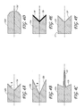
- FIGS. 4A-4F are schematic cross-sectional diagrams that illustrate various example embodiments of projectiles.
- FIG. 5 schematically shows an example of timing of gas vent valves in an example embodiment of a projectile accelerator.
- FIG. 6 is a flowchart that schematically illustrates an example embodiment of a method of compressing plasma in a liquid metal chamber using impact of a projectile on the magnetized plasma.
- Embodiments of the above-described compression schemes are generally pulsed in nature. Two possible factors to consider are the cost per pulse and the pulse repetition rate. Schemes that use high precision parts that are destroyed each pulse cycle (for example, schemes 2, 3, and some versions of scheme 6) may typically have a significantly higher cost per pulse than schemes that are either non-destructive (for example, scheme 1) or employ passive recycling of material (for example, schemes 4, 5, and some versions of scheme 6). Non-destructive pulse schemes tend to have the highest repetition rate (which may be limited by magnetic effects) that may be as high as in a kHz range in certain implementations. Passive recycling may be the next fastest with repetition rates (which may be limited by liner fluid flow velocities) that may be as high as several Hz in certain implementations. Schemes where the central assembly for the pulsed compression is destroyed every pulse tend to have the slowest intrinsic repetition rate, determined by time taken to clear destroyed elements and insert a new assembly. This is not likely to be more than once every few seconds at best in some implementations.
- schemes 4, 5, and 6 incorporate an absorber material, either by choice of material used for the compression liner fluid, and/or by the addition of material into large unused volumes surrounding the device.
- Systems with a recirculating absorber fluid can also provide a low cost method for extracting heat produced during compression. Recirculation of an absorber fluid can also allow radiation products from the compressed plasma to be used to transmute isotopes included in the absorber fluid. This approach can be used for processing waste material, or for providing a cost effective method of producing rare isotopes.
- Impact driven compression schemes have typically involved methods to accelerate small but macroscopic projectiles to the ultra-high velocities needed to compress and heat the solid projectiles into an extremely dense, hot plasma state, typically with no magnetic field, or a magnetic field with only marginal confinement properties. This typically requires the use of an extremely long electromagnetic accelerator (for example, up to several kilometer long) to develop the requisite velocity, resulting in prohibitive construction costs.
- Some embodiments of the present approach involve the use of the impact of a projectile to drive plasma compression, and provide a system configuration that enables a significantly smaller scale system with higher repetition rates and/or longer system lifetime than previous approaches.
- certain embodiments of the present approach utilize a larger mass traveling at lower velocity, which acts to compress a well-magnetized plasma. This can allow for the use of a less complex and less costly projectile acceleration method for compressing the plasma.
- a light gas gun can be used to accelerate the projectile to a speed of up to several km/s over a span of, for example, approximately 100 meters.
- Embodiments of the present approach may incorporate an integrated passive recycling system for the projectile material. This can allow for an improved (e.g., relatively high) repetition rate and/or an increase in system lifetime. With suitable choice of materials, the projectile and liner fluid can act as an efficient absorber of plasma radiation products, resulting in a system that has an economic feasibility and practical utility.
- plasma can be compressed by impact of a projectile on a magnetized plasma toroid in a liquid metal cavity.
- the projectile can melt in the liquid metal cavity, and liquid metal can be recycled to form new projectiles.
- the plasma can be heated during compression.
- FIG. 1 a schematic cross-sectional diagram of an embodiment of a new and improved example plasma compression system 10 is shown in FIG. 1 .
- the example system 10 includes a magnetized plasma formation/injection device 34, an accelerator 40 (for example, a light gas pneumatic gun or an electromagnetic accelerator), which fires projectiles 12 along an acceleration axis 40a toward compression chamber 26 defined in part by a converging flow of liquid metal 46.
- Liquid metal 46 is contained within liquid metal recirculating vessel 18, and a conical nozzle 24 directs the flow of liquid metal 46 into a magnetic flux conserving liner having a surface 27 with a desired shape at compression chamber 26.
- the compression chamber 26 may be substantially symmetric around an axis.
- the axis of the compression chamber 26 may be substantially collinear with the acceleration axis 40a (see, e.g., FIGS. 1 and 2 ).
- the system 10 may include a timing system (not shown) configured to coordinate the relative timing of events such as, e.g., formation of the plasma, acceleration of the plasma, firing or acceleration of the projectile, etc.
- a timing system (not shown) configured to coordinate the relative timing of events such as, e.g., formation of the plasma, acceleration of the plasma, firing or acceleration of the projectile, etc.
- the projectile velocity may be significantly less than the plasma injection velocity
- plasma formation and injection can be delayed and can be triggered by the timing system when the projectile 12 reaches a prescribed position (e.g., near the muzzle) of the accelerator 40.
- FIG. 1 schematically illustrates three example projectiles 12a, 12b, and 12c moving toward the compression chamber 26.
- a fourth projectile 12d is in the liquid metal 46 near the point of maximum compression of the plasma.
- the four projectiles 12a-12d are intended to illustrate features of the system 10 and are not intended to be limiting. For example, in other embodiments, different numbers of projectiles (e.g., 1, 2, 4, or more) may be accelerated by the accelerator 40 at any time.
- FIG. 1 also schematically illustrates a plasma torus in three different positions in the system 10.
- the magnetized plasma torus can be formed near a formation region 36a of the formation/injection device 34. The magnetized plasma shown at the position 36b has been accelerated and compressed between coaxial electrodes 48 and 50.
- the magnetized plasma expands off the end of the coaxial electrodes 48 and 50 into the larger volume of the compression chamber 26 defined by the front surface of projectile 12c (see FIG. 1 ) and the surface 27 of the liquid metal.
- the magnetized plasma can persist at the position 36c in the compression chamber 26 with a magnetic decay time that is several times longer than the compression time.
- the motion of the projectile 12c can compress the plasma near the position 36c, with the internal magnetic confinement of the plasma reducing or preventing significant particle loss back up into the plasma injector during the early phase of compression.
- the size of the projectile 12c transverse to the acceleration axis 40a is smaller than the size of the opening to the compression chamber 26 so that an annular opening exists around the outside of the projectile when the projectile is near the position 36c.
- a later phase of compression begins after the projectile 12c closes off the opening to the chamber, and the compression chamber 26 is substantially or fully enclosed by the surface 27 of the liquid metal and the projectile 12c. See, e.g., FIG. 3 which schematically depicts a simulated time sequence of the compression geometry.
- impact of the projectile 12 on the plasma in the compression chamber can increase the pressure, density, and/or temperature of the plasma.
- the plasma may have a first pressure (or density or temperature) when in the compression chamber 26, and a second pressure (or density or temperature) after impact of the projectile 12, the second pressure (or density or temperature) greater than the first pressure (or density or temperature).
- the second pressure (or density or temperature) can be greater than the first pressure (or density or temperature), for example, by a factor of 1.5, 2, 4, 10, 25, 50, 100, or more.
- the plasma may be heated.
- Net heating of the liquid metal 46 can occur due to the absorption of radiation products from the compressed plasma as well as thermalization of the projectile kinetic energy.
- the liquid metal 46 can be heated by as much as several hundred degrees Celsius by the plasma compression event.
- heat generated by plasma compression can extracted by the heat exchanger and used in an electrical power generation system (e.g., a turbine driven by steam generated from the extracted heat).
- the temperature of the liquid metal can be maintained moderately above its melting point (e.g., T melt + approximately 10-50 °C).
- the heat exchanger 16 can be any suitable heat exchanger.
- the heat exchanger output may be used in other processes.
- a recirculation pipe 30 can deliver a supply of the liquid metal 46 to projectile molds 32 in a subsystem for making new batches of projectiles (e.g., projectile factory 37 shown in FIG. 1 ).
- a loading mechanism 38 can be used to automatically load new projectiles into the breach of the accelerator 40.
- an array of projectiles 12 can be situated within a cartridge structure that can be loaded by the loading mechanism 38 into the breach of the accelerator 40 and fired in relatively rapid sequence along the acceleration axis 40a.
- a brief time period possibly as brief as 1-2 seconds in some implementations, without the accelerator 40 firing can be provided to allow for loading of the next cartridge of projectiles.
- the loading mechanism 38 can have a direct load-shoot-load-shoot cycle in which case a cartridge structure need not be used, and a substantially steady rate of projectile fire can be maintained.
- projectile molds 32 can be automated to receive recycled liquid metal 46, and provide a cooling cycle suitable to allow casting of new projectiles using various manufacturing methods.
- the rate of liquid metal recirculation and new projectile production can be sufficient to supply projectiles at the desired launch rate.
- the total cooling time for the liquid metal to sufficiently solidify within the molds can be taken up by parallelism within the method of preparing batches of new projectiles.
- the cooling time may be made as short as practical and/or may be determined by the amount of rigidity needed for proper mechanical function of the loading mechanism and/or the ability of the projectile 12 to survive acceleration down the gun. With this highly automated firing cycle, a reasonably high repetition rate can be achieved for extended durations.
- certain embodiments of the system 10 have the advantages of being effectively a closed-loop in which the solid projectile 12 can be fired into a vessel 18 filled with substantially the same material in liquid form, and the liquid metal 46 can be recycled to form new projectiles 12.
- manufacturing of projectiles can be performed using the systems and methods described in, e.g., U.S. Patent No. 4,687,045 .
- the system 10 may be used in a variety of practical and useful applications.
- there can be another branch of the liquid metal flow cycle (not shown) in which isotopes may be extracted from the liquid metal 46, for example, using standard getter-bed techniques.
- additional metal may be added to the flow to replenish amounts that are lost to transmutation or other losses or inefficiencies.
- some or all of the recirculating liquid metal system may be similar to the systems used for some implementations of the above-described compression schemes 4 and 5. Certain implementation of this scheme may be different than certain implementations of scheme 4 in that no vortex hydrodynamics are used to create the central cavity of compression chamber 26, instead linear nozzle flow may be used. Some implementations of the present approach may also be different than some implementations of scheme 4 in that only a single projectile is used to drive each compression, and synchronization of the impact of a number of pistons used to create a substantially symmetric acoustic pulse may not be needed.
- Certain embodiments of the present approach also have some possible advantages over scheme 5, which typically uses a significantly longer and more powerful plasma injector to develop the kinetic energy needed to develop full compression of the plasma, resulting in a higher construction cost due to the price of capacitive energy storage.
- the energy that can be used to compress the plasma may be primarily derived from pressurized gas that accelerates the projectile 12 in the accelerator 40. In some cases, this may be a less complex and less expensive technology than used in certain implementations of scheme 5.
- Embodiments of the plasma compression system 10 can include the accelerator 40 for firing a projectile 12 along a substantially linear path that passes along the axis 40a substantially through the center of the plasma injector 34 and ends in impact with the plasma and liquid metal walls of compression chamber 26 within the recirculating vessel 18.
- the accelerator 40 may be configured so that it can efficiently obtain high projectile velocities (such as, for example, approximately 1 - 3 km/s) for a large caliber projectile (such as, for example, approximately 100 kg mass, approximately 400 mm diameter) and can be able to operate in a mode of automated repeat firing.
- high projectile velocities such as, for example, approximately 1 - 3 km/s
- a large caliber projectile such as, for example, approximately 100 kg mass, approximately 400 mm diameter
- One possible approach can be to use a light gas gun.
- the design of the gun may allow rapid recharging of the plenum volume behind the projectile with a pressurized light "pusher gas" (which may comprise, e.g., hydrogen or helium).
- a pressurized light "pusher gas” which may comprise, e.g., hydrogen or helium.
- the presence of another (impurity) gas may in some cases cool the plasma through emission of line radiation, which reduces the energy available for heating the plasma.
- the hydrogen can be fully ionized and incorporated into the plasma without a high probability of such cooling problems. Further, residual gas in front of the projectile acts as a drag force, slowing the projectile's acceleration in the gun. Thus, in embodiments with at least a partial vacuum in front of the projectile, enhanced gun efficiency may be achieved.
- a conventional light gas gun may provide for rapid evacuation of gun barrel 44 during the intershot time period.
- the main gun barrel 44 may be surrounded by a significantly larger vacuum tank (not shown in FIG. 1 ), with a large number of actuatable vent valves 42 distributed along the length of gun 44.
- One possible example method of operation of the valves includes the following. During the intershot time period all (or at least a substantial fraction) of the valves 42 can be open and the pusher gas from previous projectile firing can be exhausted into the vacuum tank.
- the initial equilibrium pressure would be about 1/100 of an atmosphere.
- this volumetric drop in pressure allows the use of standard high-speed turbo pump technology for evacuating the system, which typically are not used at the very high pressures provided in some gas gun designs.
- the vacuum turbo pumps (not shown) may be distributed along the surface of the vacuum tank and, in the case of pumping in parallel, may have a combined pumping rate that equals or exceeds the time averaged gas inflow rate due to injection of the pusher gas to drive the projectile.
- One possible arrangement can be a closed-loop for the pusher gas, in which compressors take the exhaust from the vacuum pumps and pressurize the gun plenum directly. Heat energy from the heat exchange system 16 can additionally or alternatively be used to thermally pressurize the gas in the plenum.
- valves 42 can start to close and may be synchronized such that the valves closest to the breach of the gun 40 may fully close first.
- the time of full closing of valves 42 can be staggered in a linear sequence along the length of gun 40, such that it tracks the trajectory of the projectile. Other synchronization patterns can be used.
- some embodiments of the gun 40 can be configured to fire another projectile 12 as soon as the valves 42 near the breach have closed, and then as the projectile 12 advances down the gun 40, the projectile can pass by newly closed valves, with the valves ahead of the projectile being in the process of closing, yet still open enough for any residual gas to be pushed out into the vacuum tank.
- Other gun firing patterns may be used in other embodiments.
- Actuated vent valves 42 may, for example, operate via motion that may be linear or rotary in nature.
- FIG. 5 schematically illustrates an example of timing of rotary gas vent valves 42a-42d in an embodiment of a projectile accelerator.
- Motors 78a-78d may be used to rotate valve rotors 72a-72d, respectively.
- the timing can be arranged such that the valve rotors 72a and 72b at least partially closed over one or more vent holes 74a and 74b, respectively, behind the location 76 of the projectile (which is moving to the right in this example), and valve rotors 72c and 72d leave at least partially open one or more vent holes 74c and 74d, respectively, ahead of the location 76 of the projectile such that gas can be at least partially confined in the region behind the projectile, while the region in front of the projectile can be at least partially evacuated.
- recycling of the pusher gas through the system may require significant energy expenditure during a short (e.g., sub-second) intershot time period.
- the vent valves i f used
- the vent valves may be operated differently than described above.
- the repetition rate of the projectile acceleration system can be greater than or equal to the intrinsic repetition rate of the compression scheme. In other embodiments, the repetition rate of the projectile acceleration system can be less than the intrinsic repetition rate of the compression scheme.
- projectile acceleration methods may be used.
- another possible method of projectile acceleration includes use of an inductive coil gun, which in some embodiments, uses a sequence of pulsed electromagnetic coils to apply repulsive magnetic forces to accelerate the projectile.
- the inductive coil gun may be that the coil gun can be maintained at a high state of evacuation in a steady fashion.
- additional sensors may be incorporated for precise triggering of firing the accelerator 40.
- Embodiments of the projectile 12 and/or the liquid metal 46 can be made from a metal, alloy, or combination thereof.
- a metal, alloy, or combination thereof For example, an alloy of lead/lithium with approximately 17% lithium by atomic concentration can be used. This alloy has a melting point of about 280°C and a density of about 11.6 g/cm 3 . Other lithium concentrations can be used (e.g., 5%, 10%, 20%), and in some implementations, lithium is not used.
- the projectile 12 and the liquid metal 46 have substantially the same composition (e.g., in some pulsed, recycled implementations). In other embodiments, the projectile 12 and the liquid metal 46 can have different compositions.
- the projectile 12 and/or the liquid metal 46 can be made from metals, alloys, or combinations thereof.
- the projectile and/or the liquid metal may comprise iron, nickel, cobalt, copper, aluminum, etc.
- the liquid metal 46 can be selected to have sufficiently low neutron absorption that a useful flux of neutrons escapes the liquid metal.
- Embodiments of the plasma torus injector 34 may be generally similar to certain known designs of the coaxial railgun-type. See, for example, various plasma torus injector embodiments described in: J. H. Degnan, et al., "Compact toroid formation, compression, and acceleration," Phys. Fluids B, vol. 5, no. 8, pp. 2938-2958, 1993 ; R. E. Peterkin, "Direct electromagnetic acceleration of a compact toroid to high density and high speed", Physical Review Letters, vol. 74, no. 16, pp. 3165-3170, 1995 ; and J. H. Hammer, et al., “Experimental demonstration of acceleration and focusing of magnetically confined plasma rings," Physical Review Letters, vol. 61, no.
- the toroidal plasma generated by the plasma injector 34 can be a compact toroid such as, e.g., a spheromak, which is a toroidal plasma confined by its own magnetic field produced by current flowing in the conductive plasma.
- the compact toroid can be a field-reversed configuration (FRC) of plasma, which may have substantially closed magnetic field lines with little or no central penetration of the field lines.
- FRC field-reversed configuration
- Some such plasma torus injector designs can produce a high density plasma with a strong internal magnetic field of a toroidal topology, which acts to confine the charged plasma particles within the core of the plasma for a duration that can be comparable to or exceeds the time of compression and rebound.
- Embodiments of the injector can be configured to provide significant preheating of the plasma, for example, ohmically or resistive heating by externally driving currents and allowing partial decay of internal magnetic fields and/or direct ion heating from thermalization of injection kinetic energy when the plasma comes to rest in the compression chamber 26.
- some embodiments of the plasma injector 34 can include several systems or regions: a plasma formation system 60, a plasma expansion region 62, and a plasma acceleration/focusing system or accelerator 64.
- the plasma acceleration/focusing system or accelerator 64 is bounded by electrodes 48 and 50.
- One or both of the electrodes 48, 50 may be conical or tapered to provide compression of the plasma as the plasma moves along the axis of the accelerator 64.
- the formation system 60 has the largest diameter and includes a separate formation electrode 68, coaxial with the outer wall of the plasma formation system 60, which can be energized in order to ionize the injected gas by way of a high voltage, high current discharge, thereby forming a plasma.
- the plasma formation system 60 also can have a set of one or more solenoid coils that produce the initial magnetic field prior to the ionization discharge, which then becomes imbedded within the plasma during the formation. After being shaped by plasma processes during the expansion and relaxation in the expansion region 60, the initial field can develop into a set of closed toroidal magnetic flux surfaces, which can provide strong particle and energy confinement, which is maintained primarily by internal plasma currents.
- an acceleration current can be driven from the center conical accelerator electrode 48 across the plasma, and back along the outer electrode 50.
- the resulting Lorentz force (JxB) accelerates the plasma down the accelerator 64.
- the plasma accelerator 64 can have an acceleration axis that is substantially collinear with the accelerator axis 40a.
- the converging, conical electrodes 48, 50 can cause the plasma to compress to a smaller radius (e.g., at the positions 36b, 36c as schematically shown in FIG 1 ).
- a radial compression factor of about 4 can be achieved from a moderately-sized injector 34 that is approximately 5 m long with an approximately 2 m outer diameter.
- the compression factor may be, e.g., 2, 3, 5. 6, 7, 10, or more.
- compression in the plasma accelerator is not used, and the system 10 compresses the plasma primarily through impact of the projectile on the plasma.
- electrical power for formation, magnetization and acceleration of the plasma torus can be provided by pulsed electrical power system 52.
- the pulsed electrical power system 52 may comprise a capacitor bank. In other embodiments, electrical power may be applied in a standard way such as described in, e.g., J. H.
- Embodiments of the liquid metal circulating vessel 18 may be configured to have a central substantially cylindrical portion that is shown in cross-section in FIG. 1 , and which supports a net flow of liquid metal along the axial direction that enters the main chamber through a tapered opening 24 (conical nozzle) at one end and exits at the opposing end through a pipe 20 or a set of such pipes.
- a tapered opening 24 conical nozzle
- FIG. 1 Also shown in FIG. 1 is an optional recirculation pipe 30 for directing liquid metal 46 to projectile molds 32.
- Optionally recirculation pipe 30 may be a separate pipe from another region of vessel 18.
- flow velocities in the liquid metal 46 can range from a few m/s to a few tens of m/s, and in some implementations, it may be advantageous for substantially laminar flow to be maintained substantially throughout the system 10.
- honeycomb elements may be incorporated into vessel 18.
- Directional vanes or hydrofoil structures may be used to direct the flow into the desired shape in the compression region.
- the cone angle of the converging flow can be chosen to improve the impact hydrodynamics for a given cone angle of the projectile shape.
- Recirculating vessel 18 may be made of materials of sufficient strength and thickness to be able to withstand the outgoing pressure wave that emanates from the projectile impact and plasma compression event.
- the mass of the bulk fluid in the recirculation vessel 18 can be sufficient (for example, greater than about 1000 times the mass of the projectile) that recoil forces from the impact can be handled by mounting vessel 18 on a set of stiff shock absorbers so that the displacement of vessel 18 may be on the order of about one cm.
- the accelerator 40 may also experience a recoil reaction as it acts to accelerate the projectile. In some embodiments, the accelerator 40 may be a few hundred times as massive as the projectile 12, and the accelerator 40 may tend to experience correspondingly higher recoil accelerations, and total displacement amplitude during firing, than the vessel 18.
- the three system components in the illustrated embodiment can advantageously be joined by substantially flexible connections such as, e.g., bellows, in order to maintain a desired vacuum and fluid seals.
- the driving force may be approximately periodic at a frequency of a few Hz (e.g., in a range from about 1 Hz to about 5 Hz). Therefore, it may be advantageous for the mechanical oscillator system (e.g., mass plus shock absorber springs) to be constructed to have a resonant frequency significantly different from the driving frequency, and that strong damping be present.
- the size of the recirculating vessel 18 can be selected such that the volume of liquid metal 46 surrounding the point of maximum compression 22 provides enough absorption of radiation by an absorber element (e.g., lithium) so there may be very little, if any, radiation transfer to solid metal structures of the system 10.
- an absorber element e.g., lithium
- a liquid thickness of approximately 1.5 meters for a lead/lithium mixture of about 17% Li atomic concentration may reduce the radiation flux to the solid support structure by a factor of at least about 10 4 .
- FIG. 3 shows cross-sectional diagrams (A-I) schematically illustrating a time-sequence of an example of possible compression geometry during an impact of a projectile 12 on a fluid comprising liquid metal 46.
- the diagrams show the density of the fluid and the projectile material during the impact event.
- the diagrams are based on a simulation using an inviscid finite volume method on a fixed mesh, and where the plasma volume 36 has been added in by hand to schematically illustrate the approximate dynamics of collapse.
- the accelerator 40 launches the projectile 12, which passes sensors near the end of the muzzle that in turn trigger the firing sequence of the plasma injector.
- the plasma torus in this example can then be injected into the steadily closing volume between the projectile 12 and the conical surface 27 of the compression chamber 26 formed in part by the flow of the liquid metal 46.
- the plasma torus 36 in this example is substantially uniformly compressed to a smaller radius into the conical compression chamber 26 formed by the liquid metal flow.
- the plasma may be compressed such that there can be an increase in density (or pressure or temperature) by a factor of two or more, by a factor of four or more, by a factor of 10 or more, by a factor of 100 or more, or by some other factor.
- the plasma 36 becomes sealed within a closed volume.
- the edge of the projectile begins to penetrate the liquid metal (e.g., as shown in diagrams B, C, and D) the rate of compression increases.
- the impact can produce a bow shock wave that moves with the projectile.
- the front surface of the projectile 12 may comprise a shaped portion to increase the amount of compression.
- the projectile 12 comprises a concave, cone-shaped front portion (see, e.g., FIG. 4A ).
- the angle of the projectile cone may be selected to be substantially the same as the angle of the bow shock for a given impact velocity. In some such embodiments, this selection of cone angle may be such that the compression occurs during the slowing down time of the projectile 12 rather than earlier during the crossing of the bowshock, which can be ahead of the surface of the projectile 12.
- a compressional wave 70 can be launched backward through the projectile causing bulk compression of the projectile, while at the same time the normal impact force tends to cause a flaring of the opening of the projectile and begins the process of deformation.
- a possibly turbulent wake 72 may form in the liquid.
- a compressional wave 70 can also be launched forward into the liquid metal flow. Peak compression of the plasma may occur after this compression wave has passed beyond the compression chamber 26 (e.g., diagram F).
- the backwards going compression wave reaches the back surface of the projectile it can reflect, yielding a decompression wave 74 that propagates forward through the projectile.
- the collapse of the inner wall surface may begin to decelerate in pace, stagnate at peak plasma pressure, temperature and magnetic field strength and then begin to re-expand, driven by the increased net pressures in the plasma.
- the projectile 12 shown in the simulations illustrated in FIG. 3 comprises a concave, conical surface.
- the projectiles 12a-12f have a surface 13a-13f, respectively, that confines the liquid metal in the compression chamber 26.
- the surface can be substantially conical, and portions of the surface may be concave or convex. Other surface shapes can be used, e.g., portions of spheres, other conic sections, etc.
- one possible parameter that may be adjusted to provide various concave surface designs is a cone angle, shown as angle ⁇ in FIGS. 4A and 4B .
- the cone angle can be chosen to improve the shock and flow dynamics as the projectile impacts the liquid metal liner.
- the cone angle ⁇ is larger in the projectile 12a than in the projectile 12f.
- the cone angle ⁇ can be about 20 degrees, about 30 degrees, about 40 degrees, about 45 degrees, about 50 degrees, about 60 degrees, or some other angle.
- the cone angle ⁇ can be in a range from about 20 degrees to about 80 degrees, in a range from about 30 degrees to about 60 degrees, etc.
- the projectile 12c includes an elongated member 15 (e.g., a central spike; see FIG. 4C ) that can act to continue the center electrode of the plasma injector 34.
- an elongated member 15 may prevent flipping of the magnetized plasma torus when it comes off the plasma injector 34.
- the plasma advantageously can be injected just as the forward end of the spike 15 contacts the liquid metal 46 in the compression chamber 26, and the plasma volume can be maintained in a substantially toroidal topology during the compression.
- Such implementations may advantageously allow for better magnetic confinement than a spherical collapse topology, but may have more surface area of metal exposed directly to the plasma, which may possibly increase impurity levels and lower the peak plasma temperature in some cases.
- the surface 13e of the projectile 12e may comprise a coating 19 formed from a second material (see, for example, FIG. 4E ), such as, for example, lithium or lithium-deuteride.
- a coating 19 formed from a second material (see, for example, FIG. 4E ), such as, for example, lithium or lithium-deuteride.
- Other portions of the projectile may include one or more coatings. Materials such as these typically are less likely to introduce impurities that may lead to, e.g., undesired plasma cooling if the impurities are swept into the edge of the plasma.
- the projectile may have features such as, e.g., grooves and/or indentations, around its surface to accommodate mechanical functioning of the loading system, or as a seal for a pneumatic accelerator gun.
- the projectile 13f schematically illustrated in FIG. 4F has a groove 17 around the circumference of the back edge into which a reusable sealing flange may be fitted, for example, during the initial casting of the projectile.
- the firing of the projectile 12f may occur when the pusher gas reaches sufficiently high pressure that the lead ring behind the sealing flange may be sheared off, thus freeing the projectile for acceleration, somewhat like the action of a burst diaphragm in a conventional gas gun.
- FIG. 6 is a flowchart that schematically illustrates an example embodiment of a method 100 of compressing plasma in a liquid metal chamber using impact of a projectile on the plasma.
- a projectile 12 is accelerated towards a liquid metal compression chamber.
- the projectile can be accelerated using an accelerator such as, e.g., the accelerator 40.
- the accelerator can be a light gas gun or electromagnetic accelerator.
- the compression chamber can be formed in a liquid material such liquid metal.
- at least a portion of the compression chamber is formed by the flow of a liquid metal as described herein with reference to FIG. 1 .
- a magnetized plasma is accelerated toward the liquid metal chamber.
- the magnetized plasma may comprise a compact torus (e.g., a spheromak or FRC).
- the magnetized plasma may be accelerated using the plasma torus accelerator 34 in some embodiments.
- the magnetized plasma is generated and accelerated after the projectile has begun its acceleration toward the compression chamber, because the speed of the magnetized plasma can be much higher than the speed of the projectile.
- impact of the projectile on the liquid metal compresses the magnetized plasma in the compression chamber.
- the plasma can be heated during the compression.
- the projectile can break up and can melt into the liquid metal.
- a portion of the liquid metal is recycled and used to form one or more new projectiles.
- the liquid metal recirculation system and projectile factory 37 described with reference to FIG. 1 may be used for the recycling.
- the new projectiles can be used at block 104 to provide a pulsed system for plasma compression.
- Embodiments of the above-described system and method are suited for applications in the study of high energy density plasma including, for example, applications involving the laboratory study of astrophysical phenomena or nuclear weapons.
- Certain embodiments of the above-described system and method can be used to compress a plasma that comprises a fusionable material sufficiently that fusion reactions and useful neutron production can occur.
- the gas used to form the plasma may comprise a fusionable material.
- the fusionable material may comprise one or more isotopes of light elements such as, e.g., isotopes of hydrogen (e.g., deuterium and/or tritium), isotopes of helium (e.g., helium-3), and/or isotopes of lithium (e.g., lithium-6 and/or lithium-7).
- isotopes of hydrogen e.g., deuterium and/or tritium
- isotopes of helium e.g., helium-3
- lithium e.g., lithium-6 and/or lithium-7
- Other fusionable materials can be used.
- Combinations of elements and isotopes can be used.
- certain embodiments of the system 10 may be configured to act as pulsed-operation high flux neutron generators or neutron sources. Neutrons produced by embodiments of the system 10 have a wide range of uses in research and industrial fields.
- embodiments of the system 10 may be used for nuclear waste remediation and generation of medical nucleotides.
- embodiments of the system 10 configured as a neutron source can also be used for materials research, either by testing the response of a material (as an external sample) to exposure of high flux neutrons, or by introducing the material sample into the compression region and subjecting the sample to extreme pressures, where the neutron flux may be used either as a diagnostic or as a means for transmuting the material while at high pressure.
- Embodiments of the system 10 configured as a neutron source can also be used for remote imaging of the internal structure of objects via neutron radiography and tomography, and may be advantageous for applications requiring a fast pulse (e.g., several microseconds) of neutrons with high luminosity.
- a fast pulse e.g., several microseconds
- Some such embodiments may be advantageous in that a misfire in a single accelerator may not bring the entire facility cycle to a halt, because the remaining compression devices may continue operating.
- a method for compressing a plasma includes (a) circulating a liquid metal through a vessel and directing the liquid metal through a nozzle to form a cavity, (b) generating and injecting a magnetized plasma torus into the liquid metal cavity, (c) accelerating a projectile, having substantially the same composition as the liquid metal, toward the cavity so that it impacts the magnetized plasma torus, whereby the plasma is heated and compressed, and the projectile disintegrates and melts into the liquid metal.
- the method may also include (d) directing a portion of the liquid metal to a projectile-forming apparatus wherein new projectiles are formed to be used in step (c).
- One or more steps of the method may be performed repeatedly. For example, in some embodiments, steps (a) - (c) are repeated at a rate ranging from about 0.1 Hz to about 10 Hz.
- the cavity can be roughly conical in shape.
- the liquid metal comprises a lead-lithium alloy. In some embodiments, the liquid metal comprises a lead-lithium alloy with about 17% atomic concentration of lithium. In some embodiments, the liquid metal comprises a lead-lithium alloy with an atomic concentration of lithium in a range from about 5% to 20%. In some embodiments, the liquid metal may be circulated through a heat exchanger for reducing the temperature of the liquid metal.
- the plasma comprises a fusionable material.
- the fusionable material comprises deuterium and/or tritium.
- the deuterium and tritium are provided in a mixture of about 50% deuterium and about 50% tritium.
- compression of the plasma results in heating of the plasma and/or production of neutrons and/or other radiation.
- the system comprises a liquid metal recirculation subsystem that comprises a containment vessel and a circulation pump for directing the liquid metal through a nozzle to form a cavity within the vessel.
- the system also comprises a plasma formation and injection device for repeatedly forming a magnetized plasma torus and injecting it into the metal cavity.
- the system also comprises a linear accelerator for repeatedly directing projectiles, having substantially the same composition as the liquid metal, toward the cavity.
- the system also comprises a projectile-forming subsystem comprising projectile-shaped molds in which new projectiles are formed and then directed to the linear accelerator, wherein the molds are connected to at least periodically receive liquid metal, comprising melted projectiles, that are recirculated from the containment vessel.
- the device comprises a linear accelerator for firing a projectile at high speeds into a muzzle coupled to a vacuum pump for creating at least a partial vacuum inside the muzzle.
- the system also comprises a conical focusing plasma injector having coaxial tapered electrodes connected to a power supply circuit to provide an electrical current.
- the electrodes may form a cone tapering to a focusing region.
- the system also includes a magnetized coaxial plasma gun for injecting material for generating a magnetized compact torus (e.g., a spheromak), and the open end of gun muzzle can be seated inside the cone in conductive contact with the inner electrode.
- a magnetized coaxial plasma gun for injecting material for generating a magnetized compact torus (e.g., a spheromak), and the open end of gun muzzle can be seated inside the cone in conductive contact with the inner electrode.
- the system also includes a recirculating vessel suitable for containing metal fluid and having an opening for receiving the tapered cone of accelerator and a base region, and a heat exchange line connected between the base and conical opening regions with a recirculation pump to pump fluid from the base to the conical opening.
- the tapered electrodes of the accelerator are seated within the conical opening such that the outer electrode surface guides a convergent flow path for the pressurized metal fluid creating a focusing region within the tapered fluid walls that confines and further focuses the magnetized spheromak compact torus, which can be compressed to a maximum compression zone in the inner cavity of the vessel.
- a projectile is fired by the gun to intercept the magnetized plasma ring when it has traveled near the tapered fluid wall, and compresses the plasma within the fluid to an increased pressure, thereby imparting kinetic energy to the plasma to increase ion temperature.
- An embodiment of a plasma compression system includes an accelerator for firing a projectile toward a magnetized plasma (e.g., a plasma torus) in a cavity in a solid metal or a liquid metal.
- the system also may include a plasma injector for generating the magnetized plasma and injecting the magnetized plasma into the cavity.
- the system may include a vessel configured to contain the liquid metal and having a tapered nozzle to form the cavity by flow of the liquid metal.
- the magnetized plasma is injected into the cavity, and a projectile fired by the accelerator intercepts the plasma and compresses the plasma against the surface of the cavity, creating a high pressure impact event that compresses the magnetized plasma.
- the plasma compression may result in heating of the plasma.
- the projectile may melt into the liquid metal.
- a portion of the liquid metal may be diverted to cast new projectiles that can be used to maintain a repetitive firing cycle with a substantially closed inventory of liquid metal.
Landscapes
- Physics & Mathematics (AREA)
- Engineering & Computer Science (AREA)
- Plasma & Fusion (AREA)
- Spectroscopy & Molecular Physics (AREA)
- General Engineering & Computer Science (AREA)
- High Energy & Nuclear Physics (AREA)
- Optics & Photonics (AREA)
- Plasma Technology (AREA)
- Particle Accelerators (AREA)
- Manufacture And Refinement Of Metals (AREA)
- Physical Or Chemical Processes And Apparatus (AREA)
Claims (13)
- Ein System zur Kompression von Plasma, wobei das System Folgendes beinhaltet:eine Plasmaeinspritzvorrichtung (34), bestehend aus:einem Plasmaausbildungssystem (60), das dazu dient, ein magnetisiertes Plasma (36) herzustellen; undeinem Plasmabeschleuniger (64) mit einem ersten Abschnitt (36a), einem zweiten Abschnitt (36c) und einer Längsachse zwischen dem ersten Abschnitt (36a) und dem zweiten Abschnitt (36c), wobei der Plasmabeschleuniger (64) konfiguriert ist, um das magnetisierte Plasma (36) am ersten Abschnitt (36a) aufzunehmen und das magnetisierte Plasma (36) entlang der Längsachse zum zweiten Abschnitt (36c) hin zu beschleunigen;gekennzeichnet durchein Flüssigmetall-Kreislaufsystem, das dazu dient, Flüssigmetall (46) bereitzustellen, das mindestens einen Teil der Kammer (26) ausmacht, welche dazu dient, das magnetisierte Plasma (36) vom zweiten Abschnitt (36c) des Plasmabeschleunigers (64) aufzunehmen, wobei das magnetisierte Plasma (36) einen ersten Druck aufweist, wenn es in die Kammer (26) aufgenommen wird; undein Geschossbeschleuniger (40), der dazu dient, ein Geschoss (12) entlang zumindest eines Abschnitts der Längsachse zur Kammer (26) hin zu beschleunigen, sowie ein Zeitgebungssystem, das dazu dient, die Beschleunigung des magnetisierten Plasmas (36) und die Beschleunigung des Geschosses (12) zu koordinieren;worin das System so konfiguriert ist, dass das Geschoss (12) das magnetisierte Plasma (36) in der Kammer (26) komprimiert, wobei das komprimierte magnetisierte Plasma (36) einen zweiten Druck, der größer als der erste Druck ist, aufweist.
- Das System aus Anspruch 1, worin der Geschossbeschleuniger(40) eine Gaspistole (40) beinhaltet, die dazu dient, das Geschoss (12) mit Hilfe von Druckgas zu beschleunigen.
- Das System aus Anspruch 2, worin die Gaspistole (40) ein Ventilsystem (42) umfasst, das dazu dient, einen Bereich vor dem Geschoss (12) zumindest teilweise luftleer zu machen, wobei das Ventilsystem (42) konfiguriert ist, sodass es synchronisiert werden kann, damit hinter dem Geschoss (12) ein Hochdruckbereich und vor dem Geschoss (12) ein Niederdruckbereich aufrechterhalten wird.
- Das System aus Anspruch 1, worin der Geschossbeschleuniger einen elektromagnetischen Beschleuniger umfasst.
- Das System aus Anspruch 1, worin das Geschoss (12a, b, c, d, e, f) eine Oberfläche (13a, b, c, d, e, f) umfasst, die dazu dient, das magnetisierte Plasma (36) in der Kammer (26) einzuschließen, wobei die Oberfläche eine konische Form umfasst, worin die konische Form konkav ist und einen Konuswinkel in einem Bereich zwischen ca. 20 Grad und 80 Grad aufweist.
- Das System aus Anspruch 1, worin das Geschoss (12c) eine Oberfläche (13c) umfasst, die dazu dient, das magnetisierte Plasma (36) in der Kammer (26) einzuschließen, wobei die Oberfläche (13c) ein längliches Element (15) beinhaltet, das sich entlang einer Längsachse des Geschosses (12c) erstreckt.
- Das System aus Anspruch 1, worin das Geschoss (12e) eine Oberfläche (13e) umfasst, die dazu dient, dass magnetisierte Plasma (36) in der Kammer (26) einzuschließen, wobei die Oberfläche (13e) eine oder mehrere Beschichtungen (19) umfasst, wobei mindestens eine der Beschichtungen (19) mindestens eine Lithium oder Lithiumdeuterid beinhaltet.
- Das System aus Anspruch 1, worin das Flüssigmetall-Kreislaufsystem eine spitz zulaufende Düse (24) umfasst, die dazu dient, einen Strom von Flüssigmetall auszugeben, sowie ein Pumpensystem (14), das dazu dient, einen Strom von Flüssigmetall (46) in ein Eindämmungssystem zu leiten, wobei der Flüssigmetallstrom angelegt ist, um mindestens einen Teil der Kammer (26) zu bilden, worin die Kammer (26) im Flüssigmetall (46) eine überwiegend konische Form aufweist.
- Das System aus Anspruch 1, das überdies ein Geschoss-Recyclingsystem umfasst, welches dazu dient, einen Teil des Flüssigmetalls (46) aufzunehmen und ein oder mehrere Geschosse (12) aus dem erhaltenen Anteil des Flüssigmetalls (46) zu bilden.
- Das System aus Anspruch 9, worin das Geschoss-Recyclingsystem einen Lademechanismus (38) umfasst, der konfiguriert ist, um ein wiederverwertetes Geschoss (12) automatisch in den Geschossbeschleuniger (40) zu laden.
- Ein Verfahren zur Kompression eines Plasmas, wobei das Verfahren Folgendes beinhaltet:Erzeugen eines ringförmigen Plasmas (36);Beschleunigen des ringförmigen Plasmas (36) in Richtung eines Hohlraumes (26) in einem Flüssigmetall (46);gekennzeichnet durchdas Beschleunigen eines Geschosses (12) in Richtung des Hohlraumes (26) im Flüssigmetall (46);undKomprimieren das ringförmigen Plasmas (36) mit dem Geschoss (12), während das ringförmige Plasma (36) sich im Hohlraum (26) im Flüssigmetall (46) befindet.
- Das Verfahren aus Anspruch 11, das überdies das Bilden des Hohlraumes (26) im Flüssigmetall (46) umfasst, worin das Bilden des Hohlraumes (26) den Durchfluss eines Flüssigmetalls (46) umfasst, um den Hohlraum (26) zu bilden.
- Das Verfahren aus Anspruch 11, das überdies das Recycling eines Teiles des Flüssigmetalls (46) beinhaltet, um mindestens ein neues Geschoss (12) zu bilden.
Applications Claiming Priority (2)
| Application Number | Priority Date | Filing Date | Title |
|---|---|---|---|
| US22935509P | 2009-07-29 | 2009-07-29 | |
| PCT/US2010/043587 WO2011014577A1 (en) | 2009-07-29 | 2010-07-28 | Systems and methods for plasma compression with recycling of projectiles |
Publications (3)
| Publication Number | Publication Date |
|---|---|
| EP2460160A1 EP2460160A1 (de) | 2012-06-06 |
| EP2460160B1 true EP2460160B1 (de) | 2013-06-05 |
| EP2460160B8 EP2460160B8 (de) | 2013-12-04 |
Family
ID=42829024
Family Applications (1)
| Application Number | Title | Priority Date | Filing Date |
|---|---|---|---|
| EP10740096.2A Active EP2460160B8 (de) | 2009-07-29 | 2010-07-28 | Systeme und verfahren zur plasmakompression mit geschoss-recycling |
Country Status (10)
| Country | Link |
|---|---|
| US (4) | US8891719B2 (de) |
| EP (1) | EP2460160B8 (de) |
| JP (1) | JP5363652B2 (de) |
| KR (1) | KR101488573B1 (de) |
| CN (1) | CN102483959B (de) |
| BR (1) | BR112012002147B1 (de) |
| CA (1) | CA2767904C (de) |
| IN (1) | IN2012DN00841A (de) |
| RU (1) | RU2535919C2 (de) |
| WO (1) | WO2011014577A1 (de) |
Cited By (6)
| Publication number | Priority date | Publication date | Assignee | Title |
|---|---|---|---|---|
| US8891719B2 (en) | 2009-07-29 | 2014-11-18 | General Fusion, Inc. | Systems and methods for plasma compression with recycling of projectiles |
| US9267515B2 (en) | 2012-04-04 | 2016-02-23 | General Fusion Inc. | Jet control devices and methods |
| US9424955B2 (en) | 2009-02-04 | 2016-08-23 | General Fusion Inc. | Systems and methods for compressing plasma |
| US9596745B2 (en) | 2012-08-29 | 2017-03-14 | General Fusion Inc. | Apparatus for accelerating and compressing plasma |
| US9967963B2 (en) | 2014-08-19 | 2018-05-08 | General Fusion Inc. | System and method for controlling plasma magnetic field |
| US10811144B2 (en) | 2017-11-06 | 2020-10-20 | General Fusion Inc. | System and method for plasma generation and compression |
Families Citing this family (28)
| Publication number | Priority date | Publication date | Assignee | Title |
|---|---|---|---|---|
| US20060198486A1 (en) | 2005-03-04 | 2006-09-07 | Laberge Michel G | Pressure wave generator and controller for generating a pressure wave in a fusion reactor |
| KR101663032B1 (ko) * | 2010-09-10 | 2016-10-06 | 삼성전자주식회사 | 공정 모니터링 장치와 이를 구비한 반도체 공정 설비, 그리고 이를 이용한 공정 모니터링 방법 |
| CN103384561B (zh) | 2011-02-25 | 2015-11-25 | 全面熔合有限公司 | 用于在介质中产生压力波的具有可移动的控制杆的压力波发生器 |
| US10201070B2 (en) * | 2012-01-10 | 2019-02-05 | Electron Power Systems, Inc. | Systems and methods for generating electron spiral toroids |
| KR101235597B1 (ko) * | 2012-11-28 | 2013-02-21 | 국방과학연구소 | 전자기력 가속장치 |
| EP2953734B1 (de) | 2013-02-08 | 2020-08-26 | General Fusion Inc. | Druckwellengenerator mit sabot-ausgelöstem kolben und verfahren zur druckwellenerzeugung |
| US9655221B2 (en) * | 2013-08-19 | 2017-05-16 | Eagle Harbor Technologies, Inc. | High frequency, repetitive, compact toroid-generation for radiation production |
| US9406405B2 (en) | 2014-09-28 | 2016-08-02 | Joel Guild Rogers | Fusion energy device with internal ion source |
| CN107006110B (zh) * | 2014-10-30 | 2020-04-21 | 阿尔法能源技术公司 | 用于形成和保持高性能frc的系统和方法 |
| RU2590893C1 (ru) * | 2014-12-18 | 2016-07-10 | Открытое акционерное общество "Научно-исследовательский институт оптико-электронного приборостроения" (ОАО "НИИ ОЭП") | Способ получения ударно сжатого слоя плазмы и устройство для его осуществления |
| RU2670424C2 (ru) * | 2016-03-21 | 2018-10-23 | Российская Федерация, от имени которой выступает Государственная корпорация по атомной энергии "Росатом" | Устройство для крепления модуля бланкета на вакуумном корпусе термоядерного реактора |
| IT201600089129A1 (it) * | 2016-09-02 | 2018-03-02 | Paolo Sangermano | Dispositivo generatore di fluidi compressi |
| KR101819921B1 (ko) | 2016-10-10 | 2018-01-18 | 삼성전자주식회사 | 밸브 셔터 |
| FI3586575T3 (fi) | 2017-02-23 | 2023-08-23 | Univ Washington | Z-pinch-plasman sulkujärjestelmä ja siihen liittyvä menetelmä |
| RU2661345C1 (ru) * | 2017-03-06 | 2018-07-16 | АКЦИОНЕРНОЕ ОБЩЕСТВО "Научно-исследовательский институт оптико-электронного приборостроения" (АО "НИИ ОЭП") | Способ моделирования ударно-сжатого слоя в условиях дугового разряда |
| US11064601B2 (en) * | 2017-05-01 | 2021-07-13 | General Fusion Inc. | Methods and systems for imploding a liquid liner |
| EP3635748B1 (de) | 2017-06-07 | 2024-05-22 | University of Washington | System zur plasmabegrenzung und verfahren zur verwendung |
| CN111742621B (zh) * | 2018-02-28 | 2022-09-23 | 通用融合公司 | 用于生成等离子体和维持等离子体磁场的系统和方法 |
| JP7184342B2 (ja) * | 2019-02-28 | 2022-12-06 | 国立研究開発法人理化学研究所 | ビーム標的およびビーム標的システム |
| JP7268193B2 (ja) * | 2019-05-28 | 2023-05-02 | ジェネラル フュージョン インコーポレイテッド | 磁化されたプラズマを発生させ、加速するためのシステム及び方法 |
| CN111605864B (zh) * | 2020-05-19 | 2023-06-09 | 国科中子医疗科技有限公司 | 一种可隔绝外界气氛的存储装置及其隔绝保护方法 |
| CN111755138B (zh) * | 2020-07-10 | 2024-09-20 | 中国科学技术大学 | 一种洛伦兹力驱动的高速等离子体注入装置 |
| KR20230133332A (ko) * | 2021-01-22 | 2023-09-19 | 제너럴 퓨전 아이엔씨. | 회전 코어 플라즈마 압축 시스템 |
| CN113035379B (zh) * | 2021-03-08 | 2024-02-23 | 中国科学院合肥物质科学研究院 | 一种基于紧凑环等离子体的单级高速加料系统 |
| CN113925992B (zh) | 2021-11-04 | 2023-05-09 | 强固生物技术(上海)有限公司 | 一种等离子发生装置 |
| CN114334190B (zh) * | 2021-12-28 | 2025-02-18 | 中国科学院合肥物质科学研究院 | 一种等离子体破裂防护专用的电磁驱动弹丸注入器及方法 |
| GB2621189B (en) * | 2022-08-05 | 2024-08-21 | First Light Fusion Ltd | Component for exposing fluid to an input shockwave |
| US12334228B2 (en) * | 2023-07-05 | 2025-06-17 | Cornell University | Ion collider for nuclear fusion |
Family Cites Families (258)
| Publication number | Priority date | Publication date | Assignee | Title |
|---|---|---|---|---|
| US2715389A (en) | 1949-12-19 | 1955-08-16 | Hartford Special Machinery Co | Hydro-pneumatic power mechanisms and cycling controls therefor |
| BE538825A (de) | 1954-06-15 | 1900-01-01 | ||
| GB825026A (en) | 1956-09-14 | 1959-12-09 | Schmidt Paul | An arrangement for the production of shock waves in rapid sequence inside a shock wave chamber |
| US4207154A (en) | 1957-06-27 | 1980-06-10 | Lemelson Jerome H | Wave generating apparatus and method |
| US4385880A (en) * | 1957-06-27 | 1983-05-31 | Lemelson Jerome H | Shock wave processing apparatus |
| US2992345A (en) * | 1958-03-21 | 1961-07-11 | Litton Systems Inc | Plasma accelerators |
| US2953718A (en) | 1958-05-01 | 1960-09-20 | Plasmadyne Corp | Apparatus and method for generating high temperatures |
| US2939048A (en) | 1958-05-29 | 1960-05-31 | Plasmadyne Corp | Apparatus for creating extremely high temperatures |
| US2991238A (en) | 1958-06-19 | 1961-07-04 | James A Phillips | Pinched plasma reactor |
| US3313707A (en) | 1959-05-04 | 1967-04-11 | Amsler Joachim | Apparatus for compressing and heating a plasma containing a fusionable material |
| US3189523A (en) | 1961-03-27 | 1965-06-15 | Avco Corp | Means for producing high temperature plasma |
| GB1029557A (en) | 1961-12-08 | 1966-05-11 | Houdaille Industries Inc | Improvements in or relating to hydraulic buffers |
| US3338788A (en) | 1962-01-22 | 1967-08-29 | Euratom | Apparatus for producing high intensity magnetic fields for use in controlled thermonuclear reactions |
| DE1251879B (de) | 1962-08-20 | |||
| DE1212229B (de) | 1963-11-28 | 1966-03-10 | Schmidt Paul | Verfahren zum Behandeln von in den inneren Bereich eines Stosswellenraums eingefuehrtem Stoff, insbesondere zum UEberfuehren des Stoffes in den Plasmazustand |
| US3309967A (en) | 1965-01-25 | 1967-03-21 | John F Taplin | Rolling diaphragm devices having loose coupling between piston and piston rod to render the piston floating |
| US3465742A (en) | 1966-11-03 | 1969-09-09 | Theodore R Herr | Air pressure operated ball pitching device |
| DE1282886B (de) | 1967-03-22 | 1968-11-14 | Fichtel & Sachs Ag | Hydropneumatisches Hubaggregat |
| US3631760A (en) | 1969-12-05 | 1972-01-04 | Us Navy | Pneumatic torpedo launcher with hydraulic operated snubber |
| US3624239A (en) | 1970-02-11 | 1971-11-30 | Atomic Energy Commission | Pulsed laser-ignited thermonuclear reactor |
| US4367130A (en) * | 1970-11-30 | 1983-01-04 | Lemelson Jerome H | Chemical reaction |
| US3753304A (en) | 1971-02-02 | 1973-08-21 | Energy Sciences Inc | Pressure wave generator |
| US4026192A (en) | 1971-11-12 | 1977-05-31 | Atlas Copco Aktiebolag | Motor driven by a pressurized fluid medium for operating an impacting tool in a linear direction |
| US3990351A (en) | 1972-03-10 | 1976-11-09 | Atlas Copco Aktiebolag | Pneumatic impact device |
| US3748226A (en) | 1972-05-18 | 1973-07-24 | Atomic Energy Commission | Pulsed high beta fusion reactor |
| JPS554519B2 (de) | 1972-10-06 | 1980-01-30 | ||
| US4182650A (en) | 1973-05-17 | 1980-01-08 | Fischer Albert G | Pulsed nuclear fusion reactor |
| US3925990A (en) | 1973-08-28 | 1975-12-16 | Us Air Force | Shock heated, wall confined fusion power system |
| US4269659A (en) | 1973-09-12 | 1981-05-26 | Leon Goldberg | Neutron generator |
| US5015432A (en) * | 1973-10-24 | 1991-05-14 | Koloc Paul M | Method and apparatus for generating and utilizing a compound plasma configuration |
| US4023065A (en) * | 1973-10-24 | 1977-05-10 | Koloc Paul M | Method and apparatus for generating and utilizing a compound plasma configuration |
| US5041760A (en) * | 1973-10-24 | 1991-08-20 | Koloc Paul M | Method and apparatus for generating and utilizing a compound plasma configuration |
| US3973468A (en) | 1973-11-21 | 1976-08-10 | Russell Jr Wayne B | Multi-stage extendible and contractible shaft with shock absorption |
| JPS50120100U (de) | 1974-03-15 | 1975-10-01 | ||
| NL7405069A (nl) | 1974-04-16 | 1975-10-20 | Philips Nv | Werkwijze voor de vervaardiging van voorwerpen uit metaal voorzien van een korrosie door een lood bevattende metaalsmelt werende laag uit zirkoonnitride en voorwerp verkregen volgens deze werkwijze. |
| US4012166A (en) | 1974-12-04 | 1977-03-15 | Deere & Company | Supersonic shock wave compressor diffuser with circular arc channels |
| US4158598A (en) * | 1975-04-21 | 1979-06-19 | The United States Of America As Represented By The United States Department Of Energy | Parabolic lithium mirror for a laser-driven hot plasma producing device |
| US4269658A (en) | 1975-10-14 | 1981-05-26 | General Atomic Company | Mechanical compression plasma device |
| US4068147A (en) | 1975-11-06 | 1978-01-10 | Wells Daniel R | Method and apparatus for heating and compressing plasma |
| CH607236A5 (en) | 1975-11-12 | 1978-11-30 | Friedwardt Winterberg | Thermonuclear micro:explosion generated by shock wave |
| US4129772A (en) | 1976-10-12 | 1978-12-12 | Wisconsin Alumni Research Foundation | Electrode structures for high energy high temperature plasmas |
| US4363775A (en) | 1976-12-30 | 1982-12-14 | International Nuclear Energy Systems Co. | Controlled nuclear fusion apparatus |
| US4305784A (en) | 1977-02-14 | 1981-12-15 | The United States Of America As Represented By The United States Department Of Energy | Tokamak with mechanical compression of toroidal magnetic field |
| FR2388284A1 (fr) | 1977-04-22 | 1978-11-17 | Nal Pour Expl Oceans Centre | Dispositif pour propulser un projectile liquide dans un milieu liquide a fin de creation d'une onde de choc |
| US4217171A (en) | 1977-08-15 | 1980-08-12 | General Atomic Company | Blanket design for imploding liner systems |
| US4252605A (en) | 1977-08-15 | 1981-02-24 | General Atomic Company | Self-imploding liner system for magnetic field compression |
| US4166760A (en) | 1977-10-04 | 1979-09-04 | The United States Of America As Represented By The United States Department Of Energy | Plasma confinement apparatus using solenoidal and mirror coils |
| US4140057A (en) | 1978-05-02 | 1979-02-20 | The United States Of America As Represented By The Secretary Of The Navy | Axisymmetric stabilized liner implosion system |
| US4563341A (en) * | 1978-05-19 | 1986-01-07 | Flynn Hugh G | Method and means for converting graphite to diamond |
| US4333796A (en) * | 1978-05-19 | 1982-06-08 | Flynn Hugh G | Method of generating energy by acoustically induced cavitation fusion and reactor therefor |
| CA1162333A (en) | 1978-06-06 | 1984-02-14 | Paul M. Koloc | Method and apparatus for generating and utilizing a compound plasma configuration |
| AU523583B2 (en) * | 1978-07-13 | 1982-08-05 | Interx Research Corp. | Thiazolidine prodrugs |
| US4290848A (en) * | 1978-08-25 | 1981-09-22 | Cornell Research Foundation, Inc. | Ion-ring ignitor for inertial fusion |
| US4304627A (en) | 1978-09-28 | 1981-12-08 | Texas Gas Transmission Corporation | Expandable chamber fusion reactor system |
| US4342720A (en) | 1978-10-24 | 1982-08-03 | Trisops, Inc. | Method and apparatus for generation of thermonuclear power |
| US4449892A (en) * | 1978-11-08 | 1984-05-22 | Bentley Arthur P | Pump with rotary sonic pressure wave generator |
| US4277305A (en) | 1978-11-13 | 1981-07-07 | The United States Of America As Represented By The United States Department Of Energy | Beam heated linear theta-pinch device for producing hot plasmas |
| US4263095A (en) | 1979-02-05 | 1981-04-21 | The United States Of America As Represented By The United States Department Of Energy | Device and method for imploding a microsphere with a fast liner |
| US4292126A (en) | 1979-02-28 | 1981-09-29 | The United States Of America As Represented By The United States Department Of Energy | Tokamak with liquid metal for inducing toroidal electrical field |
| US4292568A (en) | 1979-03-16 | 1981-09-29 | Triosops, Inc. | Method and apparatus for heating and compressing plasma |
| US4228380A (en) | 1979-03-16 | 1980-10-14 | Trisops Inc. | Method and apparatus for heating and compressing plasma |
| US4257798A (en) | 1979-07-26 | 1981-03-24 | The United States Of America As Represented By The United States Department Of Energy | Method for introduction of gases into microspheres |
| US4284164A (en) | 1979-12-21 | 1981-08-18 | Atlantic Richfield Company | Acoustic pulse generator |
| US4328070A (en) * | 1980-03-03 | 1982-05-04 | Winterberg Friedwardt M | Method for the initiation of fusion reactions for the controlled release of energy |
| US4435354A (en) | 1980-10-14 | 1984-03-06 | Winterberg Friedwardt | Method for the release of thermonuclear energy combining impact, magnetic and inertial confinement fusion |
| JPS5822675Y2 (ja) | 1980-10-22 | 1983-05-14 | ハラダ工業株式会社 | 俎板支持装置 |
| US4390322A (en) * | 1981-02-10 | 1983-06-28 | Tadeusz Budzich | Lubrication and sealing of a free floating piston of hydraulically driven gas compressor |
| US4643854A (en) * | 1982-04-26 | 1987-02-17 | California Institute Of Technology | Shell forming system |
| US4534263A (en) | 1982-07-19 | 1985-08-13 | Westinghouse Electric Corp. | Electromagnetic launcher with high repetition rate switch |
| JPS5990078U (ja) | 1982-12-10 | 1984-06-18 | スズキ株式会社 | 内燃機関の点火時期制御装置 |
| US4735762A (en) * | 1983-09-29 | 1988-04-05 | The United States Of America As Represented By The United States Department Of Energy | Laser or charged-particle-beam fusion reactor with direct electric generation by magnetic flux compression |
| US4790735A (en) | 1983-10-03 | 1988-12-13 | Kms Fusion, Inc. | Materials processing using chemically driven spherically symmetric implosions |
| JPS60192882A (ja) | 1984-02-10 | 1985-10-01 | Sutekiyo Uozumi | H↓2oを利用して多段階プラズマにより機械的エネルギ−を取り出す方法 |
| US5430776A (en) * | 1984-08-09 | 1995-07-04 | Stauffer; J. Christian | Fuel pellets for thermonuclear reactions |
| US6418177B1 (en) * | 1984-08-09 | 2002-07-09 | John E Stauffer | Fuel pellets for thermonuclear reactions |
| JPS61116683U (de) | 1984-12-28 | 1986-07-23 | ||
| IT1187318B (it) | 1985-02-22 | 1987-12-23 | Franco Zanarini | Compressore volumetrico alternato ad azionamento idraulico |
| AT383067B (de) | 1985-04-09 | 1987-05-11 | Roller Johannes | Geschossgiesskokille |
| US5087435A (en) * | 1987-05-26 | 1992-02-11 | California Institute Of Technology | Polycrystalline diamond and method for forming same |
| DE3802500C1 (de) * | 1988-01-28 | 1989-06-22 | Roboflex Ag, Weinfelden, Ch | |
| WO1990013129A2 (en) | 1989-04-10 | 1990-11-01 | Massachusetts Institute Of Technology | Fusion apparatus |
| AU6068190A (en) | 1989-04-17 | 1990-11-16 | Richard C. Auchterlonie | Magnetic fusion reactor and ignition method |
| WO1990014670A1 (en) | 1989-05-02 | 1990-11-29 | Electric Power Research Institute, Inc. | Isotope deposition, stimulation, and direct energy conversion for nuclear fusion in a solid |
| US5114261A (en) | 1989-07-31 | 1992-05-19 | Honda Giken Kogyo Kabushiki Kaisha | Swashplate type hydraulic device having a ball joint connection |
| JPH0367196A (ja) | 1989-08-05 | 1991-03-22 | Akihiro Fujimura | 核融合の実験装置 |
| DE3942542A1 (de) | 1989-12-22 | 1991-06-27 | Lungu Cornelius | Bistabiler magnetantrieb mit permanentmagnetischem hubanker |
| JPH03226694A (ja) | 1990-02-01 | 1991-10-07 | Semiconductor Energy Lab Co Ltd | 電気化学型低温核融合方法 |
| US5160695A (en) | 1990-02-08 | 1992-11-03 | Qed, Inc. | Method and apparatus for creating and controlling nuclear fusion reactions |
| GB9003390D0 (en) | 1990-02-14 | 1990-04-11 | Univ Manchester | Method of generating energy |
| US5227239A (en) * | 1990-11-30 | 1993-07-13 | The United States Of America As Represented By The United States Department Of Energy | Production of hollow aerogel microspheres |
| CA2031841A1 (en) | 1990-12-10 | 1992-06-11 | Bruno A. A. Krawzik | Ultrasonic fusion of deuterium and deuterium mixed with tritium |
| US20020090047A1 (en) | 1991-10-25 | 2002-07-11 | Roger Stringham | Apparatus for producing ecologically clean energy |
| JPH06511518A (ja) | 1992-05-19 | 1994-12-22 | イーゲンヴェルト ゲゼルシャフト ミット ベシュレンクテル ハフツング | 固体表面の処理方法およびその装置 |
| DE69227925T2 (de) * | 1992-08-19 | 1999-05-12 | Akcionernoe Obsestivo Zakrytogo Tipa " Rossiiskaja Patentovannaja Technika" (Ropat), Novosibirsk | Hydraulische pfahlramme |
| US5305091A (en) * | 1992-12-07 | 1994-04-19 | Oreo Products Inc. | Optical coordinate measuring system for large objects |
| JPH06317684A (ja) | 1993-01-05 | 1994-11-15 | Masutaazu Shoji Kk | 常温核融合反応エネルギーの取り出し方法 |
| CA2153406A1 (en) | 1993-01-07 | 1994-07-21 | Jerome Drexler | Self-catalyzed nuclear fusion of lithium-6 and deuterium using alpha particles |
| US5992354A (en) * | 1993-07-02 | 1999-11-30 | Massachusetts Institute Of Technology | Combustion of nanopartitioned fuel |
| EP0662693A1 (de) | 1993-07-26 | 1995-07-12 | Diego Orellana Hurtado | Erzeuger von kernschmelzung durch zentripetale kompression |
| CA2104939A1 (en) | 1993-08-26 | 1995-04-15 | Bruno A. A. Krawzik | Ultrasonic fusion of deuterium and deuterium mixed with tritium 1:1, and deuterium compounds and tritium compounds |
| US5858104A (en) * | 1993-09-30 | 1999-01-12 | The United States Of America As Represented By The Secretary Of The Navy | System for focused generation of pressure by bubble formation and collapse |
| US5429030A (en) | 1993-11-09 | 1995-07-04 | Gt-Devices | Hybrid electrothermal light gas gun and method |
| CA2178086A1 (en) | 1993-12-03 | 1995-06-22 | Roger S. Stringham | Method for producing heat |
| JP2500374B2 (ja) | 1993-12-17 | 1996-05-29 | 核融合科学研究所長 | 連続多段加速式同軸ガン |
| US5397961A (en) * | 1993-12-20 | 1995-03-14 | Ayers; Richard A. | Apparatus for generating a pulsed plasma in a liquid medium |
| JPH07201497A (ja) | 1993-12-29 | 1995-08-04 | Kobe Steel Ltd | 同軸型電磁加速式溶射装置 |
| US5659173A (en) | 1994-02-23 | 1997-08-19 | The Regents Of The University Of California | Converting acoustic energy into useful other energy forms |
| CA2124364A1 (en) | 1994-05-26 | 1995-11-27 | Emilio Panarella | Process and apparatus for radiation generation |
| AU4511896A (en) | 1995-01-06 | 1996-07-24 | Rensselaer Polytechnic Institute | A nonperiodically forced bubble fusion reactor |
| AU4854996A (en) | 1995-01-26 | 1996-08-21 | Irwin A. Pless | A method and apparatus for generating large velocity, high pressure, and high temperature conditions |
| GB9509982D0 (en) | 1995-05-17 | 1995-08-02 | Browne Peter F | Shock wave fusion reactor |
| US5920394A (en) | 1995-09-01 | 1999-07-06 | Research Corporation Technologies, Inc. | Optical coordinate measuring machine |
| AU7374896A (en) | 1995-09-25 | 1997-04-17 | Paul M. Koloc | A compound plasma configuration, and method and apparatus for generating a compound plasma configuration |
| US5818498A (en) | 1995-10-16 | 1998-10-06 | Creo Products Inc. | Method of multi-channel thermal recording |
| JP3073436B2 (ja) | 1996-01-05 | 2000-08-07 | 三菱重工業株式会社 | 核融合プラズマの制御方法 |
| AU3384297A (en) | 1996-06-11 | 1998-01-14 | American Technologies Group, Inc. | A method for generating nuclear fusion through high pressure |
| US5811944A (en) | 1996-06-25 | 1998-09-22 | The United States Of America As Represented By The Department Of Energy | Enhanced dielectric-wall linear accelerator |
| US5821705A (en) | 1996-06-25 | 1998-10-13 | The United States Of America As Represented By The United States Department Of Energy | Dielectric-wall linear accelerator with a high voltage fast rise time switch that includes a pair of electrodes between which are laminated alternating layers of isolated conductors and insulators |
| EP1013142A4 (de) | 1996-08-05 | 2002-06-05 | Tetra Corp | Elektrohydraulische druckwellenprojektoren |
| IT1292817B1 (it) | 1997-03-20 | 1999-02-11 | Renzo Boscoli | Metodo e macchina per la produzione di energia tramite reazioni di fusione nucleare. |
| US6252662B1 (en) * | 1997-10-14 | 2001-06-26 | Canon Kabushiki Kaisha | Projection exposure apparatus and device manufacturing method using the same |
| US6894446B2 (en) * | 1997-10-17 | 2005-05-17 | The Regents Of The University Of California | Controlled fusion in a field reversed configuration and direct energy conversion |
| US6628740B2 (en) | 1997-10-17 | 2003-09-30 | The Regents Of The University Of California | Controlled fusion in a field reversed configuration and direct energy conversion |
| JPH11144890A (ja) | 1997-11-06 | 1999-05-28 | Mitsubishi Heavy Ind Ltd | プラズマ生成加速装置 |
| JP2001523010A (ja) * | 1997-11-12 | 2001-11-20 | ザ・ボード・オブ・トラスティーズ・オブ・ザ・ユニバーシティ・オブ・イリノイ | ゲートバルブの脈動が付いた慣性静電気閉じ込め(iec)融合装置および方法 |
| EP1082726A4 (de) | 1998-04-29 | 2001-10-31 | Herzel Laor | Verfahren und vorrichtung zur kompression eines bose-einstein atomskondensates |
| US6411666B1 (en) * | 1998-10-21 | 2002-06-25 | The United States Of America As Represented By The United States Department Of Energy | Method and apparatus to produce and maintain a thick, flowing, liquid lithium first wall for toroidal magnetic confinement DT fusion reactors |
| JP3122081B2 (ja) | 1998-11-25 | 2001-01-09 | 石油公団 | 中性子発生管 |
| US6252622B1 (en) | 1999-01-06 | 2001-06-26 | Creo Products Inc. | Fault tolerant laser diode array |
| US6377739B1 (en) * | 1999-03-09 | 2002-04-23 | Creo Srl | Two dimensional fiber optic output array |
| US6181362B1 (en) * | 1999-03-11 | 2001-01-30 | Creo Srl | Fault tolerant laser diode array |
| HK1041556A1 (zh) | 1999-03-31 | 2002-07-12 | Science Research Laboratory Inc | 等離子鎗及其使用的方法 |
| US6587211B1 (en) | 1999-07-28 | 2003-07-01 | Creo Srl | Interferometric torque and power sensor |
| US6784591B2 (en) | 1999-11-19 | 2004-08-31 | Robert M. L. Baker, Jr. | Gravitational wave generator utilizing submicroscopic energizable elements |
| EP1309973A4 (de) | 1999-11-24 | 2007-12-26 | Impulse Devices Inc | Kernreaktor mit kavitationen auf flüssigkeitsbasis mit einem system zur externen verarbeitung der reaktorflüssigkeit |
| AU3435001A (en) | 1999-11-24 | 2001-06-04 | Impulse Devices, Inc. | A new and improved system for facilitating heat removal from a cavitation nuclear reactor |
| AU3262501A (en) | 1999-11-24 | 2001-06-04 | Impulse Devices, Inc. | Cavitation nuclear reactor and method of operating same |
| WO2001039202A2 (en) | 1999-11-24 | 2001-05-31 | Impulse Devices, Inc. | Cavitation nuclear reactor |
| WO2001039198A2 (en) | 1999-11-24 | 2001-05-31 | Impulse Devices, Inc. | Cavitation nuclear reactor system |
| WO2001039199A2 (en) | 1999-11-24 | 2001-05-31 | Impulse Devices, Inc. | Enhancing electrolytic cavitation reactions |
| WO2001039201A2 (en) | 1999-11-24 | 2001-05-31 | Impulse Devices, Inc. | Cavitation nuclear reactor |
| AU2905801A (en) | 1999-11-24 | 2001-06-04 | Impulse Devices, Inc. | A composite reactor assembly for a cavitation nuclear reactor |
| US6593539B1 (en) * | 2000-02-25 | 2003-07-15 | George Miley | Apparatus and methods for controlling charged particles |
| US6408052B1 (en) * | 2000-04-06 | 2002-06-18 | Mcgeoch Malcolm W. | Z-pinch plasma X-ray source using surface discharge preionization |
| WO2002005292A2 (en) | 2000-07-06 | 2002-01-17 | Yensen Robert M | Controlled-nuclear-fusion apparatus |
| US20020101949A1 (en) * | 2000-08-25 | 2002-08-01 | Nordberg John T. | Nuclear fusion reactor incorporating spherical electromagnetic fields to contain and extract energy |
| JP2002147260A (ja) * | 2000-11-14 | 2002-05-22 | Honda Motor Co Ltd | 電磁バルブ制御装置 |
| US6680480B2 (en) * | 2000-11-22 | 2004-01-20 | Neil C. Schoen | Laser accelerator produced colliding ion beams fusion device |
| US6664740B2 (en) | 2001-02-01 | 2003-12-16 | The Regents Of The University Of California | Formation of a field reversed configuration for magnetic and electrostatic confinement of plasma |
| US6611106B2 (en) * | 2001-03-19 | 2003-08-26 | The Regents Of The University Of California | Controlled fusion in a field reversed configuration and direct energy conversion |
| US6842553B2 (en) * | 2001-04-17 | 2005-01-11 | Creo Srl | Method for cross-connecting optical signals at high speed |
| US6941035B2 (en) | 2001-04-26 | 2005-09-06 | Creo Srl | Optical cross-connect switch |
| US6660997B2 (en) | 2001-04-26 | 2003-12-09 | Creo Srl | Absolute position Moiré type encoder for use in a control system |
| US6763160B2 (en) | 2001-04-26 | 2004-07-13 | Creo Srl | Optical cross connect switch having improved alignment control system |
| US20030002611A1 (en) | 2001-05-18 | 2003-01-02 | Wilson Greatbatch | 3He reactor with direct electrical conversion |
| WO2002097823A1 (en) | 2001-05-25 | 2002-12-05 | Ut-Battelle, Llc | Methods and apparatus to induce d-d and d-t reactions |
| US6832552B2 (en) | 2001-06-26 | 2004-12-21 | Creo Inc. | Method of automated setting of imaging and processing parameters |
| US8090071B2 (en) * | 2001-08-08 | 2012-01-03 | James Robert DeLuze | Apparatus for hot fusion of fusion-reactive gases |
| US6532887B1 (en) | 2001-10-01 | 2003-03-18 | The United States Of America As Represented By The Secretary Of The Navy | Small device launch system |
| US20030074010A1 (en) * | 2001-10-17 | 2003-04-17 | Taleyarkhan Rusi P. | Nanoscale explosive-implosive burst generators using nuclear-mechanical triggering of pretensioned liquids |
| AUPR831501A0 (en) | 2001-10-18 | 2001-11-08 | Symons, Ian Robert | Fusion reactor |
| US6665048B2 (en) | 2002-01-22 | 2003-12-16 | Creo Inc. | Method for imaging a continuously moving object |
| JP2005520138A (ja) | 2002-03-12 | 2005-07-07 | ゼネラル フュージョン インコーポレーテッド | 核融合を誘起する方法及び原子核融合リアクター |
| US6870894B2 (en) * | 2002-04-08 | 2005-03-22 | The Regents Of The University Of California | Compact neutron generator |
| US20030215046A1 (en) | 2002-05-16 | 2003-11-20 | Hornkohl Jason L. | Pressure generating structure |
| EP1464210B1 (de) | 2002-08-14 | 2006-09-27 | LTD Company "Proton-21" | Verfahren und vorrichtung zum schlag-verdichten eines stoffes und plasmakathode dazu |
| US6837145B1 (en) | 2002-12-18 | 2005-01-04 | Air Power Systems Co., Inc. | Fluid powered actuator |
| US20040141578A1 (en) | 2003-01-16 | 2004-07-22 | Enfinger Arthur L. | Nuclear fusion reactor and method |
| DE10304711B4 (de) | 2003-02-06 | 2007-10-18 | Daimlerchrysler Ag | Verfahren zur Steuerung eines Elektromagnetventils, insbesondere für ein Automatikgetriebe eines Kraftfahrzeugs |
| US20050271181A1 (en) | 2003-04-24 | 2005-12-08 | Board Of Regents Of The University And Community College System Of Nevada | Apparatus and method for ignition of high-gain thermonuclear microexplosions with electric-pulse power |
| JP2007515741A (ja) | 2003-06-27 | 2007-06-14 | イクストリーメ テクノロジース ゲゼルシャフト ミット ベシュレンクテル ハフツング | 極紫外線放射又は軟x線放射を作り出すための方法及び装置 |
| DE10356404B4 (de) | 2003-12-03 | 2005-10-06 | Danfoss Compressors Gmbh | Kolbenanordnung |
| US7173385B2 (en) * | 2004-01-15 | 2007-02-06 | The Regents Of The University Of California | Compact accelerator |
| US7180082B1 (en) * | 2004-02-19 | 2007-02-20 | The United States Of America As Represented By The United States Department Of Energy | Method for plasma formation for extreme ultraviolet lithography-theta pinch |
| US7559542B2 (en) | 2004-08-19 | 2009-07-14 | Diebolt International, Inc. | Low impact gas spring |
| US20070058770A1 (en) * | 2004-11-30 | 2007-03-15 | Fissenko Stanislav I | Method of forming stable states of sense high-temperature plasma |
| US20090152094A1 (en) * | 2004-11-30 | 2009-06-18 | Zakrytoe Aktsionernoe Obschestvo Rustermosintez | Method of forming stable states of dense high-temperature plasma |
| US8139287B2 (en) * | 2005-01-07 | 2012-03-20 | Board Of Regents Of The Nevada System Of Higher Education, On Behalf Of The University Of Nevada, Reno | Amplification of energy beams by passage through an imploding liner |
| US7510321B2 (en) | 2005-02-28 | 2009-03-31 | Impulse Devices, Inc. | Hydraulic actuated cavitation chamber |
| ITRM20050047A1 (it) | 2005-02-03 | 2006-08-04 | Gioscia Maria Chiara | Procedimento per la produzione di energia e apparato per la sua attuazione. |
| US7679025B1 (en) * | 2005-02-04 | 2010-03-16 | Mahadevan Krishnan | Dense plasma focus apparatus |
| US20060198483A1 (en) | 2005-03-04 | 2006-09-07 | General Fusion Inc. | Magnetized plasma fusion reactor |
| US20060198487A1 (en) | 2005-03-04 | 2006-09-07 | General Fusion Inc. | Fusionable material target |
| US20060198486A1 (en) | 2005-03-04 | 2006-09-07 | Laberge Michel G | Pressure wave generator and controller for generating a pressure wave in a fusion reactor |
| US20060198485A1 (en) * | 2005-03-07 | 2006-09-07 | Michl Binderbauer | Plasma electric generation and propulsion system |
| US8031824B2 (en) | 2005-03-07 | 2011-10-04 | Regents Of The University Of California | Inductive plasma source for plasma electric generation system |
| US9607719B2 (en) | 2005-03-07 | 2017-03-28 | The Regents Of The University Of California | Vacuum chamber for plasma electric generation system |
| US9123512B2 (en) | 2005-03-07 | 2015-09-01 | The Regents Of The Unviersity Of California | RF current drive for plasma electric generation system |
| US7679027B2 (en) * | 2005-03-17 | 2010-03-16 | Far-Tech, Inc. | Soft x-ray laser based on z-pinch compression of rotating plasma |
| JP4769014B2 (ja) | 2005-04-28 | 2011-09-07 | 学校法人日本大学 | 同軸磁化プラズマ生成装置と同軸磁化プラズマ生成装置を用いた膜形成装置 |
| GB2426862B (en) | 2005-06-04 | 2007-04-11 | Alan Charles Sturt | Thermonuclear power generation |
| US7372059B2 (en) * | 2005-10-17 | 2008-05-13 | The University Of Washington | Plasma-based EUV light source |
| US7825391B2 (en) | 2005-10-17 | 2010-11-02 | The University Of Washington | Plasma-based EUV light source |
| US7831008B2 (en) | 2005-10-21 | 2010-11-09 | General Atomics | Microwave-powered pellet accelerator |
| US7482607B2 (en) * | 2006-02-28 | 2009-01-27 | Lawrenceville Plasma Physics, Inc. | Method and apparatus for producing x-rays, ion beams and nuclear fusion energy |
| CA2580290C (en) | 2006-03-09 | 2017-10-24 | Nicholas A. Tomory | A sonofusion device and method of operating the same |
| US20080008286A1 (en) * | 2006-05-09 | 2008-01-10 | Jacobson Joseph M | Fusion energy production |
| ES2299348B1 (es) * | 2006-05-11 | 2009-02-01 | Alset Technology Llc | Proceso de fusion nuclear controlada. |
| US9036765B2 (en) * | 2006-05-30 | 2015-05-19 | Advanced Fusion Systems Llc | Method and system for inertial confinement fusion reactions |
| US20110170647A1 (en) | 2006-09-27 | 2011-07-14 | Emc2 | Method and apparatus for controlling charged particles |
| US20080187086A1 (en) | 2006-09-27 | 2008-08-07 | Emc2 | Method and apparatus for controlling charged particles |
| US7550741B2 (en) * | 2006-10-18 | 2009-06-23 | Sanns Jr Frank | Inertial electrostatic confinement fusion |
| US7486758B1 (en) * | 2006-10-30 | 2009-02-03 | The United States Of America As Represented By The Secretary Of The Air Force | Combined plasma source and liner implosion system |
| GB2444525B (en) * | 2006-12-04 | 2011-10-05 | Alan Charles Sturt | Method and apparatus for reducing the radioactivity of a particle |
| RU2337300C1 (ru) * | 2007-02-07 | 2008-10-27 | Пензенский государственный университет (ПГУ) | Взрывной трубчатый ускоритель |
| US7501640B2 (en) * | 2007-02-24 | 2009-03-10 | Larson Delbert J | Low energy electron cooling system and method for increasing the phase space intensity and overall intensity of low energy ion beams |
| US20110158369A1 (en) * | 2007-02-24 | 2011-06-30 | Delbert John Larson | Cellular, electron cooled storage ring system and method for fusion power generation |
| US20080205573A1 (en) | 2007-02-24 | 2008-08-28 | Larson Delbert J | Cellular, Electron Cooled Storage Ring System and Method for Fusion Power Generation |
| EP2196070B1 (de) | 2007-10-04 | 2017-01-25 | Lawrence Livermore National Security, LLC | Steuerung eines fusions (mit laserträgheitsverfeinerung) - und fissionskraftwerks |
| JP2009094288A (ja) * | 2007-10-09 | 2009-04-30 | Nec Electronics Corp | 半導体装置 |
| WO2009104270A1 (ja) * | 2008-02-22 | 2009-08-27 | Ikeda Kaidou | 薄板帯の積層によって作成された円環や回転ダクトやシュラウドや胴体や円筒状の外壁並びにその作成装置と作成方法 |
| US7973296B2 (en) | 2008-03-05 | 2011-07-05 | Tetraheed Llc | Electromagnetic systems with double-resonant spiral coil components |
| US20100066252A1 (en) * | 2008-04-18 | 2010-03-18 | The Regents Of The University Of California | Spiral rf-induction antenna based ion source for neutron generators |
| US20090290673A1 (en) | 2008-05-20 | 2009-11-26 | Vladimir Aleksandrovich Svidzinski | Method and device for realizing stable plasma confinement by pressure of AC magnetic field which can be used for controlled nuclear fusion |
| US20090310731A1 (en) | 2008-06-13 | 2009-12-17 | Burke Robert J | Single-pass, heavy ion fusion, systems and method |
| US9082517B2 (en) | 2008-06-18 | 2015-07-14 | Joel Guild Rogers | Modular apparatus for confining a plasma |
| US20110188622A1 (en) | 2008-07-31 | 2011-08-04 | Jiddtek Pty Ltd | Neutral Particle Generator |
| US20100046688A1 (en) | 2008-08-25 | 2010-02-25 | Kotschenreuther Michael T | Magnetic confinement device |
| RU2011111554A (ru) * | 2008-08-28 | 2012-10-10 | Эдвансд Фьюжн Системз Ллк (Us) | Системы для усовершенствования условий предварительного зажигания реакций термоядерного синтеза |
| US8279994B2 (en) | 2008-10-10 | 2012-10-02 | Board Of Regents, The University Of Texas System | Tokamak reactor for treating fertile material or waste nuclear by-products |
| WO2010043930A1 (en) | 2008-10-16 | 2010-04-22 | Ferreira Jr Moacir L | Magnetic and electrostatic nuclear fusion reactor |
| KR100985611B1 (ko) * | 2008-12-15 | 2010-10-05 | 한국원자력연구원 | 리튬 나노유체를 이용한 블랭킷 및 이를 구비하는 핵융합로 |
| US20100202580A1 (en) | 2009-01-28 | 2010-08-12 | Los Alamos National Security, Llc | Method and apparatus for neutron generation using liquid targets |
| US8537958B2 (en) * | 2009-02-04 | 2013-09-17 | General Fusion, Inc. | Systems and methods for compressing plasma |
| EP2396792B2 (de) | 2009-02-12 | 2018-12-19 | Msnw, Llc | Verfahren und vorrichtung zur erzeugung, erhitzung und/oder kompression von plasmoiden und/oder zur energierückgewinnung aus diesen |
| US9560734B2 (en) | 2009-02-20 | 2017-01-31 | Lawrence Livermore National Security, Llc | Dense plasma focus (DPF) accelerated non radio isotopic radiological source |
| US20110075783A1 (en) * | 2009-04-30 | 2011-03-31 | Mcgervey Donald L | Economical Method to Ignite a Nuclear Fusion Reaction and Generate Energy |
| US20110007860A1 (en) * | 2009-07-09 | 2011-01-13 | Nathan Scott Sanders | Method and apparatus for reduction of neutron flux and or neutron containment, to facilitate nuclear-fusion |
| US20120014491A1 (en) * | 2009-07-13 | 2012-01-19 | Mike Deeth | Nuclear fusion power plant having a liquid reactor core of molten glass that is made laseractive and functions as a tritium breeding blanket which is capable of acousticly compressing/confining fuel so that it radiates and triggers outgoing laser cascades that will reflect from the blast chamber's spherical inside wall and return like photonic Tsunamis, crushing, heating, and causing thermonuclear ignition of the fuel so that heat engines and piezoelectric harvesters can convert the released energy into electricity |
| US8837661B2 (en) * | 2009-07-24 | 2014-09-16 | The Regents Of The University Of California | Radionuclide production using a Z-pinch neutron source |
| BR112012002147B1 (pt) | 2009-07-29 | 2020-12-22 | General Fusion, Inc | sistemas e métodos para compressão de plasma com reciclagem de projéteis |
| AU2010295489A1 (en) * | 2009-09-17 | 2012-03-22 | Advanced Fusion Systems Llc | Advanced fusion fuel |
| WO2010114360A1 (en) | 2009-09-24 | 2010-10-07 | Bernard Jozef Reits | Apparatus for fusing nuclei of hydrogen isotopes |
| WO2011044495A1 (en) * | 2009-10-09 | 2011-04-14 | Fpgeneration, Inc. | Systems and methods for magnetically assisted inertial electrostatic confinement fusion |
| US20110142185A1 (en) * | 2009-12-16 | 2011-06-16 | Woodruff Scientific, Inc. | Device for compressing a compact toroidal plasma for use as a neutron source and fusion reactor |
| SG182383A1 (en) | 2010-01-08 | 2012-08-30 | Tri Alpha Energy Inc | Conversion of high-energy photons into electricity |
| US20110216866A1 (en) | 2010-03-08 | 2011-09-08 | Timothy Raymond Pearson | Method and apparatus for the production of nuclear fusion |
| US9025717B2 (en) * | 2010-03-18 | 2015-05-05 | Brent Freeze | Method and apparatus for compressing plasma to a high energy state |
| US8436271B2 (en) | 2010-04-14 | 2013-05-07 | Baruch Boris Gutman | Thermal nucleus fusion torch method |
| US8576971B2 (en) | 2010-04-23 | 2013-11-05 | Lawrence Livermore National Security, Llc | Laser fusion neutron source employing compression with short pulse lasers |
| US20110261918A1 (en) | 2010-04-26 | 2011-10-27 | Schmidt Willard H | Neutron and multi-neutron generator |
| US20110274228A1 (en) | 2010-05-04 | 2011-11-10 | Lopez Jose E | Nuclear fusion using electrostatic cage and electro-magnetic field |
| US9287011B2 (en) | 2010-05-17 | 2016-03-15 | Innoven Energy Llc | High-yield ICF containment chambers and power reactors |
| DE102010023339A1 (de) | 2010-06-10 | 2011-12-15 | Siemens Aktiengesellschaft | Beschleuniger für zwei Teilchenstrahlen zum Erzeugen einer Kollision |
| GB201009768D0 (en) | 2010-06-11 | 2010-07-21 | Tokamak Solutions Uk Ltd | Compact fusion reactor |
| KR101731668B1 (ko) * | 2010-07-01 | 2017-04-28 | 어드밴스드 퓨젼 시스템스 엘엘씨 | X선 조사에 의한 화학반응 유도를 위한 방법 및 시스템 |
| US20120008728A1 (en) * | 2010-07-09 | 2012-01-12 | Ray R. Fleming | Resonant Vacuum Arc Discharge Apparatus for Nuclear Fusion |
| WO2012021537A1 (en) * | 2010-08-09 | 2012-02-16 | Msnw Llc | Apparatus, systems and methods for establishing plasma and using plasma in a rotating magnetic field |
| US20120033775A1 (en) * | 2010-08-09 | 2012-02-09 | Highfuels, Inc. | Method and apparatus for intermediate controlled fusion processes |
| US20120039431A1 (en) * | 2010-08-12 | 2012-02-16 | Schmidt Willard H | Process for fused neutron nuclear chain reactions |
| US20120057665A1 (en) * | 2010-09-08 | 2012-03-08 | Lawrence Livermore National Security, Llc | Three Wavelength Coupling for Fusion Capsule Hohlraums |
| WO2012037488A1 (en) | 2010-09-16 | 2012-03-22 | Intelligent Power Corp | Systems, apparatuses and methods for the implementaton of an energy system |
| US20120076253A1 (en) * | 2010-09-23 | 2012-03-29 | Mr. & Mrs. Fred E. Howard, JR., Family Living Revocable Trust | Scalable high efficiency nuclear fusion energy source |
| US8466429B2 (en) * | 2010-10-06 | 2013-06-18 | Lawrence Livermore National Security, Llc | Particle beam injector system and method |
| US20120086364A1 (en) * | 2010-10-06 | 2012-04-12 | Lawrence Livermore National Security, Llc | Particle beam coupling system and method |
| JP5904207B2 (ja) | 2010-11-08 | 2016-04-13 | ローレンス リバモア ナショナル セキュリティー, エルエルシー | ホーラム |
| WO2012103548A1 (en) | 2011-01-28 | 2012-08-02 | Lawrence Livermore National Security, Llc | Tunable fusion blanket for load following and tritium production |
| CN103384561B (zh) | 2011-02-25 | 2015-11-25 | 全面熔合有限公司 | 用于在介质中产生压力波的具有可移动的控制杆的压力波发生器 |
-
2010
- 2010-07-28 BR BR112012002147-8A patent/BR112012002147B1/pt active IP Right Grant
- 2010-07-28 EP EP10740096.2A patent/EP2460160B8/de active Active
- 2010-07-28 CA CA2767904A patent/CA2767904C/en active Active
- 2010-07-28 JP JP2012523007A patent/JP5363652B2/ja active Active
- 2010-07-28 US US12/845,071 patent/US8891719B2/en active Active
- 2010-07-28 KR KR1020127005149A patent/KR101488573B1/ko active Active
- 2010-07-28 WO PCT/US2010/043587 patent/WO2011014577A1/en not_active Ceased
- 2010-07-28 RU RU2012101217/07A patent/RU2535919C2/ru active
- 2010-07-28 CN CN201080033535.9A patent/CN102483959B/zh active Active
-
2011
- 2011-06-16 US US13/161,852 patent/US20110243292A1/en not_active Abandoned
-
2012
- 2012-01-30 IN IN841DEN2012 patent/IN2012DN00841A/en unknown
-
2014
- 2014-10-20 US US14/518,965 patent/US9271383B2/en active Active
-
2016
- 2016-01-29 US US15/011,405 patent/US20160150627A1/en not_active Abandoned
Cited By (9)
| Publication number | Priority date | Publication date | Assignee | Title |
|---|---|---|---|---|
| US9424955B2 (en) | 2009-02-04 | 2016-08-23 | General Fusion Inc. | Systems and methods for compressing plasma |
| US9875816B2 (en) | 2009-02-04 | 2018-01-23 | General Fusion Inc. | Systems and methods for compressing plasma |
| US10984917B2 (en) | 2009-02-04 | 2021-04-20 | General Fusion Inc. | Systems and methods for compressing plasma |
| US8891719B2 (en) | 2009-07-29 | 2014-11-18 | General Fusion, Inc. | Systems and methods for plasma compression with recycling of projectiles |
| US9271383B2 (en) | 2009-07-29 | 2016-02-23 | General Fusion, Inc. | Systems and methods for plasma compression with recycling of projectiles |
| US9267515B2 (en) | 2012-04-04 | 2016-02-23 | General Fusion Inc. | Jet control devices and methods |
| US9596745B2 (en) | 2012-08-29 | 2017-03-14 | General Fusion Inc. | Apparatus for accelerating and compressing plasma |
| US9967963B2 (en) | 2014-08-19 | 2018-05-08 | General Fusion Inc. | System and method for controlling plasma magnetic field |
| US10811144B2 (en) | 2017-11-06 | 2020-10-20 | General Fusion Inc. | System and method for plasma generation and compression |
Also Published As
| Publication number | Publication date |
|---|---|
| EP2460160B8 (de) | 2013-12-04 |
| KR20120039740A (ko) | 2012-04-25 |
| US20110243292A1 (en) | 2011-10-06 |
| US20150036777A1 (en) | 2015-02-05 |
| US9271383B2 (en) | 2016-02-23 |
| US8891719B2 (en) | 2014-11-18 |
| KR101488573B1 (ko) | 2015-02-02 |
| WO2011014577A1 (en) | 2011-02-03 |
| IN2012DN00841A (de) | 2015-06-26 |
| US20160150627A1 (en) | 2016-05-26 |
| CA2767904C (en) | 2014-10-14 |
| BR112012002147B1 (pt) | 2020-12-22 |
| US20110026658A1 (en) | 2011-02-03 |
| JP5363652B2 (ja) | 2013-12-11 |
| CN102483959B (zh) | 2014-09-24 |
| CA2767904A1 (en) | 2011-02-03 |
| BR112012002147A2 (pt) | 2020-08-04 |
| EP2460160A1 (de) | 2012-06-06 |
| CN102483959A (zh) | 2012-05-30 |
| JP2013501314A (ja) | 2013-01-10 |
| RU2535919C2 (ru) | 2014-12-20 |
| RU2012101217A (ru) | 2013-09-10 |
Similar Documents
| Publication | Publication Date | Title |
|---|---|---|
| US9271383B2 (en) | Systems and methods for plasma compression with recycling of projectiles | |
| JP6023876B2 (ja) | 核融合パワーロケットエンジンから高比推力および適度な推力を発生する方法 | |
| US11227693B2 (en) | Hohlraum used as a single turn solenoid to generate seed magnetic field for inertial confinement fusion | |
| US20130064340A1 (en) | Method and System to Remove Debris from a Fusion Reactor Chamber | |
| CA2529163A1 (en) | Fusion apparatus and methods | |
| CN110767325B (zh) | 一种利用夹心弹丸实现聚变堆等离子体芯部加料的方法 | |
| US20160343456A1 (en) | High-yield icf containment chambers and power reactors | |
| Turchi | Review of controlled fusion power at megagauss field levels | |
| Eliezer | Relativistic acceleration of micro-foils with prospects for fast ignition | |
| RU190508U1 (ru) | Импульсный паровой двигатель с ядерным источником тепла для космических аппаратов | |
| WO2001039197A2 (en) | Cavitation nuclear reactor | |
| CN118923210A (zh) | 利用极向场线圈的等离子体压缩系统 | |
| CN104067349A (zh) | 用于将等离子体压缩到高能态的方法和设备 | |
| Zadfathollah et al. | Implosion Plasma Driven Fusion Pellet of Inertial Confinement (A Short Memorandum) | |
| O'Shea et al. | Acoustically driven magnetized target fusion at general fusion: an overview | |
| Ligon | The World's Simplest Fusion Reactor, And How to Make It Work | |
| KR20140012519A (ko) | 초고속 총알 충돌 방식 핵융합 발전 | |
| Winterberg | Coriolis force-assisted inertial confinement fusion | |
| Slough | Inductively Driven, 3D Liner Compression of a Magnetized Plasma to Megabar Energy Densities | |
| COOPER et al. | The LINUS Magnetic-Inertial Fusion Program | |
| Clery | Alternatives to tokamaks | |
| Mendoza et al. | Investigations Into the General Fusion Company Reactor Concept | |
| RU2610865C2 (ru) | Способ ударного сжатия тел малой плотности, снаряд и реактор для его осуществления | |
| Meier et al. | Analyses in Support of Z-Pinch IFE and Actinide Transmutation-LLNL Progress Report for FY-06 | |
| Winterberg | Thermonuclear microdetonation macron accelerator for impact ignition |
Legal Events
| Date | Code | Title | Description |
|---|---|---|---|
| PUAI | Public reference made under article 153(3) epc to a published international application that has entered the european phase |
Free format text: ORIGINAL CODE: 0009012 |
|
| 17P | Request for examination filed |
Effective date: 20120227 |
|
| AK | Designated contracting states |
Kind code of ref document: A1 Designated state(s): AL AT BE BG CH CY CZ DE DK EE ES FI FR GB GR HR HU IE IS IT LI LT LU LV MC MK MT NL NO PL PT RO SE SI SK SM TR |
|
| DAX | Request for extension of the european patent (deleted) | ||
| GRAP | Despatch of communication of intention to grant a patent |
Free format text: ORIGINAL CODE: EPIDOSNIGR1 |
|
| GRAS | Grant fee paid |
Free format text: ORIGINAL CODE: EPIDOSNIGR3 |
|
| GRAA | (expected) grant |
Free format text: ORIGINAL CODE: 0009210 |
|
| RIN1 | Information on inventor provided before grant (corrected) |
Inventor name: MCILWRAITH, LON Inventor name: LABERGE, MICHEL, GEORGES Inventor name: GREGSON, JAMES Inventor name: HOWARD, STEPHEN, JAMES Inventor name: RICHARSON, DOUGLAS, HARVEY |
|
| AK | Designated contracting states |
Kind code of ref document: B1 Designated state(s): AL AT BE BG CH CY CZ DE DK EE ES FI FR GB GR HR HU IE IS IT LI LT LU LV MC MK MT NL NO PL PT RO SE SI SK SM TR |
|
| REG | Reference to a national code |
Ref country code: GB Ref legal event code: FG4D |
|
| REG | Reference to a national code |
Ref country code: CH Ref legal event code: EP |
|
| REG | Reference to a national code |
Ref country code: AT Ref legal event code: REF Ref document number: 616073 Country of ref document: AT Kind code of ref document: T Effective date: 20130615 |
|
| REG | Reference to a national code |
Ref country code: IE Ref legal event code: FG4D |
|
| REG | Reference to a national code |
Ref country code: DE Ref legal event code: R096 Ref document number: 602010007665 Country of ref document: DE Effective date: 20130801 |
|
| REG | Reference to a national code |
Ref country code: AT Ref legal event code: MK05 Ref document number: 616073 Country of ref document: AT Kind code of ref document: T Effective date: 20130605 |
|
| PG25 | Lapsed in a contracting state [announced via postgrant information from national office to epo] |
Ref country code: NO Free format text: LAPSE BECAUSE OF FAILURE TO SUBMIT A TRANSLATION OF THE DESCRIPTION OR TO PAY THE FEE WITHIN THE PRESCRIBED TIME-LIMIT Effective date: 20130905 Ref country code: ES Free format text: LAPSE BECAUSE OF FAILURE TO SUBMIT A TRANSLATION OF THE DESCRIPTION OR TO PAY THE FEE WITHIN THE PRESCRIBED TIME-LIMIT Effective date: 20130916 Ref country code: AT Free format text: LAPSE BECAUSE OF FAILURE TO SUBMIT A TRANSLATION OF THE DESCRIPTION OR TO PAY THE FEE WITHIN THE PRESCRIBED TIME-LIMIT Effective date: 20130605 Ref country code: LT Free format text: LAPSE BECAUSE OF FAILURE TO SUBMIT A TRANSLATION OF THE DESCRIPTION OR TO PAY THE FEE WITHIN THE PRESCRIBED TIME-LIMIT Effective date: 20130605 Ref country code: GR Free format text: LAPSE BECAUSE OF FAILURE TO SUBMIT A TRANSLATION OF THE DESCRIPTION OR TO PAY THE FEE WITHIN THE PRESCRIBED TIME-LIMIT Effective date: 20130906 Ref country code: SI Free format text: LAPSE BECAUSE OF FAILURE TO SUBMIT A TRANSLATION OF THE DESCRIPTION OR TO PAY THE FEE WITHIN THE PRESCRIBED TIME-LIMIT Effective date: 20130605 Ref country code: SE Free format text: LAPSE BECAUSE OF FAILURE TO SUBMIT A TRANSLATION OF THE DESCRIPTION OR TO PAY THE FEE WITHIN THE PRESCRIBED TIME-LIMIT Effective date: 20130605 Ref country code: FI Free format text: LAPSE BECAUSE OF FAILURE TO SUBMIT A TRANSLATION OF THE DESCRIPTION OR TO PAY THE FEE WITHIN THE PRESCRIBED TIME-LIMIT Effective date: 20130605 |
|
| REG | Reference to a national code |
Ref country code: NL Ref legal event code: VDEP Effective date: 20130605 |
|
| REG | Reference to a national code |
Ref country code: LT Ref legal event code: MG4D |
|
| RIN2 | Information on inventor provided after grant (corrected) |
Inventor name: LABERGE, MICHEL, GEORGES Inventor name: RICHARDSON, DOUGLAS, HARVEY Inventor name: HOWARD, STEPHEN, JAMES Inventor name: GREGSON, JAMES Inventor name: MCILWRAITH, LON |
|
| PG25 | Lapsed in a contracting state [announced via postgrant information from national office to epo] |
Ref country code: BG Free format text: LAPSE BECAUSE OF FAILURE TO SUBMIT A TRANSLATION OF THE DESCRIPTION OR TO PAY THE FEE WITHIN THE PRESCRIBED TIME-LIMIT Effective date: 20130905 Ref country code: HR Free format text: LAPSE BECAUSE OF FAILURE TO SUBMIT A TRANSLATION OF THE DESCRIPTION OR TO PAY THE FEE WITHIN THE PRESCRIBED TIME-LIMIT Effective date: 20130605 |
|
| PG25 | Lapsed in a contracting state [announced via postgrant information from national office to epo] |
Ref country code: LV Free format text: LAPSE BECAUSE OF FAILURE TO SUBMIT A TRANSLATION OF THE DESCRIPTION OR TO PAY THE FEE WITHIN THE PRESCRIBED TIME-LIMIT Effective date: 20130605 |
|
| PG25 | Lapsed in a contracting state [announced via postgrant information from national office to epo] |
Ref country code: CZ Free format text: LAPSE BECAUSE OF FAILURE TO SUBMIT A TRANSLATION OF THE DESCRIPTION OR TO PAY THE FEE WITHIN THE PRESCRIBED TIME-LIMIT Effective date: 20130605 Ref country code: PT Free format text: LAPSE BECAUSE OF FAILURE TO SUBMIT A TRANSLATION OF THE DESCRIPTION OR TO PAY THE FEE WITHIN THE PRESCRIBED TIME-LIMIT Effective date: 20131007 Ref country code: EE Free format text: LAPSE BECAUSE OF FAILURE TO SUBMIT A TRANSLATION OF THE DESCRIPTION OR TO PAY THE FEE WITHIN THE PRESCRIBED TIME-LIMIT Effective date: 20130605 Ref country code: SK Free format text: LAPSE BECAUSE OF FAILURE TO SUBMIT A TRANSLATION OF THE DESCRIPTION OR TO PAY THE FEE WITHIN THE PRESCRIBED TIME-LIMIT Effective date: 20130605 Ref country code: IS Free format text: LAPSE BECAUSE OF FAILURE TO SUBMIT A TRANSLATION OF THE DESCRIPTION OR TO PAY THE FEE WITHIN THE PRESCRIBED TIME-LIMIT Effective date: 20131005 Ref country code: BE Free format text: LAPSE BECAUSE OF FAILURE TO SUBMIT A TRANSLATION OF THE DESCRIPTION OR TO PAY THE FEE WITHIN THE PRESCRIBED TIME-LIMIT Effective date: 20130605 |
|
| PG25 | Lapsed in a contracting state [announced via postgrant information from national office to epo] |
Ref country code: NL Free format text: LAPSE BECAUSE OF FAILURE TO SUBMIT A TRANSLATION OF THE DESCRIPTION OR TO PAY THE FEE WITHIN THE PRESCRIBED TIME-LIMIT Effective date: 20130605 Ref country code: RO Free format text: LAPSE BECAUSE OF FAILURE TO SUBMIT A TRANSLATION OF THE DESCRIPTION OR TO PAY THE FEE WITHIN THE PRESCRIBED TIME-LIMIT Effective date: 20130605 Ref country code: PL Free format text: LAPSE BECAUSE OF FAILURE TO SUBMIT A TRANSLATION OF THE DESCRIPTION OR TO PAY THE FEE WITHIN THE PRESCRIBED TIME-LIMIT Effective date: 20130605 |
|
| PG25 | Lapsed in a contracting state [announced via postgrant information from national office to epo] |
Ref country code: MC Free format text: LAPSE BECAUSE OF FAILURE TO SUBMIT A TRANSLATION OF THE DESCRIPTION OR TO PAY THE FEE WITHIN THE PRESCRIBED TIME-LIMIT Effective date: 20130605 |
|
| PLBE | No opposition filed within time limit |
Free format text: ORIGINAL CODE: 0009261 |
|
| STAA | Information on the status of an ep patent application or granted ep patent |
Free format text: STATUS: NO OPPOSITION FILED WITHIN TIME LIMIT |
|
| REG | Reference to a national code |
Ref country code: IE Ref legal event code: MM4A |
|
| PG25 | Lapsed in a contracting state [announced via postgrant information from national office to epo] |
Ref country code: DK Free format text: LAPSE BECAUSE OF FAILURE TO SUBMIT A TRANSLATION OF THE DESCRIPTION OR TO PAY THE FEE WITHIN THE PRESCRIBED TIME-LIMIT Effective date: 20130605 |
|
| 26N | No opposition filed |
Effective date: 20140306 |
|
| PG25 | Lapsed in a contracting state [announced via postgrant information from national office to epo] |
Ref country code: IT Free format text: LAPSE BECAUSE OF FAILURE TO SUBMIT A TRANSLATION OF THE DESCRIPTION OR TO PAY THE FEE WITHIN THE PRESCRIBED TIME-LIMIT Effective date: 20130605 |
|
| REG | Reference to a national code |
Ref country code: DE Ref legal event code: R097 Ref document number: 602010007665 Country of ref document: DE Effective date: 20140306 |
|
| PG25 | Lapsed in a contracting state [announced via postgrant information from national office to epo] |
Ref country code: IE Free format text: LAPSE BECAUSE OF NON-PAYMENT OF DUE FEES Effective date: 20130728 |
|
| REG | Reference to a national code |
Ref country code: CH Ref legal event code: PL |
|
| PG25 | Lapsed in a contracting state [announced via postgrant information from national office to epo] |
Ref country code: LI Free format text: LAPSE BECAUSE OF NON-PAYMENT OF DUE FEES Effective date: 20140731 Ref country code: CH Free format text: LAPSE BECAUSE OF NON-PAYMENT OF DUE FEES Effective date: 20140731 |
|
| PG25 | Lapsed in a contracting state [announced via postgrant information from national office to epo] |
Ref country code: SM Free format text: LAPSE BECAUSE OF FAILURE TO SUBMIT A TRANSLATION OF THE DESCRIPTION OR TO PAY THE FEE WITHIN THE PRESCRIBED TIME-LIMIT Effective date: 20130605 |
|
| PG25 | Lapsed in a contracting state [announced via postgrant information from national office to epo] |
Ref country code: MT Free format text: LAPSE BECAUSE OF FAILURE TO SUBMIT A TRANSLATION OF THE DESCRIPTION OR TO PAY THE FEE WITHIN THE PRESCRIBED TIME-LIMIT Effective date: 20130605 Ref country code: CY Free format text: LAPSE BECAUSE OF FAILURE TO SUBMIT A TRANSLATION OF THE DESCRIPTION OR TO PAY THE FEE WITHIN THE PRESCRIBED TIME-LIMIT Effective date: 20130605 Ref country code: TR Free format text: LAPSE BECAUSE OF FAILURE TO SUBMIT A TRANSLATION OF THE DESCRIPTION OR TO PAY THE FEE WITHIN THE PRESCRIBED TIME-LIMIT Effective date: 20130605 |
|
| PG25 | Lapsed in a contracting state [announced via postgrant information from national office to epo] |
Ref country code: MK Free format text: LAPSE BECAUSE OF FAILURE TO SUBMIT A TRANSLATION OF THE DESCRIPTION OR TO PAY THE FEE WITHIN THE PRESCRIBED TIME-LIMIT Effective date: 20130605 Ref country code: HU Free format text: LAPSE BECAUSE OF FAILURE TO SUBMIT A TRANSLATION OF THE DESCRIPTION OR TO PAY THE FEE WITHIN THE PRESCRIBED TIME-LIMIT; INVALID AB INITIO Effective date: 20100728 Ref country code: LU Free format text: LAPSE BECAUSE OF NON-PAYMENT OF DUE FEES Effective date: 20130728 |
|
| REG | Reference to a national code |
Ref country code: FR Ref legal event code: PLFP Year of fee payment: 7 |
|
| REG | Reference to a national code |
Ref country code: FR Ref legal event code: PLFP Year of fee payment: 8 |
|
| REG | Reference to a national code |
Ref country code: FR Ref legal event code: PLFP Year of fee payment: 9 |
|
| PG25 | Lapsed in a contracting state [announced via postgrant information from national office to epo] |
Ref country code: AL Free format text: LAPSE BECAUSE OF FAILURE TO SUBMIT A TRANSLATION OF THE DESCRIPTION OR TO PAY THE FEE WITHIN THE PRESCRIBED TIME-LIMIT Effective date: 20130605 |
|
| PGFP | Annual fee paid to national office [announced via postgrant information from national office to epo] |
Ref country code: DE Payment date: 20250729 Year of fee payment: 16 |
|
| PGFP | Annual fee paid to national office [announced via postgrant information from national office to epo] |
Ref country code: GB Payment date: 20250728 Year of fee payment: 16 |
|
| PGFP | Annual fee paid to national office [announced via postgrant information from national office to epo] |
Ref country code: FR Payment date: 20250728 Year of fee payment: 16 |