EP2458192B2 - Lufteinlass-Steuerventil - Google Patents
Lufteinlass-Steuerventil Download PDFInfo
- Publication number
- EP2458192B2 EP2458192B2 EP11189507.4A EP11189507A EP2458192B2 EP 2458192 B2 EP2458192 B2 EP 2458192B2 EP 11189507 A EP11189507 A EP 11189507A EP 2458192 B2 EP2458192 B2 EP 2458192B2
- Authority
- EP
- European Patent Office
- Prior art keywords
- portions
- seal member
- air intake
- control valve
- surge tank
- Prior art date
- Legal status (The legal status is an assumption and is not a legal conclusion. Google has not performed a legal analysis and makes no representation as to the accuracy of the status listed.)
- Active
Links
Images

Classifications
-
- F—MECHANICAL ENGINEERING; LIGHTING; HEATING; WEAPONS; BLASTING
- F02—COMBUSTION ENGINES; HOT-GAS OR COMBUSTION-PRODUCT ENGINE PLANTS
- F02M—SUPPLYING COMBUSTION ENGINES IN GENERAL WITH COMBUSTIBLE MIXTURES OR CONSTITUENTS THEREOF
- F02M35/00—Combustion-air cleaners, air intakes, intake silencers, or induction systems specially adapted for, or arranged on, internal-combustion engines
- F02M35/10—Air intakes; Induction systems
- F02M35/10006—Air intakes; Induction systems characterised by the position of elements of the air intake system in direction of the air intake flow, i.e. between ambient air inlet and supply to the combustion chamber
- F02M35/10026—Plenum chambers
- F02M35/10065—Valves arranged in the plenum chamber
-
- F—MECHANICAL ENGINEERING; LIGHTING; HEATING; WEAPONS; BLASTING
- F02—COMBUSTION ENGINES; HOT-GAS OR COMBUSTION-PRODUCT ENGINE PLANTS
- F02B—INTERNAL-COMBUSTION PISTON ENGINES; COMBUSTION ENGINES IN GENERAL
- F02B27/00—Use of kinetic or wave energy of charge in induction systems, or of combustion residues in exhaust systems, for improving quantity of charge or for increasing removal of combustion residues
- F02B27/02—Use of kinetic or wave energy of charge in induction systems, or of combustion residues in exhaust systems, for improving quantity of charge or for increasing removal of combustion residues the systems having variable, i.e. adjustable, cross-sectional areas, chambers of variable volume, or like variable means
- F02B27/0205—Use of kinetic or wave energy of charge in induction systems, or of combustion residues in exhaust systems, for improving quantity of charge or for increasing removal of combustion residues the systems having variable, i.e. adjustable, cross-sectional areas, chambers of variable volume, or like variable means characterised by the charging effect
- F02B27/021—Resonance charging
-
- F—MECHANICAL ENGINEERING; LIGHTING; HEATING; WEAPONS; BLASTING
- F02—COMBUSTION ENGINES; HOT-GAS OR COMBUSTION-PRODUCT ENGINE PLANTS
- F02B—INTERNAL-COMBUSTION PISTON ENGINES; COMBUSTION ENGINES IN GENERAL
- F02B27/00—Use of kinetic or wave energy of charge in induction systems, or of combustion residues in exhaust systems, for improving quantity of charge or for increasing removal of combustion residues
- F02B27/02—Use of kinetic or wave energy of charge in induction systems, or of combustion residues in exhaust systems, for improving quantity of charge or for increasing removal of combustion residues the systems having variable, i.e. adjustable, cross-sectional areas, chambers of variable volume, or like variable means
- F02B27/0226—Use of kinetic or wave energy of charge in induction systems, or of combustion residues in exhaust systems, for improving quantity of charge or for increasing removal of combustion residues the systems having variable, i.e. adjustable, cross-sectional areas, chambers of variable volume, or like variable means characterised by the means generating the charging effect
- F02B27/0247—Plenum chambers; Resonance chambers or resonance pipes
- F02B27/0252—Multiple plenum chambers or plenum chambers having inner separation walls, e.g. comprising valves for the same group of cylinders
-
- F—MECHANICAL ENGINEERING; LIGHTING; HEATING; WEAPONS; BLASTING
- F02—COMBUSTION ENGINES; HOT-GAS OR COMBUSTION-PRODUCT ENGINE PLANTS
- F02B—INTERNAL-COMBUSTION PISTON ENGINES; COMBUSTION ENGINES IN GENERAL
- F02B27/00—Use of kinetic or wave energy of charge in induction systems, or of combustion residues in exhaust systems, for improving quantity of charge or for increasing removal of combustion residues
- F02B27/02—Use of kinetic or wave energy of charge in induction systems, or of combustion residues in exhaust systems, for improving quantity of charge or for increasing removal of combustion residues the systems having variable, i.e. adjustable, cross-sectional areas, chambers of variable volume, or like variable means
- F02B27/0226—Use of kinetic or wave energy of charge in induction systems, or of combustion residues in exhaust systems, for improving quantity of charge or for increasing removal of combustion residues the systems having variable, i.e. adjustable, cross-sectional areas, chambers of variable volume, or like variable means characterised by the means generating the charging effect
- F02B27/0268—Valves
- F02B27/0273—Flap valves
-
- F—MECHANICAL ENGINEERING; LIGHTING; HEATING; WEAPONS; BLASTING
- F02—COMBUSTION ENGINES; HOT-GAS OR COMBUSTION-PRODUCT ENGINE PLANTS
- F02D—CONTROLLING COMBUSTION ENGINES
- F02D9/00—Controlling engines by throttling air or fuel-and-air induction conduits or exhaust conduits
- F02D9/08—Throttle valves specially adapted therefor; Arrangements of such valves in conduits
- F02D9/10—Throttle valves specially adapted therefor; Arrangements of such valves in conduits having pivotally-mounted flaps
- F02D9/1005—Details of the flap
- F02D9/101—Special flap shapes, ribs, bores or the like
-
- F—MECHANICAL ENGINEERING; LIGHTING; HEATING; WEAPONS; BLASTING
- F02—COMBUSTION ENGINES; HOT-GAS OR COMBUSTION-PRODUCT ENGINE PLANTS
- F02D—CONTROLLING COMBUSTION ENGINES
- F02D9/00—Controlling engines by throttling air or fuel-and-air induction conduits or exhaust conduits
- F02D9/08—Throttle valves specially adapted therefor; Arrangements of such valves in conduits
- F02D9/10—Throttle valves specially adapted therefor; Arrangements of such valves in conduits having pivotally-mounted flaps
- F02D9/1035—Details of the valve housing
- F02D9/104—Shaping of the flow path in the vicinity of the flap, e.g. having inserts in the housing
- F02D9/1045—Shaping of the flow path in the vicinity of the flap, e.g. having inserts in the housing for sealing of the flow in closed flap position, e.g. the housing forming a valve seat
-
- F—MECHANICAL ENGINEERING; LIGHTING; HEATING; WEAPONS; BLASTING
- F02—COMBUSTION ENGINES; HOT-GAS OR COMBUSTION-PRODUCT ENGINE PLANTS
- F02D—CONTROLLING COMBUSTION ENGINES
- F02D9/00—Controlling engines by throttling air or fuel-and-air induction conduits or exhaust conduits
- F02D9/08—Throttle valves specially adapted therefor; Arrangements of such valves in conduits
- F02D9/10—Throttle valves specially adapted therefor; Arrangements of such valves in conduits having pivotally-mounted flaps
- F02D9/1075—Materials, e.g. composites
- F02D9/108—Plastics
-
- F—MECHANICAL ENGINEERING; LIGHTING; HEATING; WEAPONS; BLASTING
- F02—COMBUSTION ENGINES; HOT-GAS OR COMBUSTION-PRODUCT ENGINE PLANTS
- F02M—SUPPLYING COMBUSTION ENGINES IN GENERAL WITH COMBUSTIBLE MIXTURES OR CONSTITUENTS THEREOF
- F02M35/00—Combustion-air cleaners, air intakes, intake silencers, or induction systems specially adapted for, or arranged on, internal-combustion engines
- F02M35/10—Air intakes; Induction systems
- F02M35/10006—Air intakes; Induction systems characterised by the position of elements of the air intake system in direction of the air intake flow, i.e. between ambient air inlet and supply to the combustion chamber
- F02M35/10026—Plenum chambers
- F02M35/10045—Multiple plenum chambers; Plenum chambers having inner separation walls
-
- F—MECHANICAL ENGINEERING; LIGHTING; HEATING; WEAPONS; BLASTING
- F02—COMBUSTION ENGINES; HOT-GAS OR COMBUSTION-PRODUCT ENGINE PLANTS
- F02M—SUPPLYING COMBUSTION ENGINES IN GENERAL WITH COMBUSTIBLE MIXTURES OR CONSTITUENTS THEREOF
- F02M35/00—Combustion-air cleaners, air intakes, intake silencers, or induction systems specially adapted for, or arranged on, internal-combustion engines
- F02M35/10—Air intakes; Induction systems
- F02M35/10314—Materials for intake systems
- F02M35/10321—Plastics; Composites; Rubbers
-
- F—MECHANICAL ENGINEERING; LIGHTING; HEATING; WEAPONS; BLASTING
- F02—COMBUSTION ENGINES; HOT-GAS OR COMBUSTION-PRODUCT ENGINE PLANTS
- F02M—SUPPLYING COMBUSTION ENGINES IN GENERAL WITH COMBUSTIBLE MIXTURES OR CONSTITUENTS THEREOF
- F02M35/00—Combustion-air cleaners, air intakes, intake silencers, or induction systems specially adapted for, or arranged on, internal-combustion engines
- F02M35/10—Air intakes; Induction systems
- F02M35/1034—Manufacturing and assembling intake systems
- F02M35/10354—Joining multiple sections together
- F02M35/1036—Joining multiple sections together by welding, bonding or the like
-
- Y—GENERAL TAGGING OF NEW TECHNOLOGICAL DEVELOPMENTS; GENERAL TAGGING OF CROSS-SECTIONAL TECHNOLOGIES SPANNING OVER SEVERAL SECTIONS OF THE IPC; TECHNICAL SUBJECTS COVERED BY FORMER USPC CROSS-REFERENCE ART COLLECTIONS [XRACs] AND DIGESTS
- Y02—TECHNOLOGIES OR APPLICATIONS FOR MITIGATION OR ADAPTATION AGAINST CLIMATE CHANGE
- Y02T—CLIMATE CHANGE MITIGATION TECHNOLOGIES RELATED TO TRANSPORTATION
- Y02T10/00—Road transport of goods or passengers
- Y02T10/10—Internal combustion engine [ICE] based vehicles
- Y02T10/12—Improving ICE efficiencies
Definitions
- This disclosure generally relates to a system comprising a surge tank and an air intake control valve mounted therein.
- an air intake control valve is known to be provided at an air intake system including a port and a surge tank.
- Such air intake control valve includes a body extending so as to divide an inner portion of the surge tank into two portions, a valve element operated to rotate so as to open and close a fluid passage formed at the body, and a seal member sealing between an inner surface of the surge tank and an outer periphery of the body.
- the air intake control valve is mounted so as to close a connection bore formed at a partition wall separating the inner portion of the surge tank into the two portions, i.e., two chambers.
- the valve element of the air intake control valve is appropriately driven to rotate by an actuator so as to obtain a connected state where the two chambers are connected to each other and a disconnected state where the two chambers are disconnected from each other.
- a resonance frequency of the air intake system is changed to thereby obtain a supercharging effect over a wide range of an engine operation.
- an expected resonance frequency may not be obtained in the air intake system of the engine, which leads to a deterioration of the supercharging effect.
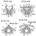
- JP2004-116357A (hereinafter referred to as Reference 1) discloses such air intake control valve as illustrated in Figs. 9A and 9B in which a gasket (seal member) 67 formed into a string shape and made of an elastic material is attached to an outer periphery of a frame (body) 62 holding a valve element.
- a gasket seal member
- a gap between the sealed surface 66f and the body 62 is sealed by the seal member 67 that is pressed against the sealed surface 66f of the partition wall.
- the seal member 67 includes a fitting portion 68 fitted to a seal groove 62D that is formed at the outer periphery of the body 62.
- the fitting portion 68 substantially includes a rectangular cross section.
- the seal member 67 also includes an end seal portion 69 vertically extending from the fitting portion 68 towards the sealed surface 66f.
- the end seal portion 69 substantially includes a semicircular cross section symmetric to a divided surface constituted by the body 62 so as to divide an inner portion of the surge tank into two portions.
- the end seal portion 69 is squashed towards the fitting portion 68 by the sealed surface 66f while the symmetric shape of the end seal portion 69 relative to the divided surface is maintained as illustrated in Fig. 9B .
- a rigidity to some extents may be required to the end seal portion 69. Therefore, an apex angle of a triangular-shaped cross section constituting the end seal portion 69 may be inhibited from having too acute angle and additionally the end seal portion 69 may be made of a material having relatively high rigidity.
- the fitting portion 68 of the seal member 67 is likely to disengage from the seal groove 62D formed at the outer periphery of the body 62 or to be partially pulled out in a direction where the body 62 is attached because of the high contact pressure, the frictional resistance, and the like acting between the sealed surface 66f and the end seal portion 69.
- the sealing ability of the end seal portion 69 may be deteriorated.
- the body 62 may be deformed by a reaction force that is generated at the body 62 by means of the end seal portion 69, which may lead to the air leakage between the body 62 and the fitting portion 68 of the seal member 67.
- the seal member 67 may have an arched shape in a cross section by including a groove portion 70 having a tunnel shape at a lower end of the fitting portion 68 to thereby reduce the reaction force generated at the fitting portion 68 of the seal member 67.
- an easy deformation is insufficient for the entire seal member 67.
- a large compression by a low load may be impossible and therefore an issue of an excessive load when the body 62 is inserted into the sealed surface 66f may not be effectively dissolved.
- JP63-156422U discloses an air intake control valve including two projections that serve as the end seal portion so as to extend in parallel to a divided surface constituted by a body.
- each of the projections vertically projects towards a sealed surface, which may also raise issues such as a difficulty in attaching the body to the sealed surface, the deterioration of the sealing ability because of the disengagement or the pull-out of a fitting portion of a seal member, an air leakage caused by the deformation of the body, or the like.
- US 2006/0016415 A1 discloses another engine air intake device.
- a need thus exists for a system comprising a surge tank and an air intake control valve being mounted to the surge tank that sufficiently restrains an air leakage between upper and lower chambers in a fully closed state of the air intake control valve while a contact pressure acting between a sealed surface and an end seal portion is sufficiently reduced so that a body is easily attached to the sealed surface, and a deterioration of a sealing ability based on a disengagement or a pull-out of a fitting portion of a seal member, an air leakage based on a deformation of the body, and the like are unlikely to occur).
- a system comprises a surge tank and an air intake control valve mounted thereto that includes a body extending to divide an inner portion of a surge tank of a multi-cylinder internal combustion engine into two portions, the body serving as a divided surface to divide the inner portion of the surge tank into the two portions, a valve element operated to rotate for opening and closing a fluid passage formed at the body, and a seal member sealing between a sealed surface of the surge tank and an outer periphery of the body, the seal member including a seal portion constituted by two contact portions that make contact with the sealed surface in a state where the two contact portions extend in directions opposite from each other relative to the divided surface.
- the two contact portions extend obliquely in an upward direction so as to be away from each other from an initial state before the seal member receives an external force.
- the two contact portions are bent and deformed so as to be easily positioned close to the body, thereby smoothly mounting the air intake control valve to the surge tank.
- a reaction force applied to the body from the seal member is small in the process of attaching the air intake control valve to the surge tank and after the air intake control valve is attached to the surge tank, the deformation of the body caused by the aforementioned reaction fore is restrained.
- the seal member includes a supported portion supported by the body and two intermediate portions extending from the supported portion to the sealed surface, and the two contact portions extend from the two intermediate portions respectively.
- the two intermediate portions in addition to the two contact portions are elastically deformed towards the body by the contact with the sealed surface in the case of attaching the air intake control valve to the surge tank.
- an insertion load is further reduced to thereby further smoothly mounting the air intake control valve to the surge tank.
- a fatigue resistance of the seal member increases because a stress amplitude at a base portion of each of the intermediate portions represents a half amplitude.
- the two intermediate portions serve as deformation portions that are initially elastically deformed by a contact with the sealed surface in a case of attaching the air intake control valve to the sealed surface.
- the two intermediate portions connecting the supported portion to the two contact portions are initially elastically deformed prior to the other portions by the contact between the contact portions and the sealed surface. Because the two contact portions are not easily deformed, only the tip ends of the two contact portions make contact with the sealed surface. As a result, a contact area of the seal member relative to the sealed surface is limited to portions in the vicinity of the tip ends of the two contact portions, which leads to a decrease of the insertion load. Productivity is improved and an investment in facility for a large insertion load of the air intake control valve is avoidable. Further, because of the decrease of the insertion load, a quality defect such as a dislocation or disengagement of the seal member when the air intake control valve is assembled to the surge tank is avoidable.
- the two intermediate portions and tip ends of the two contact portions serve as the deformation portions that are easily deformed by the contact with the sealed surface in the case of attaching the air intake control valve to the sealed surface.
- the two intermediate portions connecting the supported portion to the two contact portions, and the tip ends of the two contact portions are easily elastically deformed by the contact with the sealed surface while portions at base sides of the two contact portions and the like are not easily elastically deformed.
- the tip ends of the two contact portions make contact with the sealed surface.
- the contact area of the seal member relative to the sealed surface is minimized and the insertion load is recued, which may increase the productivity and avoid the investment in facility for the large insertion load of the air intake control valve.
- the two contact portions extend to gradually open outwardly towards the sealed surface before the air intake control valve is mounted to the surge tank.
- the two contact portions make contact with the sealed surface in such a manner that the two contact portions are gradually away from each other while being positioned closer to the sealed surface.
- one of the contact portions positioned close to either surge chamber having the higher pressure is pressed against the sealed surface by the air pressure, thereby maintaining the high sealing ability.
- the body includes a curved portion curved along the divided surface while the seal member includes a bent portion bent and deformed along the curved portion of the body so as to be mounted to the sealed surface, and wherein a distance between the two contact portions in the bent portion of the seal member varies in association with a decrease of a curvature radius of the curved portion in a state before the bent portion of the seal member is bent and deformed so as to be mounted to the sealed surface.
- the two contact portions may be folded down towards the body.
- an appropriate contact of the seal member relative to the sealed surface may not be obtained.
- the tip ends of the two contact portions are arranged to be close to each other or to be away from each other in association with the decrease of the curvature radius of the curved portion of the body in a sate before the seal member is bent and deformed.
- the two contact portions in the bent portion of the seal member are bent and deformed so that the seal member is mounted to the surge tank, the two contact portions are appropriately folded and bent towards the body. Then, the two contact portions in the bent portion of the seal member is positioned to be away from each other by a distance which is substantially the same as a distance by which the two contact portions in a portion other than the bent portion of the seal member is positioned to be away from each other. As a result, the appropriate contact of the two contact portions of the seal member relative to the sealed surface is obtained.
- the body includes a curved portion curved along the divided surface while the seal member includes a bent portion bent and deformed along the curved portion of the body so as to be mounted to the sealed surface, and wherein an extending length of each of the two contact portions increases in association with a decrease of a curvature radius of the curved portion in a state before the bent portion of the seal member is bent and deformed so as to be mounted to the sealed surface.
- the two contact portions may be folded down towards the body.
- the extending length of each of the two contact portions in the bent portion of the seal member may be longer than the extending length of each of the two contact portions in the portion other than the bent portion of the seal member in a state before the seal member is bent and deformed.
- the two contact portions are appropriately folded towards the body so that the extending length of each of the two contact portions in the bent portion of the seal member is substantially equal to the extending length of each of the two contact portions in the portion other than the bent portion of the seal member.
- the appropriate contact of the two contact portions of the seal member relative to the sealed surface is obtained.
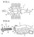
- FIG. 1 illustrates a relationship between an air intake system 1 for a V-type 6-cylinder engine (hereinafter simply referred to as an engine), and six cylinders C1, C2, C3, C4, C5, and C6 (hereinafter referred to as cylinders C1 to C6 when collectively described).
- the air intake system 1 includes an air intake passage 3 supplied with air taken in through an air filter, and a surge tank 5 disposed between the air intake passage 3 and the cylinders C1 to C6.
- a throttle valve 2 is provided at the air intake passage 3.
- the surge tank 5 is divided into first and second surge chambers 7a and 7b by means of a partition wall 6.
- the cylinders C1, C3, and C5 are connected to the first chamber 7a provided at an upper side in Fig. 1 via respective intake pipes 4.
- the cylinders C2, C4, and C6 are connected to the second surge chamber 7b provided at a lower side in Fig. 2 via the respective intake pipes 4.
- a resonance of a manifold air pressure is generated at a predetermined engine rotational range.
- Such resonance is generated in a case where a frequency (a resonance frequency) that is determined on a basis of a volume, a length, and the like of the surge tank 5 and/or the air intake passage 3 provided at an upstream side of the surge tank 5, for example, and an intake air frequency of the cylinders C1 to C6 match each other.
- a pressure at the air intake system 1 increases, which leads to a supercharging effect. Because of the supercharging effect, an intake air volume of each of the cylinders C1 to C6 increases to thereby improve an engine output.
- an air intake control valve 10 is provided at the air intake system 1 so as to achieve an open state where the first and second surge chambers 7a and 7b are connected to each other and a closed state where the first and second surge chambers 7a and 7b are disconnected to each other.
- the resonance frequency of the air intake system 1 changes.
- the air intake control valve 10 is appropriately controlled to open or close depending on an operation condition of the engine to thereby change the resonance frequency of the air intake system 1 and obtain the supercharging effect.
- the increase of the engine output at a wide range of the engine rotational range is achievable.
- the first surge chamber 7a provided at the upper side and the second surge chamber 7b provided at the lower side are connected to each other by means of a cutout 6p formed at a portion of the partition wall 6.
- the air intake control valve 10 that is enlarged so as to improve the supercharging effect is mounted on the cutout 6p.
- An actuator 40 for opening and closing the air intake control valve 10 may be an electrically controlled type so as to be driven by an electric signal sent from an ECU (an electronic control unit) that is mounted at a vehicle.
- the pressure is alternately generated at the first and second surge chambers 7a and 7b that are arranged next to each other via the partition wall 6 because the air intake is sequentially performed by the cylinders C1 to C6.
- a fluid leakage may occur between the cutout 6p and the air intake control valve 10 while the air intake control valve 10 is in the closed state, for example, an expected resonance frequency is not obtained at the air intake system 1, which leads to a deterioration of the supercharging effect.
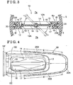
- the air intake control valve 10 includes a body 12 attached to the cutout 6p of the partition wall 6 and a valve element 14 supported by a shaft 15. Both ends of the shaft 15 are pivotally supported by respective portions of the body 12.
- the body 12 is formed into a frame shape extending along the cutout 6p of the partition wall 6.
- a fluid passage 10A is formed at an inner side of the frame shape of the body 12.
- a seal receiving portion 13 is formed at an inner peripheral surface of the body 12 so as to extend within the fluid passage 10A.
- the seal receiving portion 13 extends over a substantially entire inner periphery of the body 12.
- the closed position of the valve element 14 is illustrated by a solid line while the open position of the valve element 14 is illustrated by a chain double-dashed line.
- the valve element 14 includes a valve body 16 attached to the shaft 15 and formed into a resin-made plate shape, and an elastic seal member 17 arranged at a peripheral edge of the valve body 16 and made of rubber.
- the elastic seal member 17 includes an attachment portion 18 fitted to an outer periphery of the valve body 16 and a lip portion 19 projecting from a portion of a peripheral edge of the attachment portion 18 so as to incline close to a center of the valve element 14.
- the lip portion 19 is connected to a portion of an outer periphery of the attachment portion 18 so as to extend and incline towards the center of the valve element 14.
- the actuator 40 brings the valve element 14 to rotate so as to obtain the open state (open position) where the first and second surge chambers 7a and 7b are connected (i.e., the open state of the fluid passage 10A) and obtain the closed state (closed position) where the first and second surge chambers 7a and 7b are disconnected (i.e., the closed state of the fluid passage 10A).
- the lip portion 19 is pressed against the seal receiving portion 13 to thereby disconnect the first and second surge chambers 7a and 7b from each other.
- the air intake control valve 10 is inserted into an opening portion 5A formed at the surge tank 5 opposite from the air intake passage 3 so as to be fixed to the surge tank 5 by means of a bolt, for example, that is inserted into a through-hole formed at a flange 10F of the air intake control valve 10.
- a bolt for example
- an inner portion of the surge tank 5 is divided into two portions, i.e., the first surge chamber 7a and the second surge chamber 7b, by mean of the body 12 of the air intake control valve 10. That is, the body 12 serves as a divided surface to divide the inner portion of the surge tank 5 into the two portions.
- a sheet surface of Fig. 4 corresponds to the divided surface.
- an outer peripheral seal member (a gasket) 20 (serving as an example of a seal member) formed into a strip shape and made of rubber is attached to an outer periphery of the body 12.
- a gasket serving as an example of a seal member
- a gap between the body 12 and an end surface 6f (serving as an example of a sealed surface) of the cutout 6p of the surge tank 5 is filled with the outer peripheral seal member 20, which leads to a high sealability.
- the outer peripheral seal member 20 includes a center portion 20A attached to a tip end portion of the body 12 (i.e., a portion of the body 12 away from the flange 10F) and two side portions 20B extending from both ends of the center portion 20A.
- a center portion 20A attached to a tip end portion of the body 12 (i.e., a portion of the body 12 away from the flange 10F)
- two side portions 20B extending from both ends of the center portion 20A.
- ranges where the two side portions 20B are arranged are indicated by arrows E respectively.
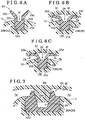
- Figs. 5A and 5B are a side view and a plan view of the outer peripheral seal member 20 respectively in which the two side portions 20B extend along the divided surface constituted by the body 12 so as to be linear relative to the center portion 20A.
- the center portion 20A in the side view and the plan view is formed so that a width thereof is larger than those of the two side portions 20B.
- the outer peripheral seal member 20 before being attached to the body 12 is substantially formed into a linear shape as illustrated in Figs. 5A and 5B . Then, the outer peripheral seal member 20 is attached to the body 12 in a state to be elastically deformed in a curved shape so as to conform to a shape of the body 12 as illustrated in Fig. 4 .
- the center portion 20A engages with the surge tank 5 so that a groove (a clearance) 24 formed at an outer periphery of the center portion 20A engages with an engagement projection 6Q that projects towards the opening portion 5A from the end surface 6f of the cutout 6p as illustrated in Fig. 7 .
- a projection such as the engagement projection 6Q is not formed at a portion of the end surface 6f positioned to face each of the two side portions 20B.
- a pair of first contact portions 23d basically formed into a Y-shape while having an opening as illustrated in Fig.
- contact portions such as the contact portions 23d are portions which are contactable with the end surface 6f in association with an increase of a pressure in each of the surge chambers 7a and 7b after the air intake control valve 10 is mounted to the surge tank 5 and the engine is started.
- a greater portion of the two side portions 20B is constituted by first pattern portions S1 each having a cross-sectional shape as illustrated in Fig. 5C and second pattern portions S2 each having a cross-sectional shape as illustrated in Fig. 5D .
- the first pattern portions S1 and the second pattern portions S2 are alternately arranged to one another.
- each of the first pattern portions S1 includes a first fitting portion 21d (serving as an example of a supported portion) fitted to a seal groove 12D (see Fig. 6A ) of the body 12 and substantially formed into a rectangular shape.
- the first pattern portion S1 also includes a pair of first intermediate portions 22d extending in parallel to each other towards the end surface 6f from both ends (i.e., right and left ends in Fig. 5C ) of the first fitting portion 21d, and the pair of first contact portions 23d extending so as to be away or opposite from each other relative to the divided surface constituted by the body 12 from ends (i.e., upper ends of the first intermediate portions 22d in Fig. 5C ) of the respective first intermediate portions 22d.
- the first contact portions 23d extend obliquely in an upward direction so as to be away from each other (i.e., extend obliquely in an upward and outward direction relative to the divided surface) in a symmetric manner.
- each of the second pattern portions S2 includes a second fitting portion 21f (serving as an example of the supported portion) fitted to the seal groove 12D of the body 12 and substantially formed into a rectangular shape.
- the second pattern portion S2 also includes a pair of second intermediate portions 22f extending in parallel to each other towards the end surface 6f from both ends (i.e., right and left ends in Fig. 5D ) of the second fitting portion 21f, and a pair of second contact portions 23f extending so as to be away or opposite from each other relative to the divided surface constituted by the body 12 from ends (i.e., upper ends of the second intermediate portions 22f in Fig. 5D ) of the respective second intermediate portions 22f.
- the second contact portions 23f extend obliquely in an upward direction so as to be away from each other (i.e., extend obliquely in an upward and outward direction relative to the divided surface) in a symmetric manner.
- Each of the first pattern portions S1 and each of the second pattern portions S2 basically include the same cross-sectional shape.
- the difference between the first and second pattern portions S1 and S2 is that padding portions 21A are formed at both sides (i.e., right and left sides in Fig. 5D ) of the second fitting portion 21f of the second pattern portion S2 so as to have a larger width than the first fitting portion 21d of the first pattern portion S1.
- a width of a portion of the seal groove 12D of the body 12 facing the two side portions 20B is constant over an entire length.
- the two side portions 20B engage with the body 12 in a state where the second fitting portion 21f of each of the second pattern portions S2 of which the width is sufficiently larger than the width of the seal groove 12D is press-fitted to the seal groove 12D.
- the width of the first fitting portion 21d of each of the first pattern portions S1 is formed to be slightly smaller than the width of the seal groove 12D. Therefore, the first fitting portion 21d engages with the seal groove 12D without the press-fitting.
- the outer peripheral seal member 20 is mounted to the body 12 in a state where the first fitting portions 21d of the first pattern portions S1 in addition to the second fitting portions 21f of the second pattern portions S2 are pressed against a bottom portion of the seal groove 12D, an air leakage via lower surfaces of the first and second fitting portions 21d and 21f is inhibited.
- the pair of first contact portions 23d extends so as to be away from each other relative to the divided surface constituted by the body 12, i.e., extends obliquely in an outward direction.
- the pair of second contact portions 23f extends so as to be away from each other relative to the divided surface, i.e., extends obliquely in the outward direction.
- the width of each of the first intermediate portions 22d and the first contact portions 23d is formed to be sufficiently smaller than the width of the first fitting portion 21d while the width of each of the second intermediate portions 22f and the second contact portions 23f is formed to be sufficiently smaller than the width of the second fitting portion 21d.
- the first intermediate portions 22d, the second intermediate portions 22f, the first contact portions 23d, and the second contact portions 23f are easily elastically deformed so as to be inclined towards the body 12 in respective directions based on the contact of the first intermediate portions 22d, the second intermediate portions 22f, the first contact portions 23d, and the second contact portions 23f relative to the end surface 6f.
- the air intake control valve 10 is smoothly inserted and mounted to the surge tank 5.
- the groove 24 having a sufficient width is formed between each of the pair of first intermediate portions 22d and the pair of second intermediate portions 22f.
- the width of each of the pair of first intermediate portions 22d and the pair of second intermediate portions 22f (each serving as an example of a deformation portion) is specified to be smaller than the width of a base portion of each of the pair of first contact portions 23d and the pair of second contact portions 23f. That is, each of the pair of first intermediate portions 22d and the pair of second intermediate portions 22f has a low rigidity.
- each of the pair of first contact portions 23d and the pair of second contact portions 23f has a high rigidity because of being gradually widen from a tip end portion to the base portion.
- the pair of first contact portions 23d and the pair of second contact portions 23f are not easily deformed. Therefore, in a case where the air intake control valve 10 is inserted and mounted to the surge tank 5, the pair of first intermediate portions 22d and the pair of second intermediate portions 22f are elastically deformed by making contact with the end surface 6f prior to the other members. The pair of first contact portions 23d and the pair of second contact portions 23f are not easily deformed except for the tip end portions.
- the contact of the outer peripheral seal member 20 relative to the end surface 6f in a case where the air intake control valve 10 is inserted and mounted to the surge tank 5 is limited to portions at inner sides of the first and second contact portions 23d and 23f in the vicinity of the tip end portions thereof. That is, a contact area of the outer peripheral seal member 20 relative to the end surface 6f is minimized and therefore the insertion load of the air intake control valve 10 decreases, which leads to an easy insertion and mounting of the air intake control valve 10. As a result, productivity increases, which may avoid an investment in facility for a large insertion load of the air intake control valve 10. In addition, because of the decrease of the insertion load, a quality defect such as a dislocation of the outer peripheral seal member 20 when the air intake control valve 10 is assembled to the surge tank 5 is avoidable.
- the first and second contact portions 23d and 23f (each serving as an example of a seal portion) are pressed against the end surface 6f of the partition wall 6 by means of a relatively weak restoring force of the first and second intermediate portions 22d and 22f.
- an air intake pulsation is alternately applied to the first and second surge chambers 7a and 7b.
- a greater part of the first contact portions 23d (and the second contact portions 23f) facing the first and second surge chambers 7a and 7b is strongly pressed against the cutout 6p (the end surface 6f).
- the sealing ability is automatically enhanced and the high air tightness is maintained.
- the width of each of the tip end portions of the first and second contact portions 23d and 23f (each serving as an example of the deformation portion) is relatively small so that the first and second contact portions 23d and 23f are easily elastically deformed by the contact with the cutout 6p (the end surface 6f).
- Bottom plane portions of the grooves 24 respectively provided between the first intermediate portions 22d and between the second intermediate portions 22f are each formed into a solid shape while including a large amount of rubber so as to have a large rigidity. Accordingly, in a case where the outer peripheral seal member 20 is assembled on the seal groove 12D of the body 12, the load is applied to the bottom plane portions of the grooves 24 so that a damage, breakage or the like on each of the first and second contact portions 23c, 23d, the first and second intermediate portions 22d, 22f, and the like is inhibited.
- Both side corners (i.e., right and left corners in Figs. 6A, 6B, and 6C ) of each of the grooves 24 are formed into round cross sectional shapes each including an arc relative to a center of a void of the groove 24.
- a stress generated when each of the first and second intermediate portions 22d and 22f is deformed is dispersed.
- a fatigue resistance of each of the first and second contact portions 23d, 23f, and the first and second intermediate portions 22d and 22f increases.
- a reduction in an amount of rubber of the outer peripheral seal member 20 and a cost reduction thereof are achieved as well as a light-weight of the outer peripheral seal member 20 as a whole.
- a curvature radius of each curved portion of the body 12 positioned to face a portion of each of the two side portions 20B in the vicinity of the center portion 20A is small.
- the bent portions of the two side portions 20B in the vicinity of the center portion 20A are bent and deformed so as to conform to the curvature radius of the curved portions of the body 12.
- the first and second contact portions 23d and 23f may be folded down toward the body 12, which may inhibit the appropriate contact relative to the cutout 6p after the air intake control valve 10 is mounted to the surge tank 5.
- the tip ends of the pair of first contact portions 23d are arranged so as to be close to each other in association with the decrease of the curvature radius.
- the tip ends of the pair of second contact portions 23f are arranged so as to be close to each other in association with the decrease of the curvature radius.
- the first contact portions 23d and the second contact portions 23f in the bent portions of the two side portions 20B are appropriately bent or inclined towards the body 12 so that a distance between the tip ends of the first contact portions 23d and a distance between the tip ends of the second contact portions 23f in the bent portions of the two side portions 20B are each substantially equal to a distance between the contact portions 23d or 23f in portions other than the bent portions (i.e., straight portions) of the two side portion 20B.
- the appropriate contact of the outer peripheral seal member 20 relative to the end surface 6f is achieved.
- an angle formed between the first contact portions 23d and an angle formed between the second contact portions 23f are each defined to be small.
- the aforementioned angles may not be changed and a distance between the first intermediate portions 22d and a distance between the second intermediate portions 22f may be reduced.
- an extending length of each of the first contact portions 23d and the second contact portions 23f in the bent portions of the two side portions 20B may be longer than the extending length of each of the first and second contact portions 23d and 23f in the straight portions of the two side portions 20B in a state before the outer peripheral seal member 20 is bent and deformed.
- fourth pattern portions S4 are provided at most end portions of the two side portions 20B respectively.
- Each of the fourth pattern portions S4 is formed into a cross-sectional shape similar to that of the second pattern portion S2 but the groove 24 and a gap (a space) between the second contact portions 23f are eliminated.
- third pattern portions S3 are provided, each of which is arranged between two of the first pattern portions S1 arranged close to the center of the outer peripheral seal member 20 relative to the fourth pattern portions S4.
- Each of the third pattern portions S3 includes a third fitting portion 21e of which the width is larger than the second fitting portion 21f of the second pattern portion S2, a pair of third intermediate portions 22e, and a pair of third contact portions 23e.
- the third fitting portion 21e serves as an example of the supported portion while the third contact portions 23e each serves as an example of the seal portion.
- the third pattern portions S3 serve as engagement portions inserted and fitted to respective lock grooves 12E (see Fig. 4 ) formed at two portions of the body 12 in the vicinity of a base portion thereof (i.e., a portion of the body 12 close to the flange 10F) as illustrated in Fig. 4 .
- the lock grooves 12E are arranged slightly closer to the flange 10F as compared to a distance from a center of the outer peripheral seal member 20 (which corresponds to a 5H-5H plane in Fig. 5A ) in a longitudinal direction thereof to each of the third pattern portions S3 in a state where the external force is not applied to the outer peripheral seal member 20.
- Hardness and strength of a rubber material constituting the outer peripheral seal member 20 are defined to be relatively high so as to respond to alcohol fuel.
- a reaction force (a rubber reaction force) generated at portions of the outer peripheral seal member 20 attached to corner portions of the body 12 each having a U-shape is relatively large so as to return to an original linear shape.
- the positions of the lock grooves 12E are defined in the aforementioned manner as the tightening and fitting means, thereby effectively restraining a lifting-up, disengagement, or the like of the outer peripheral seal member 20 by the rubber reaction force, because of a tensile force maintained at the outer peripheral seal member 20 after the outer peripheral seal member 20 is attached to the body 12.
- the tightening and fitting means may be provided between the both ends of the center portion 20A and the body 12.
- the tightening and fitting means provided at four portions or more of the outer peripheral seal member 20 may effectively inhibit the disengagement of the outer peripheral seal member 20 from the body 12 caused by the rubber reaction force of the outer peripheral seal member 20. Further, the tightening and fitting means provided at four or more portions in an asymmetrical manner may inhibit a wrong assembly.
- the positions of the lock groves 12E are specified in the aforementioned manner so that the first intermediate portions 22d of the first pattern portions S1 engage with the tip end portion of the body 12, and then the third pattern portions S3 are inserted and fitted to the lock grooves 12E. Then, the second fitting portions 21f of the second pattern portions S2 are inserted and fitted to the seal groove 12D one by one, which leads to an easy assembly of the outer peripheral seal member 20.
- the fourth pattern portions S4 provided at the most end portions of the outer peripheral seal member 20 respectively form ribs (specifically, each of the fourth pattern portions S4 has a rib portion 25) while having no grooves or spaces, thereby being connected to the respective adjacent first pattern portions S1.
- the fourth pattern portions S4 restrain the air leakage from one of the first and second surge chambers 7a and 7b to the other of the first and second surge chambers 7a and 7b via spaces such as those between the contact portions and between the intermediate portions.
- the fourth pattern portions S4 constituting the ribs may not be only provided at the both end portions of the outer peripheral seal member 20 but also provided at any other portions of the outer peripheral seal member 20.
- ribs i.e., the fourth pattern portions S4 restrain the contact portions 23d, 23e and 23f from being inclined or folded because of a pressure difference between the first and second surge chambers 7a and 7b. As a result, the high sealing ability is maintained even under a pressure pulsation.
- a groove having a tunnel shape may be intermittently formed at the bottom surface of the outer peripheral seal member 20. As a result, the reduction of the amount of rubber and the light-weight of the outer peripheral seal member 20 as a whole are further enhanced.
- a distance between the fourth pattern portion S4 forming the rib and the adjacent third pattern portion S3 is specified to be slightly longer than a length of a corresponding portion of the groove 12D formed at the body 12 in a state where the outer peripheral seal member 20 is in the linear shape. Therefore, both end surfaces of the both end portions of the outer peripheral seal member 20 are elastically pressed against the end surface of the flange 10F of the body 12. The air leakage between the first and second surge chambers 7a and 7b at the both end portions of the outer peripheral seal member 20 is inhibited, which ensures the further high sealing ability.
- the groove 24 formed at a fifth pattern portion S5 that occupies a majority of the length of the center portion 20A includes a pair of side surface portions 25i engaging with the engagement projection 6Q that projects from the body 12.
- the fifth pattern portion S5 includes a center projection 20T having an arc-shape in a plan view and formed at a center of the outer peripheral seal member 20 in the longitudinal direction thereof.
- Fig. 5H illustrates a cross section of a portion corresponding to the center projection 20T.
- An area sandwiched between two dashed lines in Fig. 5H illustrates a cross-sectional shape of the fifth pattern portion S5 not provided with the center projection 20T.
- a wide-shaped portion is formed at the seal groove 12D of the body 12 so as to correspond to the center projection 20T.
- the center projection 20T engages with the wide-shaped portion of the body 12 so as to perform a centering of the outer peripheral seal member 20 in the longitudinal direction.
- Sixth pattern portions S6 smoothly connect the fifth pattern portion S5 having the wide shape to the two side portions 20B each having the narrow shape.
- the engagement projection 6Q is inserted and fitted to the groove 24 of each of the sixth pattern portions S6 so that the sixth pattern portion S6 engages with the engagement projection 6Q in the vicinity of a boundary between intermediate portions 22g and contact portions 23g of the sixth pattern portion S6. Accordingly, the fifth pattern portion S5 and the sixth pattern portions S6 are fitted to or engage with the engagement projection 6Q to thereby appropriately and correctly position the center portion 20A relative to the body 12 in a direction perpendicular to the divided surface constituted by the body 12.
- a vertical vibration or a rotational vibration of the body 12 in the vicinity of the tip end portion thereof is large because of a vibration or a pulsation pressure difference applied to the valve element 14 or the body 12 that supports the valve element 14.
- the engagement projection 6Q is fitted to the grooves 24 each having a U-shape that are formed at the center portion 20A of the outer peripheral seal member 20, thereby restraining the vibration of the body 12.
- the air intake control valve 10 is mounted to the surge tank 5
- a self-centering of the air intake control valve 10 relative to the cutout 6p of the surge tank 5 is achieved because of the fitting between the grooves 24 and the engagement projection 6Q.
- the outer peripheral seal member 20 is provided, no direct contact is obtained between the body 12 and the end surface 6f, thereby inhibiting a malfunction such as an interfering noise.
- the pair of first contact portions 23d of each of the first pattern portions S1 may be arranged in parallel to each other
- the pair of second contact portions 23f of each of the second pattern portions S2 may be arranged in parallel to each other
- the third contact portions 23e of each of the third pattern portions S3 may be arranged in parallel to each other as in the same way as the pair of first intermediate portions 22d, the pair of second intermediate portions 22f, and the pair of third intermediate portions 22e while the contact portions 23d, 23e, and 23f are each in a natural state so as not to receive the external force.
- the first to third contact portions 23d, 23f, and 23e may be deformed to be positioned closer to the body 12 by hand or by a jig so as to be mounted to the body 12 of the air intake control valve 10.
- the single first intermediate portion 22d may extend from the first fitting portion 21d
- the single second intermediate portion 22f may extend from the second fitting portion 21f
- the single third intermediate portion 22e may extend from the third fitting portion 21e.
- the pair of first contact portions 23d may extend from an end of the single first intermediate portion 22d in a direction opposite from each other relative to the divided surface constituted by the body 12.
- the pair of second contact portions 23f may extend from an end of the single second intermediate portion 22f in a direction opposite from each other relative to the divided surface constituted by the body 12.
- the pair of third contact portions 23e may extend from an end of the single third intermediate portion 22e in a direction opposite from each other relative to the divided surface constituted by the body 12.
- one of a pair of intermediate portions 52 and one of a pair of contact portions 53, and the other of the pair of intermediate portions 52 and the other of the pair of contact portions 53 may extend from both side edges at an upper portion of a fitting portion 51 so as to form an arc shape towards a center line of the outer peripheral seal member 20.
- a projection 6R is formed at the end surface 6f of the partition wall 6 so as to extend along the two side portions 20B.
- outer side surfaces of the pair of contact portions 53 are pressed against the end surface 6f as illustrated in Fig. 8B .
- the ends of the pair of contact portions 53 are pressed against corners each formed between a side surface of the projection 6R and the end surface 6f, thereby maintaining the air sealed state.
- the tip ends of the first contact portions 23d are arranged to be close to each other in association with the increase of the curvature radius of the curved portions of the body 12 in a state before the outer peripheral seal member 20 is bent and deformed.
- the tip ends of the second contact portions 23f are arranged to be close to each other in association with the increase of the curvature radius of the curved portions of the body 12 in a state before the outer peripheral seal member 20 is bent and deformed.
- the tip ends of the second contact portions 23f are arranged to be close to each other in association with the increase of the curvature radius of the curved portions of the body 12 in a state before the outer peripheral seal member 20 is bent and deformed.
- the tip ends of the contact portions 53 may be arranged to be away from each other in association with the decrease of the curvature radius in a state before the outer peripheral seal member 20 is bent and deformed. Then, when the two side portions 20B are bent and deformed so as to mount the outer peripheral seal member 20 to the body 12, the contact portions 53 are appropriately bent towards the body 12. As a result, a distance between the two contact portions 53 in the bent portions of the two side portions 20B is substantially equal to a distance between the two contact portions 53 in the straight portions of the two side portions 20B, thereby obtaining an appropriate contact state relative to the end surface 6f.
Landscapes
- Engineering & Computer Science (AREA)
- Chemical & Material Sciences (AREA)
- Combustion & Propulsion (AREA)
- Mechanical Engineering (AREA)
- General Engineering & Computer Science (AREA)
- Manufacturing & Machinery (AREA)
- Characterised By The Charging Evacuation (AREA)
Claims (7)
- System, mit:einem Ausgleichsbehälter (5) einer Mehrzylinderbrennkraftmaschine, undeinem Lufteinlasssteuerventil (10), das an dem Ausgleichsbehälter (5) montiert ist,wobei das Lufteinlasssteuerventil (10) aufweist:einen Körper (12), der sich zum Teilen eines Innenbereichs des Ausgleichbehälters (5) einer Mehrzylinderbrennkraftmaschine in zwei Bereiche erstreckt, wobei der Körper (12) als eine Teilungsfläche zum Teilen des Innenbereichs des Ausgleichbehälters (5) in zwei Bereiche dient;ein Ventilelement (14), das dazu angepasst ist, zum sich Drehen zum Öffnen und Schließen eines Fluiddurchgangs (10A), der an dem Körper (12) ausgebildet ist, betätigt zu werden; undein Dichtbauteil (20), das zwischen einer gedichteten Fläche (6f) des Ausgleichbehälters (5) und einem Außenumfang des Körpers (12) abdichtet, wenn das Lufteinlasssteuerungsventil (10) an dem Ausgleichsbehälter (5) montiert ist, wobei das Dichtbauteil (20) einen Dichtbereich (23d, 23f, 23e) aufweist, der durch zwei Berührbereiche (23d, 23f, 23e, 53) gebildet wird, die eine Berührung mit der gedichteten Fläche (6f) in einem Zustand herstellen, in dem die zwei Berührbereiche (23d, 23f, 23e, 53) sich in Richtungen entgegengesetzt zueinander relativ zu der Teilungsfläche erstrecken, bei demder Berührbereich (23d, 23f, 23e, 53), der auf den Bereich des Ausgleichsbehälters (5) zeigt, der einen höheren Druck als der andere aus den zwei Bereichen des Ausgleichbehälters (5) aufweist, dazu angepasst ist, durch Wirkung des höheren Luftdrucks gegen die abgedichtete Fläche (6f) gepresst zu werden.
- System nach Anspruch 1, bei dem das Dichtbauteil (20) einen abgestützten Bereich (21d, 21f, 21e, 51), der durch den Körper (21) abgestützt wird, und zwei Zwischenbereiche (22d, 22f, 22e, 52), die sich von dem abgestützten Bereich (21d, 21f, 21e, 51) zu der abgedichteten Fläche (6f) erstrecken, und die zwei Berührbereiche (23d, 23e, 23f, 53), die sich jeweils von den zwei Zwischenbereichen (22d, 22f, 22e, 52) erstrecken, aufweist.
- System nach Anspruch 2, bei dem die zwei Zwischenbereiche (22d, 22f) als Deformationsbereiche dienen, die anfangs elastisch durch eine Berührung mit der abgedichteten Fläche (6f) in einem Fall eines Befestigens des Lufteinlasssteuerungsventils (10) an der abgedichteten Fläche (6f) deformiert werden.
- System nach Anspruch 2, bei dem die zwei Zwischenbereiche (22d, 22f) und Spitzenenden der zwei Berührbereiche (23d, 23f) als die Deformationsbereiche dienen, die einfach durch die Berührung mit der abgedichteten Fläche (6f) in dem Fall eines Befestigens des Lufteinlasssteuerungsventils (10) an der abgedichteten Fläche (6f) deformiert werden.
- System nach einem der Ansprüche 1 bis 4, bei dem die zwei Berührbereiche (23d, 23e, 23f) sich so erstrecken, dass sie sich graduell nach außen gerichtet zu der abgedichteten Fläche (6f) hin öffnen, bevor das Lufteinlasssteuerungsventil (10) an dem Ausgleichsbehälter (5) montiert wird.
- System nach einem der Ansprüche 1 bis 5, bei dem der Körper (12) einen gekrümmten Bereich aufweist, der entlang der Teilungsfläche gekrümmt ist, während das Dichtungsbauteil (20) einen gebogenen Bereich aufweist, der entlang des gekrümmten Bereichs des Körpers (12) so gebogen und deformiert wird, dass er an der abgedichteten Fläche (6f) montiert wird, und bei dem ein Abstand zwischen den zwei Berührbereichen (23d, 23f) in dem gebogenen Bereich des Dichtbauteils (20) sich in Verknüpfung mit einem Verringern eines Krümmungsradius des gekrümmten Bereichs verändert, in einem Zustand, bevor der gebogene Bereich des Dichtbauteils (20) so gebogen und deformiert wird, dass er an der gedichteten Fläche (6f) montiert ist.
- System nach einem der Ansprüche 1 bis 6, bei dem der Körper (12) einen gekrümmten Bereich aufweist, der entlang der Teilungsfläche gekrümmt ist, während das Dichtbauteil (20) einen gebogenen Bereich aufweist, der entlang des gekrümmten Bereichs des Körpers (12) so gebogen und deformiert wird, dass er an der abgedichteten Fläche (6f) montiert wird, und bei dem eine Erstreckungslänge von jedem der zwei Berührbereiche (23d, 23f) in Verknüpfung mit einer Verringerung eines Krümmungsradius des gekrümmten Bereichs ansteigt, in einem Zustand, bevor der gebogene Bereich des Dichtbauteils (20) so gebogen und deformiert wird, dass er an der gedichteten Fläche (6f) montiert ist.
Applications Claiming Priority (1)
| Application Number | Priority Date | Filing Date | Title |
|---|---|---|---|
| JP2010266752A JP5725326B2 (ja) | 2010-11-30 | 2010-11-30 | 吸気制御弁 |
Publications (3)
| Publication Number | Publication Date |
|---|---|
| EP2458192A1 EP2458192A1 (de) | 2012-05-30 |
| EP2458192B1 EP2458192B1 (de) | 2014-03-26 |
| EP2458192B2 true EP2458192B2 (de) | 2017-11-29 |
Family
ID=45375168
Family Applications (1)
| Application Number | Title | Priority Date | Filing Date |
|---|---|---|---|
| EP11189507.4A Active EP2458192B2 (de) | 2010-11-30 | 2011-11-17 | Lufteinlass-Steuerventil |
Country Status (4)
| Country | Link |
|---|---|
| US (1) | US8955484B2 (de) |
| EP (1) | EP2458192B2 (de) |
| JP (1) | JP5725326B2 (de) |
| CN (1) | CN102536422B (de) |
Families Citing this family (5)
| Publication number | Priority date | Publication date | Assignee | Title |
|---|---|---|---|---|
| JP5641361B2 (ja) | 2011-12-14 | 2014-12-17 | アイシン精機株式会社 | バタフライバルブの気密保持構造 |
| US9121375B2 (en) | 2012-11-01 | 2015-09-01 | Aisin Seiki Kabushiki Kaisha | Air intake control valve and air intake apparatus |
| JP2014152618A (ja) * | 2013-02-05 | 2014-08-25 | Denso Corp | 吸気装置 |
| JP6554949B2 (ja) * | 2015-07-07 | 2019-08-07 | アイシン精機株式会社 | 吸気装置および弁体 |
| KR20170025336A (ko) * | 2015-08-28 | 2017-03-08 | 두산인프라코어 주식회사 | 이물질 유입방지 실 및 이를 포함하는 건설기계 |
Citations (6)
| Publication number | Priority date | Publication date | Assignee | Title |
|---|---|---|---|---|
| US2470925A (en) † | 1946-01-16 | 1949-05-24 | Crane Co | Piston seal for flush valves |
| US3184213A (en) † | 1962-10-08 | 1965-05-18 | Acf Ind Inc | Seat for top entry ball valve |
| US4337956A (en) † | 1980-12-30 | 1982-07-06 | American Sterilizer Company | Double lip seal with pressure compensation |
| DE10256688A1 (de) † | 2001-12-04 | 2003-06-26 | Aisan Ind | Klappenventil |
| DE10258068A1 (de) † | 2001-12-19 | 2003-07-03 | Aisan Ind | Saugrohr |
| DE102004050094A1 (de) † | 2003-10-15 | 2005-05-25 | Aisan Kogyo K.K., Obu | Ventileinrichtungen zum Steuern und Regeln der Strömung von Einlassluft |
Family Cites Families (11)
| Publication number | Priority date | Publication date | Assignee | Title |
|---|---|---|---|---|
| GB933588A (en) | 1960-03-03 | 1963-08-08 | Lester Frank Dalton | Double lip seal ring |
| JPH0639052Y2 (ja) | 1987-04-02 | 1994-10-12 | トヨタ自動車株式会社 | 多気筒内燃機関の吸気装置 |
| US4794886A (en) * | 1987-04-01 | 1989-01-03 | Toyota Jidosha Kabushiki Kaisha | Intake device of an internal combustion engine |
| JPH07310828A (ja) * | 1994-05-18 | 1995-11-28 | Miura Co Ltd | 密閉容器用パッキン |
| JP3820924B2 (ja) * | 2001-06-20 | 2006-09-13 | トヨタ自動車株式会社 | 内燃機関の可変吸気装置及びその製造方法 |
| JP4053393B2 (ja) * | 2002-09-25 | 2008-02-27 | 愛三工業株式会社 | 吸気制御弁 |
| JP2004204792A (ja) * | 2002-12-26 | 2004-07-22 | Aisan Ind Co Ltd | 内燃機関の吸気装置 |
| US20050073110A1 (en) | 2003-10-07 | 2005-04-07 | James Armour | Neck seal for rolling mill oil film bearing |
| US7131416B2 (en) * | 2004-07-22 | 2006-11-07 | Nissan Motor Co., Ltd. | Engine air intake device |
| EP2063082B1 (de) | 2007-06-04 | 2009-12-30 | Honda Motor Co., Ltd. | Ansaugsteuerungssystem für einen Motor |
| JP4719716B2 (ja) * | 2007-06-04 | 2011-07-06 | 本田技研工業株式会社 | エンジンの吸気制御装置 |
-
2010
- 2010-11-30 JP JP2010266752A patent/JP5725326B2/ja active Active
-
2011
- 2011-11-17 EP EP11189507.4A patent/EP2458192B2/de active Active
- 2011-11-22 US US13/302,495 patent/US8955484B2/en active Active
- 2011-11-30 CN CN201110389586.1A patent/CN102536422B/zh active Active
Patent Citations (6)
| Publication number | Priority date | Publication date | Assignee | Title |
|---|---|---|---|---|
| US2470925A (en) † | 1946-01-16 | 1949-05-24 | Crane Co | Piston seal for flush valves |
| US3184213A (en) † | 1962-10-08 | 1965-05-18 | Acf Ind Inc | Seat for top entry ball valve |
| US4337956A (en) † | 1980-12-30 | 1982-07-06 | American Sterilizer Company | Double lip seal with pressure compensation |
| DE10256688A1 (de) † | 2001-12-04 | 2003-06-26 | Aisan Ind | Klappenventil |
| DE10258068A1 (de) † | 2001-12-19 | 2003-07-03 | Aisan Ind | Saugrohr |
| DE102004050094A1 (de) † | 2003-10-15 | 2005-05-25 | Aisan Kogyo K.K., Obu | Ventileinrichtungen zum Steuern und Regeln der Strömung von Einlassluft |
Also Published As
| Publication number | Publication date |
|---|---|
| JP2012117422A (ja) | 2012-06-21 |
| EP2458192B1 (de) | 2014-03-26 |
| US20120132169A1 (en) | 2012-05-31 |
| CN102536422A (zh) | 2012-07-04 |
| US8955484B2 (en) | 2015-02-17 |
| EP2458192A1 (de) | 2012-05-30 |
| JP5725326B2 (ja) | 2015-05-27 |
| CN102536422B (zh) | 2015-04-08 |
Similar Documents
| Publication | Publication Date | Title |
|---|---|---|
| EP2458192B2 (de) | Lufteinlass-Steuerventil | |
| US8714522B2 (en) | Fluid control valve | |
| US8136819B2 (en) | Sealing structure and gasket | |
| EP2489865A1 (de) | Verfahren zur befestigung eines abdeckungselements und befestigungsstruktur für eine kopfabdeckung | |
| US20140116372A1 (en) | Gasket, throttle body | |
| US20100037848A1 (en) | Valve cover with decoupled nvh isolation and sealing features | |
| US10533526B2 (en) | Connection structure of intake pipe | |
| CN110939534A (zh) | 空气净化器组件 | |
| US20090007874A1 (en) | Air intake device for multi-cylinder internal combustion engine | |
| JP5995775B2 (ja) | 樹脂製カバーの取付構造 | |
| US9683530B2 (en) | Air intake apparatus and manufacturing method of air intake apparatus | |
| JP5811760B2 (ja) | 燃料ポンプの取付構造 | |
| JP6064885B2 (ja) | ガスケット、エンジンの排気系部品取付構造、及びガスケットの取付け方法 | |
| CN101008341A (zh) | 用于内燃机的可变进气装置 | |
| JP6870345B2 (ja) | 吸気装置の取付構造、吸気装置の取付方法および樹脂部材の締結構造 | |
| CN110939533A (zh) | 空气净化器组件 | |
| JP7174544B2 (ja) | 吸気マニホルド | |
| US20090194055A1 (en) | Variable intake apparatus for internal combustion engine | |
| JP2011190698A (ja) | スロットル弁装置 | |
| JP4500638B2 (ja) | サージタンク | |
| JPS609481Y2 (ja) | 内燃機関のインテ−クマニホルド取付装置 | |
| JP7040138B2 (ja) | 吸気装置 | |
| JP6528811B2 (ja) | エンジンのチェーンカバー構造 | |
| JP6234830B2 (ja) | 部材の結合構造 | |
| JP2000220549A (ja) | 縦置式内燃機関のポンプ駆動機構 |
Legal Events
| Date | Code | Title | Description |
|---|---|---|---|
| PUAI | Public reference made under article 153(3) epc to a published international application that has entered the european phase |
Free format text: ORIGINAL CODE: 0009012 |
|
| AK | Designated contracting states |
Kind code of ref document: A1 Designated state(s): AL AT BE BG CH CY CZ DE DK EE ES FI FR GB GR HR HU IE IS IT LI LT LU LV MC MK MT NL NO PL PT RO RS SE SI SK SM TR |
|
| AX | Request for extension of the european patent |
Extension state: BA ME |
|
| 17P | Request for examination filed |
Effective date: 20120703 |
|
| 17Q | First examination report despatched |
Effective date: 20121005 |
|
| GRAP | Despatch of communication of intention to grant a patent |
Free format text: ORIGINAL CODE: EPIDOSNIGR1 |
|
| INTG | Intention to grant announced |
Effective date: 20131126 |
|
| GRAS | Grant fee paid |
Free format text: ORIGINAL CODE: EPIDOSNIGR3 |
|
| GRAA | (expected) grant |
Free format text: ORIGINAL CODE: 0009210 |
|
| AK | Designated contracting states |
Kind code of ref document: B1 Designated state(s): AL AT BE BG CH CY CZ DE DK EE ES FI FR GB GR HR HU IE IS IT LI LT LU LV MC MK MT NL NO PL PT RO RS SE SI SK SM TR |
|
| REG | Reference to a national code |
Ref country code: GB Ref legal event code: FG4D |
|
| REG | Reference to a national code |
Ref country code: CH Ref legal event code: EP |
|
| REG | Reference to a national code |
Ref country code: AT Ref legal event code: REF Ref document number: 659142 Country of ref document: AT Kind code of ref document: T Effective date: 20140415 |
|
| REG | Reference to a national code |
Ref country code: IE Ref legal event code: FG4D |
|
| REG | Reference to a national code |
Ref country code: DE Ref legal event code: R096 Ref document number: 602011005722 Country of ref document: DE Effective date: 20140515 |
|
| PG25 | Lapsed in a contracting state [announced via postgrant information from national office to epo] |
Ref country code: LT Free format text: LAPSE BECAUSE OF FAILURE TO SUBMIT A TRANSLATION OF THE DESCRIPTION OR TO PAY THE FEE WITHIN THE PRESCRIBED TIME-LIMIT Effective date: 20140326 Ref country code: NO Free format text: LAPSE BECAUSE OF FAILURE TO SUBMIT A TRANSLATION OF THE DESCRIPTION OR TO PAY THE FEE WITHIN THE PRESCRIBED TIME-LIMIT Effective date: 20140626 |
|
| REG | Reference to a national code |
Ref country code: AT Ref legal event code: MK05 Ref document number: 659142 Country of ref document: AT Kind code of ref document: T Effective date: 20140326 |
|
| REG | Reference to a national code |
Ref country code: NL Ref legal event code: VDEP Effective date: 20140326 |
|
| REG | Reference to a national code |
Ref country code: LT Ref legal event code: MG4D |
|
| PG25 | Lapsed in a contracting state [announced via postgrant information from national office to epo] |
Ref country code: SE Free format text: LAPSE BECAUSE OF FAILURE TO SUBMIT A TRANSLATION OF THE DESCRIPTION OR TO PAY THE FEE WITHIN THE PRESCRIBED TIME-LIMIT Effective date: 20140326 Ref country code: FI Free format text: LAPSE BECAUSE OF FAILURE TO SUBMIT A TRANSLATION OF THE DESCRIPTION OR TO PAY THE FEE WITHIN THE PRESCRIBED TIME-LIMIT Effective date: 20140326 |
|
| PG25 | Lapsed in a contracting state [announced via postgrant information from national office to epo] |
Ref country code: HR Free format text: LAPSE BECAUSE OF FAILURE TO SUBMIT A TRANSLATION OF THE DESCRIPTION OR TO PAY THE FEE WITHIN THE PRESCRIBED TIME-LIMIT Effective date: 20140326 Ref country code: LV Free format text: LAPSE BECAUSE OF FAILURE TO SUBMIT A TRANSLATION OF THE DESCRIPTION OR TO PAY THE FEE WITHIN THE PRESCRIBED TIME-LIMIT Effective date: 20140326 Ref country code: RS Free format text: LAPSE BECAUSE OF FAILURE TO SUBMIT A TRANSLATION OF THE DESCRIPTION OR TO PAY THE FEE WITHIN THE PRESCRIBED TIME-LIMIT Effective date: 20140326 |
|
| PG25 | Lapsed in a contracting state [announced via postgrant information from national office to epo] |
Ref country code: IS Free format text: LAPSE BECAUSE OF FAILURE TO SUBMIT A TRANSLATION OF THE DESCRIPTION OR TO PAY THE FEE WITHIN THE PRESCRIBED TIME-LIMIT Effective date: 20140726 Ref country code: EE Free format text: LAPSE BECAUSE OF FAILURE TO SUBMIT A TRANSLATION OF THE DESCRIPTION OR TO PAY THE FEE WITHIN THE PRESCRIBED TIME-LIMIT Effective date: 20140326 Ref country code: CY Free format text: LAPSE BECAUSE OF FAILURE TO SUBMIT A TRANSLATION OF THE DESCRIPTION OR TO PAY THE FEE WITHIN THE PRESCRIBED TIME-LIMIT Effective date: 20140326 Ref country code: CZ Free format text: LAPSE BECAUSE OF FAILURE TO SUBMIT A TRANSLATION OF THE DESCRIPTION OR TO PAY THE FEE WITHIN THE PRESCRIBED TIME-LIMIT Effective date: 20140326 Ref country code: BG Free format text: LAPSE BECAUSE OF FAILURE TO SUBMIT A TRANSLATION OF THE DESCRIPTION OR TO PAY THE FEE WITHIN THE PRESCRIBED TIME-LIMIT Effective date: 20140626 Ref country code: BE Free format text: LAPSE BECAUSE OF FAILURE TO SUBMIT A TRANSLATION OF THE DESCRIPTION OR TO PAY THE FEE WITHIN THE PRESCRIBED TIME-LIMIT Effective date: 20140326 Ref country code: RO Free format text: LAPSE BECAUSE OF FAILURE TO SUBMIT A TRANSLATION OF THE DESCRIPTION OR TO PAY THE FEE WITHIN THE PRESCRIBED TIME-LIMIT Effective date: 20140326 Ref country code: NL Free format text: LAPSE BECAUSE OF FAILURE TO SUBMIT A TRANSLATION OF THE DESCRIPTION OR TO PAY THE FEE WITHIN THE PRESCRIBED TIME-LIMIT Effective date: 20140326 |
|
| PG25 | Lapsed in a contracting state [announced via postgrant information from national office to epo] |
Ref country code: AT Free format text: LAPSE BECAUSE OF FAILURE TO SUBMIT A TRANSLATION OF THE DESCRIPTION OR TO PAY THE FEE WITHIN THE PRESCRIBED TIME-LIMIT Effective date: 20140326 Ref country code: ES Free format text: LAPSE BECAUSE OF FAILURE TO SUBMIT A TRANSLATION OF THE DESCRIPTION OR TO PAY THE FEE WITHIN THE PRESCRIBED TIME-LIMIT Effective date: 20140326 Ref country code: SK Free format text: LAPSE BECAUSE OF FAILURE TO SUBMIT A TRANSLATION OF THE DESCRIPTION OR TO PAY THE FEE WITHIN THE PRESCRIBED TIME-LIMIT Effective date: 20140326 Ref country code: PL Free format text: LAPSE BECAUSE OF FAILURE TO SUBMIT A TRANSLATION OF THE DESCRIPTION OR TO PAY THE FEE WITHIN THE PRESCRIBED TIME-LIMIT Effective date: 20140326 |
|
| REG | Reference to a national code |
Ref country code: DE Ref legal event code: R026 Ref document number: 602011005722 Country of ref document: DE |
|
| PLBI | Opposition filed |
Free format text: ORIGINAL CODE: 0009260 |
|
| PG25 | Lapsed in a contracting state [announced via postgrant information from national office to epo] |
Ref country code: PT Free format text: LAPSE BECAUSE OF FAILURE TO SUBMIT A TRANSLATION OF THE DESCRIPTION OR TO PAY THE FEE WITHIN THE PRESCRIBED TIME-LIMIT Effective date: 20140728 |
|
| 26 | Opposition filed |
Opponent name: MAHLE INTERNATIONAL GMBH Effective date: 20141211 |
|
| PG25 | Lapsed in a contracting state [announced via postgrant information from national office to epo] |
Ref country code: DK Free format text: LAPSE BECAUSE OF FAILURE TO SUBMIT A TRANSLATION OF THE DESCRIPTION OR TO PAY THE FEE WITHIN THE PRESCRIBED TIME-LIMIT Effective date: 20140326 |
|
| PLAX | Notice of opposition and request to file observation + time limit sent |
Free format text: ORIGINAL CODE: EPIDOSNOBS2 |
|
| REG | Reference to a national code |
Ref country code: DE Ref legal event code: R026 Ref document number: 602011005722 Country of ref document: DE Effective date: 20141211 |
|
| PG25 | Lapsed in a contracting state [announced via postgrant information from national office to epo] |
Ref country code: IT Free format text: LAPSE BECAUSE OF FAILURE TO SUBMIT A TRANSLATION OF THE DESCRIPTION OR TO PAY THE FEE WITHIN THE PRESCRIBED TIME-LIMIT Effective date: 20140326 |
|
| PLBB | Reply of patent proprietor to notice(s) of opposition received |
Free format text: ORIGINAL CODE: EPIDOSNOBS3 |
|
| PG25 | Lapsed in a contracting state [announced via postgrant information from national office to epo] |
Ref country code: LU Free format text: LAPSE BECAUSE OF FAILURE TO SUBMIT A TRANSLATION OF THE DESCRIPTION OR TO PAY THE FEE WITHIN THE PRESCRIBED TIME-LIMIT Effective date: 20141117 Ref country code: MC Free format text: LAPSE BECAUSE OF FAILURE TO SUBMIT A TRANSLATION OF THE DESCRIPTION OR TO PAY THE FEE WITHIN THE PRESCRIBED TIME-LIMIT Effective date: 20140326 |
|
| REG | Reference to a national code |
Ref country code: CH Ref legal event code: PL |
|
| PG25 | Lapsed in a contracting state [announced via postgrant information from national office to epo] |
Ref country code: CH Free format text: LAPSE BECAUSE OF NON-PAYMENT OF DUE FEES Effective date: 20141130 Ref country code: SI Free format text: LAPSE BECAUSE OF FAILURE TO SUBMIT A TRANSLATION OF THE DESCRIPTION OR TO PAY THE FEE WITHIN THE PRESCRIBED TIME-LIMIT Effective date: 20140326 Ref country code: LI Free format text: LAPSE BECAUSE OF NON-PAYMENT OF DUE FEES Effective date: 20141130 |
|
| REG | Reference to a national code |
Ref country code: IE Ref legal event code: MM4A |
|
| REG | Reference to a national code |
Ref country code: FR Ref legal event code: PLFP Year of fee payment: 5 |
|
| PG25 | Lapsed in a contracting state [announced via postgrant information from national office to epo] |
Ref country code: IE Free format text: LAPSE BECAUSE OF NON-PAYMENT OF DUE FEES Effective date: 20141117 |
|
| PG25 | Lapsed in a contracting state [announced via postgrant information from national office to epo] |
Ref country code: SM Free format text: LAPSE BECAUSE OF FAILURE TO SUBMIT A TRANSLATION OF THE DESCRIPTION OR TO PAY THE FEE WITHIN THE PRESCRIBED TIME-LIMIT Effective date: 20140326 |
|
| PG25 | Lapsed in a contracting state [announced via postgrant information from national office to epo] |
Ref country code: GR Free format text: LAPSE BECAUSE OF FAILURE TO SUBMIT A TRANSLATION OF THE DESCRIPTION OR TO PAY THE FEE WITHIN THE PRESCRIBED TIME-LIMIT Effective date: 20140627 |
|
| GBPC | Gb: european patent ceased through non-payment of renewal fee |
Effective date: 20151117 |
|
| PG25 | Lapsed in a contracting state [announced via postgrant information from national office to epo] |
Ref country code: TR Free format text: LAPSE BECAUSE OF FAILURE TO SUBMIT A TRANSLATION OF THE DESCRIPTION OR TO PAY THE FEE WITHIN THE PRESCRIBED TIME-LIMIT Effective date: 20140326 Ref country code: MT Free format text: LAPSE BECAUSE OF FAILURE TO SUBMIT A TRANSLATION OF THE DESCRIPTION OR TO PAY THE FEE WITHIN THE PRESCRIBED TIME-LIMIT Effective date: 20140326 Ref country code: HU Free format text: LAPSE BECAUSE OF FAILURE TO SUBMIT A TRANSLATION OF THE DESCRIPTION OR TO PAY THE FEE WITHIN THE PRESCRIBED TIME-LIMIT; INVALID AB INITIO Effective date: 20111117 |
|
| REG | Reference to a national code |
Ref country code: FR Ref legal event code: PLFP Year of fee payment: 6 |
|
| PG25 | Lapsed in a contracting state [announced via postgrant information from national office to epo] |
Ref country code: GB Free format text: LAPSE BECAUSE OF NON-PAYMENT OF DUE FEES Effective date: 20151117 |
|
| APBM | Appeal reference recorded |
Free format text: ORIGINAL CODE: EPIDOSNREFNO |
|
| APBP | Date of receipt of notice of appeal recorded |
Free format text: ORIGINAL CODE: EPIDOSNNOA2O |
|
| APAH | Appeal reference modified |
Free format text: ORIGINAL CODE: EPIDOSCREFNO |
|
| APBM | Appeal reference recorded |
Free format text: ORIGINAL CODE: EPIDOSNREFNO |
|
| APBP | Date of receipt of notice of appeal recorded |
Free format text: ORIGINAL CODE: EPIDOSNNOA2O |
|
| APBU | Appeal procedure closed |
Free format text: ORIGINAL CODE: EPIDOSNNOA9O |
|
| REG | Reference to a national code |
Ref country code: FR Ref legal event code: PLFP Year of fee payment: 7 |
|
| PUAH | Patent maintained in amended form |
Free format text: ORIGINAL CODE: 0009272 |
|
| STAA | Information on the status of an ep patent application or granted ep patent |
Free format text: STATUS: PATENT MAINTAINED AS AMENDED |
|
| 27A | Patent maintained in amended form |
Effective date: 20171129 |
|
| AK | Designated contracting states |
Kind code of ref document: B2 Designated state(s): AL AT BE BG CH CY CZ DE DK EE ES FI FR GB GR HR HU IE IS IT LI LT LU LV MC MK MT NL NO PL PT RO RS SE SI SK SM TR |
|
| REG | Reference to a national code |
Ref country code: DE Ref legal event code: R102 Ref document number: 602011005722 Country of ref document: DE |
|
| PG25 | Lapsed in a contracting state [announced via postgrant information from national office to epo] |
Ref country code: LV Free format text: LAPSE BECAUSE OF FAILURE TO SUBMIT A TRANSLATION OF THE DESCRIPTION OR TO PAY THE FEE WITHIN THE PRESCRIBED TIME-LIMIT Effective date: 20171129 |
|
| PG25 | Lapsed in a contracting state [announced via postgrant information from national office to epo] |
Ref country code: MK Free format text: LAPSE BECAUSE OF FAILURE TO SUBMIT A TRANSLATION OF THE DESCRIPTION OR TO PAY THE FEE WITHIN THE PRESCRIBED TIME-LIMIT Effective date: 20140326 |
|
| REG | Reference to a national code |
Ref country code: FR Ref legal event code: PLFP Year of fee payment: 8 |
|
| PG25 | Lapsed in a contracting state [announced via postgrant information from national office to epo] |
Ref country code: AL Free format text: LAPSE BECAUSE OF FAILURE TO SUBMIT A TRANSLATION OF THE DESCRIPTION OR TO PAY THE FEE WITHIN THE PRESCRIBED TIME-LIMIT Effective date: 20140326 |
|
| REG | Reference to a national code |
Ref country code: DE Ref legal event code: R084 Ref document number: 602011005722 Country of ref document: DE |
|
| PGFP | Annual fee paid to national office [announced via postgrant information from national office to epo] |
Ref country code: FR Payment date: 20250930 Year of fee payment: 15 |
|
| PGFP | Annual fee paid to national office [announced via postgrant information from national office to epo] |
Ref country code: DE Payment date: 20250930 Year of fee payment: 15 |