EP2456964B1 - Schalldämpferbefestigungssystem - Google Patents
Schalldämpferbefestigungssystem Download PDFInfo
- Publication number
- EP2456964B1 EP2456964B1 EP10737163.5A EP10737163A EP2456964B1 EP 2456964 B1 EP2456964 B1 EP 2456964B1 EP 10737163 A EP10737163 A EP 10737163A EP 2456964 B1 EP2456964 B1 EP 2456964B1
- Authority
- EP
- European Patent Office
- Prior art keywords
- engine
- muffler
- intake pipe
- exhaust port
- housing
- Prior art date
- Legal status (The legal status is an assumption and is not a legal conclusion. Google has not performed a legal analysis and makes no representation as to the accuracy of the status listed.)
- Active
Links
Images




Classifications
-
- F—MECHANICAL ENGINEERING; LIGHTING; HEATING; WEAPONS; BLASTING
- F01—MACHINES OR ENGINES IN GENERAL; ENGINE PLANTS IN GENERAL; STEAM ENGINES
- F01N—GAS-FLOW SILENCERS OR EXHAUST APPARATUS FOR MACHINES OR ENGINES IN GENERAL; GAS-FLOW SILENCERS OR EXHAUST APPARATUS FOR INTERNAL-COMBUSTION ENGINES
- F01N13/00—Exhaust or silencing apparatus characterised by constructional features
- F01N13/002—Apparatus adapted for particular uses, e.g. for portable devices driven by machines or engines
-
- F—MECHANICAL ENGINEERING; LIGHTING; HEATING; WEAPONS; BLASTING
- F01—MACHINES OR ENGINES IN GENERAL; ENGINE PLANTS IN GENERAL; STEAM ENGINES
- F01N—GAS-FLOW SILENCERS OR EXHAUST APPARATUS FOR MACHINES OR ENGINES IN GENERAL; GAS-FLOW SILENCERS OR EXHAUST APPARATUS FOR INTERNAL-COMBUSTION ENGINES
- F01N1/00—Silencing apparatus characterised by method of silencing
- F01N1/08—Silencing apparatus characterised by method of silencing by reducing exhaust energy by throttling or whirling
-
- F—MECHANICAL ENGINEERING; LIGHTING; HEATING; WEAPONS; BLASTING
- F01—MACHINES OR ENGINES IN GENERAL; ENGINE PLANTS IN GENERAL; STEAM ENGINES
- F01N—GAS-FLOW SILENCERS OR EXHAUST APPARATUS FOR MACHINES OR ENGINES IN GENERAL; GAS-FLOW SILENCERS OR EXHAUST APPARATUS FOR INTERNAL-COMBUSTION ENGINES
- F01N13/00—Exhaust or silencing apparatus characterised by constructional features
- F01N13/18—Construction facilitating manufacture, assembly, or disassembly
- F01N13/1805—Fixing exhaust manifolds, exhaust pipes or pipe sections to each other, to engine or to vehicle body
-
- F—MECHANICAL ENGINEERING; LIGHTING; HEATING; WEAPONS; BLASTING
- F01—MACHINES OR ENGINES IN GENERAL; ENGINE PLANTS IN GENERAL; STEAM ENGINES
- F01N—GAS-FLOW SILENCERS OR EXHAUST APPARATUS FOR MACHINES OR ENGINES IN GENERAL; GAS-FLOW SILENCERS OR EXHAUST APPARATUS FOR INTERNAL-COMBUSTION ENGINES
- F01N13/00—Exhaust or silencing apparatus characterised by constructional features
- F01N13/18—Construction facilitating manufacture, assembly, or disassembly
- F01N13/1805—Fixing exhaust manifolds, exhaust pipes or pipe sections to each other, to engine or to vehicle body
- F01N13/1811—Fixing exhaust manifolds, exhaust pipes or pipe sections to each other, to engine or to vehicle body with means permitting relative movement, e.g. compensation of thermal expansion or vibration
-
- F—MECHANICAL ENGINEERING; LIGHTING; HEATING; WEAPONS; BLASTING
- F01—MACHINES OR ENGINES IN GENERAL; ENGINE PLANTS IN GENERAL; STEAM ENGINES
- F01N—GAS-FLOW SILENCERS OR EXHAUST APPARATUS FOR MACHINES OR ENGINES IN GENERAL; GAS-FLOW SILENCERS OR EXHAUST APPARATUS FOR INTERNAL-COMBUSTION ENGINES
- F01N13/00—Exhaust or silencing apparatus characterised by constructional features
- F01N13/18—Construction facilitating manufacture, assembly, or disassembly
- F01N13/1838—Construction facilitating manufacture, assembly, or disassembly characterised by the type of connection between parts of exhaust or silencing apparatus, e.g. between housing and tubes, between tubes and baffles
- F01N13/1844—Mechanical joints
- F01N13/1855—Mechanical joints the connection being realised by using bolts, screws, rivets or the like
-
- F—MECHANICAL ENGINEERING; LIGHTING; HEATING; WEAPONS; BLASTING
- F01—MACHINES OR ENGINES IN GENERAL; ENGINE PLANTS IN GENERAL; STEAM ENGINES
- F01N—GAS-FLOW SILENCERS OR EXHAUST APPARATUS FOR MACHINES OR ENGINES IN GENERAL; GAS-FLOW SILENCERS OR EXHAUST APPARATUS FOR INTERNAL-COMBUSTION ENGINES
- F01N2590/00—Exhaust or silencing apparatus adapted to particular use, e.g. for military applications, airplanes, submarines
- F01N2590/06—Exhaust or silencing apparatus adapted to particular use, e.g. for military applications, airplanes, submarines for hand-held tools or portables devices
Definitions
- the present invention relates generally to the field of combustion engines. More specifically the present invention relates to a system for attaching a muffler to a combustion engine configured for use with power equipment, such as lawn mowers, pressure washers, secondary generators, and the like.
- combustion engines are typically equipped with mufflers to reduce noise emissions.
- the muffler on a small engine is typically attached directly to the exhaust outlet of the cylinder block or cylinder head, and includes a resonating chamber or chambers designed to dissipate sound.
- Some mufflers include perforations on the housing for exhaust gases to exit, while others include an outlet tube.
- exhaust gases and noise enter the muffler through a conduit attached to the cylinder block.
- the noise is directed into a resonating chamber, where the noise is dissipated.
- the chamber walls are formed from the muffler housing and internal separators or baffles.
- the separators are perforated, such that exhaust gases and noise pass through the perforations into another chamber of the muffler, where the noise is further dissipated. Exhaust gases exit the muffler through the outlet tube.
- Other mufflers use a perforate outlet formed from a series of perforations in the muffler housing.
- US3863734 discloses a muffler having a tub shaped body and a cover with mating flanges sealed and secured together by crimping the flanges to provide a closed dog-legged muffler chamber.
- One embodiment of the invention relates to an engine including an exhaust conduit.
- the exhaust conduit has an exhaust port on an end of the exhaust conduit.
- the exhaust conduit has an angled inside surface that has a cross section that widens toward the exhaust port.
- the engine further includes a muffler having a housing with an intake pipe. The intake pipe is inserted through the exhaust port such that the intake pipe is wedged into the angled inside surface of the exhaust conduit.
- the muffler for an internal combustion engine.
- the muffler includes a housing that forms an intake and an outlet of the muffler.
- the muffler includes an outwardly extending conduit connected to the housing.
- the conduit is designed to be inserted into an exhaust port of an engine.
- the muffler further includes a flexible portion of the housing. Upon attachment of the muffler to the engine, a compression force is stored via elastic deflection of the flexible portion.
- the engine 110 further includes a crankcase 120 and a sump 122 fastened to the underside of the crankcase 120.
- the crankcase 120 supports internal components of the engine 110, such as a piston, a connecting rod, a camshaft, and other components.
- the sump 122 forms a base of the crankcase 120, and holds a pool of oil lubricant within the crankcase 120.
- a vertical crankshaft 124 extends from the crankcase 120, through the sump 122, and may be used to drive power equipment, such as a rotary lawn mower, a pressure washer pump, a secondary generator, or other equipment.
- the engine may include a horizontal crankshaft, an automatic starter, and the crankcase 120 and sump 122 may be integrally cast.
- FIG. 2 shows a side view of the engine 110, with various engine components not shown to better display the engine 110 structure.
- the blower housing 112 is omitted to show components on the top of the engine 110, including a base 130 of a blower scroll, an ignition armature 132, and a rocker cover 118.
- the base 130 guides air from a blower fan to cool parts of the engine 110 heated as a result of the combustion process.
- the ignition armature 132 produces a timed electric charge used by a spark plug 144 to ignite the fuel.
- the rocker cover 118 is mounted to a side of the engine 110, and encases rockers 138 (see FIG. 5 ) that drive intake and exhaust valves. Beneath the rocker cover 118 and rockers 138 is a cylinder head 142 covering a cylinder block 140. The cylinder head 142 caps the cylinder block 140, forming a combustion chamber. Intake and exhaust valves are controlled by the rockers, and control the flow of air in and exhaust out of the combustion chamber.
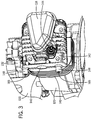
- a muffler 128 is attached to a side of the engine 110.
- the muffler 128 reduces noise emissions from combustion processes occurring within the engine 110.
- the muffler 128 includes a housing 136 having a generally rectangular body formed from two shells crimped together. In other embodiments, the body may be generally circular, square, octagonal, or other shapes.
- the housing 136 includes mounting apertures 156, with the muffler 128 fastened to the cylinder head 142 with fasteners 134 extending through the mounting apertures 156.
- In the center of the muffler 128 are a series of perforations 160 on the housing 136. Exhaust gases exit the muffler 128 through the perforations 160.
- the perforations 160 of the outlet are not in the center of the muffler housing.
- the muffler outlet includes a tube through which exhaust gases exit. Muffler geometries and dimensions vary depending upon the particular frequency and amplitude of sound to be dissipated and other factors, such as an intended application.
- the engine 110 is a four-stroke engine.
- An exhaust conduit 150 extends within the cylinder head 142. In other embodiments the exhaust conduit extends within the cylinder block 140. The exhaust gases exit the cylinder head 142 through the exhaust port 146, and into the muffler 128.
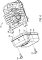
- FIG. 4 shows an exploded view of the cylinder head 142 and the muffler 128, with fasteners 134 (e.g., screws, bolts, etc.) for attaching the muffler 128 to the cylinder head 142.
- fasteners 134 e.g., screws, bolts, etc.
- FIGS. 2 and 4 show that the fasteners 134 pass through the apertures 156 in a flat portion 152 along an edge 154 of the muffler housing 136.
- Use of the flat portion 152 along the edge 154 reduces the surface area of the interface between the fasteners 134 and the muffler 128, further reducing heat transfer to the fasteners 134.
- the exhaust conduit 150 is shown extending within the cylinder head 142 to the intake pipe 168 of the muffler 128.
- the exhaust conduit 150 is chamfered proximate to where the exhaust conduit 150 contacts the intake pipe 168 of the muffler 128.
- Exhaust gases entering the muffler 128 enter a first resonance chamber 172.
- One side of the chamber 172 is formed from a separator 174 (or baffle) within the muffler 128.
- the separator includes a dome-like structure 176.
- the other sides of the chamber 172 are formed from the housing 136. Exhaust gases pass from the first chamber 172 through a series of perforations in the separator 174, into a second chamber 178. As shown in FIGS.
- Engine noise is dissipated in the first chamber 172, and further dissipated in the second chamber 178.
- Other embodiments include mufflers with different numbers of chambers and separators.
- a spark arrester may be coupled to the end of the tube.
- the intake pipe 168 of the muffler is tapered.
- the cross-sectional area of the intake pipe 168 decreases with distance away from the muffler 128.
- the rate of decrease is linear, while in other embodiments, the rate of decrease is non-linear and not continuous.
- the intake pipe 168 is inserted into the exhaust port 146, such that the end of the intake pipe 168 contacts chamfered walls of the exhaust conduit 150.
- the intake pipe 168 When the engine 110 is running, heat transfers from hot exhaust gases passing through the exhaust conduit 150 and into engine components, such as the intake pipe 168 of the muffler 128.
- the engine components expand, with different materials expanding at different rates and to different extents.
- the intake pipe 168 is designed so that thermal expansion of the materials will improve the seal between the intake pipe 168 and the exhaust conduit 150.
- FIGS. 7A , 7B, and 7C show a muffler 210 according to another exemplary embodiment.
- the muffler 210 is formed from a front shell 212 and a back shell 214 crimped together around edges 216.
- the front shell 212 includes an intake pipe 218 extending outward from the front shell 212.
- the angle of taper ⁇ ' of the intake pipe 218 is less than a chamfer angle ⁇ " of the exhaust conduit 224.
- the difference of relative angles ⁇ ', ⁇ " is approximately between two to twenty degrees, preferably between five to ten degrees, such as about seven degrees. A meeting of two angled surfaces is intended to increase the surface area of the contact 226, producing a better seal.
- FIG. 8A shows a fitting arrangement 310, with an intake 312 of a muffler and an exhaust port 314 of an engine.
- the intake 312 includes an intake pipe 318 having a uniform cross-section.
- the exhaust port 314 is formed at the end of an exhaust conduit 320.
- the exhaust conduit 320 has a chamfered portion 322 with a widening cross-sectional area leading to the exhaust port 314.
- the intake pipe 318 may be inserted into the chamfered portion 322, where an end of the intake pipe 318 contacts walls of the exhaust conduit 320. As the intake pipe 318 is inserted, some of the insertion force compresses an interface between the intake pipe 318 and the chamfered portion 322, producing an airtight seal.
- FIG. 8B shows a fitting arrangement 510, with an intake 512 of a muffler and an exhaust port 514 of an engine.
- the intake 512 includes an intake pipe 516 having a rounded end 518 with a cross-sectional area narrowing away from the muffler. In some embodiments, the rate of narrowing is not constant.
- the exhaust port 514 is formed at the end of an exhaust conduit 520.
- the exhaust conduit 520 has a cross-sectional area that widens away from the engine. In some embodiments, the rate of widening is not constant.
- the exhaust conduit 520 further includes a step 522 that serves has a backstop to limit a distance of insertion of the intake pipe 516 into the exhaust conduit 520.
Landscapes
- Engineering & Computer Science (AREA)
- Chemical & Material Sciences (AREA)
- Combustion & Propulsion (AREA)
- Mechanical Engineering (AREA)
- General Engineering & Computer Science (AREA)
- Exhaust Silencers (AREA)
Claims (14)
- Ein Motor (110), der Folgendes aufweist:ein Auspuffrohr (150), das einen Auspuffanschluss (146) an einem Ende davon aufweist, wobei das Auspuffrohr eine winkelförmige Innenfläche mit einem Querschnitt hat, der sich zum Auspuffanaschluss weitet; undeinen Schalldämpfer (128), der ein Gehäuse (136) mit einem Zuführungsrohr (168) aufweist, wobei das Zuführungsrohr durch den Auspuffanschluss eingesetzt wird, so dass das Zuführungsrohr in die winkelförmige Innenfläche des Auspuffrohrs eingekeilt wird.
- Der Motor (110) gemäß Anspruch 1, der darüberhinaus eine Befestigungsschraube (134) und einen Ansatz (148) aufweist, die Befestigungsschraube verläuft dabei durch eine Montageöffnung (156) im Gehäuse des Schalldämpfers in den Ansatz hinein, wodurch der Schalldämpfer am Motor befestigt wird.
- Der Motor (110) gemäß Anspruch 2, wobei der Ansatz (148) in einem Abstand von mehr als einem Zoll vom Auspuffanschluss liegt.
- Der Motor (110) gemäß Anspruch 2 oder Anspruch 3, der darüberhinaus ein Schalldämpferschutzgitter (162) aufweist, das Schalldämpferschutzgitter ist dabei mit der Befestigungsschraube am Ansatz angebracht.
- Der Motor (110) gemäß eines der Ansprüche 2 bis 4, wobei sich die Montageöffnung (156) im Gehäuse an einer seiner Seiten befindet, und die Befestigungsschraube (134) nicht direkt durch eine Kammer des Schalldämpfers hindurchläuft.
- Der Motor (110) eines der vorhergehenden Ansprüche, wobei das Zuführungsrohr (168) des Schalldämpfers konisch zuläuft und einen Querschnitt hat, der vom Schalldämpfer weg kleiner wird.
- Der Motor (110) eines der vorhergehenden Ansprüche, wobei das Auspuffrohr (150) eine Sperre einschließt, die die Einschiebetiefe des Zuführungsrohrs (168) in den Auspuffanschluss (146) begrenzt.
- Der Motor (110) eines der vorhergehenden Ansprüche, wobei der Schalldämpfer einen flexiblen Teil (220) des Gehäuses aufweist, wobei, bei der Befestigung am Motor, die Kompressionskraft, über eine elastische Durchbiegung des flexiblen Teils erreicht wird.
- Der Motor (110) gemäß Anspruch 8, wobei sich der flexible Teil (220) des Gehäuses (136) als Reaktion auf eine Kompression des Zuführungsrohrs durchbiegen kann, wenn es in den Auspuffanschluss eingesetzt wird, und einen luftdichten Abschluss über dem Auspuffanschluss bildet.
- Der Motor (110) gemäß eines der Ansprüche 7 bis 9, wobei die Sperre ein ringförmiger Abschnitt ist, der um die Innenfläche des Auspuffanschlusses verläuft, und wobei das Auspuffrohr darüberhinaus eine Schrägkante am Auspuffanschluss einschließt.
- Der Motor (110) gemäß Anspruch 10, wobei das Zuführungsrohr (168) einen ersten Abschrägungswinkel aufweist, die winkelförmige Fläche des Auspuffanschlusses (146), zwischen dem ringförmigen Abschnitt und der Schrägkante, hat einen zweiten Abschrägungswinkel, wobei der zweite Abschrägungswinkel größer ist als der erste Abschrägungswinkel.
- Der Motor (110) eines der vorhergehenden Ansprüche, wobei das Gehäuse (136) darüberhinaus einen Auslass aufweist.
- Der Motor (110) eines der vorhergehenden Ansprüche, wobei das Zuführungsrohr (168) fest in das Gehäuse eingebaut ist.
- Der Motor (110) gemäß eines der Ansprüche 2 bis 13, wobei die Befestigungsschraube eine Gewindeschraube (134) ist, die durch die Montageöffnung (156) durch eine Montageöse (170) im Schalldämpferschutzgitter verläuft, und in den Ansatz (148) hinein, wobei der Ansatz von einem Zylinderblock des Motors ausgeht.
Applications Claiming Priority (2)
| Application Number | Priority Date | Filing Date | Title |
|---|---|---|---|
| US12/508,424 US8251173B2 (en) | 2009-07-23 | 2009-07-23 | Muffler attachment system |
| PCT/US2010/042133 WO2011011260A1 (en) | 2009-07-23 | 2010-07-15 | Muffler attachment system |
Publications (2)
| Publication Number | Publication Date |
|---|---|
| EP2456964A1 EP2456964A1 (de) | 2012-05-30 |
| EP2456964B1 true EP2456964B1 (de) | 2016-08-17 |
Family
ID=42646362
Family Applications (1)
| Application Number | Title | Priority Date | Filing Date |
|---|---|---|---|
| EP10737163.5A Active EP2456964B1 (de) | 2009-07-23 | 2010-07-15 | Schalldämpferbefestigungssystem |
Country Status (5)
| Country | Link |
|---|---|
| US (2) | US8251173B2 (de) |
| EP (1) | EP2456964B1 (de) |
| CN (2) | CN103953428B (de) |
| AU (1) | AU2010274133B2 (de) |
| WO (1) | WO2011011260A1 (de) |
Families Citing this family (16)
| Publication number | Priority date | Publication date | Assignee | Title |
|---|---|---|---|---|
| DE102010019959A1 (de) * | 2010-05-08 | 2011-11-10 | J. Eberspächer GmbH & Co. KG | Schalldämpfer |
| JP5624850B2 (ja) * | 2010-10-29 | 2014-11-12 | 株式会社マキタ | エンジン |
| DE202011000529U1 (de) * | 2011-03-09 | 2012-06-12 | Makita Corporation | Anordnung eines Schalldämpfers an einem Verbrennungsmotor mit verbesserter Ankopplung an den Zylinder |
| USD694689S1 (en) * | 2012-04-13 | 2013-12-03 | General Electric Company | Muffler |
| USD720670S1 (en) | 2013-09-05 | 2015-01-06 | General Electric Company | Muffler |
| USD745840S1 (en) * | 2014-06-09 | 2015-12-22 | General Electric Company | Muffler |
| US20190032531A1 (en) * | 2016-01-30 | 2019-01-31 | Koki Holdings Co., Ltd. | Engine and engine work machine |
| JP2017198112A (ja) * | 2016-04-26 | 2017-11-02 | 株式会社マキタ | エンジン用マフラ |
| CN114135365A (zh) * | 2021-12-31 | 2022-03-04 | 长沙灵动航空科技有限公司 | 一种用于发电系统的消音装置 |
| USD1085012S1 (en) | 2023-10-11 | 2025-07-22 | Northern Tool & Equipment Company, Inc. | Generator assembly |
| USD1085006S1 (en) | 2023-10-11 | 2025-07-22 | Northern Tool & Equipment Company, Inc. | Generator assembly |
| USD1085009S1 (en) | 2023-10-11 | 2025-07-22 | Northern Tool & Equipment Company, Inc. | Generator assembly |
| USD1085008S1 (en) | 2023-10-11 | 2025-07-22 | Northern Tool & Equipment Company, Inc. | Generator assembly |
| USD1085010S1 (en) | 2023-10-11 | 2025-07-22 | Northern Tool & Equipment Company, Inc. | Generator assembly |
| USD1085011S1 (en) | 2023-10-11 | 2025-07-22 | Northern Tool & Equipment Company, Inc. | Generator assembly |
| USD1085007S1 (en) | 2023-10-11 | 2025-07-22 | Northern Tool & Equipment Company, Inc. | Generator assembly |
Family Cites Families (46)
| Publication number | Priority date | Publication date | Assignee | Title |
|---|---|---|---|---|
| US3106985A (en) * | 1960-12-05 | 1963-10-15 | Kenneth J Recupito | Muffler apparatus |
| US3378099A (en) * | 1967-09-15 | 1968-04-16 | Briggs & Stratton Corp | Muffler and outlet tube for small internal combustion engines |
| AU446195B2 (en) | 1970-05-12 | 1974-02-27 | Victa Limited | Improvements in mufflers for internal combustion engines |
| US3863734A (en) | 1972-10-25 | 1975-02-04 | Tecumseh Products Co | Muffler for internal combustion engines |
| US3945354A (en) | 1973-08-09 | 1976-03-23 | Textron Inc. | Exhaust port of two cycle engine |
| BR7503284A (pt) | 1974-05-28 | 1976-04-27 | Hinderks M V | Dispositivos aperfeicoados para tratamento dos gases de motores de combustao interna e veiculos e motor que utilizam os ditos dispositivos e material filamentar para os mesmos |
| US4182121A (en) * | 1976-10-26 | 1980-01-08 | Chrysler Corporation | Exhaust tuning for transverse automobile engine |
| AU517657B2 (en) | 1976-10-26 | 1981-08-20 | Chrysler Corporation | Articulated exhaust system |
| US4209177A (en) * | 1979-01-15 | 1980-06-24 | Chrysler Corporation | Exhaust seal ring |
| US4286675A (en) | 1979-06-25 | 1981-09-01 | Beaird-Poulan Division Of Emerson Electric Co. | Narrow profile power handle for line trimmer and the like |
| US4252092A (en) | 1979-09-04 | 1981-02-24 | Tecumseh Products Company | Compression release mechanism |
| US4306522A (en) | 1980-06-19 | 1981-12-22 | Briggs & Stratton Corporation | Transfer port duct for two-stroke engines |
| JPS6012885Y2 (ja) | 1980-12-25 | 1985-04-25 | 株式会社共立 | 複シリンダエンジン用排気マフラ |
| USRE33050E (en) | 1985-12-03 | 1989-09-12 | White Consolidated Industries, Inc. | Hand held gas engine blower |
| US4682571A (en) | 1985-12-17 | 1987-07-28 | Tecumseh Products Company | Exhaust gas recirculation system for crankcase scavenged two cycle engine |
| DE3729477C3 (de) * | 1987-09-03 | 1999-09-09 | Stihl Maschf Andreas | Abgasschalldämpfer für Zweitaktmotoren, insbesondere für tragbare Arbeitsgeräte wie Motorkettensägen |
| JPH01262321A (ja) | 1988-04-13 | 1989-10-19 | Suzuki Motor Co Ltd | 二サイクルエンジンの排気ディフューザー |
| DE3916872C1 (de) * | 1989-05-24 | 1990-11-15 | Friedrich Boysen Gmbh & Co Kg, 7272 Altensteig, De | |
| US5139107A (en) * | 1990-12-11 | 1992-08-18 | Kioritz Corporation | Exhaust muffler for internal combustion engines |
| US5211013A (en) * | 1991-09-17 | 1993-05-18 | Tecumseh Products Company | Muffler heat shield and method of attachment |
| JPH07310554A (ja) | 1993-03-31 | 1995-11-28 | Mitsubishi Heavy Ind Ltd | クランクケース圧縮式2サイクルエンジン |
| JPH06317150A (ja) | 1993-05-07 | 1994-11-15 | Kubota Corp | エンジンのリバース式強制空冷装置のマフラ冷却装置 |
| US5383427A (en) | 1993-07-19 | 1995-01-24 | Wci Outdoor Products, Inc. | Two-cycle, air-cooled uniflow gasoline engine for powering a portable tool |
| US5521339A (en) * | 1994-11-18 | 1996-05-28 | Wci Outdoor Products, Inc. | Catalyst muffler system |
| JP3280209B2 (ja) * | 1995-10-20 | 2002-04-30 | 株式会社共立 | 内燃機関のマフラー構造 |
| ID27315A (id) | 1998-05-04 | 2001-03-22 | Cuyuna Engine Company Inc | Mesin multi-bahan bakar |
| US6298811B1 (en) | 1998-09-29 | 2001-10-09 | Komatsu Zenoah Co. | Stratified scavenging two-cycle engine |
| SE513446C2 (sv) | 1999-01-19 | 2000-09-11 | Electrolux Ab | Vevhusspolad förbränningsmotor av tvåtaktstyp |
| JP3077693B1 (ja) * | 1999-04-12 | 2000-08-14 | 国産部品工業株式会社 | 管継手 |
| US6832664B2 (en) * | 2000-05-19 | 2004-12-21 | Siemens Vdo Automotive Inc. | Clampless hose retainer mechanism |
| KR100507168B1 (ko) * | 2002-10-31 | 2005-08-11 | 현대자동차주식회사 | 자동차 소음기 고정기구 |
| US7195094B2 (en) | 2003-02-03 | 2007-03-27 | Briggs & Stratton Corporation | Vibration reduction apparatus |
| DE10304326A1 (de) * | 2003-02-04 | 2004-08-12 | Andreas Stihl Ag & Co. Kg | Schalldämpferanordnung |
| US6975216B2 (en) | 2003-06-04 | 2005-12-13 | Briggs & Stratton Corporation | System and method for indicating fluid condition |
| US6952056B2 (en) | 2003-08-06 | 2005-10-04 | Briggs & Stratton Power Products Group, Llc | Generator including vertically shafted engine |
| JP4367918B2 (ja) * | 2004-01-09 | 2009-11-18 | 本田技研工業株式会社 | 小型エンジンの排気装置 |
| US7134418B2 (en) | 2004-06-21 | 2006-11-14 | Briggs & Stratton Corporation | Four-stroke internal combustion engine |
| US7146806B2 (en) | 2004-07-07 | 2006-12-12 | Homelite Technologies, Ltd. | Internal combustion engine cylinder and muffler assembly with catalytic converter |
| JP3955291B2 (ja) | 2004-07-13 | 2007-08-08 | 株式会社共立 | 内燃エンジンの触媒付きマフラー |
| JP3955293B2 (ja) * | 2004-08-06 | 2007-08-08 | 株式会社共立 | 内燃エンジンの触媒付きマフラー |
| US7314397B2 (en) | 2005-05-13 | 2008-01-01 | Briggs & Stratton Corporation | Standby generator |
| JP4489645B2 (ja) * | 2005-06-23 | 2010-06-23 | 本田技研工業株式会社 | 汎用エンジンのマフラ |
| MY148994A (en) * | 2005-06-23 | 2013-06-28 | Honda Motor Co Ltd | Muffler unit for general-purpose engine |
| JP4814657B2 (ja) | 2006-03-07 | 2011-11-16 | ハスクバーナ・ゼノア株式会社 | 2サイクルエンジン |
| DE102006037201A1 (de) * | 2006-08-09 | 2008-02-14 | Andreas Stihl Ag & Co. Kg | Handgeführtes Arbeitsgerät |
| US7492050B2 (en) | 2006-10-24 | 2009-02-17 | Briggs & Stratton Corporation | Cooling system for a portable generator |
-
2009
- 2009-07-23 US US12/508,424 patent/US8251173B2/en active Active
-
2010
- 2010-07-15 CN CN201410143965.6A patent/CN103953428B/zh not_active Expired - Fee Related
- 2010-07-15 CN CN201080031644.7A patent/CN102472145B/zh not_active Expired - Fee Related
- 2010-07-15 EP EP10737163.5A patent/EP2456964B1/de active Active
- 2010-07-15 WO PCT/US2010/042133 patent/WO2011011260A1/en not_active Ceased
- 2010-07-15 AU AU2010274133A patent/AU2010274133B2/en not_active Ceased
-
2012
- 2012-07-16 US US13/550,038 patent/US8413760B2/en active Active
Also Published As
| Publication number | Publication date |
|---|---|
| CN103953428B (zh) | 2017-12-26 |
| US20110017336A1 (en) | 2011-01-27 |
| CN102472145A (zh) | 2012-05-23 |
| US20120279199A1 (en) | 2012-11-08 |
| EP2456964A1 (de) | 2012-05-30 |
| CN102472145B (zh) | 2014-05-14 |
| CN103953428A (zh) | 2014-07-30 |
| AU2010274133A1 (en) | 2012-02-02 |
| US8413760B2 (en) | 2013-04-09 |
| AU2010274133B2 (en) | 2016-07-07 |
| US8251173B2 (en) | 2012-08-28 |
| WO2011011260A1 (en) | 2011-01-27 |
Similar Documents
| Publication | Publication Date | Title |
|---|---|---|
| US8251173B2 (en) | Muffler attachment system | |
| JP5581196B2 (ja) | エンジンの冷却装置 | |
| EP2479390B1 (de) | Auspufftopf für mehrzweckmotor | |
| US8424498B2 (en) | Engine blower scroll | |
| CA2080216C (en) | External spark arrestor | |
| CA2889282C (en) | An air flow guide for an internal combustion engine | |
| EP2456965B1 (de) | Zylinderkopfhaube | |
| US9605572B2 (en) | Muffler and engine system | |
| US7896127B2 (en) | Muffler unit for general-purpose engine | |
| JP4455423B2 (ja) | 汎用エンジンのマフラ構造 | |
| JPWO2017130660A1 (ja) | エンジン及びエンジン作業機 | |
| JPH09158743A (ja) | ターボチャージャー付排気管の遮熱装置 | |
| NZ215687A (en) | An exhaust manifold: baffle deflects incoming hot exhaust away from manifolds housing | |
| US7549413B1 (en) | Flame protection gasket | |
| WO2006019286A1 (en) | Front muffler | |
| JP4078035B2 (ja) | 汎用エンジン用マフラ | |
| JP2007002713A (ja) | 汎用エンジンのマフラカバー構造 | |
| JP2005299564A (ja) | 排気マニホールドガスケット | |
| KR20130050836A (ko) | 차량용 머플러의 구조 |
Legal Events
| Date | Code | Title | Description |
|---|---|---|---|
| PUAI | Public reference made under article 153(3) epc to a published international application that has entered the european phase |
Free format text: ORIGINAL CODE: 0009012 |
|
| 17P | Request for examination filed |
Effective date: 20120207 |
|
| AK | Designated contracting states |
Kind code of ref document: A1 Designated state(s): AL AT BE BG CH CY CZ DE DK EE ES FI FR GB GR HR HU IE IS IT LI LT LU LV MC MK MT NL NO PL PT RO SE SI SK SM TR |
|
| DAX | Request for extension of the european patent (deleted) | ||
| 17Q | First examination report despatched |
Effective date: 20150205 |
|
| GRAP | Despatch of communication of intention to grant a patent |
Free format text: ORIGINAL CODE: EPIDOSNIGR1 |
|
| INTG | Intention to grant announced |
Effective date: 20160216 |
|
| GRAS | Grant fee paid |
Free format text: ORIGINAL CODE: EPIDOSNIGR3 |
|
| GRAA | (expected) grant |
Free format text: ORIGINAL CODE: 0009210 |
|
| AK | Designated contracting states |
Kind code of ref document: B1 Designated state(s): AL AT BE BG CH CY CZ DE DK EE ES FI FR GB GR HR HU IE IS IT LI LT LU LV MC MK MT NL NO PL PT RO SE SI SK SM TR |
|
| REG | Reference to a national code |
Ref country code: GB Ref legal event code: FG4D |
|
| REG | Reference to a national code |
Ref country code: CH Ref legal event code: EP |
|
| REG | Reference to a national code |
Ref country code: IE Ref legal event code: FG4D |
|
| REG | Reference to a national code |
Ref country code: AT Ref legal event code: REF Ref document number: 821337 Country of ref document: AT Kind code of ref document: T Effective date: 20160915 |
|
| REG | Reference to a national code |
Ref country code: DE Ref legal event code: R096 Ref document number: 602010035610 Country of ref document: DE |
|
| REG | Reference to a national code |
Ref country code: NL Ref legal event code: MP Effective date: 20160817 |
|
| REG | Reference to a national code |
Ref country code: LT Ref legal event code: MG4D |
|
| REG | Reference to a national code |
Ref country code: AT Ref legal event code: MK05 Ref document number: 821337 Country of ref document: AT Kind code of ref document: T Effective date: 20160817 |
|
| PG25 | Lapsed in a contracting state [announced via postgrant information from national office to epo] |
Ref country code: HR Free format text: LAPSE BECAUSE OF FAILURE TO SUBMIT A TRANSLATION OF THE DESCRIPTION OR TO PAY THE FEE WITHIN THE PRESCRIBED TIME-LIMIT Effective date: 20160817 Ref country code: NL Free format text: LAPSE BECAUSE OF FAILURE TO SUBMIT A TRANSLATION OF THE DESCRIPTION OR TO PAY THE FEE WITHIN THE PRESCRIBED TIME-LIMIT Effective date: 20160817 Ref country code: NO Free format text: LAPSE BECAUSE OF FAILURE TO SUBMIT A TRANSLATION OF THE DESCRIPTION OR TO PAY THE FEE WITHIN THE PRESCRIBED TIME-LIMIT Effective date: 20161117 Ref country code: FI Free format text: LAPSE BECAUSE OF FAILURE TO SUBMIT A TRANSLATION OF THE DESCRIPTION OR TO PAY THE FEE WITHIN THE PRESCRIBED TIME-LIMIT Effective date: 20160817 Ref country code: LT Free format text: LAPSE BECAUSE OF FAILURE TO SUBMIT A TRANSLATION OF THE DESCRIPTION OR TO PAY THE FEE WITHIN THE PRESCRIBED TIME-LIMIT Effective date: 20160817 |
|
| PG25 | Lapsed in a contracting state [announced via postgrant information from national office to epo] |
Ref country code: ES Free format text: LAPSE BECAUSE OF FAILURE TO SUBMIT A TRANSLATION OF THE DESCRIPTION OR TO PAY THE FEE WITHIN THE PRESCRIBED TIME-LIMIT Effective date: 20160817 Ref country code: AT Free format text: LAPSE BECAUSE OF FAILURE TO SUBMIT A TRANSLATION OF THE DESCRIPTION OR TO PAY THE FEE WITHIN THE PRESCRIBED TIME-LIMIT Effective date: 20160817 Ref country code: PL Free format text: LAPSE BECAUSE OF FAILURE TO SUBMIT A TRANSLATION OF THE DESCRIPTION OR TO PAY THE FEE WITHIN THE PRESCRIBED TIME-LIMIT Effective date: 20160817 Ref country code: LV Free format text: LAPSE BECAUSE OF FAILURE TO SUBMIT A TRANSLATION OF THE DESCRIPTION OR TO PAY THE FEE WITHIN THE PRESCRIBED TIME-LIMIT Effective date: 20160817 Ref country code: GR Free format text: LAPSE BECAUSE OF FAILURE TO SUBMIT A TRANSLATION OF THE DESCRIPTION OR TO PAY THE FEE WITHIN THE PRESCRIBED TIME-LIMIT Effective date: 20161118 Ref country code: SE Free format text: LAPSE BECAUSE OF FAILURE TO SUBMIT A TRANSLATION OF THE DESCRIPTION OR TO PAY THE FEE WITHIN THE PRESCRIBED TIME-LIMIT Effective date: 20160817 Ref country code: PT Free format text: LAPSE BECAUSE OF FAILURE TO SUBMIT A TRANSLATION OF THE DESCRIPTION OR TO PAY THE FEE WITHIN THE PRESCRIBED TIME-LIMIT Effective date: 20161219 |
|
| PG25 | Lapsed in a contracting state [announced via postgrant information from national office to epo] |
Ref country code: EE Free format text: LAPSE BECAUSE OF FAILURE TO SUBMIT A TRANSLATION OF THE DESCRIPTION OR TO PAY THE FEE WITHIN THE PRESCRIBED TIME-LIMIT Effective date: 20160817 Ref country code: RO Free format text: LAPSE BECAUSE OF FAILURE TO SUBMIT A TRANSLATION OF THE DESCRIPTION OR TO PAY THE FEE WITHIN THE PRESCRIBED TIME-LIMIT Effective date: 20160817 |
|
| REG | Reference to a national code |
Ref country code: DE Ref legal event code: R097 Ref document number: 602010035610 Country of ref document: DE |
|
| PG25 | Lapsed in a contracting state [announced via postgrant information from national office to epo] |
Ref country code: SK Free format text: LAPSE BECAUSE OF FAILURE TO SUBMIT A TRANSLATION OF THE DESCRIPTION OR TO PAY THE FEE WITHIN THE PRESCRIBED TIME-LIMIT Effective date: 20160817 Ref country code: DK Free format text: LAPSE BECAUSE OF FAILURE TO SUBMIT A TRANSLATION OF THE DESCRIPTION OR TO PAY THE FEE WITHIN THE PRESCRIBED TIME-LIMIT Effective date: 20160817 Ref country code: SM Free format text: LAPSE BECAUSE OF FAILURE TO SUBMIT A TRANSLATION OF THE DESCRIPTION OR TO PAY THE FEE WITHIN THE PRESCRIBED TIME-LIMIT Effective date: 20160817 Ref country code: BG Free format text: LAPSE BECAUSE OF FAILURE TO SUBMIT A TRANSLATION OF THE DESCRIPTION OR TO PAY THE FEE WITHIN THE PRESCRIBED TIME-LIMIT Effective date: 20161117 Ref country code: BE Free format text: LAPSE BECAUSE OF FAILURE TO SUBMIT A TRANSLATION OF THE DESCRIPTION OR TO PAY THE FEE WITHIN THE PRESCRIBED TIME-LIMIT Effective date: 20160817 Ref country code: CZ Free format text: LAPSE BECAUSE OF FAILURE TO SUBMIT A TRANSLATION OF THE DESCRIPTION OR TO PAY THE FEE WITHIN THE PRESCRIBED TIME-LIMIT Effective date: 20160817 |
|
| REG | Reference to a national code |
Ref country code: FR Ref legal event code: PLFP Year of fee payment: 8 |
|
| PLBE | No opposition filed within time limit |
Free format text: ORIGINAL CODE: 0009261 |
|
| STAA | Information on the status of an ep patent application or granted ep patent |
Free format text: STATUS: NO OPPOSITION FILED WITHIN TIME LIMIT |
|
| 26N | No opposition filed |
Effective date: 20170518 |
|
| PG25 | Lapsed in a contracting state [announced via postgrant information from national office to epo] |
Ref country code: SI Free format text: LAPSE BECAUSE OF FAILURE TO SUBMIT A TRANSLATION OF THE DESCRIPTION OR TO PAY THE FEE WITHIN THE PRESCRIBED TIME-LIMIT Effective date: 20160817 |
|
| REG | Reference to a national code |
Ref country code: CH Ref legal event code: PL |
|
| REG | Reference to a national code |
Ref country code: IE Ref legal event code: MM4A |
|
| PG25 | Lapsed in a contracting state [announced via postgrant information from national office to epo] |
Ref country code: IE Free format text: LAPSE BECAUSE OF NON-PAYMENT OF DUE FEES Effective date: 20170715 Ref country code: LI Free format text: LAPSE BECAUSE OF NON-PAYMENT OF DUE FEES Effective date: 20170731 Ref country code: CH Free format text: LAPSE BECAUSE OF NON-PAYMENT OF DUE FEES Effective date: 20170731 |
|
| REG | Reference to a national code |
Ref country code: FR Ref legal event code: PLFP Year of fee payment: 9 |
|
| PG25 | Lapsed in a contracting state [announced via postgrant information from national office to epo] |
Ref country code: LU Free format text: LAPSE BECAUSE OF NON-PAYMENT OF DUE FEES Effective date: 20170715 |
|
| PG25 | Lapsed in a contracting state [announced via postgrant information from national office to epo] |
Ref country code: MT Free format text: LAPSE BECAUSE OF NON-PAYMENT OF DUE FEES Effective date: 20170715 |
|
| PG25 | Lapsed in a contracting state [announced via postgrant information from national office to epo] |
Ref country code: AL Free format text: LAPSE BECAUSE OF FAILURE TO SUBMIT A TRANSLATION OF THE DESCRIPTION OR TO PAY THE FEE WITHIN THE PRESCRIBED TIME-LIMIT Effective date: 20160817 |
|
| PGFP | Annual fee paid to national office [announced via postgrant information from national office to epo] |
Ref country code: IT Payment date: 20180713 Year of fee payment: 9 |
|
| PGFP | Annual fee paid to national office [announced via postgrant information from national office to epo] |
Ref country code: GB Payment date: 20180711 Year of fee payment: 9 |
|
| PG25 | Lapsed in a contracting state [announced via postgrant information from national office to epo] |
Ref country code: MC Free format text: LAPSE BECAUSE OF FAILURE TO SUBMIT A TRANSLATION OF THE DESCRIPTION OR TO PAY THE FEE WITHIN THE PRESCRIBED TIME-LIMIT Effective date: 20160817 Ref country code: HU Free format text: LAPSE BECAUSE OF FAILURE TO SUBMIT A TRANSLATION OF THE DESCRIPTION OR TO PAY THE FEE WITHIN THE PRESCRIBED TIME-LIMIT; INVALID AB INITIO Effective date: 20100715 |
|
| PG25 | Lapsed in a contracting state [announced via postgrant information from national office to epo] |
Ref country code: CY Free format text: LAPSE BECAUSE OF NON-PAYMENT OF DUE FEES Effective date: 20160817 |
|
| PG25 | Lapsed in a contracting state [announced via postgrant information from national office to epo] |
Ref country code: MK Free format text: LAPSE BECAUSE OF FAILURE TO SUBMIT A TRANSLATION OF THE DESCRIPTION OR TO PAY THE FEE WITHIN THE PRESCRIBED TIME-LIMIT Effective date: 20160817 |
|
| GBPC | Gb: european patent ceased through non-payment of renewal fee |
Effective date: 20190715 |
|
| PG25 | Lapsed in a contracting state [announced via postgrant information from national office to epo] |
Ref country code: TR Free format text: LAPSE BECAUSE OF FAILURE TO SUBMIT A TRANSLATION OF THE DESCRIPTION OR TO PAY THE FEE WITHIN THE PRESCRIBED TIME-LIMIT Effective date: 20160817 |
|
| PG25 | Lapsed in a contracting state [announced via postgrant information from national office to epo] |
Ref country code: GB Free format text: LAPSE BECAUSE OF NON-PAYMENT OF DUE FEES Effective date: 20190715 |
|
| PG25 | Lapsed in a contracting state [announced via postgrant information from national office to epo] |
Ref country code: IS Free format text: LAPSE BECAUSE OF FAILURE TO SUBMIT A TRANSLATION OF THE DESCRIPTION OR TO PAY THE FEE WITHIN THE PRESCRIBED TIME-LIMIT Effective date: 20161217 |
|
| PG25 | Lapsed in a contracting state [announced via postgrant information from national office to epo] |
Ref country code: IT Free format text: LAPSE BECAUSE OF NON-PAYMENT OF DUE FEES Effective date: 20190715 |
|
| REG | Reference to a national code |
Ref country code: DE Ref legal event code: R081 Ref document number: 602010035610 Country of ref document: DE Owner name: BRIGGS & STRATTON, LLC, WAUWATOSA, US Free format text: FORMER OWNER: BRIGGS & STRATTON CORP., WAUWATOSA, WIS., US |
|
| P01 | Opt-out of the competence of the unified patent court (upc) registered |
Effective date: 20230703 |
|
| PGFP | Annual fee paid to national office [announced via postgrant information from national office to epo] |
Ref country code: DE Payment date: 20250728 Year of fee payment: 16 |
|
| PGFP | Annual fee paid to national office [announced via postgrant information from national office to epo] |
Ref country code: FR Payment date: 20250725 Year of fee payment: 16 |