EP2453286B9 - Immersionsmikroskoplinse - Google Patents
Immersionsmikroskoplinse Download PDFInfo
- Publication number
- EP2453286B9 EP2453286B9 EP11008831.7A EP11008831A EP2453286B9 EP 2453286 B9 EP2453286 B9 EP 2453286B9 EP 11008831 A EP11008831 A EP 11008831A EP 2453286 B9 EP2453286 B9 EP 2453286B9
- Authority
- EP
- European Patent Office
- Prior art keywords
- lens
- objective
- lens group
- indicates
- aberration
- Prior art date
- Legal status (The legal status is an assumption and is not a legal conclusion. Google has not performed a legal analysis and makes no representation as to the accuracy of the status listed.)
- Not-in-force
Links
- 238000007654 immersion Methods 0.000 claims description 147
- 230000004075 alteration Effects 0.000 claims description 140
- 230000014509 gene expression Effects 0.000 claims description 102
- 230000003287 optical effect Effects 0.000 claims description 46
- 230000004907 flux Effects 0.000 claims description 19
- 230000005499 meniscus Effects 0.000 description 32
- 230000005284 excitation Effects 0.000 description 27
- 201000009310 astigmatism Diseases 0.000 description 20
- 239000006059 cover glass Substances 0.000 description 16
- 206010010071 Coma Diseases 0.000 description 12
- 238000003384 imaging method Methods 0.000 description 11
- 238000000034 method Methods 0.000 description 7
- 238000010521 absorption reaction Methods 0.000 description 2
- 239000011521 glass Substances 0.000 description 2
- 239000000463 material Substances 0.000 description 2
- 101100060388 Arabidopsis thaliana CLT1 gene Proteins 0.000 description 1
- 102100035954 Choline transporter-like protein 2 Human genes 0.000 description 1
- 101000948115 Homo sapiens Choline transporter-like protein 2 Proteins 0.000 description 1
- 206010073261 Ovarian theca cell tumour Diseases 0.000 description 1
- OAICVXFJPJFONN-UHFFFAOYSA-N Phosphorus Chemical compound [P] OAICVXFJPJFONN-UHFFFAOYSA-N 0.000 description 1
- 238000005562 fading Methods 0.000 description 1
- 230000001678 irradiating effect Effects 0.000 description 1
- 231100000760 phototoxic Toxicity 0.000 description 1
- 230000001105 regulatory effect Effects 0.000 description 1
- 208000001644 thecoma Diseases 0.000 description 1
- 238000002834 transmittance Methods 0.000 description 1
- 239000002699 waste material Substances 0.000 description 1
Images


Classifications
-
- G—PHYSICS
- G02—OPTICS
- G02B—OPTICAL ELEMENTS, SYSTEMS OR APPARATUS
- G02B21/00—Microscopes
- G02B21/33—Immersion oils, or microscope systems or objectives for use with immersion fluids
Definitions
- the present invention relates to an immersion microscope objective, and more specifically to an immersion microscope objective used in multiphoton excitation.
- the multiphoton excitation is a phenomenon equivalent to the excitation caused by the intrinsic absorption wavelength by simultaneously irradiating phosphors with the light having a wavelength of a substantially integral multiple of an absorption wavelength.
- a multiphoton excitation phenomenon is a nonlinear phenomenon and caused, for example, at a probability proportional to the square of the intensity of the excitation light in case of two-photon excitation.
- the optical density of the excitation light becomes lower at the inverse square of the distance from the focal plane. Therefore, the multiphoton excitation phenomenon occurs only in the vicinity of the focal point, and fluorescence is irradiated only from the portion.
- a multiphoton excitation microscope does not require a confocal pinhole used in a normal confocal microscope.
- an excitation phenomenon occurs only on the focal plane, there is little fading of fluorescence in a sample.
- the excitation light used in the multiphoton excitation is generally infrared light having a wavelength longer than the wavelength of normally used visible light. Generally, the longer a wavelength, the harder the light scatters (Rayleigh scattering). Therefore, although a scattering sample such as a living body sample etc. is to be observed, the excitation light can reach the deep part of the sample by the excitation by infrared light. Accordingly, the deep part of a living body which has not been observed by visible light etc. can be observed by the multiphoton excitation. In addition, since the infrared light is less phototoxic than ultraviolet light or visible light, the damage to a living body sample can be successfully suppressed.
- the fluorescent observation method using the multiphoton excitation has a number of merits, it is a very effective fluorescent observation method.
- the objective is to have a large numerical aperture, and to be appropriately aberration-corrected.
- a plurality of photons are to simultaneously collide against one phosphor.
- the objective is to have a large numerical aperture, and to be appropriately aberration-corrected.
- the excitation light is infrared light, it is necessary that the aberration of the infrared light is corrected.
- the objective has a long working distance. Since a patch clamp method is often used in the multiphoton excitation microscope, it is necessary to reserve a work space between the tip of the objective and the sample. In addition, to observe the deep part of a sample, it is necessary to reserve the distance from the tip of the objective to the object surface longer than the depth of the sample when the object surface matches the focal point of the objective. Therefore, the objective is to have a long working distance.
- Japanese Laid-open Patent Publication No. 2005-189732 discloses an objective having a long working distance.
- Japanese Laid-open Patent Publication No. 2003-15046 discloses an objective having a large numerical aperture and a correction ring.
- the present invention has been developed to provide an immersion microscope objective capable of realizing high optical performance for a bright observation from the surface to the deep portion of a sample.
- Document US 5,978,147 A1 relates to an immersion microscope objective comprising a first lens group having positive refractive power, a second lens group having positive refractive power, and a third lens group.
- the objective is characterized by a numerical aperture NA of 1.3.
- Document US 2010/0265574 A1 also relates to an immersion microscope objective comprising a first lens group having a positive refractive power, a second lens group having a positive refractive power, and a third lens group, wherein the objective satisfies the condition 0.4 ⁇ NAob x d0 ⁇ 3 with NAob being a numerical aperture on the object side of the immersion microscope objective and d0 being a working distance of the immersion microscope objective.
- An aspect of the present invention provides an immersion microscope objective having the features of claim 1.
- the objective is an immersion microscope objective for observing a sample through an immersion, and includes, in order from the object side, a first lens group G1 having positive refractive power for converting the luminous flux from an object into convergent luminous flux, a second lens group G2 having the refractive power lower than that of the first lens group G1, and a third lens group G3.
- the space between the surface (surface number s1) closest to the object of the objective and the sample plane SP is filled by the immersion not illustrated in the attached drawings to realize high numerical aperture.
- the objective is configured to satisfy the following conditional expression (1) in addition to the configuration above where NA indicates the numerical aperture on the object side of the objective and d0 indicates the working distance that is a distance from the first surface of the objective to the object surface when the lens focuses on the object surface (sample plane). 3 mm ⁇ NA ⁇ d 0 ⁇ 8 mm
- the conditional expression (1) regulates the numerical aperture of the objective and the working distance. By satisfying the conditional expression (1), the deep part of the sample can be observed with sufficient resolution and bright and high contrast in the fluorescent observation method using two-photon excitation.
- the lower limit of the conditional expression (1) If the lower limit of the conditional expression (1) is not reached, the distance from the first surface of the objective to the object surface cannot be sufficiently reserved, and it is difficult to observe the inside of the sample. Otherwise, since the numerical aperture is insufficient, a desired resolution cannot be obtained, and an image of bright and high contrast cannot be acquired. On the other hand, the upper limit of the conditional expression (1) is exceeded, it is difficult to correct the aberration for realizing the bright and high contrast with sufficient resolution with the objective designed to be included in the limited total length.
- an immersion microscope objective having high optical performance for brightly observing the deep part of a sample can be provided.
- the first lens group G1 can include a cemented lens CL1 configured by a plano-convex lens (lens L1) having a plane surface facing the object side and a meniscus lens (lens L2) having a concave surface facing the object side, and at least one single lens (lens L3 and lens L4) having positive refractive power. It is preferable that the first lens group G1 includes a plurality of single lenses, and that the lens component arranged closest to the object in the first lens group is a cemented lens.
- the first lens group G1 is configured by two single lenses (lens L3, lens L4) having positive refractive power and a cemented lens CL2 on the image side of a cemented lens CL1.
- the cemented lens CL2 is a triple cemented lens including a positive lens, a negative lens, and a positive lens cemented as having positive refractive power on the whole.
- the second lens group G2 can be a movable group to be moved by a correction ring, and include a cemented lens CL3.
- the second lens group G2 can be configured to move with respect to the first lens group G1 with the movement of the third lens group G3.
- the second lens group G2 can have the refractive power lower than that of the first lens group G1, and has the refractive power lower than that of the third lens group G3 in some embodiments.
- the second lens group G2 can include a triple cemented lens (cemented lens CL3) configured by a negative lens, a positive lens, and a negative lens having a necessary refractive power on the whole.
- the third lens group G3 has a negative refractive power, and as exemplified in FIG. 1 , can include in order from the object side, a forward lens group (lens L11, lens L12, lens L13) having a concave surface (surface number s20) facing the image side as the surface closest to the image side, and a backward lens group (lens L14, lens L15) having a concave surface (surface number s21) facing the object side as the surface closest to the object side. Furthermore, the third lens group G3 can have lower refractive power than that of the first lens group G1, and have the refractive power lower than that of the second lens group G2 in some embodiments.
- the objective has a magnification of 35 or less.
- a wide field of view can be reserved.
- the excitation light is infrared light and is not subject to the influence of scattering, but the fluorescence emitted thereby is in a visible light range (or ultraviolet light range). Therefore, the fluorescence to be detected is subject to the Rayleigh scattering by a sample. Even in this case, the scattered fluorescence can be collected without waste by having a wide field of view of the objective.
- the objective has a lens group movable along the optical axis AX, that is, it has a correction ring.
- the lens group movable along the optical axis AX that is, it has a correction ring.
- the objective can be configured so that it has a correction ring not illustrated in the attached drawings.
- the second lens group included in the objective can be a movable group that is configured to move along the optical axis AX between the first lens group G1 and the third lens group G3 by operating the correction ring as exemplified in FIG. 1 .
- the second lens group G2 and the third lens group G3 can be relatively moved with respect to the first lens group G1.
- the cemented lens included in the second lens group of the objective is a triple cemented lens having negative refractive power and configured by a negative lens, a positive lens, and a negative lens.
- a lens group is configured as a cemented lens.
- an appropriate chromatic aberration is compatible with appropriate negative refractive index.
- the appropriate chromatic aberration can be compatible with the negative appropriate refractive index by having a movable group as a lens group configured by a positive lens and a plurality of negative lenses.
- the objective configured as described above includes the first lens group G1.
- the first lens group G1 has a planoconvex lens (lens L1) having the refractive index close to that of the immersion on the side closest to the object.
- the objective realizes high numerical aperture by lower aberration occurring between an immersion and a lens.
- the field curvature can also be suppressed by the meniscus lens (lens L2) correcting the Petzval sum.
- the objective can reserve a wide field of view.
- the single lens (lens L3, lens L4) having the positive refractive power included in the first lens group G1 suppress the beam height of the divergent light emitted from the meniscus lens (lens L2) while minimizing the occurrence of the high order spherical aberration and coma aberration, then the objective can have a long working distance with a high numerical aperture. That is, using on the side closest to the object the cemented lens CL1 configured by the planoconvex lens (lens L1) and the meniscus lens (lens L2) and further using the single lens (lens L3, lens L4) having the positive refractive power, the objective can reserve a long working distance while ensuring the compatibility between the wide field of view and the high numerical aperture.
- the aberration of the objective can be appropriately corrected by configuring it by the second lens group G2 or the second lens group G2 and the third lens group G3 as a movable group although the optical path length from the objective to the focal position FP changes.
- the observation plane VP located differently in the optical axis direction from the sample plane SP is observed, that is, when the positions of a sample different in the depth direction are observed, the aberration can be appropriately corrected.
- the third lens group G3 includes, in order from the object side, the forward lens group whose surface closest to the image is the concave surface facing the image side and the backward lens group whose surface closest to the object is the concave surface facing the object side. Then, the light from the second lens group G2 can be converted into parallel light and emitted by the third lens group G3 while correcting mainly the off-axis aberration. Therefore, the objective is an infinite distance correction lens.
- conditional expressions (2) through (9) in addition to conditional expression (1).
- d1 indicates the thickness of the lens component closest to the object in the objective.
- characters nd1 and nd2 respectively indicate the refractive indexes of the lenses on the object side and the image side of the cemented lens as the lens component on the side closest to the object.
- R1 and R2 respectively indicate the curvatures of the cemented surface and the image side surface of the cemented lens as the lens component on the side closest to the object.
- L indicates the total length of the objective.
- W i indicates the width in the optical axis direction of each medium between the objective and the focal position FP of the objective.
- the character n i indicates the refractive index of each medium.
- ⁇ 1 and ⁇ 2 respectively indicate the magnifications of the first lens group and the second lens group.
- the characters f and f2 respectively indicate the focal lengths of the entire objective and the second lens group.
- the conditional expression (2) regulates the relationship between the working distance and the thickness of the cemented lens closest to the object (hereafter referred to as a leading lens).
- a leading lens In the objective having a high numerical aperture, the beam height becomes higher by a longer working distance. Therefore, although it is difficult to appropriately correct the high order aberration and the field curvature, the high order aberration and the field curvature can be appropriately corrected by satisfying the conditional expression (2).
- the conditional expression (3) regulates the difference in refractive index of the lens configuring the cemented lens (leading lens) closest to the object.
- the objective having a long working distance it is necessary especially for an objective having a low magnification to be designed to have a moderate curve of the cemented surface of the leading lens so that the off-axis aberration can be appropriately corrected.
- the Petzval sum can be suppressed while maintaining the moderate curve of the surface.
- the Petzval sum cannot be sufficiently corrected. Therefore, it is difficult to correct the coma aberration and the field curvature.
- a glass material of high refractive index is used for the lens on the image side configuring the leading lens.
- the glass material of a high refractive index normally tends to occur in self-fluorescence and has low transmittance of a short wavelength, thereby hardly observing the fluorescence appropriately.
- conditional expression (4) regulates the relationship in curvature between the cemented surface of the cemented lens (leading lens) closest to the object and the surface closest to the image.
- the conditional expression (5) regulates the relationship between the curvature of the cemented surface of the cemented lens (leading lens) closest to the object and the total length of the objective.
- An objective having a long total length can increase the number of lenses, and relatively easily increases the beam height. Therefore, although the Petzval sum cannot be sufficiently corrected for the leading lens, the Petzval sum can be appropriately corrected as the entire objective.
- the entire length of the microscope objective cannot be selected without restrictions, and the optimum total length is set within a certain range.
- the conditional expression (6) regulates the maximum amount of change of the optical path length allowed between the objective and the focal position FP while maintaining the appropriate optical performance of the objective. That is, the expression regulates the difference between the longest optical path length and the shortest optical path length allowed by the objective.
- the amount of aberration occurring on the objective changes depending on the optical path length between the objective and the focal position FP. However, since the aberration can be appropriately corrected by moving the movable group (second lens group G2) by the correction ring, appropriate optical performance can be maintained.
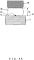
- FIGS. 2A , 2B , and 2C are explanatory views of an example of an optical path length between the immersion microscope objective and its focal position.
- the method of calculating the optical path length difference regulated by the conditional expression (6) is explained below with reference to FIGS. 2A through 2C .
- FIG. 2A is an example in which the focal position FP of the objective OB is located on the sample plane SP, that is, an example in which the observation plane VP is located on the sample plane SP.
- the medium between the objective OB and the focal position FP is only an immersion IM. Therefore, the optical path length between the objective OB and the focal position FP can be calculated as a product of the width W 1 in the optical axis direction of the immersion IM and the refractive index n 1 of the immersion IM, that is, W 1 * n 1 .
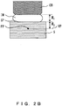
- FIG. 2B is an example in which the focal position FP of the objective OB is located in the sample plane SP, that is, an example in which the observation plane VP is located in the sample plane SP.
- the medium between the objective OB and the focal position FP is the immersion IM and the sample S.
- the optical path length between the objective OB and the focal position FP can be calculated as a sum of a product of the width W 1 in the optical axis direction of the immersion IM and the refractive index n 1 of the immersion IM and a product of the width W 2 in the optical axis direction of the sample S from the focal position FP and the refractive index n 2 of the sample S, that is, W 1 * n 1 + W 2 * n 2 .
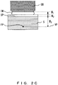
- FIG. 2C is another example in which the focal position FP of the objective OB is located in the sample plane SP.
- the media between the objective OB and the focal position FP are the immersion IM, the cover glass CG, and the sample S.
- the optical path length between the objective OB and the focal position FP can be calculated as a sum of the product of the width W 1 in the optical axis direction of the immersion IM and the refractive index n 1 of the immersion IM, the product of the width W 2 in the optical axis direction of the cover glass CG and the refractive index n 2 of the cover glass CG, and the product of the width W 3 in the optical axis direction of the sample S to the focal position FP and the refractive index n 3 of the sample S, that is, W 1 * n 1 + W 2 * n 2 + W 3 * n 3 .
- the objective OB can constantly maintain the optimum optical performance by moving the second lens group using the correction ring. Therefore, the sample S can be more appropriately observed from the surface to the deep part.
- the conditional expression (7) regulates the magnification of the first lens group G1.
- the luminous flux from the first lens group G1 becomes convergent luminous flux by satisfying the conditional expression (7).
- Even the second lens group G2 having relatively low refractive power can be improved in the amount of correction of the spherical aberration per amount of movement by the movement in the convergent luminous flux. Therefore, the amount of movement of the second lens group G2 configured as a movable group can be suppressed. As a result, a large spherical aberration can be corrected.
- the positive refractive power of the first lens group G1 is too high, and therefore it is hard to suppress the occurrence of the high order spherical aberration and the high order coma aberration in the first lens group G1.
- the upper limit of the conditional expression (7) is exceeded, the luminous flux from the first lens group G1 becomes divergent luminous flux. Therefore, it is hard to sufficiently correct the spherical aberration although the second lens group G2 is moved.
- the conditional expression (8) regulates the range of the absolute value of the magnification of the second lens group G2.
- the magnification of the movable group indicates 1 or -1 times or near offer. Therefore, although the movable group moves, the paraxial position of the image forming position hardly changes, thereby relatively easily correcting the aberration using the correction ring.
- the magnification of the movable group changes by the movement of the movable group although the magnification of the movable group is 1 or -1 times or near offer. Therefore, it is hard to suppress the fluctuation of the focal position.
- the magnification of the movable group similarly changes by the movement of the movable group although the magnification of the movable group is 1 or -1 times or near offer. Therefore, it is hard to suppress the fluctuation of the focal position.
- the conditional expression (9) regulates the relationship between the focal length of the second lens group G2 and the focal length of the entire objective.
- the focal length of the movable group (second lens group G2) is sufficiently long, thereby reducing the change of the magnification of the objective by the movement of the movable group.
- the fluctuation of the focal position caused by the amount of movement of the movable group can be suppressed.
- the magnification of the movable group changes by the movement of the movable group although the magnification of the movable group is 1 or -1 times or near offer. Therefore, it is hard to suppress the fluctuation of the focal position.
- the magnification of the movable group similarly changes by the movement of the movable group although the magnification of the movable group is 1 or -1 times or near offer. Therefore, it is hard to suppress the fluctuation of the focal position.
- conditional expressions (2) through (9) can be arbitrarily combined with the conditional expression (1).
- Each conditional expression can be limited by one of the upper limit and the lower limit.
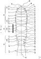
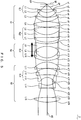
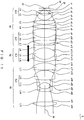
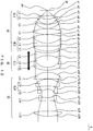
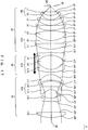
- FIG. 1 is a sectional view of the immersion microscope objective according to the present embodiment.
- FIG. 3 is a sectional view of the tube lens according to the present embodiment.
- An objective 1 exemplified in FIG. 1 is an immersion microscope objective, and includes, in order from the object side, the first lens group G1 (lens L1 through lens L7) having positive refractive power for converting the luminous flux from an object into convergent luminous flux, the second lens group G2 (lens L8 through lens L10) having negative refractive power and including cemented lens CL3, and the third lens group G3 (lens L11 through lens L15) having negative refractive power.
- the space between the objective 1 and the sample plane SP is filled with the immersion not illustrated in the attached drawings.
- the focal position FP of the objective 1 is located in the sample, and the observation plane VP is observed by the objective 1.
- the first lens group G1 is configured by, in order from the object side, the cemented lens CL1 having positive refractive power, a single lens (lens L3) as a meniscus lens having its concave surface facing the object side, a single lens (lens L4) as a double-convex lens, and a triple cemented lens (cemented lens CL2) having positive refractive power.
- the cemented lens CL1 is configured by, in order from the object side, a planoconvex lens (lens L1) having its convex surface facing the image side, and a meniscus lens (lens L2) having its concave surface facing the object side.
- the cemented lens CL2 is configured by, in order from the object side, a double-convex lens (lens L5), a planoconcave lens (lens L6) having its concave surface facing the object side, and a planoconvex lens (lens L7) having its convex surface facing the image side.
- the second lens group G2 is a movable group configured as movable along the optical axis AX between the first lens group G1 and the third lens group G3, and is a triple cemented lens (cemented lens CL3) having negative refractive power and configured by, in order from the object side, a negative lens (lens L8) as a double-concave lens, a positive lens (lens L9) as a double-convex lens, and a negative lens (lens L10) as a meniscus lens having its concave surface facing the object side.
- the refractive power of the second lens group G2 is lower than the refractive power of the first lens group G1.
- the third lens group G3 has negative refractive power on the whole and is configured by, in order from the object side, a forward lens group (lens L11, lens L12, lens L13) having negative refractive power with the surface closest to the image (surface number s20) as a concave surface facing the image side, and a backward lens group (lens L14, lens L15) having negative refractive power with the surface closest to the object (surface number s21) as a concave surface facing the object side.
- a forward lens group (lens L11, lens L12, lens L13) having negative refractive power with the surface closest to the image (surface number s20) as a concave surface facing the image side
- a backward lens group (lens L14, lens L15) having negative refractive power with the surface closest to the object (surface number s21) as a concave surface facing the object side.
- the forward lens group is configured by, in order from the object side, a meniscus lens (lens L11) having its concave surface facing the image side, and the cemented lens CL4 obtained by combining a meniscus lens (lens L12) having its concave surface facing the image side and a meniscus lens (lens L13) having its concave surface facing the image side.
- the backward lens group is configured by, in order from the object side, a planoconcave lens (lens L14) having its concave surface facing the object side and a double-convex lens (lens L15).
- a tube lens 11 exemplified in FIG. 3 is configured by, in order from the object side, a cemented lens CLT1 composed of a lens TL1 and a lens TL2 and a cemented lens CTL2 composed of a lens TL3 and a lens TL4.
- a magnification ⁇ in the second state a numerical aperture NA on the object side, a focal length f, a total length L, a working distance d0, and a thickness d1 of a lens component closest to the object are described below.
- ⁇ -24.98
- NA 1.0
- f 7.223mm
- L 73.816mm
- d0 4.036mm
- d1 6.222mm
- the focal length f1 and the magnification ⁇ 1 of the first lens group, the focal length f2 and the magnification ⁇ 2 of the second lens group, and the focal length f3 of the third lens group are described below.
- f1 9.05mm
- ⁇ 1 -5.213
- f2 -63.737mm
- ⁇ 2 4.455
- f3 -167.927mm
- the lens data of the objective 1 and the tube lens 11 is listed below.
- Objective 1 s r d nd vd 1 INF 2.5000 1.45852 67.83 2 -10.3591 3.7217 1.77250 49.60 3 -8.1150 0.2003 4 -20.7085 3.0458 1.56907 71.30 5 -11.9976 0.1998 6 35.6190 4.2045 1.56907 71.30 7 -35.6190 0.2005 8 51.8971 6.0695 1.49700 81.54 9 -15.3535 2.1000 1.67300 38.15 10 INF 3.7191 1.49700 81.54 11 -21.3761 da 12 -39.3962 2.0000 1.61340 44.27 13 14.5803 9.3164 1.43875 94.93 14 -10.9287 2.0500 1.74100 52.64 15 -21.2621 db 16 13.0526 4.8888 1.49700 81.54 17 62.3697 0.2000 18 14.3893 4.9710 1.49700 81.54 19 77.81
- s indicates a surface number
- r indicates a curvature radius (mm)
- d indicates a surface interval (mm)
- nd indicates the refractive index for the d line
- vd indicates the Abbe number for the d line.
- the surface number s1 indicates the first surface (surface closest to the object) of the objective 1
- the surface number s24 indicates the surface closest to the image of the objective 1.
- the surface number s25 indicates the first surface (surface closest to the object) of the tube lens 11
- the surface number s30 indicates the surface closest to the image of the tube lens 11.
- the interval between the objective 1 and the tube lens 11 is 116.096mm.
- the surface interval d11 between the surface number s11 and the surface number s12 and the surface interval d15 between the surface number s15 and the surface number s16 are variables da and db respectively which depend on the movement of the second lens group G2 (cemented lens CL3) in the optical axis direction.
- the variables da and db are adjusted by the correction ring to appropriately correct the spherical aberration which changes depending on the change in optical path length between the objective 1 and the focal position.
- the data above exemplifies the relationships, in order from left to right, in the case where the sample plane SP is observed, in the case where the inside of the sample (depth of 2 mm) is observed, and in the case where the inside deeper in the sample (depth of 3.9128 mm) is observed.
- S indicates a sample
- CG indicates a cover glass
- IM indicates an immersion.
- the average refractive index refers to the average refractive index for the light of 900 nm.
- the cover glass CG is used only when the inside deeper in the sample (depth of 3. 9128 mm) is observed.
- the objective 1 satisfies the conditional expressions (1) through (9) except the conditional expression (8) as expressed by the following expressions (A1) through (A9).
- the expressions (A1) through (A9) respectively correspond to the conditional expressions (1) through (9).
- the wavefront aberration is 0.012 ⁇ (that is, 1.2 % of the wavelength ⁇ ).
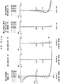
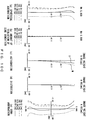
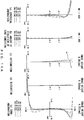
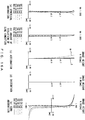
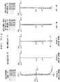
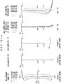
- FIGS. 4A , 4B , and 4C illustrate the aberrations when the objective 1 according to the present embodiment and the tube lens 11 are used in combination, and illustrate the aberration on the imaging plane on the image side.
- FIGS. 4A , 4B , and 4C respectively illustrates the aberration with the settings above in the case where the sample plane SP is observed, in the case where the inside of the sample (depth of 2 mm) is observed, and in the case where the inside deeper in the sample (depth of 3.9128 mm) is observed.
- FIGS. 4A , 4B , and 4C respectively illustrates the aberration with the settings above in the case where the sample plane SP is observed, in the case where the inside of the sample (depth of 2 mm) is observed, and in the case where the inside deeper in the sample (depth of 3.9128 mm) is observed.
- FIG. 4A , 4B , and 4C illustrates, in order from left to right, (a) spherical aberration, (b) amount of violation against sine condition, (c) astigmatism, (d) distortion, and (e) coma aberration.
- Each view illustrates an appropriate correction.
- "M” and "S” in the view of the astigmatism respectively indicate a meridional component and a sagittal component.
- FIG. 5 is a sectional view of the immersion microscope objective according to the present embodiment.
- An objective 2 illustrated in FIG. 5 is an immersion microscope objective, and the lens configuration is the same as that of the objective 1 according to the embodiment 1, and the detailed explanation is omitted here.
- the space between the objective 2 and the sample plane SP is filled with the immersion not illustrated in the attached drawings.
- the focal position FP of the objective 2 is located in the sample, and the observation plane VP is observed by the objective 2.
- a magnification ⁇ in the second state a numerical aperture NA on the object side, a focal length f, a total length L, a working distance d0, and a thickness d1 of a lens component closest to the object are described below.
- ⁇ -24.98
- NA 1.0
- f 7.223mm
- L 73.961mm
- d0 4.036mm
- d1 6.302mm
- the focal length f1 and the magnification ⁇ 1 of the first lens group, the focal length f2 and the magnification ⁇ 2 of the second lens group, and the focal length f3 of the third lens group are described below.
- f1 9.001mm
- ⁇ 1 -4.936
- f2 -60.587mm
- ⁇ 2 4.682
- f3 -167.236mm
- the lens data of the objective 2 is listed below.
- Objective 2 s r d nd vd 1 INF 2.5000 1.45852 67.83 2 -10.3591 3.8017 1.77250 49.60 3 -8.1150 0.2026 4 -26.6221 3.1832 1.56907 71.30 5 -12.9210 0.2000 6 34.0995 4.3097 1.56907 71.30 7 -34.0995 0.2000 8 68.0280 5.9020 1.49700 81.54 9 -14.9981 2.1000 1.67300 38.15 10 INF 3.7468 1.49700 81.54 11 -20.8746 da 12 -29.8307 2.0000 1.61340 44.27 13 14.5426 9.2598 1.43875 94.93 14 -10.9368 2.0500 1.74100 52.64 15 -19.6665 db 16 13.1254 4.8429 1.49700 81.54 17 63.3527 0.2000 18 13.9196 5.0144 1.49700 81.54 19 70.2577 2.2000 1.
- the data above exemplifies the relationships, in order from left to right, in the case where the sample plane SP is observed, in the case where the inside of the sample (depth of 2 mm) is observed, and in the case where the inside deeper in the sample (depth of 4 mm) is observed.
- S indicates a sample
- CG indicates a cover glass
- IM indicates an immersion.
- the average refractive index refers to the average refractive index for the light of 900 nm.
- the cover glass CG is used only when the inside deeper in the sample (depth of 4 mm) is observed.
- the objective 2 satisfies the conditional expressions (1) through (9) except the conditional expression (8) as expressed by the following expressions (B1) through (B9).
- the expressions (B1) through (B9) respectively correspond to the conditional expressions (1) through (9).
- the wavefront aberration is 0.009 ⁇ (that is, 0.9 % of the wavelength ⁇ ).
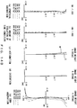
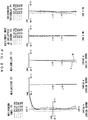
- FIGS. 6A , 6B , and 6C illustrate the aberrations when the objective 2 according to the present embodiment and the tube lens 11 exemplified in FIG. 3 are used in combination, and illustrate the aberration on the imaging plane on the image side.
- FIGS. 6A , 6B , and 6C respectively illustrates the aberration with the settings above in the case where the sample plane SP is observed, in the case where the inside of the sample (depth of 2 mm) is observed, and in the case where the inside deeper in the sample (depth of 4 mm) is observed.
- FIGS. 6A , 6B , and 6C illustrate the aberration with the settings above in the case where the sample plane SP is observed, in the case where the inside of the sample (depth of 2 mm) is observed, and in the case where the inside deeper in the sample (depth of 4 mm) is observed.
- 6A , 6B , and 6C illustrates, in order from left to right, (a) spherical aberration, (b) amount of violation against sine condition, (c) astigmatism, (d) distortion, and (e) coma aberration.
- Each view illustrates an appropriate correction.
- "M” and "S” in the view of the astigmatism respectively indicate a meridional component and a sagittal component.
- the interval between the objective 2 and the tube lens 11 is 116.09 mm.
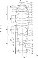
- FIG. 7 is a sectional view of the immersion microscope objective according to the present embodiment.
- An objective 3 illustrated in FIG. 7 is an immersion microscope objective, and the lens configuration is the same as that of the objective 1 according to the embodiment 1, and the detailed explanation is omitted here.
- the space between the objective 3 and the sample plane SP is filled with the immersion not illustrated in the attached drawings.
- the focal position FP of the objective 3 is located in the sample, and the observation plane VP is observed by the objective 3.
- a magnification ⁇ in the second state a numerical aperture NA on the object side, a focal length f, a total length L, a working distance d0, and a thickness d1 of a lens component closest to the object are described below.
- the focal length f1 and the magnification ⁇ 1 of the first lens group, the focal length f2 and the magnification ⁇ 2 of the second lens group, and the focal length f3 of the third lens group are described below.
- f1 9.298mm
- ⁇ 1 -4.321
- f2 -49.232mm
- ⁇ 2 6,
- f3 -187.647mm
- the lens data of the objective 3 is listed below.
- Objective 3 s r d nd vd 1 INF 2.5000 1.45852 67.83 2 -10.3591 2.5578 1.77250 49.60 3 -8.3631 0.2096 4 -75.0048 3.4190 1.56907 71.30 5 -16.6318 0.2990 6 36.0431 4.0187 1.56907 71.30 7 -36.0431 0.3197 8 76.8450 5.5288 1.49700 81.54 9 -15.4459 2.1000 1.67300 38.15 10 INF 3.4283 1.49700 81.54 11 -21.7765 da 12 -29.3326 2.0000 1.61340 44.27 13 14.7362 8.9160 1.43875 94.93 14 -10.9727 2.0500 1.74100 52.64 15 -21.2817 db 16 12.7915 4.7093 1.49700 81.54 17 57.2161 0.2000 18 12.9216 4.7594 1.49700 81.54 19 43.
- the data above exemplifies the relationships, in order from left to right, in the case where the sample plane SP is observed, in the case where the inside of the sample (depth of 3 mm) is observed, and in the case where the inside deeper in the sample (depth of 5.9241 mm) is observed.
- S indicates a sample
- CG indicates a cover glass
- IM indicates an immersion.
- the average refractive index refers to the average refractive index for the light of 900 nm.
- the cover glass CG is used only when the inside deeper in the sample (depth of 5.9241 mm) is observed.
- the objective 3 satisfies the conditional expressions (1) through (9) except the conditional expression (8) as expressed by the following expressions (C1) through (C9).
- the expressions (C1) through (C9) respectively correspond to the conditional expressions (1) through (9).
- the wavefront aberration is 0.009 ⁇ (that is, 0.9 % of the wavelength ⁇ ).
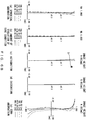
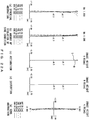
- FIGS. 8A , 8B , and 8C illustrate the aberrations when the objective 3 according to the present embodiment and the tube lens 11 exemplified in FIG. 3 are used in combination, and illustrate the aberration on the imaging plane on the image side.
- FIGS. 8A , 8B , and 8C respectively illustrates the aberration with the settings above in the case where the sample plane SP is observed, in the case where the inside of the sample (depth of 3 mm) is observed, and in the case where the inside deeper in the sample (depth of 5.9241 mm) is observed.
- FIGS. 8A , 8B , and 8C illustrate the aberration with the settings above in the case where the sample plane SP is observed, in the case where the inside of the sample (depth of 3 mm) is observed, and in the case where the inside deeper in the sample (depth of 5.9241 mm) is observed.
- 8A , 8B , and 8C illustrates, in order from left to right, (a) spherical aberration, (b) amount of violation against sine condition, (c) astigmatism, (d) distortion, and (e) coma aberration.
- Each view illustrates an appropriate correction.
- "M” and "S” in the view of the astigmatism respectively indicate a meridional component and a sagittal component.
- the interval between the objective 3 and the tube lens 11 is 115.64 mm.
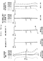
- FIG. 9 is a sectional view of the immersion microscope objective according to the present embodiment.
- An objective 4 illustrated in FIG. 9 is an immersion microscope objective, and the lens configuration is the similar as that of the objective 1 according to the embodiment 1, but is different from the objective 1 according to the embodiment 1 in the configuration of the third lens group G3. Therefore, only the configuration of the third lens group G3 different from the objective 1 according to the embodiment 1 is described below.
- the third lens group G3 has negative refractive power on the whole and is configured by, in order from the object side, a forward lens group (lens L11, lens L12, lens L13) having positive refractive power with the surface closest to the image (surface number s20) as a concave surface facing the image side, and a backward lens group (lens L14, lens L15) having negative refractive power with the surface closest to the object (surface number s21) as a concave surface facing the object side.
- a forward lens group (lens L11, lens L12, lens L13) having positive refractive power with the surface closest to the image (surface number s20) as a concave surface facing the image side
- a backward lens group (lens L14, lens L15) having negative refractive power with the surface closest to the object (surface number s21) as a concave surface facing the object side.
- the forward lens group is configured by, in order from the object side, a double-convex lens (lens L11) and the cemented lens CL4 obtained by combining a double-convex lens (lens L12) and a double-concave lens (lens L13).
- the backward lens group is configured by, in order from the object side, a planoconcave lens (lens L14) having its concave surface facing the object side and a meniscus lens (lens L15) having its concave surface facing the object side.
- the space between the objective 4 and the sample plane SP is filled with the immersion not illustrated in the attached drawings.
- the focal position FP of the objective 4 is located in the sample, and the observation plane VP is observed by the objective 4.
- a magnification ⁇ in the second state a numerical aperture NA on the object side, a focal length f, a total length L, a working distance d0, and a thickness d1 of a lens component closest to the object are described below.
- the focal length f1 and the magnification ⁇ 1 of the first lens group, the focal length f2 and the magnification ⁇ 2 of the second lens group, and the focal length f3 of the third lens group are described below.
- f1 9.939mm
- ⁇ 1 -3.479
- f2 -40.566mm
- ⁇ 2 6.197
- f3 -155.967mm
- the lens data of the objective 4 is listed below.
- Objective 4 s r d nd vd 1 INF 2.5000 1.45852 67.83 2 -11.5000 2.5000 1.77250 49.60 3 -9.5926 0.2035 4 -142.7255 3.3474 1.56907 71.30 5 -20.2047 0.2030 6 40.3202 4.0947 1.56907 71.30 7 -40.3202 0.2128 8 49.8999 5.8110 1.49700 81.54 9 -17.6397 2.1000 1.67300 38.15 10 INF 3.1467 1.49700 81.54 11 -24.7988 da 12 -33.1242 2.0000 1.61340 44.27 13 14.2451 7.9613 1.43875 94.93 14 -11.8396 2.0500 1.74100 52.64 15 -26.2603 db 16 16.4118 4.4714 1.49700 81.54 17 -68.1763 0.2000 18 13.4958 5.3730 1.49700 81.54 19 -70.7767
- the data above exemplifies the relationships, in order from left to right, in the case where the sample plane SP is observed, in the case where the inside of the sample (depth of 4 mm) is observed, and in the case where the inside deeper in the sample (depth of 7.9385 mm) is observed.
- S indicates a sample
- CG indicates a cover glass
- IM indicates an immersion.
- the average refractive index refers to the average refractive index for the light of 900 nm.
- the cover glass CG is used only when the inside deeper in the sample (depth of 7.9385 mm) is observed.
- the objective 4 according to the present embodiment satisfies the conditional expressions (1) through (9) except the conditional expression (8) as expressed by the following expressions (D1) through (C9).
- the expressions (D1) through (D9) respectively correspond to the conditional expressions (1) through (9).
- the wavefront aberration is 0.007 ⁇ (that is, 0.7 % of the wavelength ⁇ ).
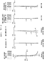
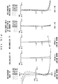
- FIGS. 10A , 10B , and 10C illustrate the aberrations when the objective 4 according to the present embodiment and the tube lens 11 exemplified in FIG. 3 are used in combination, and illustrate the aberration on the imaging plane on the image side.
- FIGS. 10A , 10B , and 10C respectively illustrates the aberration with the settings above in the case where the sample plane SP is observed, in the case where the inside of the sample (depth of 4 mm) is observed, and in the case where the inside deeper in the sample (depth of 7.9385 mm) is observed.
- FIGS. 10A , 10B , and 10C illustrate the aberration with the settings above in the case where the sample plane SP is observed, in the case where the inside of the sample (depth of 4 mm) is observed, and in the case where the inside deeper in the sample (depth of 7.9385 mm) is observed.
- 10A , 10B , and 10C illustrates, in order from left to right, (a) spherical aberration, (b) amount of violation against sine condition, (c) astigmatism, (d) distortion, and (e) coma aberration.
- Each view illustrates an appropriate correction.
- "M” and "S” in the view of the astigmatism respectively indicate a meridional component and a sagittal component.
- the interval between the objective 4 and the tube lens 11 is 115.541 mm.
- FIG. 11 is a sectional view of the immersion microscope objective according to the present embodiment.
- An objective 5 illustrated in FIG. 11 is an immersion microscope objective, and the lens configuration is the similar as that of the objective 1 according to the embodiment 1, but is different from the objective 1 according to the embodiment 1 in the configurations of the first lens group G1 and the third lens group G3. Therefore, only the configurations of first lens group G1 and the third lens group G3 different from the objective 1 according to the embodiment 1 are described below.
- the first lens group G1 is configured by, in order from the object side, the cemented lens CL1 having positive refractive power for converting the luminous flux from an object into a convergent luminous flux, a single lens (lens L3) as a double-convex lens, a single lens (lens L4) as a double-convex lens, and a triple cemented lens (cemented lens CL2) having positive refractive power.
- the cemented lens CL1 is configured by, in order from the object side, a planoconvex lens (lens L1) having its convex surface facing the image side, and a meniscus lens (lens L2) having its concave surface facing the object side.
- the cemented lens CL2 is configured by, in order from the object side, a double-convex lens (lens L5), a double-concave lens (lens L6), and a double-convex lens (lens L7).
- the third lens group G3 has positive refractive power on the whole and is configured by, in order from the object side, a forward lens group (lens L11, lens L12, lens L13) having positive refractive power with the surface closest to the image (surface number s20) as a concave surface facing the image side, and a backward lens group (lens L14, lens L15) having positive refractive power with the surface closest to the object (surface number s21) as a concave surface facing the object side.
- a forward lens group (lens L11, lens L12, lens L13) having positive refractive power with the surface closest to the image (surface number s20) as a concave surface facing the image side
- a backward lens group (lens L14, lens L15) having positive refractive power with the surface closest to the object (surface number s21) as a concave surface facing the object side.
- the forward lens group is configured by, in order from the object side, a double-convex lens (lens L11), and the cemented lens CL4 obtained by combining a double-convex lens (lens L12) and a double-concave lens (lens L13).
- the backward lens group is configured by, in order from the object side, a meniscus lens (lens L14) having its concave surface facing the object side, and a double-convex lens (lens L15).
- the space between the objective 5 and the sample plane SP is filled with the immersion not illustrated in the attached drawings.
- the focal position FP of the objective 5 is located in the sample, and the observation plane VP is observed by the objective 5.
- a magnification ⁇ in the second state a numerical aperture NA on the object side, a focal length f, a total length L, a working distance d0, and a thickness d1 of a lens component closest to the object are described below.
- ⁇ -24.98
- NA 1.0
- f 7.223mm
- L 75.860mm
- d0 4.03mm
- d1 5.630mm
- the focal length f1 and the magnification ⁇ 1 of the first lens group, the focal length f2 and the magnification ⁇ 2 of the second lens group, and the focal length f3 of the third lens group are described below.
- f1 8.621mm
- ⁇ 1 -9.637
- f2 -67.472mm
- ⁇ 2 -4.483
- f3 308.289mm
- the lens data of the objective 5 is listed below.
- Objective 5 s r d nd vd 1 INF 1.5400 1.45852 67.83 2 -7.4691 4.0897 1.77250 49.60 3 -7.3372 0.3000 4 155.1922 3.0213 1.56907 71.30 5 -26.5121 0.3000 6 54.1543 3.1138 1.56907 71.30 7 -44.3983 0.3000 8 34.3556 7.2572 1.49700 81.54 9 -17.2116 2.1000 1.67300 38.15 10 138.8923 3.2396 1.49700 81.54 11 -26.9797 da 12 -59.2926 2.0000 1.61340 44.27 13 14.0602 9.3195 1.43875 94.93 14 -12.1679 2.0000 1.74100 52.64 15 -25.1101 db 16 19.3230 5.7836 1.49700 81.54 17 -94.8819 0.1991 18 12.9797 7.9023 1.49700 81.54
- the data above exemplifies the relationships, in order from left to right, in the case where the sample plane SP is observed, in the case where the inside of the sample (depth of 2 mm) is observed, and in the case where the inside deeper in the sample (depth of 4 mm) is observed.
- S indicates a sample
- IM indicates an immersion.
- the average refractive index refers to the average refractive index for the light of 900 nm.
- the objective 5 satisfies the conditional expressions (1) through (9) except the conditional expressions (4), (5), and (8) as expressed by the following expressions (E1) through (E9).
- the expressions (E1) through (E9) respectively correspond to the conditional expressions (1) through (9).
- the wavefront aberration is 0.005 ⁇ (that is, 0.5 % of the wavelength ⁇ ).
- FIGS. 12A , 12B , and 12C illustrate the aberrations when the objective 5 according to the present embodiment and the tube lens 11 exemplified in FIG. 3 are used in combination, and illustrate the aberration on the imaging plane on the image side.
- FIGS. 12A , 12B , and 12C respectively illustrates the aberration with the settings above in the case where the sample plane SP is observed, in the case where the inside of the sample (depth of 2 mm) is observed, and in the case where the inside deeper in the sample (depth of 4 mm) is observed.
- FIGS. 12A , 12B , and 12C illustrate the aberration with the settings above in the case where the sample plane SP is observed, in the case where the inside of the sample (depth of 2 mm) is observed, and in the case where the inside deeper in the sample (depth of 4 mm) is observed.
- FIGS. 12A , 12B , and 12C illustrate the aberration with the settings above in the case where the sample plane SP is observed, in the case where the inside
- 12A , 12B , and 12C illustrates, in order from left to right, (a) spherical aberration, (b) amount of violation against sine condition, (c) astigmatism, (d) distortion, and (e) coma aberration.
- Each view illustrates an appropriate correction.
- "M” and "S” in the view of the astigmatism respectively indicate a meridional component and a sagittal component.
- the interval between the objective 5 and the tube lens 11 is 115.0 mm.
- FIG.13 is a sectional view of the immersion microscope objective according to the present embodiment.
- An objective 6 illustrated in FIG. 13 is an immersion microscope objective, and the lens configuration is the same as that of the objective 1 according to the embodiment 1, and the detailed explanation is omitted here.
- the space between the objective 6 and the sample plane SP is filled with the immersion not illustrated in the attached drawings.
- the focal position FP of the objective 6 is located on the sample plane SP, and the sample plane SP is observed by the objective 6.
- a magnification ⁇ in the second state a numerical aperture NA on the object side, a focal length f, a total length L, a working distance d0, and a thickness d1 of a lens component closest to the object are described below.
- ⁇ -24.98
- NA 1.0
- f 7.223mm
- L 73.924mm
- d0 4.03mm
- d1 6.140mm
- the focal length f1 and the magnification ⁇ 1 of the first lens group, the focal length f2 and the magnification ⁇ 2 of the second lens group, and the focal length f3 of the third lens group are described below.
- f1 8.358mm
- ⁇ 1 -4.829
- f2 -49.098mm
- ⁇ 2 9.517
- f3 -333.213mm
- the lens data of the objective 6 is listed below.
- Objective 6 s r d nd vd 1 INF 2.5000 1.45182 67.83 2 -10.3591 3.6400 1.75821 49.60 3 -8.1150 0.2037 4 -17.0022 3.0261 1.56178 71.30 5 -11.2198 0.2026 6 35.9884 4.1116 1.56178 71.30 7 -35.9884 0.2108 8 39.0754 6.3096 1.49126 81.54 9 -15.4049 2.1000 1.65754 38.15 10 INF 3.7168 1.49126 81.54 11 -20.8957 da 12 -31.0852 2.0000 1.60085 44.27 13 16.0314 8.7791 1.43436 94.93 14 -11.0434 2.0500 1.72789 52.64 15 -22.3667 db 16 13.9178 4.9330 1.49126 81.54 17 157.3673 0.2000 18 13.4583 5.1563 1.49126 81.54 19 73
- the data above exemplifies the relationships, in order from left to right, in the case where the sample plane SP is observed through the immersion having the refractive index of 1.32782, in the case where the sample plane SP is observed through the immersion having the refractive index of 1.3589, and in the case where the sample plane SP is observed through the immersion having the refractive index of 1.39728.
- IM indicates an immersion.
- the average refractive index of the immersion refers to the average refractive index for the light of 900 nm.
- the objective 6 satisfies the conditional expressions (1) through (9) except the conditional expression (8) as expressed by the following expressions (F1) through (F9).
- the expressions (F1) through (F9) respectively correspond to the conditional expressions (1) through (9).
- the wavefront aberration is 0.011 ⁇ (that is, 1.1 % of the wavelength ⁇ ).
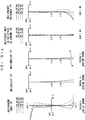
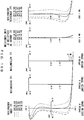
- FIGS. 14A , 14B , and 14C illustrate the aberrations when the objective 6 according to the present embodiment and the tube lens 11 exemplified in FIG. 3 are used in combination, and illustrate the aberration on the imaging plane on the image side.
- FIGS. 14A , 14B , and 14C respectively illustrates the aberration in the case where the sample plane SP is observed through the immersion having the refractive index of 1.32782, in the case where the sample plane SP is observed through the immersion having the refractive index of 1. 3589, and in the case where the sample plane SP is observed through the immersion having the refractive index of 1.39728.
- FIGS. 14A , 14B , and 14C illustrate the aberrations when the objective 6 according to the present embodiment and the tube lens 11 exemplified in FIG. 3 are used in combination, and illustrate the aberration on the imaging plane on the image side.
- FIGS. 14A , 14B , and 14C respectively illustrates the aberration in the case where the sample plane SP is observed through
- 14A , 14B , and 14C illustrates, in order from left to right, (a) spherical aberration, (b) amount of violation against sine condition, (c) astigmatism, (d) distortion, and (e) coma aberration.
- Each view illustrates an appropriate correction.
- "M” and "S” in the view of the astigmatism respectively indicate a meridional component and a sagittal component.
- the interval between the objective 6 and the tube lens 11 is 117.046 mm.
- FIG. 15 is a sectional view of the immersion microscope objective according to the present embodiment.
- An objective 7 is an immersion microscope objective, and includes, in order from the object side, the first lens group G1 (lens L1 through lens L7) having the positive refractive power for converting the luminous flux from the object into the convergent luminous flux, the second lens group G2 (lens L8 through lens L10) including the cemented lens CL3 and having the positive refractive power, and the third lens group G3 (lens L11 through lens L15) having the negative refractive power.
- the space between the objective 7 and the sample plane SP is filled with the immersion not illustrated in the attached drawings.
- the focal position FP of the objective 7 is located on the sample plane SP, and the sample plane SP is observed by the objective 7.
- the first lens group G1 is configured by, in order from the object side, the cemented lens CL1 having positive refractive power, a single lens (lens L3) as a meniscus lens having its concave surface facing the object side, a single lens (lens L4) as a meniscus lens having its concave surface facing the object side, and a triple cemented lens (cemented lens CL2) having positive refractive power.
- the cemented lens CL1 is configured by, in order from the object side, a planoconvex lens (lens L1) having its convex surface facing the image side, and a meniscus lens (lens L2) having its concave surface facing the object side.
- the cemented lens CL2 is configured by, in order from the object side, a double-convex lens (lens L5), a double-concave lens (lens L6), and a double-convex lens (lens L7).
- the second lens group G2 is a movable group configured as movable along the optical axis AX between the first lens group G1 and the third lens group G3, and is a triple cemented lens (cemented lens CL3) having positive refractive power and configured by, in order from the object side, a negative lens (lens L8) as a meniscus lens having its concave surface facing the image side, a positive lens (lens L9) as a double-convex lens, and a negative lens (lens L10) as a meniscus lens having its concave surface facing the object side.
- the refractive power of the second lens group G2 is lower than the refractive power of the first lens group G1, and is lower than the refractive power of the third lens group G3.
- the third lens group G3 has negative refractive power on the whole and is configured by, in order from the object side, a forward lens group (lens L11, lens L12, lens L13) having negative refractive power with the surface closest to the image (surface number s20) as a concave surface facing the image side, and a backward lens group (lens L14, lens L15) having negative refractive power with the surface closest to the object (surface number s21) as a concave surface facing the object side.
- a forward lens group (lens L11, lens L12, lens L13) having negative refractive power with the surface closest to the image (surface number s20) as a concave surface facing the image side
- a backward lens group (lens L14, lens L15) having negative refractive power with the surface closest to the object (surface number s21) as a concave surface facing the object side.
- the forward lens group is configured by, in order from the object side, a meniscus lens (lens L11) having its concave surface facing the image side, and the cemented lens CL4 obtained by combining a meniscus lens (lens L12) having its concave surface facing the image side and a meniscus lens (lens L13) having its concave surface facing the image side.
- the backward lens group is configured by, in order from the object side, a planoconcave lens (lens L14) having its concave surface facing the object side and a planoconvex lens (lens L15) having its convex surface facing the image side.
- a magnification ⁇ in the second state a numerical aperture NA on the object side, a focal length f, a total length L, a working distance d0, and a thickness d1 of a lens component closest to the object are described below.
- ⁇ -24.966
- the focal length f1 and the magnification ⁇ 1 of the first lens group, the focal length f2 and the magnification ⁇ 2 of the second lens group, and the focal length f3 of the third lens group are described below.
- f1 9.885mm
- ⁇ 1 -7.146
- f2 737.122mm
- ⁇ 2 0.987
- f3 -51.73mm
- the lens data of the objective 7 is listed below.
- the data above exemplifies the relationships, in order from left to right, in the case where the sample plane SP is observed through the immersion having the refractive index of 1.32666, and in the cases where the sample plane SP and inside of the sample (depth of 3.8823 mm) are observed through the immersion having the refractive index of 1.37172.
- S indicates a sample
- CG indicates a cover glass
- IM indicates an immersion.
- the average refractive index of the immersion refers to the average refractive index for the light of 900 nm.
- the objective 7 satisfies the conditional expressions (1) through (9) as expressed by the following expressions (G1) through (G9).
- the expressions (G1) through (G9) respectively correspond to the conditional expressions (1) through (9).
- R 1 / R 2 1.297
- the wavefront aberration is 0.002 ⁇ (that is, 0.2 % of the wavelength ⁇ ).
- FIGS. 16A , 16B , and 16C illustrate the aberrations when the objective 7 according to the present embodiment and the tube lens 11 illustrated in FIG. 3 are used in combination, and illustrate the aberration on the imaging plane on the image side.
- FIGS. 16A , 16B , and 16C respectively illustrates the aberration in the case where the sample plane SP is observed through the immersion having the refractive index of 1.32666, in the case where the sample plane SP is observed through the immersion having the refractive index of 1.37172, and in the case where the inside of the sample (depth of 3.8823 mm) is observed through the immersion having the refractive index of 1.37787.
- 16A , 16B , and 16C illustrates, in order from left to right, (a) spherical aberration, (b) amount of violation against sine condition, (c) astigmatism, (d) distortion, and (e) coma aberration.
- Each view illustrates an appropriate correction.
- "M” and "S” in the view of the astigmatism respectively indicate a meridional component and a sagittal component.
- the interval between the objective 7 and the tube lens 11 is 85.305 mm.
- FIG. 17 is a sectional view of the immersion microscope objective according to the present embodiment.
- An objective 8 illustrated in FIG. 17 is an immersion microscope objective, and the lens configuration is the similar as that of the objective 7 according to the embodiment 7, but is different from the objective 7 according to the embodiment 7 in the configurations of the first lens group G1 and the third lens group G3. Therefore, only the configurations of the first lens group G1 and the third lens group G3 different from the objective 7 according to the embodiment 7 are described below.
- the configuration of the second lens group G2 is similar to the configuration of the objective 7 according to the embodiment 7, but the second lens group G2 has negative refractive power unlike the objective 7 according to the embodiment 7. Furthermore, the refractive power of the second lens group G2 is lower than the refractive power of the first lens group G1, and is lower than the refractive power of the third lens group G3.
- the first lens group G1 is configured by, in order from the object side, the cemented lens CL1 having positive refractive power for converting the luminous flux from an object into a convergent luminous flux, a single lens (lens L3) as a meniscus lens having its concave surface facing the object side, a single lens (lens L4) as a meniscus lens having its concave surface facing the object side, and a triple cemented lens (cemented lens CL2) having positive refractive power.
- the cemented lens CL1 is configured by, in order from the object side, a planoconvex lens (lens L1) having its convex surface facing the image side, and a meniscus lens (lens L2) having its concave surface facing the object side.
- the cemented lens CL2 is configured by, in order from the object side, a double-convex lens (lens L5), a meniscus lens (lens L6) having its concave surface facing the object side, and a meniscus lens (lens L7) having its concave surface facing the image side.
- the third lens group G3 has negative refractive power on the whole and is configured by, in order from the object side, a forward lens group (lens L11, lens L12, lens L13) having negative refractive power with the surface closest to the image (surface number s20) as a concave surface facing the image side, and a backward lens group (lens L14, lens L15) having negative refractive power with the surface closest to the object (surface number s21) as a concave surface facing the object side.
- a forward lens group (lens L11, lens L12, lens L13) having negative refractive power with the surface closest to the image (surface number s20) as a concave surface facing the image side
- a backward lens group (lens L14, lens L15) having negative refractive power with the surface closest to the object (surface number s21) as a concave surface facing the object side.
- the forward lens group is configured by, in order from the object side, a meniscus lens (lens L11) having its concave surface facing the image side, and the cemented lens CL4 obtained by combining a planoconvex lens (lens L12) having its convex surface facing the object side and a planoconcave lens (lens L13) having its concave surface facing the image side.
- the backward lens group is configured by, in order from the object side, a meniscus lens (lens L14) having its concave surface facing the object side and a double-convex lens (lens L15).
- the space between the objective 8 and the sample plane SP is filled with the immersion not illustrated in the attached drawings.
- the focal position FP of the objective 8 is located on the sample plane SP, and the sample plane SP is observed by the objective 8.
- a magnification ⁇ in the second state a numerical aperture NA on the object side, a focal length f, a total length L, a working distance d0, and a thickness d1 of a lens component closest to the object are described below.
- ⁇ -24.967
- NA 1.0
- f 7.223mm
- L 74.650mm
- d0 4.050mm
- d1 5.500mm
- the focal length f1 and the magnification ⁇ 1 of the first lens group, the focal length f2 and the magnification ⁇ 2 of the second lens group, and the focal length f3 of the third lens group are described below.
- f1 9.546mm
- ⁇ 1 -6.440
- f2 -265.22mm
- ⁇ 2 1.401
- f3 -66.44mm
- the lens data of the objective 8 is listed below.
- Objective 8 s r d nd vd 1 INF 2.5000 1.45852 67.80 2 -10.1128 3.0000 1.88300 40.76 3 -8.0846 0.2102 4 -18.5025 3.7617 1.56907 71.30 5 -12.4272 0.2401 6 -153.9267 3.5000 1.56907 71.30 7 -21.2158 0.1996 8 37.8110 7.0340 1.49700 81.54 9 -15.1386 2.1000 1.63775 42.41 10 -362.3263 3.9190 1.49700 81.54 11 -21.7272 da 12 329.1815 2.0000 1.63775 42.41 13 14.2052 9.7556 1.43875 94.93 14 -11.0946 2.0500 1.63775 42.41 15 -26.6680 db 16 9.9952 3.7352 1.43875 94.93 17 15.7140 0.7000 18 12.1834 3.9812 1.49700 81.
- the data above exemplifies the relationships, in order from left to right, in the case where the sample plane SP is observed through the immersion having the refractive index of 1.32666, and in the cases where the sample plane SP and inside of the sample (depth of 3.8662 mm) are observed through the immersion having the refractive index of 1.37172.
- S indicates a sample
- CG indicates a cover glass
- IM indicates an immersion.
- the average refractive index refers to the average refractive index for the light of 900 nm.
- the objective 8 satisfies the conditional expressions (1) through (9) as expressed by the following expressions (H1) through (H9).
- the expressions (H1) through (H9) respectively correspond to the conditional expressions (1) through (9).
- R 1 / R 2 1.251
- R 1 / L ⁇ 0.135
- the wavefront aberration is 0.002 ⁇ (that is, 0.2 % of the wavelength ⁇ ).
- FIGS. 18A , 18B , and 18C illustrate the aberrations when the objective 8 according to the present embodiment and the tube lens 11 illustrated in FIG. 3 are used in combination, and illustrate the aberration on the imaging plane on the image side.
- FIGS. 18A , 18B , and 18C respectively illustrates the aberration in the case where the sample plane SP is observed through the immersion having the refractive index of 1.32666, and in the cases where the sample plane SP and the inside of the sample (depth of 3.8662 mm) are observed through the immersion having the refractive index of 1.37172.
- FIGS. 18A , 18B , and 18C illustrate the aberrations when the objective 8 according to the present embodiment and the tube lens 11 illustrated in FIG. 3 are used in combination, and illustrate the aberration on the imaging plane on the image side.
- FIGS. 18A , 18B , and 18C respectively illustrates the aberration in the case where the sample plane SP is observed through the immersion having the refractive index of 1.32666, and in the cases
- 18A , 18B , and 18C illustrates, in order from left to right, (a) spherical aberration, (b) amount of violation against sine condition, (c) astigmatism, (d) distortion, and (e) coma aberration.
- Each view illustrates an appropriate correction.
- "M” and "S” in the view of the astigmatism respectively indicate a meridional component and a sagittal component.
- the interval between the objective 8 and the tube lens 11 is 85.3 mm.
- FIG. 19 is a sectional view of the immersion microscope objective according to the present embodiment.
- An objective 9 illustrated in FIG. 19 is an immersion microscope objective, and the lens configuration is the silimar as that of the objective 7 according to the embodiment 7, but is different from the objective 7 according to the embodiment 7 in the configurations of the first lens group G1 and the third lens group G3. Therefore, only the configurations of the first lens group G1 and the third lens group G3 different from the objective 7 according to the embodiment 7 are described below.
- the configuration of the second lens group G2 is similar to the configuration of the objective 7 according to the embodiment 7, but the second lens group G2 has negative refractive power unlike the objective 7 according to the embodiment 7. Furthermore, the refractive power of the second lens group G2 is lower than the refractive power of the first lens group G1, and is lower than the refractive power of the third lens group G3.
- the first lens group G1 is configured by, in order from the object side, the cemented lens CL1 having positive refractive power for converting the luminous flux from an object into a convergent luminous flux, a single lens (lens L3) as a meniscus lens having its concave surface facing the object side, a single lens (lens L4) as a double-convex lens, and a triple cemented lens (cemented lens CL2) having positive refractive power.
- the cemented lens CL1 is configured by, in order from the object side, a planoconvex lens (lens L1) having its convex surface facing the image side, and a meniscus lens (lens L2) having its concave surface facing the object side.
- the cemented lens CL2 is configured by, in order from the object side, a double-convex lens (lens L5), a double-concave lens (lens L6), and a double-convex lens (lens L7)
- the third lens group G3 has negative refractive power on the whole and is configured by, in order from the object side, a forward lens group (lens L11, lens L12, lens L13) having negative refractive power with the surface closest to the image (surface number s20) as a concave surface facing the image side, and a backward lens group (lens L14, lens L15) having positive refractive power with the surface closest to the object (surface number s21) as a concave surface facing the object side.
- a forward lens group (lens L11, lens L12, lens L13) having negative refractive power with the surface closest to the image (surface number s20) as a concave surface facing the image side
- a backward lens group (lens L14, lens L15) having positive refractive power with the surface closest to the object (surface number s21) as a concave surface facing the object side.
- the forward lens group is configured by, in order from the object side, a meniscus lens (lens L11) having its concave surface facing the image side, and the cemented lens CL4 obtained by combining a planoconvex lens (lens L12) having its convex surface facing the object side and a planoconcave lens (lens L13) having its concave surface facing the image side.
- the backward lens group is configured by, in order from the object side, a planoconcave lens (lens L14) having its concave surface facing the object side and a double-convex lens (lens L15).
- the space between the objective 9 and the sample plane SP is filled with the immersion not illustrated in the attached drawings.
- the focal position FP of the objective 9 is located on the sample plane SP, and the sample plane SP is observed by the objective 9.
- a magnification ⁇ in the second state a numerical aperture NA on the object side, a focal length f, a total length L, a working distance d0, and a thickness d1 of a lens component closest to the object are described below.
- NA 0.9
- f 7.223mm
- L 70.652mm
- d0 8.050mm
- d1 5.500mm
- the focal length f1 and the magnification ⁇ 1 of the first lens group, the focal length f2 and the magnification ⁇ 2 of the second lens group, and the focal length f3 of the third lens group are described below.
- f1 10.582mm
- ⁇ 1 -4.991
- f2 -167.47mm
- ⁇ 2 1.307
- f3 -47.14mm
- the lens data of the objective 9 is listed below.
- Objective 9 s r d nd vd 1 INF 2.5000 1.45852 67.83 2 -10.8500 3.0000 1.88300 40.76 3 -10.2851 0.1989 4 -197.6772 3.0000 1.59522 67.74 5 -25.9034 0.2000 6 80.8945 3.5000 1.59522 67.74 7 -39.6508 0.2000 8 32.2978 6.2722 1.49700 81.54 9 -21.7424 2.1000 1.61336 44.49 10 20.9814 5.6711 1.49700 81.54 11 -32.0937 da 12 34.9285 2.0000 1.63775 42.41 13 10.4170 8.6264 1.43875 94.93 14 -11.0891 2.0500 1.61340 44.27 15 -69.2014 db 16 8.1874 2.0688 1.43875 94.93 17 10.0000 0.7000 18 10.2355 3.9477 1.49700 81.54 19 INF 2.2000 1.75500
- the data above exemplifies the relationships, in order from left to right, in the case where the sample plane SP is observed through the immersion having the refractive index of 1.32666, and in the cases where the sample plane SP and inside of the sample (depth of 7.9058 mm) are observed through the immersion having the refractive index of 1.37172.
- S indicates a sample
- CG indicates a cover glass
- IM indicates an immersion.
- the average refractive index refers to the average refractive index for the light of 900 nm.
- the objective 9 satisfies the conditional expressions (1) through (9) as expressed by the following expressions (J1) through (J9).
- the expressions (J1) through (J9) respectively correspond to the conditional expressions (1) through (9).
- R 1 / R 2 1.055
- the wavefront aberration is 0.005 ⁇ (that is, 0.5 % of the wavelength 7 ⁇ ).
- FIGS. 20A , 20B , and 20C illustrate the aberrations when the objective 9 according to the present embodiment and the tube lens 11 illustrated in FIG. 3 are used in combination, and illustrate the aberration on the imaging plane on the image side.
- FIGS. 20A , 20B , and 20C respectively illustrates the aberration in the case where the sample plane SP is observed through the immersion having the refractive index of 1.32666, and in the cases where the sample plane SP and the inside of the sample (depth of 7.9058 mm) are observed through the immersion having the refractive index of 1.37172.
- FIGS. 20A , 20B , and 20C illustrate the aberrations when the objective 9 according to the present embodiment and the tube lens 11 illustrated in FIG. 3 are used in combination, and illustrate the aberration on the imaging plane on the image side.
- FIGS. 20A , 20B , and 20C respectively illustrates the aberration in the case where the sample plane SP is observed through the immersion having the refractive index of 1.32666, and in the cases
- 20A , 20B , and 20C illustrates, in order from left to right, (a) spherical aberration, (b) amount of violation against sine condition, (c) astigmatism, (d) distortion, and (e) coma aberration.
- Each view illustrates an appropriate correction.
- "M” and "S” in the view of the astigmatism respectively indicate a meridional component and a sagittal component.
- the interval between the objective 9 and the tube lens 11 is 84.0 mm.
- FIG. 21 is a sectional view of the immersion microscope objective according to the present embodiment.
- An objective 10 illustrated in FIG. 21 is an immersion microscope objective, and the lens configuration is the similar as that of the objective 7 according to the embodiment 7, but is different from the objective 7 according to the embodiment 7 in the configuration of the third lens group G3. Therefore, only the configuration of the third lens group G3 different from the objective 7 according to the embodiment 7 is described below.
- the objective 10 according to the present embodiment is also different from the objective 7 according to the embodiment 7 in that the second lens group G2 and the third lens group G3 are configured to move relatively to the first lens group G1. That is, the movable group of the objective 10 is the second lens group G2 and the third lens group G3.
- the third lens group G3 has negative refractive power on the whole and is configured by, in order from the object side, a forward lens group (lens L11, lens L12) having negative refractive power with the surface closest to the image (surface number s18) as a concave surface facing the image side, and a backward lens group (lens L13, lens L14) having negative refractive power with the surface closest to the object (surface number s19) as a concave surface facing the object side.
- a forward lens group (lens L11, lens L12) having negative refractive power with the surface closest to the image (surface number s18) as a concave surface facing the image side
- a backward lens group (lens L13, lens L14) having negative refractive power with the surface closest to the object (surface number s19) as a concave surface facing the object side.
- the forward lens group is configured by, in order from the object side, the cemented lens CL4 obtained by combining a planoconvex lens (lens L11) having its convex surface facing the object side and a planoconcave lens (lens L12) having its concave surface facing the image side.
- the backward lens group is configured by, in order from the object side, a meniscus lens (lens L13) having its concave surface facing the object side and a double-convex lens (lens L14).
- the space between the objective 10 and the sample plane SP is filled with the immersion not illustrated in the attached drawings.
- the focal position FP of the objective 10 is located on the sample plane SP, and the sample plane SP is observed by the objective 10.
- a magnification ⁇ in the second state a numerical aperture NA on the object side, a focal length f, a total length L, a working distance d0, and a thickness d1 of a lens component closest to the object are described below.
- ⁇ -24.925
- NA 1.0
- f 7.223mm
- L 74.266mm
- d0 4.050mm
- d1 5.500mm
- the focal length f1 and the magnification ⁇ 1 of the first lens group, the focal length f2 and the magnification ⁇ 2 of the second lens group, and the focal length f3 of the third lens group are described below.
- f1 9.940mm
- ⁇ 1 -6.349
- f2 -1253.0219mm
- ⁇ 2 1.135
- f3 -45.88mm
- the lens data of the objective 10 is listed below.
- Objective 10 s r d nd vd 1 INF 2.5000 1.45852 67.83 2 -10.3750 3.0000 1.88300 40.76 3 -8.3477 0.5823 4 -19.9155 3.5561 1.59522 67.74 5 -12.7883 0.3252 6 -71.6703 3.5000 1.59522 67.74 7 -21.2213 0.2112 8 26.1543 7.6045 1.49700 81.54 9 -16.5372 2.1000 1.61336 44.49 10 42.2746 5.4845 1.49700 81.54 11 -23.7897 da 12 81.4545 2.0000 1.63775 42.41 13 11.6578 11.0848 1.43875 94.93 14 -10.3619 2.0500 1.61340 44.27 15 -26.5575 0.2000 16 9.3049 8.0416 1.49700 81.54 17 INF 2.2000 1.75500 52.32 18 5.6880 4.8000 19 -7.6918
- the data above exemplifies the relationships, in order from left to right, in the case where the sample plane SP is observed through the immersion having the refractive index of 1.32666, and in the cases where the sample plane SP and inside of the sample (depth of 3.8558 mm) are observed through the immersion having the refractive index of 1.37172.
- S indicates a sample
- CG indicates a cover glass
- IM indicates an immersion.
- the average refractive index refers to the average refractive index for the light of 900 nm.
- the objective 10 satisfies the conditional expressions (1) through (9) as expressed by the following expressions (K1) through (K9).
- the expressions (K1) through (K9) respectively correspond to the conditional expressions (1) through (9).
- R 1 / R 2 1.243
- the wavefront aberration is 0.003 ⁇ (that is, 0.3 % of the wavelength ⁇ ).
- FIGS. 22A , 22B , and 22C illustrate the aberrations when the objective 10 according to the present embodiment and the tube lens 11 illustrated in FIG. 3 are used in combination, and illustrate the aberration on the imaging plane on the image side.
- FIGS. 22A , 22B , and 22C respectively illustrates the aberration in the case where the sample plane SP is observed through the immersion having the refractive index of 1.32666, and in the cases where the sample plane SP and the inside of the sample (depth of 3.8558 mm) are observed through the immersion having the refractive index of 1. 37172.
- FIGS. 22A , 22B , and 22C illustrate the aberrations when the objective 10 according to the present embodiment and the tube lens 11 illustrated in FIG. 3 are used in combination, and illustrate the aberration on the imaging plane on the image side.
- FIGS. 22A , 22B , and 22C respectively illustrates the aberration in the case where the sample plane SP is observed through the immersion having the refractive index of 1.32666, and in the cases
- 22A , 22B , and 22C illustrates, in order from left to right, (a) spherical aberration, (b) amount of violation against sine condition, (c) astigmatism, (d) distortion, and (e) coma aberration.
- Each view illustrates an appropriate correction.
- "M” and "S” in the view of the astigmatism respectively indicate a meridional component and a sagittal component.
- the interval between the objective 10 and the tube lens 11 is 85.648 mm.
- the refractive index of the immersion to be used is 1.48 of less.
- the refractive index of the lens (lens L1) closest to the object included in the objective exemplified in the embodiments 1 through 10 is 1.45 or less.
- the objective according to each embodiment is an immersion microscope objective having the magnification of 35 or less and the refractive index of an immersion of 1.48 or less, and the aberration of which is corrected at least in the infrared area, and satisfying the conditional expression (1) above. Therefore, a sample can be observed brightly to the deep part with a wide field of view, and excellent optical performance can be realized.
- the present invention is specifically appropriate in using a multiphoton excitation microscope using the light in an infrared area as excitation light.
- the aberration is corrected within the wavelength of at least 800 nm through 1000 nm, and the wavefront aberration can be suppressed within 5% of the wavelength with the wavelength of 900 nm.
Landscapes
- Chemical & Material Sciences (AREA)
- Physics & Mathematics (AREA)
- Oil, Petroleum & Natural Gas (AREA)
- Analytical Chemistry (AREA)
- General Physics & Mathematics (AREA)
- Optics & Photonics (AREA)
- Lenses (AREA)
Claims (11)
- Immersionsmikroskopobjektiv (1, 2, 3, 4, 5, 6, 7, 8, 9, 10), das in einer Reihenfolge von einer Objektseite aus umfasst:eine erste Linsengruppe (G1) mit einer positiven Brechkraft zum Umwandeln eines Lichtstroms von einem Objekt in einen konvergenten Lichtstrom;eine zweite Linsengruppe (G2) mit einer Brechkraft, die geringer ist als die Brechkraft der ersten Linsengruppe; undeiner dritten Linsengruppe, wobeieine folgende Bedingungsgleichung erfüllt ist, wenn NA eine numerische Apertur auf der Objektseite bezeichnet und d0 einen Arbeitsabstand bezeichnet:
 wobei die Linsenkomponente (CL1), die am nächsten zu dem Objekt angeordnet ist, eine verkittete Linse ist;eine folgende Bedingungsgleichung erfüllt ist, wenn nd1 den Brechungsindex der Linse (L1) in der verkitteten Linse bezeichnet, die der Objektseite zugewandt ist, und nd2 den Brechungsindex einer Linse (L2) in der verkitteten Linse bezeichnet, die der Bildseite zugewandt ist:
 eine folgende Bedingungsgleichung erfüllt ist, wenn eine Krümmung einer verkitteten Oberfläche der verkitteten Linse (CL1) R1 ist und eine Krümmung einer in der verkitteten Linse enthaltenen Oberfläche, die einer Bildseite zugewandt ist, R2 ist:
- Objektiv (1, 2, 3, 4, 6, 7, 8, 9, 10) nach Anspruch 1, bei dem:die Vergrößerung des Immersionsmikroskopobjektivs 35 oder geringer ist;die dritten Linsengruppe (G3) eine negative Brechkraft hat; undeine folgende Bedingungsgleichung erfüllt ist, wenn d1 eine Dicke einer Linsenkomponente (CL1) bezeichnet, die dem Objekt am nächsten ist:

- Objektiv (1, 2, 3, 4, 6, 7, 8, 9, 10) nach Anspruch 2, bei dem
die erste Linsengruppe (G1) eine Mehrzahl von positiven Einzellinsen (L3, L4) umfasst. - Objektiv (1, 2, 3, 4, 6, 7, 8, 9, 10) nach einem der Ansprüche 2 und 3, wobei:eine Aberration mit einer Wellenlänge von mindestens 800 nm bis 1000 nm korrigiert ist; undeine Wellenfrontaberration innerhalb von 5% der Wellenlänge von 900 nm liegt.
- Objektiv (1, 2, 3, 4, 6, 7, 8, 9, 10) nach Anspruch 3, wobei
eine folgende Bedingungsgleichung erfüllt ist, wenn eine Krümmung einer verkitteten Oberfläche der verkitteten Linse (CL1) R1 ist und eine Gesamtlänge des Immersionsmikroskopobjektivs L ist:
- Objektiv (1, 2, 3, 4, 6, 7, 8, 9, 10) nach einem der Ansprüche 2 bis 5, das ferner umfasst
eine Linsengruppe (G2, G3), die entlang einer optischen Achse bewegbar ist, wobei
eine folgende Bedingungsgleichung erfüllt ist, wenn Wi eine Breite in Richtung der optischen Achse (AX) eines jeden Mediums zwischen dem Immersionsmikroskopobjektiv und einer Fokusposition (FP) des Immersionsmikroskopobjektivs bezeichnet, ni einen Brechungsindex eines jeden Mediums bezeichnet, Σ (Wi*ni) eine Länge des optischen Pfads zwischen dem Immersionsmikroskopobjektiv und der Fokusposition des Immersionsmikroskopobjektivs bezeichnet, f eine Brennweite des Immersionsmikroskopobjektivs bezeichnet und N eine Zahl des Mediums bezeichnet:
- Objektiv (1, 2, 3, 4, 6, 7, 8, 9, 10 nach einem der Ansprüche 2 bis 6, bei dem
eine folgende Bedingungsgleichung erfüllt ist, wenn β1 eine Vergrößerung der ersten Linsengruppe (G1) ist:
- Objektiv (1, 2, 3, 4, 6, 7, 8, 9) nach Anspruch 6 oder 7, bei dem
die zweite Linsengruppe (G2) die bewegliche Linsengruppe ist, die sich entlang einer optischen Achse zwischen der ersten Linsengruppe (G1) und der dritten Linsengruppe (G3) bewegt. - Objektiv (7, 8, 9, 10) nach einem der Ansprüche 6 bis 8, bei dem
eine folgende Bedingungsgleichung erfüllt ist, wenn β2 eine Vergrößerung der zweiten Linsengruppe (G2) ist:
- Objektiv (1, 2, 3, 4, 6, 7, 8, 9, 10) nach einem der Ansprüche 6 bis 9, bei dem
eine folgende Bedingungsgleichung erfüllt ist, wenn f eine Brennweite des Immersionsmikroskopobjektivs bezeichnet und f2 eine Brennweite der zweiten Linsengruppe (G2) bezeichnet:
- Objektiv (10) nach einem der Ansprüche 6 bis 10, bei dem
sich die zweite Linsengruppe (G2) und die dritte Linsengruppe (G3) relativ zu der ersten Linsengruppe (G1) bewegen.
Applications Claiming Priority (2)
| Application Number | Priority Date | Filing Date | Title |
|---|---|---|---|
| JP2010252318 | 2010-11-10 | ||
| JP2011217461A JP5926914B2 (ja) | 2010-11-10 | 2011-09-30 | 液浸顕微鏡対物レンズ |
Publications (3)
| Publication Number | Publication Date |
|---|---|
| EP2453286A1 EP2453286A1 (de) | 2012-05-16 |
| EP2453286B1 EP2453286B1 (de) | 2016-12-28 |
| EP2453286B9 true EP2453286B9 (de) | 2017-03-22 |
Family
ID=45047529
Family Applications (1)
| Application Number | Title | Priority Date | Filing Date |
|---|---|---|---|
| EP11008831.7A Not-in-force EP2453286B9 (de) | 2010-11-10 | 2011-11-07 | Immersionsmikroskoplinse |
Country Status (3)
| Country | Link |
|---|---|
| US (1) | US8488248B2 (de) |
| EP (1) | EP2453286B9 (de) |
| JP (1) | JP5926914B2 (de) |
Families Citing this family (19)
| Publication number | Priority date | Publication date | Assignee | Title |
|---|---|---|---|---|
| JP5926914B2 (ja) * | 2010-11-10 | 2016-05-25 | オリンパス株式会社 | 液浸顕微鏡対物レンズ |
| JP5839897B2 (ja) * | 2011-09-02 | 2016-01-06 | オリンパス株式会社 | 非線形光学顕微鏡 |
| JP2013235246A (ja) * | 2012-04-12 | 2013-11-21 | Olympus Corp | 液浸顕微鏡対物レンズ及びそれを用いた顕微鏡 |
| JP5993250B2 (ja) * | 2012-08-29 | 2016-09-14 | オリンパス株式会社 | 液浸顕微鏡対物レンズ及びそれを用いた顕微鏡 |
| JP6274952B2 (ja) * | 2013-04-24 | 2018-02-07 | オリンパス株式会社 | 液浸顕微鏡対物レンズ及びそれを用いた顕微鏡 |
| JP6184287B2 (ja) * | 2013-10-17 | 2017-08-23 | オリンパス株式会社 | 液浸系顕微鏡対物レンズ及びそれを用いた顕微鏡 |
| JP6223115B2 (ja) * | 2013-10-18 | 2017-11-01 | オリンパス株式会社 | 液浸顕微鏡対物レンズ及びそれを用いた顕微鏡 |
| JP6185825B2 (ja) * | 2013-11-26 | 2017-08-23 | オリンパス株式会社 | 液浸顕微鏡対物レンズ及びそれを用いた顕微鏡 |
| DE102014104977B4 (de) | 2014-04-08 | 2023-11-30 | Carl Zeiss Microscopy Gmbh | Anordnung zur Lichtblattmikroskopie sowie Mikroskopobjektiv für die Lichtblattmikroskopie |
| CN104459966B (zh) * | 2014-11-06 | 2016-12-07 | 中国科学院上海光学精密机械研究所 | 用于可见-紫外检测显微镜的成像光学系统 |
| KR102117514B1 (ko) * | 2015-11-26 | 2020-06-01 | 삼성전기주식회사 | 촬상 광학계 |
| JP6548261B2 (ja) * | 2015-12-15 | 2019-07-24 | オリンパス株式会社 | 顕微鏡対物レンズ |
| JP2017116845A (ja) * | 2015-12-25 | 2017-06-29 | オリンパス株式会社 | 顕微鏡対物レンズ |
| JP6552436B2 (ja) * | 2016-03-08 | 2019-07-31 | オリンパス株式会社 | 液浸対物レンズ |
| DE102017108595B3 (de) * | 2017-04-21 | 2018-05-09 | Leica Microsystems Cms Gmbh | Immersionsobjektiv für ein Mikroskop |
| JP6296318B1 (ja) * | 2017-04-28 | 2018-03-20 | アクアシステム株式会社 | 顕微鏡用光学系及びそれを用いた顕微鏡 |
| JP2019003001A (ja) * | 2017-06-14 | 2019-01-10 | オリンパス株式会社 | 対物レンズ |
| JP2023086154A (ja) * | 2021-12-10 | 2023-06-22 | 株式会社エビデント | 対物レンズ |
| DE102023206847A1 (de) * | 2023-07-19 | 2025-01-23 | Carl Zeiss Microscopy Gmbh | Optisches Element, insbesondere Frontoptik eines Objektivs, sowie Objektiv und Mikroskop |
Family Cites Families (13)
| Publication number | Priority date | Publication date | Assignee | Title |
|---|---|---|---|---|
| JPH10333044A (ja) | 1997-05-30 | 1998-12-18 | Nikon Corp | 顕微鏡対物レンズ |
| JPH1184254A (ja) * | 1997-09-09 | 1999-03-26 | Nikon Corp | 液浸系顕微鏡対物レンズ |
| JP2003015046A (ja) | 2001-06-28 | 2003-01-15 | Nikon Corp | 液浸系顕微鏡対物レンズ |
| JP4082015B2 (ja) * | 2001-10-17 | 2008-04-30 | 株式会社ニコン | 液浸系顕微鏡対物レンズ |
| JP2004341170A (ja) * | 2003-05-15 | 2004-12-02 | Nikon Corp | 液浸系顕微鏡対物レンズ |
| JP4457666B2 (ja) | 2003-12-26 | 2010-04-28 | 株式会社ニコン | 顕微鏡対物レンズ |
| KR101115111B1 (ko) | 2004-02-13 | 2012-04-16 | 칼 짜이스 에스엠티 게엠베하 | 마이크로 리소그래프 투영 노광 장치 투영 대물 렌즈 |
| JP4608253B2 (ja) | 2004-07-06 | 2011-01-12 | オリンパス株式会社 | 液浸対物光学系 |
| DE102004036114B4 (de) | 2004-07-24 | 2012-04-19 | Carl Zeiss Microlmaging Gmbh | Flüssigkeitimmersions-Mikroskopobjektiv |
| JP5536995B2 (ja) | 2007-07-17 | 2014-07-02 | オリンパス株式会社 | 顕微鏡対物レンズおよびレーザー走査型顕微鏡システム |
| JP5474579B2 (ja) * | 2009-04-21 | 2014-04-16 | オリンパス株式会社 | 液浸顕微鏡対物レンズ、及び、それを備えた顕微鏡 |
| JP2011075982A (ja) | 2009-10-01 | 2011-04-14 | Nikon Corp | 液浸系顕微鏡対物レンズ |
| JP5926914B2 (ja) * | 2010-11-10 | 2016-05-25 | オリンパス株式会社 | 液浸顕微鏡対物レンズ |
-
2011
- 2011-09-30 JP JP2011217461A patent/JP5926914B2/ja active Active
- 2011-11-04 US US13/289,182 patent/US8488248B2/en active Active
- 2011-11-07 EP EP11008831.7A patent/EP2453286B9/de not_active Not-in-force
Also Published As
| Publication number | Publication date |
|---|---|
| JP5926914B2 (ja) | 2016-05-25 |
| JP2012118509A (ja) | 2012-06-21 |
| US20120113524A1 (en) | 2012-05-10 |
| US8488248B2 (en) | 2013-07-16 |
| EP2453286A1 (de) | 2012-05-16 |
| EP2453286B1 (de) | 2016-12-28 |
Similar Documents
| Publication | Publication Date | Title |
|---|---|---|
| EP2453286B9 (de) | Immersionsmikroskoplinse | |
| JP5536995B2 (ja) | 顕微鏡対物レンズおよびレーザー走査型顕微鏡システム | |
| JPH05142477A (ja) | 高倍率顕微鏡対物レンズ | |
| EP2192434B1 (de) | Objektiv für ein immersionsmikroskop | |
| JP7099454B2 (ja) | 対物レンズ、光学系および顕微鏡 | |
| EP2650714A1 (de) | Immersionsmikroskopobjektive und Mikroskop damit | |
| JP5596810B2 (ja) | 液浸系顕微鏡対物レンズ、及び、レーザー走査型顕微鏡システム | |
| JP5993250B2 (ja) | 液浸顕微鏡対物レンズ及びそれを用いた顕微鏡 | |
| CN103430076B (zh) | 成像透镜和使用该成像透镜的显微镜装置 | |
| JP2008224842A (ja) | 対物光学系 | |
| EP3623858A1 (de) | Optisches system mit variabler leistung für stereomikroskop | |
| JPH09292571A (ja) | 顕微鏡対物レンズ | |
| JP2017116845A (ja) | 顕微鏡対物レンズ | |
| US11067782B2 (en) | Microscope objective | |
| JP3484833B2 (ja) | 顕微鏡対物レンズ | |
| JP4748508B2 (ja) | 顕微鏡対物レンズ | |
| JP2004177729A (ja) | 顕微鏡対物レンズ | |
| JP5387960B2 (ja) | 平行系実体顕微鏡用対物レンズ | |
| JP2009037060A (ja) | 液浸系顕微鏡対物レンズ | |
| JP2010014856A (ja) | 顕微鏡対物レンズ |
Legal Events
| Date | Code | Title | Description |
|---|---|---|---|
| PUAI | Public reference made under article 153(3) epc to a published international application that has entered the european phase |
Free format text: ORIGINAL CODE: 0009012 |
|
| AK | Designated contracting states |
Kind code of ref document: A1 Designated state(s): AL AT BE BG CH CY CZ DE DK EE ES FI FR GB GR HR HU IE IS IT LI LT LU LV MC MK MT NL NO PL PT RO RS SE SI SK SM TR |
|
| AX | Request for extension of the european patent |
Extension state: BA ME |
|
| 17P | Request for examination filed |
Effective date: 20120426 |
|
| 17Q | First examination report despatched |
Effective date: 20130723 |
|
| GRAP | Despatch of communication of intention to grant a patent |
Free format text: ORIGINAL CODE: EPIDOSNIGR1 |
|
| INTG | Intention to grant announced |
Effective date: 20160602 |
|
| RAP1 | Party data changed (applicant data changed or rights of an application transferred) |
Owner name: OLYMPUS CORPORATION |
|
| RAP1 | Party data changed (applicant data changed or rights of an application transferred) |
Owner name: OLYMPUS CORPORATION |
|
| RIN1 | Information on inventor provided before grant (corrected) |
Inventor name: ABE, KATSUYUKI Inventor name: KASAHARA, TAKASHI Inventor name: KUSAKA, KENICHI |
|
| GRAS | Grant fee paid |
Free format text: ORIGINAL CODE: EPIDOSNIGR3 |
|
| GRAJ | Information related to disapproval of communication of intention to grant by the applicant or resumption of examination proceedings by the epo deleted |
Free format text: ORIGINAL CODE: EPIDOSDIGR1 |
|
| GRAL | Information related to payment of fee for publishing/printing deleted |
Free format text: ORIGINAL CODE: EPIDOSDIGR3 |
|
| GRAR | Information related to intention to grant a patent recorded |
Free format text: ORIGINAL CODE: EPIDOSNIGR71 |
|
| INTC | Intention to grant announced (deleted) | ||
| GRAA | (expected) grant |
Free format text: ORIGINAL CODE: 0009210 |
|
| STAA | Information on the status of an ep patent application or granted ep patent |
Free format text: STATUS: THE PATENT HAS BEEN GRANTED |
|
| INTG | Intention to grant announced |
Effective date: 20161024 |
|
| AK | Designated contracting states |
Kind code of ref document: B1 Designated state(s): AL AT BE BG CH CY CZ DE DK EE ES FI FR GB GR HR HU IE IS IT LI LT LU LV MC MK MT NL NO PL PT RO RS SE SI SK SM TR |
|
| REG | Reference to a national code |
Ref country code: GB Ref legal event code: FG4D |
|
| REG | Reference to a national code |
Ref country code: CH Ref legal event code: EP |
|
| REG | Reference to a national code |
Ref country code: AT Ref legal event code: REF Ref document number: 857795 Country of ref document: AT Kind code of ref document: T Effective date: 20170115 |
|
| REG | Reference to a national code |
Ref country code: IE Ref legal event code: FG4D |
|
| REG | Reference to a national code |
Ref country code: DE Ref legal event code: R096 Ref document number: 602011033762 Country of ref document: DE |
|
| PG25 | Lapsed in a contracting state [announced via postgrant information from national office to epo] |
Ref country code: LV Free format text: LAPSE BECAUSE OF FAILURE TO SUBMIT A TRANSLATION OF THE DESCRIPTION OR TO PAY THE FEE WITHIN THE PRESCRIBED TIME-LIMIT Effective date: 20161228 |
|
| REG | Reference to a national code |
Ref country code: LT Ref legal event code: MG4D |
|
| PG25 | Lapsed in a contracting state [announced via postgrant information from national office to epo] |
Ref country code: GR Free format text: LAPSE BECAUSE OF FAILURE TO SUBMIT A TRANSLATION OF THE DESCRIPTION OR TO PAY THE FEE WITHIN THE PRESCRIBED TIME-LIMIT Effective date: 20170329 Ref country code: SE Free format text: LAPSE BECAUSE OF FAILURE TO SUBMIT A TRANSLATION OF THE DESCRIPTION OR TO PAY THE FEE WITHIN THE PRESCRIBED TIME-LIMIT Effective date: 20161228 Ref country code: LT Free format text: LAPSE BECAUSE OF FAILURE TO SUBMIT A TRANSLATION OF THE DESCRIPTION OR TO PAY THE FEE WITHIN THE PRESCRIBED TIME-LIMIT Effective date: 20161228 Ref country code: NO Free format text: LAPSE BECAUSE OF FAILURE TO SUBMIT A TRANSLATION OF THE DESCRIPTION OR TO PAY THE FEE WITHIN THE PRESCRIBED TIME-LIMIT Effective date: 20170328 |
|
| REG | Reference to a national code |
Ref country code: AT Ref legal event code: MK05 Ref document number: 857795 Country of ref document: AT Kind code of ref document: T Effective date: 20161228 |
|
| PG25 | Lapsed in a contracting state [announced via postgrant information from national office to epo] |
Ref country code: RS Free format text: LAPSE BECAUSE OF FAILURE TO SUBMIT A TRANSLATION OF THE DESCRIPTION OR TO PAY THE FEE WITHIN THE PRESCRIBED TIME-LIMIT Effective date: 20161228 Ref country code: HR Free format text: LAPSE BECAUSE OF FAILURE TO SUBMIT A TRANSLATION OF THE DESCRIPTION OR TO PAY THE FEE WITHIN THE PRESCRIBED TIME-LIMIT Effective date: 20161228 Ref country code: FI Free format text: LAPSE BECAUSE OF FAILURE TO SUBMIT A TRANSLATION OF THE DESCRIPTION OR TO PAY THE FEE WITHIN THE PRESCRIBED TIME-LIMIT Effective date: 20161228 |
|
| PG25 | Lapsed in a contracting state [announced via postgrant information from national office to epo] |
Ref country code: NL Free format text: LAPSE BECAUSE OF FAILURE TO SUBMIT A TRANSLATION OF THE DESCRIPTION OR TO PAY THE FEE WITHIN THE PRESCRIBED TIME-LIMIT Effective date: 20161228 |
|
| PG25 | Lapsed in a contracting state [announced via postgrant information from national office to epo] |
Ref country code: SK Free format text: LAPSE BECAUSE OF FAILURE TO SUBMIT A TRANSLATION OF THE DESCRIPTION OR TO PAY THE FEE WITHIN THE PRESCRIBED TIME-LIMIT Effective date: 20161228 Ref country code: RO Free format text: LAPSE BECAUSE OF FAILURE TO SUBMIT A TRANSLATION OF THE DESCRIPTION OR TO PAY THE FEE WITHIN THE PRESCRIBED TIME-LIMIT Effective date: 20161228 Ref country code: EE Free format text: LAPSE BECAUSE OF FAILURE TO SUBMIT A TRANSLATION OF THE DESCRIPTION OR TO PAY THE FEE WITHIN THE PRESCRIBED TIME-LIMIT Effective date: 20161228 Ref country code: IS Free format text: LAPSE BECAUSE OF FAILURE TO SUBMIT A TRANSLATION OF THE DESCRIPTION OR TO PAY THE FEE WITHIN THE PRESCRIBED TIME-LIMIT Effective date: 20170428 Ref country code: CZ Free format text: LAPSE BECAUSE OF FAILURE TO SUBMIT A TRANSLATION OF THE DESCRIPTION OR TO PAY THE FEE WITHIN THE PRESCRIBED TIME-LIMIT Effective date: 20161228 |
|
| PG25 | Lapsed in a contracting state [announced via postgrant information from national office to epo] |
Ref country code: PT Free format text: LAPSE BECAUSE OF FAILURE TO SUBMIT A TRANSLATION OF THE DESCRIPTION OR TO PAY THE FEE WITHIN THE PRESCRIBED TIME-LIMIT Effective date: 20170428 Ref country code: IT Free format text: LAPSE BECAUSE OF FAILURE TO SUBMIT A TRANSLATION OF THE DESCRIPTION OR TO PAY THE FEE WITHIN THE PRESCRIBED TIME-LIMIT Effective date: 20161228 Ref country code: BG Free format text: LAPSE BECAUSE OF FAILURE TO SUBMIT A TRANSLATION OF THE DESCRIPTION OR TO PAY THE FEE WITHIN THE PRESCRIBED TIME-LIMIT Effective date: 20170328 Ref country code: BE Free format text: LAPSE BECAUSE OF FAILURE TO SUBMIT A TRANSLATION OF THE DESCRIPTION OR TO PAY THE FEE WITHIN THE PRESCRIBED TIME-LIMIT Effective date: 20161228 Ref country code: AT Free format text: LAPSE BECAUSE OF FAILURE TO SUBMIT A TRANSLATION OF THE DESCRIPTION OR TO PAY THE FEE WITHIN THE PRESCRIBED TIME-LIMIT Effective date: 20161228 Ref country code: SM Free format text: LAPSE BECAUSE OF FAILURE TO SUBMIT A TRANSLATION OF THE DESCRIPTION OR TO PAY THE FEE WITHIN THE PRESCRIBED TIME-LIMIT Effective date: 20161228 Ref country code: ES Free format text: LAPSE BECAUSE OF FAILURE TO SUBMIT A TRANSLATION OF THE DESCRIPTION OR TO PAY THE FEE WITHIN THE PRESCRIBED TIME-LIMIT Effective date: 20161228 Ref country code: PL Free format text: LAPSE BECAUSE OF FAILURE TO SUBMIT A TRANSLATION OF THE DESCRIPTION OR TO PAY THE FEE WITHIN THE PRESCRIBED TIME-LIMIT Effective date: 20161228 |
|
| REG | Reference to a national code |
Ref country code: DE Ref legal event code: R097 Ref document number: 602011033762 Country of ref document: DE |
|
| PLBE | No opposition filed within time limit |
Free format text: ORIGINAL CODE: 0009261 |
|
| STAA | Information on the status of an ep patent application or granted ep patent |
Free format text: STATUS: NO OPPOSITION FILED WITHIN TIME LIMIT |
|
| PG25 | Lapsed in a contracting state [announced via postgrant information from national office to epo] |
Ref country code: DK Free format text: LAPSE BECAUSE OF FAILURE TO SUBMIT A TRANSLATION OF THE DESCRIPTION OR TO PAY THE FEE WITHIN THE PRESCRIBED TIME-LIMIT Effective date: 20161228 |
|
| 26N | No opposition filed |
Effective date: 20170929 |
|
| PG25 | Lapsed in a contracting state [announced via postgrant information from national office to epo] |
Ref country code: SI Free format text: LAPSE BECAUSE OF FAILURE TO SUBMIT A TRANSLATION OF THE DESCRIPTION OR TO PAY THE FEE WITHIN THE PRESCRIBED TIME-LIMIT Effective date: 20161228 |
|
| PG25 | Lapsed in a contracting state [announced via postgrant information from national office to epo] |
Ref country code: MC Free format text: LAPSE BECAUSE OF FAILURE TO SUBMIT A TRANSLATION OF THE DESCRIPTION OR TO PAY THE FEE WITHIN THE PRESCRIBED TIME-LIMIT Effective date: 20161228 |
|
| GBPC | Gb: european patent ceased through non-payment of renewal fee |
Effective date: 20171107 |
|
| PG25 | Lapsed in a contracting state [announced via postgrant information from national office to epo] |
Ref country code: CH Free format text: LAPSE BECAUSE OF NON-PAYMENT OF DUE FEES Effective date: 20171130 Ref country code: LI Free format text: LAPSE BECAUSE OF NON-PAYMENT OF DUE FEES Effective date: 20171130 |
|
| PG25 | Lapsed in a contracting state [announced via postgrant information from national office to epo] |
Ref country code: LU Free format text: LAPSE BECAUSE OF NON-PAYMENT OF DUE FEES Effective date: 20171107 |
|
| REG | Reference to a national code |
Ref country code: FR Ref legal event code: ST Effective date: 20180731 |
|
| REG | Reference to a national code |
Ref country code: IE Ref legal event code: MM4A |
|
| PG25 | Lapsed in a contracting state [announced via postgrant information from national office to epo] |
Ref country code: MT Free format text: LAPSE BECAUSE OF NON-PAYMENT OF DUE FEES Effective date: 20171107 |
|
| PG25 | Lapsed in a contracting state [announced via postgrant information from national office to epo] |
Ref country code: FR Free format text: LAPSE BECAUSE OF NON-PAYMENT OF DUE FEES Effective date: 20171130 Ref country code: IE Free format text: LAPSE BECAUSE OF NON-PAYMENT OF DUE FEES Effective date: 20171107 |
|
| PG25 | Lapsed in a contracting state [announced via postgrant information from national office to epo] |
Ref country code: GB Free format text: LAPSE BECAUSE OF NON-PAYMENT OF DUE FEES Effective date: 20171107 |
|
| PGFP | Annual fee paid to national office [announced via postgrant information from national office to epo] |
Ref country code: DE Payment date: 20181120 Year of fee payment: 8 |
|
| PG25 | Lapsed in a contracting state [announced via postgrant information from national office to epo] |
Ref country code: HU Free format text: LAPSE BECAUSE OF FAILURE TO SUBMIT A TRANSLATION OF THE DESCRIPTION OR TO PAY THE FEE WITHIN THE PRESCRIBED TIME-LIMIT; INVALID AB INITIO Effective date: 20111107 |
|
| PG25 | Lapsed in a contracting state [announced via postgrant information from national office to epo] |
Ref country code: CY Free format text: LAPSE BECAUSE OF NON-PAYMENT OF DUE FEES Effective date: 20161228 |
|
| PG25 | Lapsed in a contracting state [announced via postgrant information from national office to epo] |
Ref country code: MK Free format text: LAPSE BECAUSE OF FAILURE TO SUBMIT A TRANSLATION OF THE DESCRIPTION OR TO PAY THE FEE WITHIN THE PRESCRIBED TIME-LIMIT Effective date: 20161228 |
|
| PG25 | Lapsed in a contracting state [announced via postgrant information from national office to epo] |
Ref country code: TR Free format text: LAPSE BECAUSE OF FAILURE TO SUBMIT A TRANSLATION OF THE DESCRIPTION OR TO PAY THE FEE WITHIN THE PRESCRIBED TIME-LIMIT Effective date: 20161228 |
|
| REG | Reference to a national code |
Ref country code: DE Ref legal event code: R119 Ref document number: 602011033762 Country of ref document: DE |
|
| PG25 | Lapsed in a contracting state [announced via postgrant information from national office to epo] |
Ref country code: AL Free format text: LAPSE BECAUSE OF FAILURE TO SUBMIT A TRANSLATION OF THE DESCRIPTION OR TO PAY THE FEE WITHIN THE PRESCRIBED TIME-LIMIT Effective date: 20161228 |
|
| PG25 | Lapsed in a contracting state [announced via postgrant information from national office to epo] |
Ref country code: DE Free format text: LAPSE BECAUSE OF NON-PAYMENT OF DUE FEES Effective date: 20200603 |