EP2453285B1 - Optisches Beleuchtungssystem - Google Patents
Optisches Beleuchtungssystem Download PDFInfo
- Publication number
- EP2453285B1 EP2453285B1 EP11008897A EP11008897A EP2453285B1 EP 2453285 B1 EP2453285 B1 EP 2453285B1 EP 11008897 A EP11008897 A EP 11008897A EP 11008897 A EP11008897 A EP 11008897A EP 2453285 B1 EP2453285 B1 EP 2453285B1
- Authority
- EP
- European Patent Office
- Prior art keywords
- optical system
- fourier transform
- transform optical
- inverse fourier
- illuminating light
- Prior art date
- Legal status (The legal status is an assumption and is not a legal conclusion. Google has not performed a legal analysis and makes no representation as to the accuracy of the status listed.)
- Revoked
Links
Images


Classifications
-
- G—PHYSICS
- G02—OPTICS
- G02B—OPTICAL ELEMENTS, SYSTEMS OR APPARATUS
- G02B21/00—Microscopes
- G02B21/06—Means for illuminating specimens
-
- G—PHYSICS
- G02—OPTICS
- G02B—OPTICAL ELEMENTS, SYSTEMS OR APPARATUS
- G02B21/00—Microscopes
- G02B21/0004—Microscopes specially adapted for specific applications
- G02B21/002—Scanning microscopes
- G02B21/0024—Confocal scanning microscopes (CSOMs) or confocal "macroscopes"; Accessories which are not restricted to use with CSOMs, e.g. sample holders
- G02B21/0032—Optical details of illumination, e.g. light-sources, pinholes, beam splitters, slits, fibers
-
- G—PHYSICS
- G02—OPTICS
- G02B—OPTICAL ELEMENTS, SYSTEMS OR APPARATUS
- G02B27/00—Optical systems or apparatus not provided for by any of the groups G02B1/00 - G02B26/00, G02B30/00
- G02B27/42—Diffraction optics, i.e. systems including a diffractive element being designed for providing a diffractive effect
-
- G—PHYSICS
- G02—OPTICS
- G02B—OPTICAL ELEMENTS, SYSTEMS OR APPARATUS
- G02B21/00—Microscopes
- G02B21/32—Micromanipulators structurally combined with microscopes
Definitions
- the present invention relates to an illumination optical system.
- This illumination optical system uses a hologram to irradiate a plurality of locations with light at the same time. Specifically, a phase pattern for a hologram is created on the basis of an illumination pattern with which spots are formed at a plurality of preset target positions on the specimen, and the wavefront of the light is modulated by a wavefront modulation device to which the phase pattern is applied so that a hologram image is projected onto the specimen.
- Patent Literature 2 discloses a system for synthesizing an intensity pattern based on generalized phase contrast imaging.
- the phase filter contains a plurality of phase shifting regions that is matched to the layout of a light source array, each of the regions being positioned at the zero-order diffraction region of a respective element of the array. Further, the shape of each phase shifting region may match the shape of the zero-order diffraction region of the respective element.
- Patent Literature 1 has a problem in that the region which can be irradiated with light at one time and the size of the spots are limited by the hologram image created on the specimen due to limitations of the pixel pitch of a device constituting the wavefront modulation device that performs wavefront modulation and the optical system.
- the present invention has been made in consideration of the circumstances described above, and an object thereof is to provide an illumination optical system in which the region and spot size of light that irradiates a specimen can be changed.
- the present invention provides the following solutions to achieve the above object.
- a first aspect of the present invention is an illumination optical system comprising a light source; beam-deflecting means for changing the deflecting direction of illuminating light emitted from the light source; a wavefront modulation device having a fixed pixel pitch disposed at a position optically conjugate with the beam-deflecting means and capable of modulating the wavefront of the illuminating light; a Fourier transform optical system that focuses the illuminating light emitted from the wavefront modulation device and performs Fourier transformation thereon; an inverse Fourier transform optical system that performs inverse Fourier transformation on the illuminating light emitted from the Fourier transform optical system to form a substantially collimated light beam; and an objective optical system that focuses the illuminating light emitted from the inverse Fourier transform optical system on an object, wherein the Fourier transform optical system includes a changeable mechanism capable of changing the focal length while maintaining the focal position at the inverse Fourier transform optical system side at a substantially fixed position.
- the wavefront modulation device since illuminating light from the light source is deflected in any direction by the beam-deflecting means, and the wavefront is modulated by the wavefront modulation device, a wavefront that irradiates the object with the illuminating light in a desired pattern is applied. Thereafter, the illuminating light is focused by the Fourier transform optical system, thus being subjected to Fourier transformation, and is then subjected to inverse Fourier transformation by the inverse Fourier transform optical system, so that it is transformed to a substantially collimated beam and is then focused on the object in a desired pattern by the objective optical system.
- the focal length of the Fourier transform optical system is changed by operating the changeable mechanism, the region of the object that can be irradiated with illuminating light at one time and the size of the spots can be changed even if the pixel pitch of a device constituting the wavefront modulation device that performs wavefront modulation is fixed.
- the focal position of the Fourier transform optical system at the inverse Fourier transform optical system side does not change, the illuminating light with the wavefront applied thereto by the wavefront modulation device is introduced to the pupil position of the objective optical system while the optically conjugate positional relationship between the wavefront modulation device and the pupil of the objective optical system is maintained, and thus, the object can be irradiated with the illuminating light in a desired pattern.
- the Fourier transform optical system may include a group of a plurality of lenses having different focal lengths; and the changeable mechanism may select the lenses.
- the Fourier transform optical system may include a liquid lens whose focal length can be changed; and the changeable mechanism may drive the liquid lens so as to change the focal length thereof.
- the changeable mechanism drives the liquid lens to change the focal length thereof without changing the focal position at the inverse Fourier transform optical system side, and thus, the region of the object that can be irradiated with illuminating light at one time and the size of the spots can easily be changed.
- the Fourier transform optical system may be constituted by a zooming optical system.
- the focal length can be changed by the zooming optical system constituting the Fourier transform optical system without changing the focal position at the inverse Fourier transform optical system side, and thus, the region of the object that can be irradiated with illuminating light at one time and the size of the spots can easily be changed.
- a second aspect of the present invention is an illumination optical system comprising a light source; beam-deflecting means for changing the deflecting direction of illuminating light emitted from the light source; a wavefront modulation device having a fixed pixel pitch disposed at a position optically conjugate with the beam-deflecting means and capable of modulating the wavefront of the illuminating light; a Fourier transform optical system that focuses the illuminating light emitted from the wavefront modulation device and performs Fourier transformation thereon; an inverse Fourier transform optical system that performs inverse Fourier transformation on the illuminating light emitted from the Fourier transform optical system to form a substantially collimated light beam; and an objective optical system that focuses the illuminating light emitted from the inverse Fourier transform optical system on an object, wherein the inverse Fourier transform optical system includes a changeable mechanism capable of changing the focal length while maintaining the focal position at the Fourier transform optical system side at a substantially fixed position.
- the wavefront modulation device since illuminating light from the light source is deflected in any direction by the beam-deflecting means, and the wavefront is modulated by the wavefront modulation device, a wavefront that irradiates the object with the illuminating light in a desired pattern is applied. Thereafter, the illuminating light is focused by the Fourier transform optical system, thus being subjected to Fourier transformation, and is then subjected to inverse Fourier transformation by the inverse Fourier transform optical system, so that it is transformed to a substantially collimated beam and is then focused on the object in a desired pattern by the objective optical system.
- the focal length of the inverse Fourier transform optical system is changed by operating the changeable mechanism, the region of the object that can be irradiated with illuminating light at one time and the size of the spots can be changed even if the pixel pitch of a device constituting the wavefront modulation device that performs wavefront modulation is fixed.
- the focal position of the inverse Fourier transform optical system at the Fourier transform optical system side does not change, the illuminating light with the wavefront applied thereto by the wavefront modulation device is introduced to the pupil position of the objective optical system while the optically conjugate positional relationship between the wavefront modulation device and the pupil of the objective optical system is maintained, and thus, the object can be irradiated with the illuminating light in a desired pattern.
- a third aspect of the present invention is an illumination optical system comprising a light source; beam-deflecting means for changing the deflecting direction of illuminating light emitted from the light source; a wavefront modulation device having a fixed pixel pitch disposed at a position optically conjugate with the beam-deflecting means and capable of modulating the wavefront of the illuminating light; a Fourier transform optical system that focuses the illuminating light emitted from the wavefront modulation device and performs Fourier transformation thereon; an inverse Fourier transform optical system that performs inverse Fourier transformation on the illuminating light emitted from the Fourier transform optical system to form a substantially collimated light beam; an objective optical system that focuses the illuminating light emitted from the inverse Fourier transform optical system on an object; and a changeable mechanism that changes the focal length of the inverse Fourier transform optical system and that applies a wavefront using the wavefront modulation device so that the focal position of the laser light through the Fourier transform optical system is substantially
- the changeable mechanism is operated as to change the focal length of the inverse Fourier transform optical system, and a phase pattern that makes the focal position of the Fourier transform optical system substantially coincident with the focal position of the inverse Fourier transform optical system at the Fourier transform optical system side is applied using the wavefront modulation device, the size of an image at the focal position of the Fourier transform optical system can be changed, and thus, the size of the region of the object that can be irradiated with the illuminating light at one time can be changed.
- the beam diameter of the laser light emitted from the inverse Fourier transform optical system can be changed, and thus, the size of spots irradiating the specimen can be changed.
- the illuminating light with the wavefront applied thereto by the wavefront modulation device is introduced to the pupil position of the objective optical system while the optically conjugate positional relationship between the wavefront modulation device and the pupil of the objective optical system is maintained, and thus, the object can be irradiated with the illuminating light in a desired pattern.
- the inverse Fourier transform optical system may include a group of a plurality of lenses having different focal lengths; and the changeable mechanism may select the lenses.
- the inverse Fourier transform optical system may include a liquid lens whose focal length can be changed; and the changeable mechanism may drive the liquid lens so as to change the focal length thereof.
- the inverse Fourier transform optical system may be constituted by a zooming optical system.
- a relay optical system disposed between the beam-deflecting means and the wavefront modulation device may be provided, wherein the Fourier transform optical system may include part of the relay optical system.
- a field stop disposed at the focal position may be provided. With this configuration, ambient light can be limited by the field stop, thereby preventing the generation of stray light.
- the present invention offers the advantage that the region and spot size of light irradiating the specimen can be changed.
- the illumination optical system 1 is equipped with beam-deflecting means 2, a relay optical system 3, a wavefront modulation device 4, a Fourier transform optical system 5, a field stop 6, an inverse Fourier transform optical system 7, and an objective optical system 8.
- a dichroic mirror 9 and an image acquisition device 10 are provided so that fluorescence returning from a specimen (object) A can be captured.
- the beam-deflecting means 2 is equipped with two galvanometer mirrors (not shown) facing each other.
- the two galvanometer mirrors are provided to as to be pivotable around axes disposed in a mutually staggered positional relationship so as to two-dimensionally change the deflecting direction of laser light formed of a substantially collimated light beam emitted from a laser light source 11.
- the relay optical system 3 has two or more focusing lenses 3a and 3b and is configured to receive laser light formed of a collimated light beam, increase the beam diameter, and emit the light as a collimated light beam.
- the beam-deflecting means 2 and the wavefront modulation device 4 have an optically conjugate positional relationship.
- the wavefront modulation device 4 is formed of, for example, a liquid crystal device, and is configured to perform desired modulation on the wavefront of laser light beams passing therethrough.
- the modulation to be imparted to the wavefront of the laser light is performed such that, for example, an image of the specimen A is acquired in advance, a plurality of target sites to be irradiated with the laser light are specified in the acquired image to thereby generate an irradiation pattern, and a phase pattern for a hologram created on the basis of the irradiation pattern is generated in the liquid crystal device.
- the wavefront of the laser light passing through the wavefront modulation device 4 is modulated according to the phase pattern of the hologram generated in the liquid crystal device.
- the Fourier transform optical system 5 is configured to focus the laser light whose wavefront is modulated by the wavefront modulation device 4 and to perform Fourier transformation on the laser light beams at the focal plane thereof.
- the Fourier transform optical system 5 is constituted by a combination of a plurality of lenses 5a and 5b, at least one of which is movable in the direction of the optical axis to configure a changeable mechanism 5c that continuously changes the focal length.
- the Fourier transform optical system 5 is configured to change the focal length without changing the focal position (front focal position) at the inverse Fourier transform optical system 7 side, as shown in Fig. 2 .
- the Fourier transform optical system 5 is configured as a zooming optical system using the changeable mechanism 5c.
- the field stop 6 blocks the ambient light from the laser light beams to prevent the generation of stray light.
- the dichroic mirror 9 has a wavelength characteristic that allows laser light to pass therethrough and reflects fluorescence.
- the inverse Fourier transform optical system 7 performs inverse Fourier transformation on the laser light focused by the Fourier transform optical system 5 to form a substantially collimated light beam.
- the objective optical system 8 irradiates the specimen A with the laser light that is formed into a substantially collimated light beam and, on the other hand, collects fluorescence generated in the specimen A.
- a relay optical system is configured by these optical systems 5 and 7, and the pupil of the objective optical system 8 is located in an optically conjugate positional relationship with the wavefront modulation device 4.
- the image acquisition device 10 acquires an image of fluorescence collected by the objective optical system 8 and reflected by the dichroic mirror 9.
- the light-beam deflecting direction of the beam-deflecting means 2 is adjusted on the basis of a preset irradiation pattern to make the wavefront modulation device 4 generate a desired phase pattern, and the focal length of the Fourier transform optical system 5 is changed by the operation of the changeable mechanism 5c of the Fourier transform optical system 5.
- the irradiation position of the laser light on the specimen A can be adjusted.
- the wavefront modulation device 4 By making the wavefront modulation device 4 generate a phase pattern, the focal plane of the objective optical system 8 can be irradiated with laser light in a set irradiation pattern.
- the illumination optical system 1 has the advantages that the size of an image at the focal plane of the objective optical system 8 is changed so that the laser light irradiation region that can be irradiated at one time can be changed, and the beam diameter of laser light incident on the objective optical system 8 is changed so that the minimum spot size of light focused on the specimen A can be changed.
- This embodiment is configured to modulate the wavefront with the wavefront modulation device 4 after the light-beam deflecting direction is set by the beam-deflecting means 2; instead, the beam-deflecting means 2 and the wavefront modulation device 4 may be exchanged.
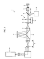
- liquid-crystal wavefront modulation device 4 that allows laser light to pass therethrough has been described by way of example; instead, a reflecting wavefront modulation device 4' may be employed, as shown in Fig. 3 .
- a reflecting wavefront modulation device 4' may be employed, as shown in Fig. 3 .
- Reference sign 13 in the drawing denotes an image-forming lens.
- the changeable mechanism 5c in which at least one of the lenses 5a and 5b constituting the Fourier transform optical system 5 is moved in the direction of the optical axis has been shown by way of example; instead, as shown in Fig. 4 , a plurality of switchable lenses 14a to 14d having different focal lengths and capable of focusing laser light at one front focal position may be mounted in a turret 15, and the switchable lenses 14a to 14d may be selected by rotating the turret 15 around a rotating shaft 15a. Furthermore, a liquid lens (see Fig. 6 ) 16 may be employed to change the focal length, and the liquid lens 16 may be moved in the direction of the optical axis so that the front focal position is maintained at a fixed position.
- the changeable mechanism 5c that changes the focal length while maintaining the front focal position of the Fourier transform optical system 5 has been shown by way of example; instead, as shown in Fig. 3 , a changeable mechanism 7c that changes the focal position by moving one or more lenses 7a and 7b of the inverse Fourier transform optical system 7 in the direction of the optical axis while maintaining the back focal position may be employed.
- a changeable mechanism 7c that changes the focal position by moving one or more lenses 7a and 7b of the inverse Fourier transform optical system 7 in the direction of the optical axis while maintaining the back focal position may be employed.
- either switchable lenses or a liquid lens may be employed instead of the zooming optical system.
- the dichroic mirror 9 be disposed between the inverse Fourier transform optical system 7 and the objective optical system 8, and that the image-forming lens 13 be provided between the dichroic mirror 9 and the image acquisition device 10, as shown in Fig. 3 .
- This has the advantage that, even if the focal length of the inverse Fourier transform optical system 7 is changed, image-acquisition can be performed without changing the magnification thereof.
- the lens 3b which is a part of the relay optical system 3, and the lens constituting the Fourier transform optical system 5 may be the same lens, as shown in Fig. 5 .
- This can reduce the number of lenses, thus allowing the configuration to be simplified.
- the liquid lens 16 whose focal length can be changed is used as the inverse Fourier transform optical system 7.
- the focal length of the inverse Fourier transform optical system 7 can be changed, changing the focal length, as shown in Fig. 6 , moves the focal position of the inverse Fourier transform optical system 7.
- an additional wavefront that moves the focal position of the Fourier transform optical system 5 by the corresponding amount of movement is applied to the laser light beams by the wavefront modulation device 4'.
- the configuration in which the inverse Fourier transform optical system 7 and the wavefront modulation device 4' constitute a changeable mechanism 17 offers the advantage of reducing the number of movable parts, simplifying the system.
Landscapes
- Physics & Mathematics (AREA)
- General Physics & Mathematics (AREA)
- Optics & Photonics (AREA)
- Chemical & Material Sciences (AREA)
- Analytical Chemistry (AREA)
- Microscoopes, Condenser (AREA)
Claims (11)
- Optisches Beleuchtungssystem (1) mit:einer Lichtquelle (11);einer Strahlablenkungseinrichtung (2) zum Ändern der Ablenkungsrichtung von Beleuchtungslicht, das von der Lichtquelle (11) emittiert wird;einer Wellenfrontmodulationsvorrichtung (4) mit einem festen Pixelpitch, die an einer optisch mit der Strahlablenkungseinrichtung (2) konjugierten Position angeordnet und dazu ausgebildet ist, die Wellenfront des Beleuchtungslichts zu modulieren;einem optischen Fourier-Transformations-System (5), welches das von der Wellenfrontmodulationsvorrichtung (4) emittierte Beleuchtungslicht fokussiert und an ihm eine Fourier-Transformation durchführt;ein optisches Inverse-Fourier-Transformations-System (7), das eine inverse Fourier-Transformation an dem von dem optischen Fourier-Transformations-System (5) emittierten Beleuchtungslicht durchführt, um einen im Wesentlichen kollimierten Lichtstrahl zu erzeugen; undein optisches Objektivsystem (8), welches das von dem optischen Inverse-Fourier-Transformations-System (7) emittierte Beleuchtungslicht auf ein Objekt (A) fokussiert,wobei das optische Fourier-Transformations-System (5) einen veränderbaren Mechanismus (5c) umfasst, der dazu ausgebildet ist, die Brennweite zu ändern, während die Fokusposition auf der Seite des optischen Inverse-Fourier-Transformations-Systems (7) an einer im Wesentlichen festen Position gehalten wird.
- Optisches Beleuchtungssystem (1) nach Anspruch 1, wobei
das optische Fourier-Transformations-System (5) eine Gruppe von mehreren Linsen (5a, 5b) mit unterschiedlichen Brennweiten umfasst; und
der veränderbare Mechanismus (5c) die Linsen (5a, 5b) auswählt. - Optisches Beleuchtungssystem (1) nach Anspruch 1, wobei
das optische Fourier-Transformations-System (5) eine Flüssiglinse (16) umfasst, deren Brennweite verändert werden kann; und
der veränderbare Mechanismus (5c) die Flüssiglinse (16) ansteuert, um ihre Brennweite zu ändern. - Optisches Beleuchtungssystem (1) nach Anspruch 1, wobei das optische Fourier-Transformations-System (5) von einem optischen Zoom-System gebildet wird.
- Optisches Beleuchtungssystem (1) mit:einer Lichtquelle (11);einer Strahlablenkungseinrichtung (2) zum Ändern der Ablenkungsrichtung von Beleuchtungslicht, das von der Lichtquelle (11) emittiert wird;einer Wellenfrontmodulationsvorrichtung (4) mit einem festen Pixelpitch, die an einer optisch mit der Strahlablenkungseinrichtung (2) konjugierten Position angeordnet und dazu ausgebildet ist, die Wellenfront des Beleuchtungslichts zu modulieren;einem optischen Fourier-Transformations-System (5), welches das von der Wellenfrontmodulationsvorrichtung (4) emittierte Beleuchtungslicht fokussiert und an ihm eine Fourier-Transformation durchführt;ein optisches Inverse-Fourier-Transformations-System (7), das eine inverse Fourier-Transformation an dem von dem optischen Fourier-Transformations-System (5) emittierten Beleuchtungslicht durchführt, um einen im Wesentlichen kollimierten Lichtstrahl zu erzeugen; undein optisches Objektivsystem (8), welches das von dem optischen Inverse-Fourier-Transformations-System (7) emittierte Beleuchtungslicht auf ein Objekt (A) fokussiert,wobei das optische Inverse-Fourier-Transformations-System (7) einen veränderbaren Mechanismus (7c) umfasst, der dazu ausgebildet ist, die Brennweite zu ändern, während die Fokusposition auf der Seite des optischen Fourier-Transformations-Systems (5) an einer im Wesentlichen festen Position gehalten wird.
- Optisches Beleuchtungssystem (1) mit:einer Lichtquelle (11);einer Strahlablenkungseinrichtung (2) zum Ändern der Ablenkungsrichtung von Beleuchtungslicht, das von der Lichtquelle (11) emittiert wird;einer Wellenfrontmodulationsvorrichtung (4) mit einem festen Pixelpitch, die an einer optisch mit der Strahlablenkungseinrichtung (2) konjugierten Position angeordnet und dazu ausgebildet ist, die Wellenfront des Beleuchtungslichts zu modulieren;einem optischen Fourier-Transformations-System (5), welches das von der Wellenfrontmodulationsvorrichtung (4) emittierte Beleuchtungslicht fokussiert und an ihm eine Fourier-Transformation durchführt;ein optisches Inverse-Fourier-Transformations-System (7), das eine inverse Fourier-Transformation an dem von dem optischen Fourier-Transformations-System (5) emittierten Beleuchtungslicht durchführt, um einen im Wesentlichen kollimierten Lichtstrahl zu erzeugen; undein optisches Objektivsystem (8), welches das von dem optischen Inverse-Fourier-Transformations-System (7) emittierte Beleuchtungslicht auf ein Objekt (A) fokussiert; undeinen veränderbaren Mechanismus (7c), der die Brennweite des Inverse-Fourier-Transformations-Systems (7) ändert und eine Wellenfront unter Verwendung der Wellenfrontmodulationsvorrichtung (4) so anwendet, dass die Fokusposition des Laserlichts durch das optische Fourier-Transformations-System (5) im Wesentlichen mit der Fokusposition des optischen Inverse-Fourier-Transformations-Systems (7) auf der Seite des optischen Fourier-Transformations-Systems (5) zusammenfällt.
- Optisches Beleuchtungssystem (1) nach Anspruch 5 oder 6, wobei
das Inverse-Fourier-Transformations-System (7) eine Gruppe von mehreren Linsen (7a, 7b) mit unterschiedlichen Brennweiten umfasst; und
der veränderbare Mechanismus (7c) die Linsen (7a, 7b) auswählt. - Optisches Beleuchtungssystem (1) nach Anspruch 5 oder 6, wobei
das optische Inverse-Fourier-Transformations-System (7) eine Flüssiglinse (16) umfasst, deren Brennweite verändert werden kann; und
der veränderbare Mechanismus (7c) die Flüssiglinse (16) ansteuert, um ihre Brennweite zu ändern. - Optisches Beleuchtungssystem (1) nach Anspruch 5 oder 6, wobei das optische Inverse-Fourier-Transformations-System (7) von einem optischen Zoom-System gebildet wird.
- Optisches Beleuchtungssystem (1) nach Anspruch 5 oder 6, ferner mit
einem optischen Relaissystem (3), das zwischen der Strahlablenkungseinrichtung (2) und der Wellenfrontmodulationsvorrichtung (4) angeordnet ist,
wobei das optische Fourier-Transformations-System (5) einen Teil des optischen Relaissystems (3) umfasst. - Optisches Beleuchtungssystem (1) nach irgendeinem der Ansprüche 1 bis 10, ferner mit einer Sehfeldblende (6), die an der Fokusposition angeordnet ist.
Applications Claiming Priority (1)
| Application Number | Priority Date | Filing Date | Title |
|---|---|---|---|
| JP2010256138 | 2010-11-16 |
Publications (2)
| Publication Number | Publication Date |
|---|---|
| EP2453285A1 EP2453285A1 (de) | 2012-05-16 |
| EP2453285B1 true EP2453285B1 (de) | 2013-04-03 |
Family
ID=45470749
Family Applications (1)
| Application Number | Title | Priority Date | Filing Date |
|---|---|---|---|
| EP11008897A Revoked EP2453285B1 (de) | 2010-11-16 | 2011-11-08 | Optisches Beleuchtungssystem |
Country Status (3)
| Country | Link |
|---|---|
| US (1) | US20120120469A1 (de) |
| EP (1) | EP2453285B1 (de) |
| JP (1) | JP5959180B2 (de) |
Families Citing this family (5)
| Publication number | Priority date | Publication date | Assignee | Title |
|---|---|---|---|---|
| DE102014010350A1 (de) | 2014-07-10 | 2016-01-14 | Carl Zeiss Meditec Ag | Augenchirurgiesystem |
| CN104102006B (zh) * | 2014-07-23 | 2016-03-30 | 哈尔滨工业大学 | 基于改进傅里叶变换的光学系统频域信息传递性能分析方法 |
| JP2017044871A (ja) | 2015-08-26 | 2017-03-02 | オリンパス株式会社 | 走査型顕微鏡 |
| DE102016108384B3 (de) * | 2016-05-04 | 2017-11-09 | Leica Microsystems Cms Gmbh | Vorrichtung und Verfahren zur lichtblattartigen Beleuchtung einer Probe |
| CN112904585B (zh) * | 2021-04-21 | 2022-11-08 | 南昌三极光电有限公司 | 一种光学系统 |
Citations (3)
| Publication number | Priority date | Publication date | Assignee | Title |
|---|---|---|---|---|
| US6348990B1 (en) | 1998-06-18 | 2002-02-19 | Hamamatsu Photonics K.K. | Spatial light modulator and spatial light modulating method |
| US6424388B1 (en) | 1995-04-28 | 2002-07-23 | International Business Machines Corporation | Reflective spatial light modulator array |
| US6560001B1 (en) | 1999-09-28 | 2003-05-06 | Hamamatsu Photonics K.K. | Spatial optical modulating device |
Family Cites Families (13)
| Publication number | Priority date | Publication date | Assignee | Title |
|---|---|---|---|---|
| JP4786027B2 (ja) * | 2000-12-08 | 2011-10-05 | オリンパス株式会社 | 光学系及び光学装置 |
| DE10227120A1 (de) * | 2002-06-15 | 2004-03-04 | Carl Zeiss Jena Gmbh | Mikroskop, insbesondere Laserscanningmikroskop mit adaptiver optischer Einrichtung |
| ES2646622T3 (es) * | 2002-07-31 | 2017-12-14 | Premium Genetics (Uk) Limited | Sistema y método de clasificación de materiales usando dirección de láser holográfica |
| JP4020734B2 (ja) * | 2002-09-13 | 2007-12-12 | オリンパス株式会社 | 走査型光学顕微鏡 |
| JP4149309B2 (ja) * | 2003-05-19 | 2008-09-10 | オリンパス株式会社 | 走査型光学顕微鏡 |
| US7492948B2 (en) * | 2003-06-26 | 2009-02-17 | Denmarks Tekniske Universitet | Generation of a desired wavefront with a plurality of phase contrast filters |
| DE10340965A1 (de) * | 2003-09-05 | 2005-03-24 | Leica Microsystems Heidelberg Gmbh | Rastermikroskop |
| JP4576137B2 (ja) * | 2004-03-19 | 2010-11-04 | オリンパス株式会社 | 顕微鏡 |
| JP4664031B2 (ja) | 2004-08-31 | 2011-04-06 | 浜松ホトニクス株式会社 | 光パターン形成方法および装置、ならびに光ピンセット装置 |
| JP4786291B2 (ja) * | 2005-10-19 | 2011-10-05 | 浜松ホトニクス株式会社 | 光ピンセット装置 |
| JP5387409B2 (ja) * | 2007-09-04 | 2014-01-15 | 株式会社ニコン | リレー変倍光学系と、これを有する顕微鏡 |
| JP2010026165A (ja) * | 2008-07-17 | 2010-02-04 | Olympus Corp | レーザー走査型顕微鏡 |
| JP5106369B2 (ja) * | 2008-12-15 | 2012-12-26 | オリンパス株式会社 | 光学装置 |
-
2011
- 2011-11-08 EP EP11008897A patent/EP2453285B1/de not_active Revoked
- 2011-11-09 US US13/292,587 patent/US20120120469A1/en not_active Abandoned
- 2011-11-16 JP JP2011250689A patent/JP5959180B2/ja not_active Expired - Fee Related
Patent Citations (3)
| Publication number | Priority date | Publication date | Assignee | Title |
|---|---|---|---|---|
| US6424388B1 (en) | 1995-04-28 | 2002-07-23 | International Business Machines Corporation | Reflective spatial light modulator array |
| US6348990B1 (en) | 1998-06-18 | 2002-02-19 | Hamamatsu Photonics K.K. | Spatial light modulator and spatial light modulating method |
| US6560001B1 (en) | 1999-09-28 | 2003-05-06 | Hamamatsu Photonics K.K. | Spatial optical modulating device |
Also Published As
| Publication number | Publication date |
|---|---|
| EP2453285A1 (de) | 2012-05-16 |
| JP2012123385A (ja) | 2012-06-28 |
| JP5959180B2 (ja) | 2016-08-02 |
| US20120120469A1 (en) | 2012-05-17 |
Similar Documents
| Publication | Publication Date | Title |
|---|---|---|
| US11719922B2 (en) | Single plane illumination microscope | |
| US10108008B2 (en) | Image-forming optical system, illumination apparatus, and observation apparatus | |
| EP2453285B1 (de) | Optisches Beleuchtungssystem | |
| EP2498116B1 (de) | Mikroskopsystem | |
| JP2010158331A (ja) | 眼科用レーザ治療装置 | |
| WO2013157606A1 (ja) | ビームエクスパンダ | |
| JP5039583B2 (ja) | 観察装置 | |
| JP6419558B2 (ja) | 観察装置 | |
| CN111095073A (zh) | 在激光扫描显微镜中扫描激发辐射和/或操纵辐射的光学组件以及激光扫描显微镜 | |
| US20170205611A1 (en) | Imaging optical system, illuminating device, and microscope apparatus | |
| EP2360505B1 (de) | Mikroskopvorrichtung | |
| CN111033350A (zh) | 在激光扫描显微镜中扫描激发辐射和/或操纵辐射的光学组件以及激光扫描显微镜 | |
| JPWO2016052743A1 (ja) | 光軸方向走査型顕微鏡装置 | |
| JP2013221953A (ja) | 照明装置、及び、それを備えた顕微鏡装置 | |
| US9690085B2 (en) | Microscope illumination apparatus, microscope, and microscope illumination method | |
| JP5603749B2 (ja) | 顕微鏡装置 | |
| JP2011064892A (ja) | 空間光変調装置、及び、それを備えたレーザ照明装置、レーザ顕微鏡 | |
| JP6385711B2 (ja) | 顕微鏡装置 | |
| JP6269239B2 (ja) | 構造化照明装置及び構造化照明顕微鏡装置 | |
| US10281699B2 (en) | Microscope system configured to irradiate focused light onto an area of a specimen outside of an optical axis of an objective lens | |
| JP2006106337A (ja) | 走査型光学顕微鏡 | |
| EP4239391A1 (de) | Ptychographisches abbildungssystem und verfahren zum aufbau eines ptychographischen abbildungssystems | |
| JP2009169108A (ja) | 観察装置 | |
| JP6355928B2 (ja) | 蛍光観察装置 | |
| JP2016109731A (ja) | 照明光学系、照明光学装置、及びこれを用いた顕微鏡 |
Legal Events
| Date | Code | Title | Description |
|---|---|---|---|
| PUAI | Public reference made under article 153(3) epc to a published international application that has entered the european phase |
Free format text: ORIGINAL CODE: 0009012 |
|
| AK | Designated contracting states |
Kind code of ref document: A1 Designated state(s): AL AT BE BG CH CY CZ DE DK EE ES FI FR GB GR HR HU IE IS IT LI LT LU LV MC MK MT NL NO PL PT RO RS SE SI SK SM TR |
|
| AX | Request for extension of the european patent |
Extension state: BA ME |
|
| 17P | Request for examination filed |
Effective date: 20120706 |
|
| RIC1 | Information provided on ipc code assigned before grant |
Ipc: G02B 21/00 20060101ALI20120809BHEP Ipc: G21K 1/00 20060101ALI20120809BHEP Ipc: G02B 21/06 20060101AFI20120809BHEP Ipc: G02B 27/00 20060101ALI20120809BHEP Ipc: G02B 27/42 20060101ALI20120809BHEP |
|
| GRAP | Despatch of communication of intention to grant a patent |
Free format text: ORIGINAL CODE: EPIDOSNIGR1 |
|
| RIN1 | Information on inventor provided before grant (corrected) |
Inventor name: FUKUSHIMA, IKUTOSHI |
|
| GRAS | Grant fee paid |
Free format text: ORIGINAL CODE: EPIDOSNIGR3 |
|
| GRAA | (expected) grant |
Free format text: ORIGINAL CODE: 0009210 |
|
| AK | Designated contracting states |
Kind code of ref document: B1 Designated state(s): AL AT BE BG CH CY CZ DE DK EE ES FI FR GB GR HR HU IE IS IT LI LT LU LV MC MK MT NL NO PL PT RO RS SE SI SK SM TR |
|
| REG | Reference to a national code |
Ref country code: GB Ref legal event code: FG4D |
|
| REG | Reference to a national code |
Ref country code: AT Ref legal event code: REF Ref document number: 605065 Country of ref document: AT Kind code of ref document: T Effective date: 20130415 Ref country code: CH Ref legal event code: EP |
|
| REG | Reference to a national code |
Ref country code: IE Ref legal event code: FG4D |
|
| REG | Reference to a national code |
Ref country code: DE Ref legal event code: R096 Ref document number: 602011001265 Country of ref document: DE Effective date: 20130529 |
|
| REG | Reference to a national code |
Ref country code: AT Ref legal event code: MK05 Ref document number: 605065 Country of ref document: AT Kind code of ref document: T Effective date: 20130403 |
|
| PG25 | Lapsed in a contracting state [announced via postgrant information from national office to epo] |
Ref country code: SI Free format text: LAPSE BECAUSE OF FAILURE TO SUBMIT A TRANSLATION OF THE DESCRIPTION OR TO PAY THE FEE WITHIN THE PRESCRIBED TIME-LIMIT Effective date: 20130403 |
|
| REG | Reference to a national code |
Ref country code: NL Ref legal event code: VDEP Effective date: 20130403 |
|
| REG | Reference to a national code |
Ref country code: LT Ref legal event code: MG4D |
|
| PG25 | Lapsed in a contracting state [announced via postgrant information from national office to epo] |
Ref country code: IS Free format text: LAPSE BECAUSE OF FAILURE TO SUBMIT A TRANSLATION OF THE DESCRIPTION OR TO PAY THE FEE WITHIN THE PRESCRIBED TIME-LIMIT Effective date: 20130803 Ref country code: NL Free format text: LAPSE BECAUSE OF FAILURE TO SUBMIT A TRANSLATION OF THE DESCRIPTION OR TO PAY THE FEE WITHIN THE PRESCRIBED TIME-LIMIT Effective date: 20130403 Ref country code: GR Free format text: LAPSE BECAUSE OF FAILURE TO SUBMIT A TRANSLATION OF THE DESCRIPTION OR TO PAY THE FEE WITHIN THE PRESCRIBED TIME-LIMIT Effective date: 20130704 Ref country code: BE Free format text: LAPSE BECAUSE OF FAILURE TO SUBMIT A TRANSLATION OF THE DESCRIPTION OR TO PAY THE FEE WITHIN THE PRESCRIBED TIME-LIMIT Effective date: 20130403 Ref country code: AT Free format text: LAPSE BECAUSE OF FAILURE TO SUBMIT A TRANSLATION OF THE DESCRIPTION OR TO PAY THE FEE WITHIN THE PRESCRIBED TIME-LIMIT Effective date: 20130403 Ref country code: ES Free format text: LAPSE BECAUSE OF FAILURE TO SUBMIT A TRANSLATION OF THE DESCRIPTION OR TO PAY THE FEE WITHIN THE PRESCRIBED TIME-LIMIT Effective date: 20130714 Ref country code: NO Free format text: LAPSE BECAUSE OF FAILURE TO SUBMIT A TRANSLATION OF THE DESCRIPTION OR TO PAY THE FEE WITHIN THE PRESCRIBED TIME-LIMIT Effective date: 20130703 Ref country code: LT Free format text: LAPSE BECAUSE OF FAILURE TO SUBMIT A TRANSLATION OF THE DESCRIPTION OR TO PAY THE FEE WITHIN THE PRESCRIBED TIME-LIMIT Effective date: 20130403 Ref country code: FI Free format text: LAPSE BECAUSE OF FAILURE TO SUBMIT A TRANSLATION OF THE DESCRIPTION OR TO PAY THE FEE WITHIN THE PRESCRIBED TIME-LIMIT Effective date: 20130403 Ref country code: PT Free format text: LAPSE BECAUSE OF FAILURE TO SUBMIT A TRANSLATION OF THE DESCRIPTION OR TO PAY THE FEE WITHIN THE PRESCRIBED TIME-LIMIT Effective date: 20130805 Ref country code: SE Free format text: LAPSE BECAUSE OF FAILURE TO SUBMIT A TRANSLATION OF THE DESCRIPTION OR TO PAY THE FEE WITHIN THE PRESCRIBED TIME-LIMIT Effective date: 20130403 |
|
| PG25 | Lapsed in a contracting state [announced via postgrant information from national office to epo] |
Ref country code: RS Free format text: LAPSE BECAUSE OF FAILURE TO SUBMIT A TRANSLATION OF THE DESCRIPTION OR TO PAY THE FEE WITHIN THE PRESCRIBED TIME-LIMIT Effective date: 20130403 Ref country code: LV Free format text: LAPSE BECAUSE OF FAILURE TO SUBMIT A TRANSLATION OF THE DESCRIPTION OR TO PAY THE FEE WITHIN THE PRESCRIBED TIME-LIMIT Effective date: 20130403 Ref country code: BG Free format text: LAPSE BECAUSE OF FAILURE TO SUBMIT A TRANSLATION OF THE DESCRIPTION OR TO PAY THE FEE WITHIN THE PRESCRIBED TIME-LIMIT Effective date: 20130703 Ref country code: HR Free format text: LAPSE BECAUSE OF FAILURE TO SUBMIT A TRANSLATION OF THE DESCRIPTION OR TO PAY THE FEE WITHIN THE PRESCRIBED TIME-LIMIT Effective date: 20130403 Ref country code: CY Free format text: LAPSE BECAUSE OF FAILURE TO SUBMIT A TRANSLATION OF THE DESCRIPTION OR TO PAY THE FEE WITHIN THE PRESCRIBED TIME-LIMIT Effective date: 20130403 Ref country code: PL Free format text: LAPSE BECAUSE OF FAILURE TO SUBMIT A TRANSLATION OF THE DESCRIPTION OR TO PAY THE FEE WITHIN THE PRESCRIBED TIME-LIMIT Effective date: 20130403 |
|
| PLBI | Opposition filed |
Free format text: ORIGINAL CODE: 0009260 |
|
| PG25 | Lapsed in a contracting state [announced via postgrant information from national office to epo] |
Ref country code: EE Free format text: LAPSE BECAUSE OF FAILURE TO SUBMIT A TRANSLATION OF THE DESCRIPTION OR TO PAY THE FEE WITHIN THE PRESCRIBED TIME-LIMIT Effective date: 20130403 Ref country code: SK Free format text: LAPSE BECAUSE OF FAILURE TO SUBMIT A TRANSLATION OF THE DESCRIPTION OR TO PAY THE FEE WITHIN THE PRESCRIBED TIME-LIMIT Effective date: 20130403 Ref country code: DK Free format text: LAPSE BECAUSE OF FAILURE TO SUBMIT A TRANSLATION OF THE DESCRIPTION OR TO PAY THE FEE WITHIN THE PRESCRIBED TIME-LIMIT Effective date: 20130403 Ref country code: CZ Free format text: LAPSE BECAUSE OF FAILURE TO SUBMIT A TRANSLATION OF THE DESCRIPTION OR TO PAY THE FEE WITHIN THE PRESCRIBED TIME-LIMIT Effective date: 20130403 |
|
| PLAX | Notice of opposition and request to file observation + time limit sent |
Free format text: ORIGINAL CODE: EPIDOSNOBS2 |
|
| 26 | Opposition filed |
Opponent name: CARL ZEISS MICROSCOPY GMBH Effective date: 20140103 |
|
| PG25 | Lapsed in a contracting state [announced via postgrant information from national office to epo] |
Ref country code: RO Free format text: LAPSE BECAUSE OF FAILURE TO SUBMIT A TRANSLATION OF THE DESCRIPTION OR TO PAY THE FEE WITHIN THE PRESCRIBED TIME-LIMIT Effective date: 20130403 Ref country code: IT Free format text: LAPSE BECAUSE OF FAILURE TO SUBMIT A TRANSLATION OF THE DESCRIPTION OR TO PAY THE FEE WITHIN THE PRESCRIBED TIME-LIMIT Effective date: 20130403 |
|
| REG | Reference to a national code |
Ref country code: DE Ref legal event code: R026 Ref document number: 602011001265 Country of ref document: DE Effective date: 20140103 |
|
| PLBB | Reply of patent proprietor to notice(s) of opposition received |
Free format text: ORIGINAL CODE: EPIDOSNOBS3 |
|
| PG25 | Lapsed in a contracting state [announced via postgrant information from national office to epo] |
Ref country code: MC Free format text: LAPSE BECAUSE OF FAILURE TO SUBMIT A TRANSLATION OF THE DESCRIPTION OR TO PAY THE FEE WITHIN THE PRESCRIBED TIME-LIMIT Effective date: 20130403 |
|
| REG | Reference to a national code |
Ref country code: FR Ref legal event code: ST Effective date: 20140731 |
|
| REG | Reference to a national code |
Ref country code: IE Ref legal event code: MM4A |
|
| PG25 | Lapsed in a contracting state [announced via postgrant information from national office to epo] |
Ref country code: IE Free format text: LAPSE BECAUSE OF NON-PAYMENT OF DUE FEES Effective date: 20131108 |
|
| PG25 | Lapsed in a contracting state [announced via postgrant information from national office to epo] |
Ref country code: FR Free format text: LAPSE BECAUSE OF NON-PAYMENT OF DUE FEES Effective date: 20131202 |
|
| PG25 | Lapsed in a contracting state [announced via postgrant information from national office to epo] |
Ref country code: SM Free format text: LAPSE BECAUSE OF FAILURE TO SUBMIT A TRANSLATION OF THE DESCRIPTION OR TO PAY THE FEE WITHIN THE PRESCRIBED TIME-LIMIT Effective date: 20130403 |
|
| PG25 | Lapsed in a contracting state [announced via postgrant information from national office to epo] |
Ref country code: TR Free format text: LAPSE BECAUSE OF FAILURE TO SUBMIT A TRANSLATION OF THE DESCRIPTION OR TO PAY THE FEE WITHIN THE PRESCRIBED TIME-LIMIT Effective date: 20130403 |
|
| REG | Reference to a national code |
Ref country code: CH Ref legal event code: PL |
|
| PG25 | Lapsed in a contracting state [announced via postgrant information from national office to epo] |
Ref country code: HU Free format text: LAPSE BECAUSE OF FAILURE TO SUBMIT A TRANSLATION OF THE DESCRIPTION OR TO PAY THE FEE WITHIN THE PRESCRIBED TIME-LIMIT; INVALID AB INITIO Effective date: 20111108 Ref country code: MK Free format text: LAPSE BECAUSE OF FAILURE TO SUBMIT A TRANSLATION OF THE DESCRIPTION OR TO PAY THE FEE WITHIN THE PRESCRIBED TIME-LIMIT Effective date: 20130403 Ref country code: LU Free format text: LAPSE BECAUSE OF NON-PAYMENT OF DUE FEES Effective date: 20131108 Ref country code: LI Free format text: LAPSE BECAUSE OF NON-PAYMENT OF DUE FEES Effective date: 20141130 Ref country code: CH Free format text: LAPSE BECAUSE OF NON-PAYMENT OF DUE FEES Effective date: 20141130 |
|
| PG25 | Lapsed in a contracting state [announced via postgrant information from national office to epo] |
Ref country code: MT Free format text: LAPSE BECAUSE OF FAILURE TO SUBMIT A TRANSLATION OF THE DESCRIPTION OR TO PAY THE FEE WITHIN THE PRESCRIBED TIME-LIMIT Effective date: 20130403 |
|
| PGFP | Annual fee paid to national office [announced via postgrant information from national office to epo] |
Ref country code: DE Payment date: 20151103 Year of fee payment: 5 |
|
| GBPC | Gb: european patent ceased through non-payment of renewal fee |
Effective date: 20151108 |
|
| RAP2 | Party data changed (patent owner data changed or rights of a patent transferred) |
Owner name: OLYMPUS CORPORATION |
|
| RAP2 | Party data changed (patent owner data changed or rights of a patent transferred) |
Owner name: OLYMPUS CORPORATION |
|
| RIN2 | Information on inventor provided after grant (corrected) |
Inventor name: FUKUSHIMA, IKUTOSHI |
|
| PG25 | Lapsed in a contracting state [announced via postgrant information from national office to epo] |
Ref country code: GB Free format text: LAPSE BECAUSE OF NON-PAYMENT OF DUE FEES Effective date: 20151108 |
|
| REG | Reference to a national code |
Ref country code: DE Ref legal event code: R119 Ref document number: 602011001265 Country of ref document: DE |
|
| RDAF | Communication despatched that patent is revoked |
Free format text: ORIGINAL CODE: EPIDOSNREV1 |
|
| STAA | Information on the status of an ep patent application or granted ep patent |
Free format text: STATUS: THE PATENT HAS BEEN GRANTED |
|
| REG | Reference to a national code |
Ref country code: DE Ref legal event code: R064 Ref document number: 602011001265 Country of ref document: DE Ref country code: DE Ref legal event code: R103 Ref document number: 602011001265 Country of ref document: DE |
|
| RDAG | Patent revoked |
Free format text: ORIGINAL CODE: 0009271 |
|
| PG25 | Lapsed in a contracting state [announced via postgrant information from national office to epo] |
Ref country code: DE Free format text: LAPSE BECAUSE OF NON-PAYMENT OF DUE FEES Effective date: 20170601 |
|
| 27W | Patent revoked |
Effective date: 20170805 |
|
| PG25 | Lapsed in a contracting state [announced via postgrant information from national office to epo] |
Ref country code: AL Free format text: LAPSE BECAUSE OF FAILURE TO SUBMIT A TRANSLATION OF THE DESCRIPTION OR TO PAY THE FEE WITHIN THE PRESCRIBED TIME-LIMIT Effective date: 20130403 |
|
| STAA | Information on the status of an ep patent application or granted ep patent |
Free format text: STATUS: PATENT REVOKED |