EP2448893B1 - Herstellung von isobuten durch spaltung von mtbe - Google Patents
Herstellung von isobuten durch spaltung von mtbe Download PDFInfo
- Publication number
- EP2448893B1 EP2448893B1 EP10725455.9A EP10725455A EP2448893B1 EP 2448893 B1 EP2448893 B1 EP 2448893B1 EP 10725455 A EP10725455 A EP 10725455A EP 2448893 B1 EP2448893 B1 EP 2448893B1
- Authority
- EP
- European Patent Office
- Prior art keywords
- column
- mtbe
- stream
- water
- isobutene
- Prior art date
- Legal status (The legal status is an assumption and is not a legal conclusion. Google has not performed a legal analysis and makes no representation as to the accuracy of the status listed.)
- Active
Links
- VQTUBCCKSQIDNK-UHFFFAOYSA-N Isobutene Chemical compound CC(C)=C VQTUBCCKSQIDNK-UHFFFAOYSA-N 0.000 title claims description 335
- 238000003776 cleavage reaction Methods 0.000 title description 97
- 230000007017 scission Effects 0.000 title description 92
- 238000002360 preparation method Methods 0.000 title description 9
- OKKJLVBELUTLKV-UHFFFAOYSA-N Methanol Chemical compound OC OKKJLVBELUTLKV-UHFFFAOYSA-N 0.000 claims description 516
- BZLVMXJERCGZMT-UHFFFAOYSA-N Methyl tert-butyl ether Chemical compound COC(C)(C)C BZLVMXJERCGZMT-UHFFFAOYSA-N 0.000 claims description 356
- 238000000034 method Methods 0.000 claims description 189
- DKGAVHZHDRPRBM-UHFFFAOYSA-N tert-butyl alcohol Substances CC(C)(C)O DKGAVHZHDRPRBM-UHFFFAOYSA-N 0.000 claims description 174
- XLYOFNOQVPJJNP-UHFFFAOYSA-N water Substances O XLYOFNOQVPJJNP-UHFFFAOYSA-N 0.000 claims description 172
- 230000008569 process Effects 0.000 claims description 94
- 238000006243 chemical reaction Methods 0.000 claims description 76
- 238000004821 distillation Methods 0.000 claims description 72
- 229930195733 hydrocarbon Natural products 0.000 claims description 72
- 150000002430 hydrocarbons Chemical class 0.000 claims description 71
- 239000000203 mixture Substances 0.000 claims description 71
- 230000015572 biosynthetic process Effects 0.000 claims description 70
- 238000000926 separation method Methods 0.000 claims description 69
- 238000003786 synthesis reaction Methods 0.000 claims description 50
- 238000004519 manufacturing process Methods 0.000 claims description 17
- 238000009833 condensation Methods 0.000 claims description 15
- 230000005494 condensation Effects 0.000 claims description 15
- 239000004215 Carbon black (E152) Substances 0.000 claims description 13
- 230000002378 acidificating effect Effects 0.000 claims description 13
- 239000007864 aqueous solution Substances 0.000 claims description 9
- 239000003513 alkali Substances 0.000 claims description 8
- 238000001816 cooling Methods 0.000 claims description 8
- 230000010354 integration Effects 0.000 claims description 6
- 239000002638 heterogeneous catalyst Substances 0.000 claims description 3
- 150000008044 alkali metal hydroxides Chemical class 0.000 claims description 2
- 229910001860 alkaline earth metal hydroxide Inorganic materials 0.000 claims description 2
- 238000002955 isolation Methods 0.000 claims 5
- 238000010494 dissociation reaction Methods 0.000 claims 3
- 230000005593 dissociations Effects 0.000 claims 3
- 239000000047 product Substances 0.000 description 94
- LCGLNKUTAGEVQW-UHFFFAOYSA-N Dimethyl ether Chemical compound COC LCGLNKUTAGEVQW-UHFFFAOYSA-N 0.000 description 88
- VXNZUUAINFGPBY-UHFFFAOYSA-N 1-Butene Chemical compound CCC=C VXNZUUAINFGPBY-UHFFFAOYSA-N 0.000 description 78
- 239000003054 catalyst Substances 0.000 description 60
- FVNIMHIOIXPIQT-UHFFFAOYSA-N 2-methoxybutane Chemical compound CCC(C)OC FVNIMHIOIXPIQT-UHFFFAOYSA-N 0.000 description 43
- 238000000605 extraction Methods 0.000 description 39
- KAKZBPTYRLMSJV-UHFFFAOYSA-N Butadiene Chemical compound C=CC=C KAKZBPTYRLMSJV-UHFFFAOYSA-N 0.000 description 32
- IAQRGUVFOMOMEM-UHFFFAOYSA-N but-2-ene Chemical class CC=CC IAQRGUVFOMOMEM-UHFFFAOYSA-N 0.000 description 30
- CPLXHLVBOLITMK-UHFFFAOYSA-N magnesium oxide Inorganic materials [Mg]=O CPLXHLVBOLITMK-UHFFFAOYSA-N 0.000 description 30
- 238000010992 reflux Methods 0.000 description 27
- 238000000066 reactive distillation Methods 0.000 description 25
- RRHGJUQNOFWUDK-UHFFFAOYSA-N Isoprene Chemical compound CC(=C)C=C RRHGJUQNOFWUDK-UHFFFAOYSA-N 0.000 description 24
- HEMHJVSKTPXQMS-UHFFFAOYSA-M sodium hydroxide Inorganic materials [OH-].[Na+] HEMHJVSKTPXQMS-UHFFFAOYSA-M 0.000 description 23
- 238000009835 boiling Methods 0.000 description 21
- 239000007789 gas Substances 0.000 description 21
- FXNDIJDIPNCZQJ-UHFFFAOYSA-N 2,4,4-trimethylpent-1-ene Chemical compound CC(=C)CC(C)(C)C FXNDIJDIPNCZQJ-UHFFFAOYSA-N 0.000 description 18
- LFQSCWFLJHTTHZ-UHFFFAOYSA-N Ethanol Chemical compound CCO LFQSCWFLJHTTHZ-UHFFFAOYSA-N 0.000 description 18
- 238000000746 purification Methods 0.000 description 15
- 239000011541 reaction mixture Substances 0.000 description 15
- 239000007788 liquid Substances 0.000 description 14
- IJDNQMDRQITEOD-UHFFFAOYSA-N n-butane Chemical class CCCC IJDNQMDRQITEOD-UHFFFAOYSA-N 0.000 description 14
- 238000010626 work up procedure Methods 0.000 description 14
- NKDDWNXOKDWJAK-UHFFFAOYSA-N dimethoxymethane Chemical compound COCOC NKDDWNXOKDWJAK-UHFFFAOYSA-N 0.000 description 13
- 239000012071 phase Substances 0.000 description 13
- 230000008901 benefit Effects 0.000 description 12
- NNPPMTNAJDCUHE-UHFFFAOYSA-N isobutane Chemical compound CC(C)C NNPPMTNAJDCUHE-UHFFFAOYSA-N 0.000 description 12
- 238000012546 transfer Methods 0.000 description 12
- XNMQEEKYCVKGBD-UHFFFAOYSA-N dimethylacetylene Natural products CC#CC XNMQEEKYCVKGBD-UHFFFAOYSA-N 0.000 description 10
- NUMQCACRALPSHD-UHFFFAOYSA-N tert-butyl ethyl ether Chemical compound CCOC(C)(C)C NUMQCACRALPSHD-UHFFFAOYSA-N 0.000 description 10
- HIXDQWDOVZUNNA-UHFFFAOYSA-N 2-(3,4-dimethoxyphenyl)-5-hydroxy-7-methoxychromen-4-one Chemical compound C=1C(OC)=CC(O)=C(C(C=2)=O)C=1OC=2C1=CC=C(OC)C(OC)=C1 HIXDQWDOVZUNNA-UHFFFAOYSA-N 0.000 description 9
- VYPSYNLAJGMNEJ-UHFFFAOYSA-N Silicium dioxide Chemical compound O=[Si]=O VYPSYNLAJGMNEJ-UHFFFAOYSA-N 0.000 description 9
- 230000000694 effects Effects 0.000 description 9
- RTZKZFJDLAIYFH-UHFFFAOYSA-N ether Substances CCOCC RTZKZFJDLAIYFH-UHFFFAOYSA-N 0.000 description 9
- 239000000446 fuel Substances 0.000 description 9
- 238000010438 heat treatment Methods 0.000 description 9
- 238000005984 hydrogenation reaction Methods 0.000 description 9
- 125000000383 tetramethylene group Chemical group [H]C([H])([*:1])C([H])([H])C([H])([H])C([H])([H])[*:2] 0.000 description 9
- -1 unsaturated C 4 hydrocarbons Chemical class 0.000 description 9
- 238000010276 construction Methods 0.000 description 8
- 239000003456 ion exchange resin Substances 0.000 description 8
- 229920003303 ion-exchange polymer Polymers 0.000 description 8
- 238000012856 packing Methods 0.000 description 8
- 239000011148 porous material Substances 0.000 description 8
- 239000000498 cooling water Substances 0.000 description 6
- 238000007700 distillative separation Methods 0.000 description 6
- 238000002474 experimental method Methods 0.000 description 6
- 229920001429 chelating resin Polymers 0.000 description 5
- 238000001035 drying Methods 0.000 description 5
- 239000012530 fluid Substances 0.000 description 5
- 239000001282 iso-butane Substances 0.000 description 5
- 239000000395 magnesium oxide Substances 0.000 description 5
- 239000011347 resin Substances 0.000 description 5
- 229920005989 resin Polymers 0.000 description 5
- 229920006395 saturated elastomer Polymers 0.000 description 5
- 238000007086 side reaction Methods 0.000 description 5
- 239000000243 solution Substances 0.000 description 5
- MYRTYDVEIRVNKP-UHFFFAOYSA-N 1,2-Divinylbenzene Chemical compound C=CC1=CC=CC=C1C=C MYRTYDVEIRVNKP-UHFFFAOYSA-N 0.000 description 4
- 102100024387 AF4/FMR2 family member 3 Human genes 0.000 description 4
- IJGRMHOSHXDMSA-UHFFFAOYSA-N Atomic nitrogen Chemical compound N#N IJGRMHOSHXDMSA-UHFFFAOYSA-N 0.000 description 4
- 101000833166 Homo sapiens AF4/FMR2 family member 3 Proteins 0.000 description 4
- OFBQJSOFQDEBGM-UHFFFAOYSA-N Pentane Chemical compound CCCCC OFBQJSOFQDEBGM-UHFFFAOYSA-N 0.000 description 4
- 229910000831 Steel Inorganic materials 0.000 description 4
- PPBRXRYQALVLMV-UHFFFAOYSA-N Styrene Chemical compound C=CC1=CC=CC=C1 PPBRXRYQALVLMV-UHFFFAOYSA-N 0.000 description 4
- 150000001336 alkenes Chemical class 0.000 description 4
- 239000000470 constituent Substances 0.000 description 4
- 230000007423 decrease Effects 0.000 description 4
- 230000008030 elimination Effects 0.000 description 4
- 238000003379 elimination reaction Methods 0.000 description 4
- 150000002170 ethers Chemical class 0.000 description 4
- 150000002500 ions Chemical class 0.000 description 4
- AXZKOIWUVFPNLO-UHFFFAOYSA-N magnesium;oxygen(2-) Chemical compound [O-2].[Mg+2] AXZKOIWUVFPNLO-UHFFFAOYSA-N 0.000 description 4
- 239000000463 material Substances 0.000 description 4
- 229910052751 metal Inorganic materials 0.000 description 4
- 239000002184 metal Substances 0.000 description 4
- 239000003921 oil Substances 0.000 description 4
- 239000012074 organic phase Substances 0.000 description 4
- 239000002245 particle Substances 0.000 description 4
- 239000000376 reactant Substances 0.000 description 4
- 238000004064 recycling Methods 0.000 description 4
- 230000009467 reduction Effects 0.000 description 4
- 239000000377 silicon dioxide Substances 0.000 description 4
- 239000007858 starting material Substances 0.000 description 4
- 239000010959 steel Substances 0.000 description 4
- 102100024378 AF4/FMR2 family member 2 Human genes 0.000 description 3
- 102100024381 AF4/FMR2 family member 4 Human genes 0.000 description 3
- 241000196324 Embryophyta Species 0.000 description 3
- 101000833172 Homo sapiens AF4/FMR2 family member 2 Proteins 0.000 description 3
- 101000833170 Homo sapiens AF4/FMR2 family member 4 Proteins 0.000 description 3
- VVQNEPGJFQJSBK-UHFFFAOYSA-N Methyl methacrylate Chemical compound COC(=O)C(C)=C VVQNEPGJFQJSBK-UHFFFAOYSA-N 0.000 description 3
- 239000002253 acid Substances 0.000 description 3
- 150000001298 alcohols Chemical class 0.000 description 3
- PNEYBMLMFCGWSK-UHFFFAOYSA-N aluminium oxide Inorganic materials [O-2].[O-2].[O-2].[Al+3].[Al+3] PNEYBMLMFCGWSK-UHFFFAOYSA-N 0.000 description 3
- 235000013844 butane Nutrition 0.000 description 3
- 238000004364 calculation method Methods 0.000 description 3
- 230000007797 corrosion Effects 0.000 description 3
- 238000005260 corrosion Methods 0.000 description 3
- 238000005661 deetherification reaction Methods 0.000 description 3
- 238000013461 design Methods 0.000 description 3
- 238000006471 dimerization reaction Methods 0.000 description 3
- 238000005516 engineering process Methods 0.000 description 3
- 238000005194 fractionation Methods 0.000 description 3
- GBMDVOWEEQVZKZ-UHFFFAOYSA-N methanol;hydrate Chemical compound O.OC GBMDVOWEEQVZKZ-UHFFFAOYSA-N 0.000 description 3
- 239000002994 raw material Substances 0.000 description 3
- 238000005406 washing Methods 0.000 description 3
- LQBZMLRJLRSDNW-ONEGZZNKSA-N (e)-1-methoxybut-2-ene Chemical compound COC\C=C\C LQBZMLRJLRSDNW-ONEGZZNKSA-N 0.000 description 2
- NWUYHJFMYQTDRP-UHFFFAOYSA-N 1,2-bis(ethenyl)benzene;1-ethenyl-2-ethylbenzene;styrene Chemical compound C=CC1=CC=CC=C1.CCC1=CC=CC=C1C=C.C=CC1=CC=CC=C1C=C NWUYHJFMYQTDRP-UHFFFAOYSA-N 0.000 description 2
- MALHZSOXIOUUQH-UHFFFAOYSA-N 3-methoxybut-1-ene Chemical compound COC(C)C=C MALHZSOXIOUUQH-UHFFFAOYSA-N 0.000 description 2
- 102100024379 AF4/FMR2 family member 1 Human genes 0.000 description 2
- 241000282326 Felis catus Species 0.000 description 2
- 101000833180 Homo sapiens AF4/FMR2 family member 1 Proteins 0.000 description 2
- CERQOIWHTDAKMF-UHFFFAOYSA-N Methacrylic acid Chemical compound CC(=C)C(O)=O CERQOIWHTDAKMF-UHFFFAOYSA-N 0.000 description 2
- LRHPLDYGYMQRHN-UHFFFAOYSA-N N-Butanol Chemical compound CCCCO LRHPLDYGYMQRHN-UHFFFAOYSA-N 0.000 description 2
- 229920002367 Polyisobutene Polymers 0.000 description 2
- QQONPFPTGQHPMA-UHFFFAOYSA-N Propene Chemical compound CC=C QQONPFPTGQHPMA-UHFFFAOYSA-N 0.000 description 2
- QAOWNCQODCNURD-UHFFFAOYSA-N Sulfuric acid Chemical compound OS(O)(=O)=O QAOWNCQODCNURD-UHFFFAOYSA-N 0.000 description 2
- 229910000272 alkali metal oxide Inorganic materials 0.000 description 2
- 239000012223 aqueous fraction Substances 0.000 description 2
- 239000008346 aqueous phase Substances 0.000 description 2
- 239000001273 butane Substances 0.000 description 2
- 229920005549 butyl rubber Polymers 0.000 description 2
- 239000006227 byproduct Substances 0.000 description 2
- 229910052799 carbon Inorganic materials 0.000 description 2
- 238000006555 catalytic reaction Methods 0.000 description 2
- 239000003795 chemical substances by application Substances 0.000 description 2
- 150000001875 compounds Chemical class 0.000 description 2
- 230000008878 coupling Effects 0.000 description 2
- 238000010168 coupling process Methods 0.000 description 2
- 238000005859 coupling reaction Methods 0.000 description 2
- 238000005336 cracking Methods 0.000 description 2
- 238000001704 evaporation Methods 0.000 description 2
- 230000008020 evaporation Effects 0.000 description 2
- 230000002349 favourable effect Effects 0.000 description 2
- 230000004992 fission Effects 0.000 description 2
- 239000002816 fuel additive Substances 0.000 description 2
- 239000003502 gasoline Substances 0.000 description 2
- 230000006872 improvement Effects 0.000 description 2
- 239000012535 impurity Substances 0.000 description 2
- ZXEKIIBDNHEJCQ-UHFFFAOYSA-N isobutanol Chemical compound CC(C)CO ZXEKIIBDNHEJCQ-UHFFFAOYSA-N 0.000 description 2
- QWTDNUCVQCZILF-UHFFFAOYSA-N isopentane Chemical compound CCC(C)C QWTDNUCVQCZILF-UHFFFAOYSA-N 0.000 description 2
- 238000002386 leaching Methods 0.000 description 2
- 239000003915 liquefied petroleum gas Substances 0.000 description 2
- 239000007791 liquid phase Substances 0.000 description 2
- 238000011068 loading method Methods 0.000 description 2
- 229910044991 metal oxide Inorganic materials 0.000 description 2
- 150000004706 metal oxides Chemical class 0.000 description 2
- BDAGIHXWWSANSR-UHFFFAOYSA-N methanoic acid Natural products OC=O BDAGIHXWWSANSR-UHFFFAOYSA-N 0.000 description 2
- CRSOQBOWXPBRES-UHFFFAOYSA-N neopentane Chemical compound CC(C)(C)C CRSOQBOWXPBRES-UHFFFAOYSA-N 0.000 description 2
- 229910052757 nitrogen Inorganic materials 0.000 description 2
- TVMXDCGIABBOFY-UHFFFAOYSA-N octane Chemical compound CCCCCCCC TVMXDCGIABBOFY-UHFFFAOYSA-N 0.000 description 2
- TWNQGVIAIRXVLR-UHFFFAOYSA-N oxo(oxoalumanyloxy)alumane Chemical compound O=[Al]O[Al]=O TWNQGVIAIRXVLR-UHFFFAOYSA-N 0.000 description 2
- YWAKXRMUMFPDSH-UHFFFAOYSA-N pentene Chemical compound CCCC=C YWAKXRMUMFPDSH-UHFFFAOYSA-N 0.000 description 2
- QMMOXUPEWRXHJS-UHFFFAOYSA-N pentene-2 Natural products CCC=CC QMMOXUPEWRXHJS-UHFFFAOYSA-N 0.000 description 2
- 239000003208 petroleum Substances 0.000 description 2
- 230000008092 positive effect Effects 0.000 description 2
- 239000002243 precursor Substances 0.000 description 2
- BDERNNFJNOPAEC-UHFFFAOYSA-N propan-1-ol Chemical compound CCCO BDERNNFJNOPAEC-UHFFFAOYSA-N 0.000 description 2
- 150000003839 salts Chemical class 0.000 description 2
- 239000011734 sodium Substances 0.000 description 2
- 239000011949 solid catalyst Substances 0.000 description 2
- 238000001179 sorption measurement Methods 0.000 description 2
- 239000000126 substance Substances 0.000 description 2
- 125000000542 sulfonic acid group Chemical group 0.000 description 2
- 230000007306 turnover Effects 0.000 description 2
- 239000002351 wastewater Substances 0.000 description 2
- CHRJZRDFSQHIFI-UHFFFAOYSA-N 1,2-bis(ethenyl)benzene;styrene Chemical compound C=CC1=CC=CC=C1.C=CC1=CC=CC=C1C=C CHRJZRDFSQHIFI-UHFFFAOYSA-N 0.000 description 1
- JJNQHLLBFBGKEL-UHFFFAOYSA-N 1-[(2-methylpropan-2-yl)oxy]butane Chemical compound CCCCOC(C)(C)C JJNQHLLBFBGKEL-UHFFFAOYSA-N 0.000 description 1
- WAEOXIOXMKNFLQ-UHFFFAOYSA-N 1-methyl-4-prop-2-enylbenzene Chemical group CC1=CC=C(CC=C)C=C1 WAEOXIOXMKNFLQ-UHFFFAOYSA-N 0.000 description 1
- IGGDKDTUCAWDAN-UHFFFAOYSA-N 1-vinylnaphthalene Chemical compound C1=CC=C2C(C=C)=CC=CC2=C1 IGGDKDTUCAWDAN-UHFFFAOYSA-N 0.000 description 1
- LAAVYEUJEMRIGF-UHFFFAOYSA-N 2,4,4-trimethylpent-2-ene Chemical compound CC(C)=CC(C)(C)C LAAVYEUJEMRIGF-UHFFFAOYSA-N 0.000 description 1
- ISRGONDNXBCDBM-UHFFFAOYSA-N 2-chlorostyrene Chemical compound ClC1=CC=CC=C1C=C ISRGONDNXBCDBM-UHFFFAOYSA-N 0.000 description 1
- UPSVYNDQEVZTMB-UHFFFAOYSA-N 2-methyl-1,3,5-trinitrobenzene;1,3,5,7-tetranitro-1,3,5,7-tetrazocane Chemical compound CC1=C([N+]([O-])=O)C=C([N+]([O-])=O)C=C1[N+]([O-])=O.[O-][N+](=O)N1CN([N+]([O-])=O)CN([N+]([O-])=O)CN([N+]([O-])=O)C1 UPSVYNDQEVZTMB-UHFFFAOYSA-N 0.000 description 1
- UPOMCDPCTBJJDA-UHFFFAOYSA-N 2-methyl-1-[(2-methylpropan-2-yl)oxy]propane Chemical compound CC(C)COC(C)(C)C UPOMCDPCTBJJDA-UHFFFAOYSA-N 0.000 description 1
- FITVQUMLGWRKKG-UHFFFAOYSA-N 2-methyl-2-propoxypropane Chemical compound CCCOC(C)(C)C FITVQUMLGWRKKG-UHFFFAOYSA-N 0.000 description 1
- JEAKTLDJVSMBKC-UHFFFAOYSA-N 2-methylpropane;2-methylprop-1-ene Chemical compound CC(C)C.CC(C)=C JEAKTLDJVSMBKC-UHFFFAOYSA-N 0.000 description 1
- OHXAOPZTJOUYKM-UHFFFAOYSA-N 3-Chloro-2-methylpropene Chemical compound CC(=C)CCl OHXAOPZTJOUYKM-UHFFFAOYSA-N 0.000 description 1
- YHQXBTXEYZIYOV-UHFFFAOYSA-N 3-methylbut-1-ene Chemical compound CC(C)C=C YHQXBTXEYZIYOV-UHFFFAOYSA-N 0.000 description 1
- OSWFIVFLDKOXQC-UHFFFAOYSA-N 4-(3-methoxyphenyl)aniline Chemical compound COC1=CC=CC(C=2C=CC(N)=CC=2)=C1 OSWFIVFLDKOXQC-UHFFFAOYSA-N 0.000 description 1
- JLBJTVDPSNHSKJ-UHFFFAOYSA-N 4-Methylstyrene Chemical compound CC1=CC=C(C=C)C=C1 JLBJTVDPSNHSKJ-UHFFFAOYSA-N 0.000 description 1
- VGGSQFUCUMXWEO-UHFFFAOYSA-N Ethene Chemical compound C=C VGGSQFUCUMXWEO-UHFFFAOYSA-N 0.000 description 1
- UFHFLCQGNIYNRP-UHFFFAOYSA-N Hydrogen Chemical compound [H][H] UFHFLCQGNIYNRP-UHFFFAOYSA-N 0.000 description 1
- ISWSIDIOOBJBQZ-UHFFFAOYSA-N Phenol Chemical compound OC1=CC=CC=C1 ISWSIDIOOBJBQZ-UHFFFAOYSA-N 0.000 description 1
- 241000183024 Populus tremula Species 0.000 description 1
- KWYUFKZDYYNOTN-UHFFFAOYSA-M Potassium hydroxide Chemical compound [OH-].[K+] KWYUFKZDYYNOTN-UHFFFAOYSA-M 0.000 description 1
- YSVZGWAJIHWNQK-UHFFFAOYSA-N [3-(hydroxymethyl)-2-bicyclo[2.2.1]heptanyl]methanol Chemical compound C1CC2C(CO)C(CO)C1C2 YSVZGWAJIHWNQK-UHFFFAOYSA-N 0.000 description 1
- 238000009825 accumulation Methods 0.000 description 1
- 150000007513 acids Chemical class 0.000 description 1
- 150000001299 aldehydes Chemical class 0.000 description 1
- 125000000217 alkyl group Chemical group 0.000 description 1
- 239000000956 alloy Substances 0.000 description 1
- 229910045601 alloy Inorganic materials 0.000 description 1
- HZVVJJIYJKGMFL-UHFFFAOYSA-N almasilate Chemical compound O.[Mg+2].[Al+3].[Al+3].O[Si](O)=O.O[Si](O)=O HZVVJJIYJKGMFL-UHFFFAOYSA-N 0.000 description 1
- 229910000323 aluminium silicate Inorganic materials 0.000 description 1
- 230000001174 ascending effect Effects 0.000 description 1
- 238000009529 body temperature measurement Methods 0.000 description 1
- LFKIGTZUWPXSIH-UHFFFAOYSA-N but-1-ene;2-methylprop-1-ene Chemical compound CCC=C.CC(C)=C LFKIGTZUWPXSIH-UHFFFAOYSA-N 0.000 description 1
- FRHGSJPFAYQFLY-UHFFFAOYSA-N but-1-ene;methanol Chemical compound OC.CCC=C FRHGSJPFAYQFLY-UHFFFAOYSA-N 0.000 description 1
- PBGVMIDTGGTBFS-UHFFFAOYSA-N but-3-enylbenzene Chemical compound C=CCCC1=CC=CC=C1 PBGVMIDTGGTBFS-UHFFFAOYSA-N 0.000 description 1
- 239000003990 capacitor Substances 0.000 description 1
- 230000003197 catalytic effect Effects 0.000 description 1
- 238000001311 chemical methods and process Methods 0.000 description 1
- 239000007795 chemical reaction product Substances 0.000 description 1
- IAQRGUVFOMOMEM-ARJAWSKDSA-N cis-but-2-ene Chemical compound C\C=C/C IAQRGUVFOMOMEM-ARJAWSKDSA-N 0.000 description 1
- 230000000052 comparative effect Effects 0.000 description 1
- 230000006835 compression Effects 0.000 description 1
- 238000007906 compression Methods 0.000 description 1
- 230000009849 deactivation Effects 0.000 description 1
- 238000006356 dehydrogenation reaction Methods 0.000 description 1
- 230000001419 dependent effect Effects 0.000 description 1
- 230000006866 deterioration Effects 0.000 description 1
- 238000011161 development Methods 0.000 description 1
- 239000000539 dimer Substances 0.000 description 1
- AFABGHUZZDYHJO-UHFFFAOYSA-N dimethyl butane Natural products CCCC(C)C AFABGHUZZDYHJO-UHFFFAOYSA-N 0.000 description 1
- HNPSIPDUKPIQMN-UHFFFAOYSA-N dioxosilane;oxo(oxoalumanyloxy)alumane Chemical compound O=[Si]=O.O=[Al]O[Al]=O HNPSIPDUKPIQMN-UHFFFAOYSA-N 0.000 description 1
- 230000008034 disappearance Effects 0.000 description 1
- 239000012153 distilled water Substances 0.000 description 1
- 238000009826 distribution Methods 0.000 description 1
- 238000004134 energy conservation Methods 0.000 description 1
- 238000005265 energy consumption Methods 0.000 description 1
- 150000002148 esters Chemical class 0.000 description 1
- 238000006266 etherification reaction Methods 0.000 description 1
- DQYBDCGIPTYXML-UHFFFAOYSA-N ethoxyethane;hydrate Chemical compound O.CCOCC DQYBDCGIPTYXML-UHFFFAOYSA-N 0.000 description 1
- 238000000895 extractive distillation Methods 0.000 description 1
- 238000011049 filling Methods 0.000 description 1
- 235000019253 formic acid Nutrition 0.000 description 1
- 238000004817 gas chromatography Methods 0.000 description 1
- 239000013529 heat transfer fluid Substances 0.000 description 1
- 238000007037 hydroformylation reaction Methods 0.000 description 1
- 239000001257 hydrogen Substances 0.000 description 1
- 229910052739 hydrogen Inorganic materials 0.000 description 1
- 150000004679 hydroxides Chemical class 0.000 description 1
- 238000010348 incorporation Methods 0.000 description 1
- 230000005764 inhibitory process Effects 0.000 description 1
- 238000009434 installation Methods 0.000 description 1
- 230000001788 irregular Effects 0.000 description 1
- 238000006317 isomerization reaction Methods 0.000 description 1
- 238000012423 maintenance Methods 0.000 description 1
- QSHDDOUJBYECFT-UHFFFAOYSA-N mercury Chemical compound [Hg] QSHDDOUJBYECFT-UHFFFAOYSA-N 0.000 description 1
- 229910052753 mercury Inorganic materials 0.000 description 1
- 238000005649 metathesis reaction Methods 0.000 description 1
- 239000002032 methanolic fraction Substances 0.000 description 1
- 239000002808 molecular sieve Substances 0.000 description 1
- 150000005673 monoalkenes Chemical group 0.000 description 1
- 238000000465 moulding Methods 0.000 description 1
- JRZJOMJEPLMPRA-UHFFFAOYSA-N olefin Natural products CCCCCCCC=C JRZJOMJEPLMPRA-UHFFFAOYSA-N 0.000 description 1
- 238000006384 oligomerization reaction Methods 0.000 description 1
- 239000008188 pellet Substances 0.000 description 1
- HGBOYTHUEUWSSQ-UHFFFAOYSA-N pentanal Chemical compound CCCCC=O HGBOYTHUEUWSSQ-UHFFFAOYSA-N 0.000 description 1
- 238000005373 pervaporation Methods 0.000 description 1
- 238000005191 phase separation Methods 0.000 description 1
- 238000002459 porosimetry Methods 0.000 description 1
- 239000002244 precipitate Substances 0.000 description 1
- 238000012545 processing Methods 0.000 description 1
- HJWLCRVIBGQPNF-UHFFFAOYSA-N prop-2-enylbenzene Chemical compound C=CCC1=CC=CC=C1 HJWLCRVIBGQPNF-UHFFFAOYSA-N 0.000 description 1
- 239000012429 reaction media Substances 0.000 description 1
- 230000001603 reducing effect Effects 0.000 description 1
- 230000001105 regulatory effect Effects 0.000 description 1
- 230000000630 rising effect Effects 0.000 description 1
- 238000005070 sampling Methods 0.000 description 1
- 238000010517 secondary reaction Methods 0.000 description 1
- 239000010865 sewage Substances 0.000 description 1
- 238000004904 shortening Methods 0.000 description 1
- 238000005029 sieve analysis Methods 0.000 description 1
- 235000012239 silicon dioxide Nutrition 0.000 description 1
- 229910052814 silicon oxide Inorganic materials 0.000 description 1
- URGAHOPLAPQHLN-UHFFFAOYSA-N sodium aluminosilicate Chemical compound [Na+].[Al+3].[O-][Si]([O-])=O.[O-][Si]([O-])=O URGAHOPLAPQHLN-UHFFFAOYSA-N 0.000 description 1
- 239000007787 solid Substances 0.000 description 1
- 238000010561 standard procedure Methods 0.000 description 1
- 238000006277 sulfonation reaction Methods 0.000 description 1
- 230000008961 swelling Effects 0.000 description 1
- 238000012360 testing method Methods 0.000 description 1
- IAQRGUVFOMOMEM-ONEGZZNKSA-N trans-but-2-ene Chemical compound C\C=C\C IAQRGUVFOMOMEM-ONEGZZNKSA-N 0.000 description 1
- 229920002554 vinyl polymer Polymers 0.000 description 1
Images


Classifications
-
- C—CHEMISTRY; METALLURGY
- C07—ORGANIC CHEMISTRY
- C07C—ACYCLIC OR CARBOCYCLIC COMPOUNDS
- C07C1/00—Preparation of hydrocarbons from one or more compounds, none of them being a hydrocarbon
- C07C1/20—Preparation of hydrocarbons from one or more compounds, none of them being a hydrocarbon starting from organic compounds containing only oxygen atoms as heteroatoms
- C07C1/22—Preparation of hydrocarbons from one or more compounds, none of them being a hydrocarbon starting from organic compounds containing only oxygen atoms as heteroatoms by reduction
-
- C—CHEMISTRY; METALLURGY
- C07—ORGANIC CHEMISTRY
- C07C—ACYCLIC OR CARBOCYCLIC COMPOUNDS
- C07C11/00—Aliphatic unsaturated hydrocarbons
- C07C11/02—Alkenes
- C07C11/08—Alkenes with four carbon atoms
- C07C11/09—Isobutene
-
- B—PERFORMING OPERATIONS; TRANSPORTING
- B01—PHYSICAL OR CHEMICAL PROCESSES OR APPARATUS IN GENERAL
- B01J—CHEMICAL OR PHYSICAL PROCESSES, e.g. CATALYSIS OR COLLOID CHEMISTRY; THEIR RELEVANT APPARATUS
- B01J31/00—Catalysts comprising hydrides, coordination complexes or organic compounds
- B01J31/02—Catalysts comprising hydrides, coordination complexes or organic compounds containing organic compounds or metal hydrides
-
- C—CHEMISTRY; METALLURGY
- C07—ORGANIC CHEMISTRY
- C07C—ACYCLIC OR CARBOCYCLIC COMPOUNDS
- C07C1/00—Preparation of hydrocarbons from one or more compounds, none of them being a hydrocarbon
- C07C1/20—Preparation of hydrocarbons from one or more compounds, none of them being a hydrocarbon starting from organic compounds containing only oxygen atoms as heteroatoms
-
- C—CHEMISTRY; METALLURGY
- C07—ORGANIC CHEMISTRY
- C07C—ACYCLIC OR CARBOCYCLIC COMPOUNDS
- C07C7/00—Purification; Separation; Use of additives
- C07C7/04—Purification; Separation; Use of additives by distillation
- C07C7/05—Purification; Separation; Use of additives by distillation with the aid of auxiliary compounds
- C07C7/08—Purification; Separation; Use of additives by distillation with the aid of auxiliary compounds by extractive distillation
Definitions
- the present invention relates to a process for the preparation of isobutene by cleavage of MTBE.
- Isobutene is the starting material for the production of a variety of products, eg. For the production of butyl rubber, polyisobutylene, isobutene oligomers and t-butylaromatics.
- isobutene can be used as a precursor for the production of methacrylic acid and its esters.
- isobutene In technical streams, for example in the C4 cut from petroleum crackers, isobutene is frequently present together with saturated and unsaturated C 4 hydrocarbons. From these mixtures isobutene can not be separated economically by distillation because of the low boiling point difference or the very low separation factor between isobutene and 1-butene by distillation. Therefore, isobutene is usually recovered from technical hydrocarbon mixtures by reacting isobutene to a derivative that is easily separated from the remaining hydrocarbon mixture and that the isolated derivative is cleaved back to isobutene and derivatizing agent.
- isobutene is therefore normally separated as follows: After removal of most of the polyunsaturated hydrocarbons, mainly butadiene, by extraction (selective distillation) or selective hydrogenation to linear butenes, the remaining mixture (raffinate I or hydrogenated crack C 4 ) reacted with alcohol or water. In the reaction of the isobutene with water, tert-butanol (TBA) is formed; when using alcohol, the alkyl tert-butyl ether is formed, the alkyl group being determined by the alcohol used. When using methanol is methyl tert-butyl ether (MTBE), which formed using ethanol ethyl tert-butyl ether (ETBE).
- MTBE methyl tert-butyl ether
- ETBE ethanol ethyl tert-butyl ether
- Both components are primarily used as a component for increasing the octane number of gasoline fuels.
- the conversion of isobutene with ethanol to ETBE has become industrially relevant only in the last decade, since the legislation has a share of renewable raw material in the fuel and bioethanol is sufficiently available.
- the etherification with C 3 - or C 4 -alcohols has likewise been described in the context of processes for the production of isobutene ( US 4,287,379 ; US 4,320,232 ). After their separation, both the ethers and TBA can be cleaved to isobutene in inversion of their formation.
- the great advantage of the reaction with alcohols is that in this case a very high conversion of isobutene can be achieved.
- the cleavage of the MTBE can take place in the liquid or gas phase.
- Typical side reactions include the formation of water and dimethyl ether (DME) from methanol and the formation of di- and oligomers of isobutene (mainly C8, C12 hydrocarbons).
- the C4 hydrocarbons used for the MTBE synthesis are usually water-saturated (about 200-400 ppm water).
- water can enter the synthesis via the alcohol used.
- the methanol fractions separated in the MTBE cleavage often still contain water from the DME formation of the cleavage.
- Water is at least partially converted to TBA in the MTBE synthesis.
- the TBA formed can be separated in the purification of the discharge from the synthesis prior to cleavage. As a result, this proportion of the isobutene contained in the raw material for isobutene production is lost.
- the aim of the process according to the invention was therefore to use the resulting in the synthesis TBA at least partially for the production of isobutene.
- the patent EP 0 869 107 discloses a process for producing 1-butene, isobutene and MTBE. From a 1-butene and isobutene-containing mixture of hydrocarbons, the isobutene is separated by MTBE formation and distillation and then catalytically cleaved. The products of the cleavage are separated into an isobutene-rich fraction and a fraction containing most of the methanol formed, optionally undecomposed ether and optionally heavy compounds. This fraction is optionally partially recycled to the synthesis. In specific embodiments, part of the MTBE is used as a motor fuel fraction.
- the process according to the invention is characterized in that the water content in process step e) is reduced to less than 1% by mass in fraction (VIII).
- the advantage of the method according to the invention lies not only in the use of the TBA-bound isobutene for the cleavage.
- As additional power only a relatively small amount of waste water is generated, which can be supplied to a sewage treatment plant, for example. If, on the other hand, TBA were removed from the process as a separate stream, it would have to be recycled separately.
- TBA were removed from the process as a separate stream, it would have to be recycled separately.
- the way in which a separation or mixture into a residual stream MTBE, which is often marketed for example as a gasoline fuel is limited. For example, in Europe, the typical specification for marketable MTBE is 98% ether content.
- a leaching stream can be metered in process step d) or in process step e) of the process according to the invention.
- a further advantage of the process according to the invention is that the lye can be easily removed from the process together with the water fraction in the water separation in process step e). There is thus no risk that the lye is recycled in process step a) and, if appropriate, leads to damage of the catalyst used here.
- Suitable isobutene-containing C4 streams are, for example, light petroleum fractions from refineries, C4 fractions from crackers (for example steam crackers, hydrocrackers, cat crackers), mixtures of Fischer-Tropsch syntheses, mixtures from the dehydrogenation of butanes, mixtures from skeletal isomerization of linear butenes and mixtures, formed by metathesis of olefins.
- C4 fractions from crackers for example steam crackers, hydrocrackers, cat crackers
- Fischer-Tropsch syntheses mixtures from the dehydrogenation of butanes
- mixtures from skeletal isomerization of linear butenes and mixtures formed by metathesis of olefins.
- C4 fractions from steam crackers which are primarily used for the production of ethene and propene, and in which, for example, refinery gases, naphtha, gas oil, LPG (liquefied petroleum gas) and NLG (natural liquified gas) are used, or C4 fuels are used.
- Fractions from cat crackers the by-produced C4 cuts contain different amounts of isobutene, 1,3-butadiene, 1-butene, c-2-butene, t-2-butene, n-butane and i-butane.
- the isobutene-containing C 4 hydrocarbons used in the process according to the invention preferably have a content of 1,3-butadiene of less than 1% by mass, more preferably less than 0.5% by mass.
- Typical isobutene-containing C4-hydrocarbon mixtures are e.g. hydrogenated CC4 (HCC4) and raffinate I.
- Hydrogenated CC4 is obtained, for example, by known technical processes by selective hydrogenation of the polyunsaturated hydrocarbons present in the CC4. In this case, for example, 1,3-butadiene mainly 1-butene and 2-butenes are formed.
- Raffinate I is obtained by separation of 1,3-butadiene and other polyunsaturated hydrocarbons from CC4. This can be done by known methods, for example by extractive distillation.
- Table 1 below shows typical mass fractions of the skin components of CC4, HCC4 and Raffinate I.
- Table 1 shows typical composition of CC4, HCC4 and raffinate I.
- component CC4 (S) HCC4 Raffinate I isobutane 0.6 - 6 0.6 - 6 1 - 10 n-butane 0,5 - 8 0.5-10 0.8 - 13 1-butene 9 - 25 24 - 67 15 - 42 isobutene 10 - 35 10 - 35 17 - 58 2-butene 4 - 20 14 - 48 6 - 33 1,3-butadiene 25 - 70 0 - 1 0 - 1 C1-C3-kWh 0 - 1 0 - 1 0 - 2 explanation CC4 (S): typical of a C4 mixture obtained from the crack C4 of a steam cracker (High Severity) without additional moderation of the catalyst.
- KWSt hydrocarbons All figures in% by mass
- the mixture of C4 hydrocarbons obtained after partial or complete separation of isobutene from raffinate I or HCC4 is generally referred to as Raffinate II called.
- the residual content of isobutene in the raffinate II varies with the processes of isobutene separation and is normally less than 5% by mass.
- Particularly preferred in the process according to the invention are used as isobutene-containing C4-hydrocarbons (II) HCC4, raffinate I, mixtures thereof or mixtures thereof with raffinate II streams.
- the C4 hydrocarbon streams used may contain water until saturated. Typical is a water content of 200 - 400 ppm.
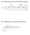
- the isobutene (I) present in the isobutene-containing C4-hydrocarbons (II) is reacted with methanol (III) on acidic ion exchangers to give a MTBE- and TBA-containing reaction mixture (IV).
- methanol (III) on acidic ion exchangers to give a MTBE- and TBA-containing reaction mixture (IV).
- all known processes for MTBE synthesis can be used for this purpose, for example, the MTBE synthesis analogous to the description in DE 101 02 082 respectively.
- the MTBE synthesis in process step a) is preferably carried out in at least two, more preferably in three fixed bed reactors.
- reactors in which the methanol (III) is reacted with the isobutene (I) to close to the thermodynamic equilibrium conventional fixed bed reactors (tube-bundle reactors, adiabatic fixed-bed reactors, circulation reactors) can be used. They can be with or without partial feedback, taking optionally the recycle stream can be cooled, operated.
- a MTBE- and TBA-containing reaction mixture (IV) is withdrawn, which contains as further constituents, inter alia unreacted C4 hydrocarbons, 2-methoxybutane, C8 hydrocarbons, DME and residual amounts of methanol.
- the conversion of the isobutene preferably takes place up to the setting of the thermodynamic equilibrium of MTBE, methanol and isobutene, preferably an isobutene conversion of greater than 90, more preferably greater than 95%, very preferably greater than 98% is set or achieved.
- the reactors are preferably operated at a temperature of 20 to 110 ° C, preferably 25 to 70 ° C and a pressure of 0.5 to 5 MPa, preferably 0.7 to 2 MPa (abs).
- the first of the reactors is operated at higher temperature for the purpose of high reaction rate than the following ones in which the equilibrium position is utilized.
- the first of the reactors is operated at a temperature of 35 to 70 ° C and the subsequent reactors are operated at a temperature of 25 to 50 ° C.
- the methanol (III) is fed to the reaction in step a) via one or more methanol-containing streams which may contain further components.
- methanol-containing streams are recycled: fresh, so not recovered in the process according to the invention, methanol (to compensate for methanol losses due to MTBE removal or DME formation), the methanol-containing fraction (VIII) and streams in the Fractionation of water and methanol from extractions incurred.
- Methanol (III) in the context of this invention refers to the sum of the pure methanol contained in these streams.
- MTBE MTBE
- TBA Water
- C8 hydrocarbons and isoprene be included.
- the molar ratio of methanol (III) to isobutene in the feed to the first reactor of process step a) is preferably in the range from 10 to 1 to 1 to 1, more preferably from 5 to 1 to 1.1 to 1 and most preferably in the range from 1.8 to 1 to 1.2 to 1.
- Suitable ion exchange resins are, for example, those prepared by sulfonation of phenol / aldehyde condensates or cooligomers of vinyl aromatic compounds.
- aromatic vinyl compounds for preparing the cooligomers are: styrene, vinyltoluene, vinylnaphthalene, vinylethylbenzene, methylstyrene, vinylchlorobenzene, vinylxylene and divinylbenzene.
- the co-oligomers formed by reacting styrene with divinylbenzene are used as precursors for the preparation of ion exchange resins having sulfonic acid groups.
- the resins can be prepared gel-like, macroporous or spongy.
- the properties of these resins, especially specific surface area, porosity, stability, swelling and exchange capacity, can be varied by the manufacturing process.
- the pore volume of the ion exchange resins used as catalysts is preferably from 0.3 to 0.9 ml / g, in particular from 0.5 to 0.9 ml / g.
- the grain size of the resins is preferably from 0.3 mm to 1.5 mm, in particular from 0.5 mm to 1.0 mm.
- the particle size distribution can be narrowed or further selected.
- ion exchange resins having a very uniform grain size can be used.
- the capacity of the ion exchanger based on the delivery form, preferably from 0.7 to 2.0 eq / l, in particular from 1.1 to 2.0 eq / l or preferably from 0.5 to 5.5 mol / kg, in particular from 0.8 to 5.5 mol / kg.
- the information on the capacity in mol / kg refer to each up to constant weight in the warm nitrogen stream at z. B. 105 ° C dried ion exchange resin.
- the ion exchange resins can be used in their H form.
- Strong acidic resins of the styrene-divinylbenzene type which are preferably used, are disclosed in U.S. Pat. a. sold under the following trade names: Amberlyst® 15, Amberlyst® 35 (each Rohm & Haas) or Lewatit® K2621 (Lanxess).
- the separation by distillation of the MTBE- and TBA-containing fraction (V) from the reaction mixture (IV) can be carried out in the simplest case in a single column.
- the fraction (V) is obtained as the bottom product.
- the distillate consists mainly of unreacted C4 hydrocarbons, which also contain methanol due to the azeotrope formation with methanol, and DME.
- the bottom product contains, in addition to TBA and MTBE, 2-methoxybutane and C8-hydrocarbons.
- methanol may also be present.
- the distillation column preferably has 15 to 55 theoretical plates, preferably 20 to 40 and particularly preferably 25 to 35.
- the feed of the column is preferably added between steps 10 and 30 (from above), preferably between steps 15 and 25.
- the column is preferably at a pressure of 0.3 to 2.5 MPa (abs), preferably at 0.5 to 1.0 MPa (abs) operated.
- the reflux ratio depending on the number of stages realized, the composition of the reactor effluent and the required purity of distillate and bottom product, preferably less than 5, preferably less than 2. As reflux ratio is defined by the ratio of the reflux flow in the column to the discharged distillate.
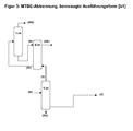
- AFF1 we in the column the MTBE and TBA-containing fraction (V) taken as side draw.
- the bottom product is a fraction in which C8 hydrocarbons are enriched and thus discharged from the process.
- the separation of C8 and optionally C8 + hydrocarbons has the advantage that little or no of them reach the cleavage reactor. As a result, the catalyst is protected in the MTBE cleavage from occupancy with high boilers, whereby the risk of reducing activity and shortening the service life of the catalyst is reduced.
- a distillation column in which the MTBE- and TBA-containing fraction (V) removed as side draw preferably has 20 to 65 theoretical plates, preferably 25 to 55 and particularly preferably 30 to 45.
- the feed of the column is preferably between stage 10 and
- the removal of the side stream is preferably carried out below the addition of the feed, preferably between 5 and 25, more preferably between 10 and 20 stages below the feed and preferably between 5 and 20 stages above the sump removal, preferably 10 and 15 stages above.
- the column is preferably operated at a pressure of 0.3 to 2.5 MPa (abs), preferably at 0.5 to 1.0 MPa (abs).
- the reflux ratio is, depending on the number of stages realized, the composition of the reactor effluent and the required purities of distillate and bottom product, preferably less than 5, preferably less than 2.
- the column is carried out as a reactive distillation. This has the advantage that additional isobutene unconverted in process step a) is converted to MTBE.
- the reactive distillation column is in a pressure range of 0.3 to 2.5 MPa (abs), preferably 0.5 to 1.0 MPa (abs) and at a temperature in the reaction zone of 50 to 90 ° C, preferably 55 to 70 ° C operated at a reflux ratio between 0.5 and 1.5, preferably between 0.7 and 0.9.
- the reactive distillation column preferably has a region of purely distillative separation above the catalyst packing.
- the zone above the catalyst packing preferably has 5 to 25, in particular 10 to 15, separation stages.
- the separation zone below the catalyst comprises 10 to 40, in particular 20 to 30, separation stages.
- the feed to the reactive distillation column can be carried out above or below, preferably below the catalyst zone.
- the feed to the reactive distillation column is preferably carried out below the reactive packing, preferably 3 to 13, more preferably 4 to 10 theoretical plates below the reactive packing.
- the catalyst zone can be estimated with a distillative effect of 1 to 5 theoretical plates per meter packing height.
- the height of the catalyst zone / reactive zone can be determined by simple preliminary tests, depending on the desired isobutene conversion.
- the amount of catalyst is preferably chosen so large that an isobutene conversion of 75 to 99%, preferably from 85 to 98% and particularly preferably from 95 to 97% based on the isobutene content in the feed to the reactive distillation is achieved.
- an acidic ion exchange resin is used as in process step a).
- the catalyst can either be integrated in the packing, for example KataMax® (as in EP 0 428 265 described), KataPak® (as in EP 0 396 650 or DE 298 07 007.3 U1 described) or on shaped bodies (as in US 5,244,929 be described).
- the hydraulic load in the catalytic packing of the column is preferably 10% to 110%, preferably 20% to 70% of its flood point load.
- Hydraulic loading of a distillation column is understood to be the uniform flow stress of the column cross-section due to the ascending vapor mass flow and the returning liquid mass flow.
- the upper load limit marks the maximum Loading by steam and return liquid, above which the separation effect due to entrainment or jamming of the return liquid by the rising vapor stream decreases.
- the lower load limit indicates the minimum load below which the separation effect decreases or collapses due to irregular flow or emptying of the column -.
- B. the floors. ( Vauck / Müller, "Basic Operations of Chemical Process Engineering", p. 626, VEB Deutscher Verlag für Grundstoffindustrie .)
- isobutene residual concentrations of less than 1000 ppm by mass (wppm), preferably 800 wppm and more preferably less than 500 wppm, based on the C4 mixture in the distillate, can be obtained.
- methanol excess should be limited in such a way that on the one hand a sufficient amount of methanol for the forming azeotrope of methanol and C4 hydrocarbons is present, on the other hand not so much that excessively much methanol in the bottom product geriete, so preferably a MTBE with a methanol content below 10,000 wppm, more preferably below 5000 wppm.
- additional methanol can be fed to the reactive distillation column. This can be done together with the feed from process step a) or else at one point or at several points of the reactive distillation column, for. B. at the top of the column and / or on, between and / or under the catalyst bed.
- the separated as distillate methanol-containing C4 hydrocarbons can be further processed in various work-up variants.
- the methanol is separated from the methanol-containing C4 hydrocarbons obtained as distillate.
- the separation of the methanol from the top product can be carried out in particular by extraction with water or an aqueous solution as a washing medium. Preference is given to using an aqueous solution having a pH of greater than or equal to 8, preferably from 8 to 12.
- the adjustment of the pH can z. B. by addition of sodium hydroxide solution and / or sulfuric acid.
- This extraction according to the known standard methods of technology can be carried out, for example, in an extraction column or in a cascade of mixers and separating containers.
- the separation of the methanol with water or an aqueous solution is carried out as a washing medium in an extraction column.
- the residual content of alcohol is preferably lowered to below 0.2% by mass, more preferably below 500 ppm by weight, very particularly preferably below 50 ppm by weight.
- the extraction column preferably has from 2 to 25, more preferably from 5 to 15 theoretical plates and is preferably operated at temperatures of 10 to 90 ° C and pressures of at least 0.1 MPa above the vapor pressure of the C4 hydrocarbons.
- the mass ratio of washing medium to top product fed is preferably from 1 to 5 to 1 to 40.
- the alcohol-laden wash water from the extraction is preferably worked up in a separate unit and the water is at least partially recycled to the extraction.
- the workup can be carried out for example by distillation, in which a virtually alcohol-free water fraction in the bottom and methanol are obtained as top product.
- the methanol can be recycled back to step a) of the process according to the invention.
- the methanol-free C4-Kohlenwaserstoffe obtained from the extraction can be worked up by known methods to highly pure 1-butene. For this For example, first in a selective hydrogenation, traces of polyunsaturated hydrocarbons are hydrogenated (eg DE 31 43 647 ) and then separated by first two times fractionation n-butane and 2-butenes, then isobutane and other low-boiling components of 1-butene. The 2-butenes and the n-butane separated off during the first fractionation may, for example, in an oligomerization to give C8-olefins (eg. OCTOL process, s. Hydrocarbon Process, Int. Ed. (1986) 65, pp. 31-33 ) or further processed in a hydroformylation to valeraldehyde.
- C8-olefins eg. OCTOL process, s. Hydrocarbon Process, Int. Ed. (1986) 65, pp. 31-33
- these are first fed to a further reaction stage in order to further reduce the isobutene content.
- This reaction is preferably carried out in one or two adiabatic fixed bed reactors, as catalysts, the same as in process step a) are used.
- the temperatures at which the reaction is carried out are preferably from 20 to 60 ° C, preferably from 30 to 50 ° C, the pressure preferably from 0.5 to 5 MPa, preferably from 0.7 to 2 MPa.
- additional methanol is fed into the reaction stage, so that the methanol content at the outlet of the reactors is preferably 1-10% by mass.
- the effluent from the reaction stage is separated in a distillation column to give methanol-containing C4 hydrocarbons as the distillate.
- This distillation can also be carried out as a reactive distillation.
- the C4 hydrocarbons can be further processed by extraction, selective hydrogenation and distillation analogous to the first work-up variant.
- the bottoms product is an MTBE stream which normally still contains methanol. It can be recycled separately or recycled in whole or in part in process step a).
- the distillative separation of the reaction mixture (IV) can be operated with less effort, so that even portions of MTBE remain in the distillate stream. This reduces the amount of energy required.
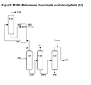
- AFF3 of process step b) becomes after the first column for the separation of the reaction mixture (IV), the MTBE bottom product of the first column is further purified in a second column.
- high boilers, above all C8 hydrocarbons, are removed as bottom product.
- Another object of this column may be the partial or complete removal of 2-methoxybutane, because 2-methoxybutane can be cleaved in the reactor to linear butenes and methanol. Linear butenes may jeopardize the isobutene specification if the concentration is too high.
- the column is operated at a pressure which allows as much of the TBA contained in the feed as possible to reach the distillate (formation of a pressure azeotrope).
- the column pressure is therefore, regardless of whether only DIB or additionally 2-methoxybutane to be separated, preferably at 0.3 to 2.0 MPa (abs) .
- the overhead condenser is preferably operated as a partial condenser and the overhead product (V) is taken off in vapor form.
- the overhead product withdrawn in vapor can then be fed directly or after further preheating the reactor.
- the pressure difference between distillation and reactor is in this case preferably at least 0.05 MPa (abs) .
- the reaction pressure in the cleavage reactor is 0.7 MPa (abs)
- the distillation pressure should preferably be at least 0.75 MPa (abs) .
- the column has 15 to 60 theoretical plates, preferably 20 to 55 and preferably 30 to 45 theoretical plates.
- the reflux ratio in the context of the present invention defined as the mass flow of the return divided by the Mass flow of the distillate is, depending on the number of stages realized, the composition of the MTBE used and the required purity, preferably adjusted to a value of 0.5 to 7, preferably from 1 to 4.
- the distillation column used preferably has from 50 to 140 theoretical plates, preferably from 60 to 120 and very particularly preferably from 80 to 110.
- the reflux ratio is, depending on the number of stages realized, the composition of the MTBE used and the required purity, preferably from 1 to 20, preferably from 3 to 10.
- the bottom product of the column contains the high boilers diisobutene and 2-methoxybutane and MTBE. If primarily diisobutene is to be separated in the column, the MTBE content in the bottom product can be reduced to values of less than 25% by mass. If additional 2-methoxybutane are to be separated off, it is expedient to allow a higher MTBE content in the bottom product between 60 and 85% by mass on account of the small difference in boiling point between 2-methoxybutane and MTBE, in order to reduce the expenditure for the separation. In both cases, this mixture can be used thermally, be used as starting material for a synthesis gas plant or used directly or after hydrogenation as a fuel component.
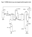
- a further distillation column for the separation of by-products is connected between the two columns of the AFF3.
- overhead-boiling components are completely or partially separated as distillate.
- medium-boiling components in the context of this invention are components having a boiling point between the C4 hydrocarbons and MTBE or the Understood MTBE / methanol azeotrope. Examples include dimethoxymethane and C5 hydrocarbons such as n-pentane, isopentane, neopentane, 1-pentene, 2-pentene, 3-methyl-1-butene and isoprene. Residues of optionally still contained C4 hydrocarbons are separated together with the medium-boiling components.
- the proportion of medium-boiling components in the feed to the column is generally not high, and is preferably below 2%, preferably below 0.5%.
- the distillation column preferably has from 30 to 75 theoretical plates, preferably from 40 to 65 and particularly preferably from 40 to 55 theoretical plates.
- the column depending on the realized number of stages, the composition of the MTBE used and the required purity of medium-boiling components with a reflux ratio between 150 and 350, in particular operated between 200 and 300.
- the column is preferably operated at an operating pressure of 0.2 to 0.6 MPa (abs) , preferably from 0.3 to 0.4 MPa (abs) .
- To heat the column can, for. B. steam can be used.
- the condensation can take place against the cooling sole, cooling water or air.
- the top hatch of the column can be completely or only partially condensed, so that the top product can be withdrawn either liquid or vapor.
- the overhead product can be used, for example, thermally or used as starting material of a synthesis gas plant.
- the MTBE- and TBA-containing fraction (V) separated in process step b) preferably has a content of MTBE of greater than 95% by mass, particularly preferably greater than 98% by mass.
- the proportion of TBA is preferably from 0.05 to 5% by mass, preferably from 0.2 to 2.0% by mass, most preferably at 0.2 to 1.0 mass%.
- MTBE and TBA methanol may be present, preferably 0 to 5% by mass, preferably 0.1 to 1 mass%.
- the content of 2-methoxybutane is preferably 0 to 1.0% by mass, preferably 0.05 to 0.5% by mass, more preferably 0.08 to 0.3% by mass.
- the content of C 8 -hydrocarbons is preferably from 0 to 1% by mass, preferably from 0 to 0.1% by mass, more preferably from 0 to 0.01% by mass.
- Typical other components included are 3-methoxy-1-butene, 1-methoxy-2-butene, dimethoxymethane and C5 hydrocarbons.
- step c) of the process according to the invention the MTBE and TBA-containing fraction (V) is completely or partially fed to a cleavage reaction where it reacts on a heterogeneous catalyst in the gas phase to at least isobutene, methanol, MTBE and water and optionally TBA-containing cleavage products ( VI) is split.
- a heterogeneous catalyst in the gas phase to at least isobutene, methanol, MTBE and water and optionally TBA-containing cleavage products ( VI) is split.
- all solid catalysts can be used which effect the cleavage of MTBE to isobutene and methanol in the temperature range 120 to 400 ° C, in particular in the range of 180 to 350 ° C.
- the process according to the invention is preferably carried out in such a way that the largest possible part of the MTBE produced in step a) is supplied to step c). It is therefore particularly suitable for the production of pure isobutene from isobutene-containing C 4 -hydrocarbons, if a high proportion of the isobutene present in the C 4 -hydrocarbons is to be obtained as pure isobutene.
- the occurring in the process MTBE-rich streams proportionally different, for example, for use as a fuel additive can be used.
- the catalysts used in the process according to the invention can, for.
- catalysts which formally consist of magnesium oxide, aluminum oxide and silicon oxide are preferably used for cleaving MTBE to isobutene and methanol in the gas phase. Such catalysts are z. In US 5,171,920 in Example 4 or in EP 0 589 557 described.
- catalysts which have formally magnesium oxide, aluminum oxide and silicon dioxide and which have a magnesium oxide content of from 0.5 to 20% by mass, preferably from 5 to 15% by mass and more preferably from 10 to 15% by mass, an alumina content of 4 to 30% by mass, preferably 10 to 20% by mass, and a silica content of 60 to 95% by mass, preferably 70 to 90% by mass.
- the catalyst has an alkali metal oxide in addition to the magnesium oxide. This can be z. B. be selected from Na 2 O or K 2 O.
- the catalyst has as alkali metal oxide Na 2 O.
- the preferably used catalyst preferably has a BET surface area (determined volumetrically by nitrogen according to DIN ISO 9277) of 200 to 450 m 2 / g, preferably from 200 to 350 m 2 / g. If the catalyst according to the invention is applied to a support as active composition, only the active composition has a BET surface area in the stated range. On the other hand, depending on the nature of the support, the catalyst and support material may have a significantly different BET surface area, in particular a smaller BET surface area.
- the pore volume of the catalyst is preferably from 0.5 to 1.3 ml / g, preferably from 0.65 to 1.1 ml / g.
- the mean pore diameter (preferably determined in accordance with DIN 66133) of the catalyst is preferably from 5 to 20 nm, preferably from 8 up to 15 nm. Particularly preferably, at least 50%, preferably more than 70%, of the total pore volume (sum of the pore volume of the pores having a pore diameter of greater than or equal to 3.5 nm determined by mercury porosimetry according to DIN 66133) of the catalyst is accounted for by pores having a diameter of 3 , 5 to 50 nm (mesopores).
- catalysts which have an average particle size (determined by sieve analysis) of 10 ⁇ m to 10 mm, preferably 0.5 mm to 10 mm, particularly preferably an average particle size of 1 to 5 mm.
- solid catalysts are used which have a mean particle size d 50 , from 2 to 4 mm, in particular from 3 to 4 mm.
- the catalyst can be used as a shaped body.
- the moldings can take any shape.
- the catalyst is preferably used as a shaped body in the form of spheres, extrudates or tablets.
- the shaped bodies preferably have the above mean grain sizes.
- the addition of water to the reactor feed can take place, for example, by adding water into the stream (V). This is done, for example, directly by adding water or steam into the gaseous stream (V), which is fed to the reactor. If the stream (V) is evaporated separately before the reactor, water can be added here. Another possibility is to add the water already in process step b) the separation of the MTBE and TBA-containing fraction (V).
- the water is preferably fed into the column feed or into the reflux of the column. This is particularly preferably carried out in the column in which stream (V) is separated off.
- the optional addition of water for moderation of the catalyst takes place in such a way that the proportion of water in stream (V) is preferably 0 to 5% by mass, particularly preferably 0.2 to 1.5% by mass.
- the supplied water used is preferably completely demineralized or distilled water or steam.
- the cleavage of the MTBE is in the gas phase in the temperature range of 120 to 400 ° C, in particular 180 to 350 ° C at pressures of 0.1 to 2 MPa (abs), in particular at pressures of 0.3 to 1 MPa (abs), especially at pressures of 0.5 to 0.8 MPa (abs).
- the cleavage of MTBE into isobutene and methanol is an endothermic reaction, meaning that the reaction mixture cools during the reaction.
- the reactor is preferably operated in such a way that no partial condensation of MTBE and products on the catalyst takes place under the selected pressure conditions.
- the reactor is operated so that the minimum temperature in the reactor at any point of the catalyst bed is greater than 150 ° C, most preferably greater than 200 ° C.
- the maximum temperature drop can be due to numerous parameters, such. B. by the temperature of the heat carrier used for heating and by the speed at which the heat carrier flows through the jacket can be adjusted.
- the temperature profile in the catalyst bed is monitored by a sufficient number of temperature measurements.
- the conversion of the MTBE in step c) of the process according to the invention is between 40% and 98%, preferably between 75% and 97%, particularly preferably between 85% and 95%.
- TBA is also at least partially split under the conditions for the cleavage of the MTBE.
- the conversion is limited by the equilibrium position of the reaction at the corresponding temperature.
- the reactor is preferably operated at a space velocity (weight hourly space velocity (WHSV) in kilograms of starting material per kilogram of catalyst per hour) from 0.1 to 5 h -1 , in particular from 1 to 3 h -1 in the straight pass.
- space velocity weight hourly space velocity (WHSV) in kilograms of starting material per kilogram of catalyst per hour
- the reactors used are preferably tubular reactors or tube bundle reactors, in particular those having inner tube diameters of 10 to 60 mm.
- the heating of the tubes takes place via the reactor jacket by steam, molten salts or heat transfer oils.
- the technical measures required for this purpose are known to the person skilled in the art and described in the literature (installation of baffles, disc-donut design, feeding / removal of the heat carrier at various points of the reactor, etc.).
- the reaction medium and heat transfer medium are preferably conducted in cocurrent, particularly preferably from top to bottom, through the tractor tubes or the reactor jacket.
- a preferred embodiment is for example in DE 10 2006 040433.5 described.
- baffles are used on the shell side, which are intended to deflect the flow of the heat transfer fluid, which is actually parallel to the tubes, into a transverse flow. In this way the heat transfer is improved and in addition the flow path length is significantly increased.
- production-related gaps occur between the deflecting plates and the outer jacket of the heat exchanger. In order to insert the tube bundle into the jacket, a gap with a gap width of a few millimeters (in usually greater than 3 mm). These gap losses inevitably lead to a reduction in the heat transferred.
- leakage flows Due to the pressure differences between the individual segments, leakage flows inevitably occur in the gaps between the jacket and the baffles, and the fluid flowing through the edge gap practically does not participate in the heat transfer. Overall, the leakage flows can be up to about 40% of the total flow through the jacket space.
- a special type of reactor is used in which by a special construction, the leakage flows between the baffles and the apparatus jacket occurring in tube bundles apparatus is completely prevented and thus the heat transfer is significantly improved.
- the special construction is a further (metal) jacket, hereinafter referred to as a shirt, which is placed around the tube bundle. Unlike the actual coat of this shirt is created without a gap on the baffles and fastened there.
- the shirt is connected without gaps with the baffles and with the tube plate on the side of the shell-side fluid inlet. This usually requires that this shirt consists of smaller segments and these segments are attached to the baffles. For manufacturing reasons, these segments with the baffles, but also with each other, preferably welded or fastened in some other way. Due to this production method, the generally long tube bundle does not have to be threaded into the shirt, so that gaps can be completely dispensed with.
- the jacket space is only flowed through within the tube bundle enclosed by the shirt. It makes sense that the shirt is not attached beyond the last baffle to the tube bundle, so that the flowing through the jacket space fluid surrounds the shirt on the side facing away from the tube bundle side and thus causes a pressure balance.
- the shirt construction in this embodiment, only the pressure difference that comes from the dynamic Pressure losses within the tube bundle results.
- the described shirt construction is therefore not pressure-bearing, and can therefore be carried out in comparison to the outer jacket with rather small wall thicknesses.
- a preferably thin-walled sheet metal construction is chosen. By using thin-walled materials, the production can be significantly simplified, and the application of the sheet to the baffles is much easier.
- the shirt design presented here offers a number of advantages, which in particular significantly simplify manufacturing.
- the apparatus then does not consist of a large number of pressure-bearing welds.
- the baffles can be kept unchanged and do not have increased wall thicknesses, etc.
- the tube bundle enclosed by the shirt can, as before, be inserted into the pressure-bearing jacket.
- the gaps can be chosen almost arbitrarily large, which also at this point the assembly is simplified.
- the use of the double-jacket construction presented here makes it possible to eliminate the otherwise occurring leakage currents between the deflecting plates and the outer jacket.
- the elimination of the leakage flow has a favorable effect on the heat transfer within the reactor in several ways. The most important effect is the increase in mass flow, which takes the planned path between the baffles. This increase in the mass flow results in an increase in the flow velocity, which leads directly to an improvement in the heat transfer between fluid and tube.
- the radial temperature gradients decrease markedly. This reduction of the temperature gradients along a segment in turn results in a higher average temperature difference between the shell side and tube side, so that it is also assumed by this fact of an improvement of the heat transfer.
- the shirt construction has a positive effect on the reaction in MTBE cleavage in conjunction with the tube reactor used in two ways.
- the first positive effect is the improved heat transfer in the apparatus which results in a more constant temperature profile along the pipe axis.
- the reaction-induced temperature drop is thus lower than in a comparable apparatus without such a shirt construction.
- the second important effect is the increase in mass flow through the individual segments of the shell space, which reduces the radial temperature profile. This effect improves the product qualities.
- plate reactors can be used to carry out the cleavage reaction.
- Plate reactors are constructed analogously to plate heat exchangers.
- the distance between the plates, between which the catalyst is located, is preferably 10 - 80 mm.
- DME dimethyl ether
- Two molecules of methanol react to form DME and water.
- Another side reaction is the formation of C8 hydrocarbons by dimerization of isobutene. These consist mainly of a mixture of 2,4,4-trimethylpentene-1 and 2,4,4-trimethylpentene-2.
- the secondary reactions include most parallel reactions added, in which react impurities from the reactor feed.
- This includes, for example, the cleavage of 2-methoxybutane contained in the MTBE. From this can be formed by elimination of methanol 1-butene and 2-butenes. 1,3-butadiene can be formed in the cleavage from 3-methoxy-1-butene or 1-methoxy-2-butene contained in the MTBE.
- Table 2 shows the pure substance boiling points of components typically contained in the reactor effluent at 0.5 MPa (abs).
- isobutene other low-boiling C4 hydrocarbons (1-butene, 2-butenes) and DME are included.
- Isoprene and dimethoxymethane are examples of medium boilers with boiling points between MTBE and those of the C4 hydrocarbons.
- the intermediate boilers are formed in part in the reaction or arrive as impurities via the feed into the cleavage.
- High boilers, ie components having a higher boiling point than MTBE include, for example, tert-butanol, diisobutene and 2-methoxybutane.
- the content of the water content in Table 2 refers to a mode of operation of the reactor without additional addition of water to the stream (V). If additional water is added here, the content of water and of TBA in the reactor discharge typically increases.
- Table 2 ⁇ / b> Substance boiling points of components typically contained in the reactor effluent at 0.5 MPa ⁇ abs> (abs) ⁇ / sub>, typical composition Reinstoff Siedetemp.
- the distillative separation of the cleavage products (VI) takes place in exactly one distillation column.
- This distillation column preferably has from 20 to 55 theoretical plates, preferably from 25 to 45 and more preferably from 30 to 40 theoretical plates.
- the reflux ratio is, depending on the number of stages realized, the composition of the reactor effluent and the required purities of distillate and bottom product, preferably less than 5, preferably less than 1.
- the operating pressure of the column may preferably be between 0.1 and 2.0 MPa (abs) be set. It is advantageous to operate the column at a lower pressure than the pressure at which the cleavage reactor is operated. Then, the cleavage products (VI) gaseous or partially gaseous, after partial Condensation, are transferred to the distillation column. On a compressor to increase the pressure or a complete condensation can be dispensed with.
- the reaction products (VI) are transferred after partial condensation in the distillation column.
- preferably 30-70% by mass, particularly preferably 40-70% by mass, of the gas stream is condensed.
- the uncondensed gas stream is introduced directly, the condensed if necessary after increasing the pressure by a pump in the column.
- the released during the cooling and partial condensation heat can be used for heat integration within the process or with other parts of the process. This heat integration can be carried out according to known standards of technology, for example via bottom evaporator or preheater or pre-evaporation in the column feed.
- the feeding of the gas phase and the liquid phase can be carried out at the same or different point of the column.
- the feed of the liquid phase takes place on the same floor or one to five floors below the feed of the gas phase.
- the energy released in the partial condensation of the gas phase is preferably used elsewhere in the process, for example for heating a column or for preheating the reactor feed.
- a pressure of about 0.5 MPa (abs) is necessary. If the cleavage is operated, for example, at a pressure of 0.65 MPa (abs), it may be advantageous if the distillation column is operated at an operating pressure of 0.55 to 0.6 MPa (abs).
- To heat the evaporator of the column can, for. B. 0.4 MPa steam can be used.
- the bottom product obtained is fraction (VII), each containing more than 50% by mass of the methanol, TBA and water contained in the cleavage products (VI) contains.
- the fraction (VII) also contains MTBE.
- the fraction (VII) obtained after AFF5 preferably has more than 90% by mass of the amount of methanol contained in the cleavage products (VI), more than 98% by mass of the amount of TBA contained in the cleavage products (VI), more than 85% % By mass of the amount of water contained in the cleavage products (VI) and more than 98% by mass of the amount of MTBE contained in the cleavage products (VI).
- the fraction thus separated contains virtually the total amount of MTBE, TBA, 2-methoxybutane and diisobutene contained in the cleavage products (VI).
- the medium boilers contained in the discharge of the cleavage are preferably likewise separated off with the fraction (VII) thus obtained, preferably from 60 to 100% by mass, particularly preferably from 80 to 98% by mass.
- the fraction (XVII) is obtained which mainly contains isobutene, methanol (due to the azeotrope formation with C4 hydrocarbons) and DME.
- Traces may include 1-butene, 2-butenes, 1,3-butadiene and middle-boiling compounds such as isoprene and dimethoxymethane.
- the content of middle boilers in total is below 50 ppm, more preferably the content of isoprene is below 20 ppm, that of dimethoxymethane is below 30 ppm.
- the content of methanol in the distillate is typically 2 to 4% by mass.
- the concentration of isoprene is preferably less than 25 ppm, preferably less than 1 ppm, the content of dimethoxymethane preferably less than 10 ppm, preferably 1 ppm and the content of MTBE preferably less than 5 ppm, preferably less than 0.1 ppm.
- AFF6 a first distillation is carried out analogously to that in AFF5 , but the bottoms product of the distillation is further purified in a second distillation.
- a second distillation is a mainly MTBE and Methanol-containing overhead fraction obtained.
- a substantially MTBE-free, methanol-rich bottoms fraction is obtained, which also contains most of the TBAs and water.
- the C8 hydrocarbons are also part of the bottom fraction during operation of the column without additional side draw. However, it is possible to discharge the C8 hydrocarbons at least partially by a side draw of the column. Such a method is for example in DE 10 2006 040434 described.
- the bottoms fraction is then fed as fraction (VII) in step e) of the process according to the invention.
- This second distillation column preferably has from 20 to 75 theoretical plates, preferably from 30 to 65 and more preferably from 35 to 50. It may be advantageous if the column) is operated with a reflux ratio of less than 10, preferably from 0.5 to 5, depending on the number of stages realized and the MTBE conversion achieved in the cleavage reactor.
- the operating pressure of the column is preferably adjusted to a value in the range from 0.05 to 1 MPa (abs), preferably from 0.1 to 0.3 MPa (abs).
- To heat the column can, for. B. 0.4 MPa (abs) of steam can be used. Depending on the selected operating pressure, the condensation can take place against the cooling sole, cooling water or air.
- the fraction (VII) thus obtained in the bottom preferably contains greater than 95, more preferably greater than 97% by mass of methanol.
- the TBA content in the bottom product is preferably between 100 and 1000 ppm by mass and the water content is preferably from 0.3 to 2.0% by mass.
- the resulting in the reaction part medium boilers, z. Example, isoprene and dimethoxymethane, are preferably less than 200 ppm, preferably less than 100 ppm and more preferably less than 50 ppm.
- the main MTBE and methanol-containing top fraction contains, in addition to the main constituent MTBE, methanol and the medium boilers formed in the reaction part, for example isoprene and / or dimethoxymethane.
- This stream is preferably conducted wholly or partly in step b) of the method according to the invention. It is particularly preferred that it is guided in combination with the embodiment AFF4 of the process step in the middle of the three columns, wherein the Medium boilers in this column as a top product to be separated.
- fraction (VII) obtained in process step d) water is separated off in process step e) to obtain a fraction (VIII).
- the separation of the water by all technically applicable methods such as permeation, pervaporation, adsorption (for example, alternating pressure adsorption on molecular sieves) or distillation can be made.
- the separation of the water preferably takes place by distillation in one or two distillation columns.
- the water is separated by distillation in a single distillation column.
- the water in the bottom of the column, all other components are obtained at the top of the column.
- the distillation column preferably has 15 to 50 theoretical plates, preferably 15 to 40 and particularly preferably 20 to 35. It may be advantageous if the column is operated at a reflux ratio of less than 2, preferably from 0.5 to 1, depending on the number of stages realized and the MTBE conversion achieved in the cleavage reactor.
- the operating pressure of the column is preferably adjusted to a value in the range from 0.05 to 1.0 MPa (abs), preferably from 0.1 to 0.5 MPa (abs).
- To heat the column can, for. B. 0.4 MPa steam can be used.
- the condensation can take place against the cooling sole, cooling water or air.
- the separation of the water is carried out in two distillation columns, which are operated as a two-pressure distillation.
- This z. B the first column operated at a lower pressure than the second column and heated with the heat of condensation of the Kopfbrüden the second column of the sump first column.
- the first of the two distillation columns preferably has from 5 to 35 theoretical plates, preferably from 10 to 20 and particularly preferably from 15 to 25.
- the reflux ratio is 0.1 to 2, preferably from 0.5 to 1.
- the operating pressure of the first column is preferably to a value in the range of 0.01 to 1.0 MPa (abs), preferably from 0.05 to 0.2 MPa (abs) set. Depending on the selected operating pressure, the condensation can take place against the cooling sole, cooling water or air.
- the second of the two distillation columns preferably has 10 to 45 theoretical plates, preferably 18 to 38 and particularly preferably 20 to 30.
- the reflux ratio is 1.0 to 5.0, preferably from 1.4 to 2.8.
- the operating pressure of the second column is preferably adjusted to a value in the range from 0.05 to 0.5 MPa (abs) above the bottom pressure of the first column, preferably from 0.15 to 0.25 MPa (abs) above.
- To heat the second column can, for. B. steam can be used.
- the first column with an additional evaporator, the z. B. is operated with steam, and the second column with an additional capacitor, depending on the selected operating pressure z. B. with cooling sole, cooling water or air, equip.
- heat integration with other process streams for example the cracked gases from the reactor, can take place.
- the heat integrations take place according to known prior art, for example via bottom evaporator or preheater or pre-evaporation in the column feed.
- fraction (VIII) When carrying out the removal of water as a distillation column, the distillate stream, when carried out as two distillation columns, the sum of the two resulting distillate streams is obtained as fraction (VIII).
- Main constituents of fraction (VIII) are methanol and MTBE, the water content in fraction (VIII) is less than 1% by mass, preferably less than 0.5% by mass, particularly preferably less than 0.1% by mass.
- the fraction (VIII) obtained is completely or partially recycled in step a) of the process according to the invention.
- the bottom stream (XLI) of the column or the second column consists for the most part of water with traces of methanol and optionally of other organic components.
- the water content is greater than 99.9 mass%, preferably greater than 99.99 mass% and particularly preferably greater than 99.999 mass%.
- This stream can be used either as process water, z. B. in one of the existing in the process extraction steps, or as wastewater, optionally after further purification, are discharged.
- the reactor effluent (VI) may have an acidic pH. This may have the consequence that in the subsequent process steps d) and e), in particular in the bottom region of the column and the two columns in process step d) and in the following process step e), no inexpensive unalloyed steels can be used, but to avoid Corrosion due to the acidic conditions higher value, high-alloyed steels must be used. In order to avoid this, a leaching stream can be added in process step d) or in process step e). In process step d), the metered addition is preferably carried out in stream (VI), preferably in the column or in the first column, below the addition of the feed.
- the lye is preferably metered into stream (VII), preferably into the column or into the first column, below the addition of the feed.
- the leach is discharged from the process again with stream (XLI).
- aqueous solutions of alkali metal hydroxide or alkaline earth metal hydroxide can be used. Preference is given to using sodium hydroxide solution and potassium hydroxide solution, in particular sodium hydroxide solution.
- the concentration of the hydroxides in the aqueous solution is 0.5 to 30% by mass, in particular 2 to 5% by mass.
- the sodium hydroxide content is preferably in the range from 0.5 to 30% by mass, in particular in the range from 1 to 5% by mass, very particularly in the range from 2.5 to 3.5% by mass.
- the liquor is metered in such a way that in the bottom stream XLI, preferably a pH of greater than or equal to 8, preferably from 8 to 12, is established.
- isobutene grades are usually virtually free of methanol.
- the isobutene stream obtained in the distillative separation of the cleavage products (VI) still contains methanol. This can be separated by known methods, for example by extraction.
- the extraction of methanol from the isobutene can, for example, with water or an aqueous solution as extractant z. B. be carried out in an extraction column.
- the extraction is carried out with water or an aqueous solution in an extraction column, which preferably has 4 to 16 theoretical plates.
- the extractant preferably flows countercurrently through the extraction column with respect to the stream to be extracted.
- the extraction is preferably carried out at a temperature of 15 to 50 ° C, preferably 25 to 40 ° C.
- a water-saturated isobutene having a methanol content of less than 10 ppm can be obtained.
- the methanol-containing water extract obtained during the extraction can be separated by distillation into water and methanol.
- the water can be recycled as an extraction agent in the extraction stage.
- the methanol is preferably recycled in step a) of the process according to the invention.
- the moist Isobutenstrom from the extraction column can be worked up in one or more further distillation columns by separation of water and optionally DME to dry isobutene.
- the dry isobutene is obtained as bottom product.
- liquid can be withdrawn after a phase separation and DME can be withdrawn liquid and / or gaseous with residual amounts of isobutene.
- a distillation column which is preferably used for the drying preferably has from 30 to 80 theoretical plates, preferably from 40 to 65 theoretical plates.
- the reflux ratio is, depending on the number of stages realized and the required purity of the isobutene, preferably less than 60, preferably less than 40.
- the operating pressure of the column may preferably be set between 0.1 and 2.0 MPa (abs).
- the DME-rich stream obtained at the top of the column may, if necessary, be separated further by distillation.
- part of the DME can already be separated off from the stream VI during the distillation in step d) by operating the condenser on the distillation column or reactive distillation column as a partial condenser.
- the C4 fraction contained in the overhead product can be condensed and a portion of the gaseous dimethyl ether can be withdrawn as an offgas stream.
- Particularly preferred in the process according to the invention is a column for separating DME and water with a decanter for the separation of water, which is located in the side stream of the column used.
- a decanter for the separation of water
- Such a method is also for example in the application DE 102 38 370 described.
- the moist Isobutenstrom from the extraction is thereby, optionally after separation of residual heterogeneous water, for example by a decanter or coalescer, fed into a column.
- DME is obtained at the top of the column and dry isobutene in the bottom.
- Below or above the Edukteintechnischsstelle a side stream from the column is removed liquid, which is passed into a decanter.
- the aqueous phase is separated from the water-depleted organic phase.
- the water is discharged, the organic phase returned to the column.
- the withdrawal of the stream to the side decanter is preferably carried out below the column inlet, the return of the stream from the decanter into the column below the sampling point.
- the column preferably has a separation stage number of from 30 to 80 theoretical plates, preferably from 40 to 65 theoretical plates.
- the isobutene to be purified is preferably fed in above the 15 to 30 separation stage, in each case counted from above.
- two to five separation stages are withdrawn above the feed point, the entire condensate this separation stage and passed into the decanter.
- the organic phase is recycled one to two separation stages deeper into the column.
- the reflux ratio of the column is, depending on the realized number of stages and the required purity of the isobutene, preferably less than 60, preferably less than 40.
- the operating pressure of the column is preferably between 0.1 and 2.0 MPa (abs), more preferably between 1 , 0 and 1.5 MPa (abs).
- the isobutene thus obtained can, for. B. have the composition listed in Table 3. ⁇ b> Table 3: ⁇ / b> Typical composition of commercially available isobutene. Mass fractions [kg / kg] C3 hydrocarbons ⁇ 0.000100 Butane ⁇ 0.001000 isobutene > 0.9999000 1-butene / 2-butenes ⁇ 0.001000 methanol ⁇ 0.000030 C5-hydrocarbons ⁇ 0.000500 water ⁇ 0.000050 Oxyenate ⁇ 0.000010 Oxygenates: For example, DME, dimethoxymethane
- the linear butenes (1-butene, 2-butenes) contained in isobutene can not be separated from this technically useful.
- the formation of the linear butenes takes place inter alia from the cleavage of 2-methoxybutane, which may be contained in the MTBE. Therefore, by complete separation of 2-methoxybutane prior to cleavage, formation of the linear butenes can be avoided.
- the isobutene prepared by the process according to the invention can, for.
- Example, for the preparation of diisobutene, isobutene oligomers, polyisobutylene, butyl rubber, t-butylaromatics, methacrylic acid, methyl methacrylate, methallyl chloride, or Methallylsulfonaten be used.
- Such a process for the preparation of methyl methacrylate is described, for example in EP 1 254 887 described, which is expressly referred to.
- FIG. 1 illustrates the process with its individual process steps, the FIGS. 2 to 12 Embodiments of the individual method steps.
- FIG. 1 shows the individual process steps with the associated material flows.
- Process step [a] is fed with the isobutene-containing C4-hydrocarbons (II), a methanol-containing stream (IX) and the methanol-containing fraction (VIII).
- the streams (VIII) and (IX) contain the methanol (III) which is reacted with the isobutene (I) from stream (II) to the MTBE- and TBA-containing reaction mixture (IV).
- the stream (IX) may contain, for example, fresh methanol which is not recovered in the process according to the invention, or methanol which has been recovered in the extraction of methanol-containing C4 streams with water and subsequent methanol / water separation.
- the second stream is a stream of C4 hydrocarbons (X), which still contains methanol.
- Fraction (V) is cleaved in [c] to give the cleavage products (VI), from which in [d] a fraction (VII) is separated which contains more than 50% by mass of the methanol, TBA, and water amount contains.
- a methanol-containing isobutene (XVII) and optionally an MTBE- and methanol-containing stream (XL) is obtained.
- FIG. 2 is a preferred embodiment of the process step [a] shown.
- the isobutene-containing C4-hydrocarbons (II) are mixed together with the methanol-containing streams (VIII) and (IX) and fed into a first reactor (R11).
- the reactor (R11) is operated as an adiabatic fixed bed reactor with recirculation, the two following reactors (R12, R13) in the straight pass. Before the reactors R12 / R13, the temperature is regulated separately. From reactor (R13) the reaction mixture (IV) is obtained.
- FIG. 3 shows an embodiment [b1] of the process step [b].
- This embodiment of the column T-21 corresponds to the previously described embodiment AFF1.
- top fraction (X) is preferably used as substream of the stream (IX) in step [a].
- FIG. 4 shows an embodiment [b2] of the method step [b].
- Reaction mixture (IV) is separated in column T-21 into an MTBE, 2-methoxybutane, C8 and TBA-containing bottom fraction (XVI) and a methanol-containing overhead fraction of C4-hydrocarbons (X) and.
- the column T-21 is preferably operated in this embodiment as a reactive distillation column.
- the execution of the column T-21 as a reactive distillation column corresponds to the previously described embodiment AFF2.
- the bottoms fraction (XVI) is further separated in a further distillation column T-23.
- the top product obtained is the MTBE- and TBA-containing fraction (V), and the bottom product (XV) is at least partially separated off from C 8 -hydrocarbons and 2-methoxy-butane. Due to the difficult separation task MTBE / 2-methoxybutane is usually also included MTBE.
- the column T-23 is operated at such a high pressure that the fraction (V) can be withdrawn in gaseous form at the top of the column and optionally passed directly into the cleavage reaction after further heating.
- the purification of the MTBE in the column T-23 corresponds to the previously described embodiment AFF3. Also indicated here is the option to additionally add water to the stream (V) in order to moderate the catalyst.
- the workup of the top fraction (X) is analogous to the embodiment [b1].
- FIG. 5 shows an embodiment [b3] of the process step [b].
- Reaction mixture (IV) is converted in column T-21 into an MTBE, 2-methoxybutane, C8- and TBA-containing bottom fraction (XVI) and a methanol-containing overhead fraction of C4 hydrocarbons (X) separated.
- the column T-21 is preferably operated in this embodiment as a reactive distillation column.
- the execution of the column T-21 as a reactive distillation column again corresponds to the previously described embodiment AFF2.
- FIG. 6 shows an embodiment [b4] of the process step [b].
- the reaction mixture (IV) is separated in the column T-21 in the MTBE and TBA-containing fraction (V), which is taken off as a side draw and a C8-enriched bottom fraction (XV).
- the top fraction (XIX) is a mixture of C4 hydrocarbons, methanol and optionally MTBE. This mixture is fed into a reactor R-21 in which residual amounts of unreacted isobutene continue to react off to MTBE.
- the reactor can additionally a methanol-containing stream (XX) are supplied.
- the reactor discharge (XXI) is then separated in a column T-25 into a methanol-containing C4 fraction (X) and an MTBE-containing bottom fraction (XXII).
- This fraction is recovered separately or may be recycled in whole or in part in step [a] of the process.
- the workup of the top fraction (X) is again analogous to the embodiment [b1].
- the advantage of this embodiment is that the isobutene conversion in step [a] of the process can be smaller, which also produces less 2-methoxybutane. Thereby, if necessary, a column T-23 as used in the embodiments [b2] and [b3] can be completely omitted or the column can be made significantly smaller.
- FIG. 7 shows an embodiment [b5] of the method step [b].
- a purification is carried out up to high-purity 1-butene, with the special feature that residual amounts of isobutene are converted into MTBE in the 1-butene purification.
- the reaction mixture (IV) is separated in the column T-21 in the MTBE and TBA-containing fraction (V), which is taken off as a side draw and a C8-enriched bottom fraction (XV).
- a methanol-containing C4 fraction (XXIII) is removed, which still contains residual amounts of isobutene.
- the methanol is washed from the stream (XXIII) with water (XXXIV) in an extraction column E-21. Amounts of 1,3-butadiene still present in the resulting stream (XXIV) are reacted with hydrogen in a selective hydrogenation SHP to give n-butenes, and the hydrogenation (XXV) discharge is conducted into the column T-27.
- the top product (XXVII) is 1-butene, the residues of isobutene, isobutane and low boilers, especially DME from the MTBE synthesis obtained.
- n-butane, 2-butenes and optionally residual amounts of 1-butene are withdrawn at the bottom of the column as stream (XXVI).
- heterogeneous in the top stream (XXVII) accumulating water is separated.
- the distillate is fed to a reaction stage R-22 in which the isobutene is reacted with methanol (XXVIII) becomes. Catalyst and reaction conditions correspond to those of process step a) of the process according to the invention.
- the mixture (XXIX) obtained from the reaction is separated in column T-28 into methanol-containing C4-hydrocarbons (XXX) and an MTBE-containing bottom fraction (XXXI).
- the MTBE fraction preferably also contains methanol and is recycled as a partial stream of (IX) in step a) of the process according to the invention.
- the water-saturated stream (XXXVI) is distilled off in a subsequent distillation T-29 to give highly pure 1-butene (XXXVIII). He falls as the bottom product of the column. Isobutane and low boilers such as DME are obtained at the top of the column (XXXVII). To separate the water, it is useful to equip the column T-29 with a Kopfdekanter in which the water separates as a second phase and can be discharged.
- FIG. 8 shows an embodiment [d1] of the method step [d].
- the separation of the preferably by heat integration with other process streams partially condensed cleavage products (VI) takes place in a single distillation column T-41, wherein in the bottom of the fraction (VII) is obtained, having as main constituents methanol and unreacted MTBE.
- the top product (XVII) consists of isobutene, methanol and low-boiling components such as DME.
- Medium boilers such as C5 hydrocarbons, isoprene and dimethoxymethane are preferably obtained with the bottom product.
- the isobutene separation in the column T-41 corresponds to the previously described embodiment AFF5.
- FIG. 9 shows an embodiment [d2] of the method step [d].
- the separation The cleavage products (VI) takes place here in two distillation steps. This corresponds to the previously described embodiment AFF 6.
- the top product of the column T-42 (XVII) consists of isobutene, methanol and low-boiling components such as DME. Medium boilers such as C5 hydrocarbons, isoprene and dimethoxymethane are preferably obtained with the bottom product.
- the bottom stream of the column T-42 (XXXIX) is passed into a second column T-43. At the top of the column, an azeotrope of methanol and MTBE (XL) is removed.
- the bottom stream obtained was fraction (VII) containing methanol, TBA and water but practically free of MTBE.
- the MTBE / methanol azeotrope (XL) can be fully or partially recycled to the process.
- a return to step a) or b) of the process is preferred. Particularly preferred is a recycle into one of the columns T-21, T-22 or T-23 of the preferred embodiments [b1], [b2], [b3] or [b4], or a return to the reactor R-21 of the embodiment [b4].
- FIG. 10 shows an embodiment [e1] of the method step [e].
- the separation of water from the fraction (VII) takes place in only one distillation column T-51.
- water is obtained as the bottom product (XLI) and the water-depleted fraction (VIII) as the top product.
- the water separation in the column T-51 corresponds to the previously described embodiment AFF7.
- FIG. 11 shows an embodiment [e2] of the method step [e].
- the separation of water from the fraction (VII) takes place in two distillation columns, which are operated in a two-pressure circuit. This corresponds to the above-described embodiment AFF 8.
- the first column T-52 which is operated under lower pressure, the first partial stream of the fraction (VIII) is obtained as top product.
- the bottom stream (XLII) which mainly contains methanol and water, is further separated in a second column, which is operated under higher pressure.
- the second partial stream of fraction (VIII) is obtained at the top, while water (XLI) precipitates in the bottom.
- the heating of the column T-52 is preferably carried out with the vapors of the column T-53.
- step e) in the form of a two-pressure circuit of two columns offers the advantage that they usually significantly less energy needed as the separation in only one column.
- Particularly preferred is a variant in which the feed of at least one of the columns is largely evaporated by utilizing a portion of the heat of condensation of the cracking gas from step c).
- FIG. 12 shows a typical embodiment for the further work-up of the methanol-containing isobutene stream (XVII) obtained in step [d].
- methanol is washed out with water (XLIII).
- the methanol-laden water (XLIV) is separated in the column T-72 into a methanol-containing stream (XLVI) and water (XLIII), the water is passed back into the extraction.
- the stream (XLVI) is preferably recycled as a substream of (IX) in step a) of the process according to the invention.
- the water-saturated isobutene stream (XLV), which still contains DME, is then further purified in column T-73.
- a DME-containing stream (XLVII) is obtained, which normally still contains isobutene.
- XLVII DME-containing stream
- Isobutene (XLIX) is obtained in the bottom of the column.
- the procedure taken in the process according to the invention for MTBE synthesis and cleavage can also be applied to the use of other alcohols. This applies above all to the synthesis and cleavage of ethyl tert-butyl ether (use of ethanol as alcohol), n-propyl tert-butyl ether (use of n-propanol as alcohol), n-butyl-tert-butyl ether ( Use of n-butanol as alcohol) and iso-butyl tert-butyl ether (use of isobutanol as alcohol).
- all these alcohols have the added advantage that olefins can be formed from them in the cleavage by elimination of water, which results in an additional entry of water into the water Process takes place.
- a mixture of synthetically produced raffinate I and methanol, different amounts of water were added.
- the mixture was then introduced into a laboratory reactor.
- the reactor was a tubular reactor (length 1000 mm, inner diameter 21 mm) with cooling jacket through which a heat transfer oil (Marlotherm SH from Sasol Olefins & Surfactans GmbH) flowed.
- a heat transfer oil Marlotherm SH from Sasol Olefins & Surfactans GmbH
- the catalyst used was an acidic ion exchanger - Amberlyst® 15 (Rohm & Haas).
- the catalyst used consisted of pellets with an average diameter of 0.6-0.85 mm, with a surface area of 45 m2 / g and a bulk density of 770 g / l.
- the acid capacity of the catalyst based on the wet catalyst was 1.7 eq / ml.
- the educt mixture was preheated to 36 ° C. before entering the reactor in a heat exchanger, and the jacket temperature was likewise set to 38 ° C. in all experiments (temperature of the marlotherm in the inlet of the reactor jacket).
- the pressure was adjusted to a constant 1.2 MPa (abs) via a pressure maintenance at the end of the reactor.
- the feed was adjusted to 510 g / h, which corresponds to a LHSV value of 3.12 h-1 for a catalyst amount of 273.5 ml.
- the reactant mixture entering the reactor and the product mixture leaving the reactor were analyzed by gas chromatography.
- Table 4 shows the analyzes for reactor feed, reactor discharge and the calculated isobutene conversion.
- experiment 1 no additional water was added to the mixture of synthetically produced raffinate I and methanol; the water content of about 200 ppm results from the water originally contained in methanol and in the raffinate.
- Example 2 corresponds to that in FIG. 1 in which, for the reaction of the isobutene, a variant [a1] according to FIG. 2 , for the MTBE distillation, a variant [b3] according to FIG. 5 , for the purification of the cleavage products, a variant [d1] according to FIG. 8 and finally for drying a variant [e1] according to FIG. 10 Is accepted.
- the C4 hydrocarbon stream (II), the fresh methanol (IX) and the methanol-containing recycle stream (VIII) are mixed and in variant [a1] according to FIG. 2 fed to the reactors R-11, R-12 and R-13.
- the reaction of the isobutene present in stream (II) takes place in three adiabatic fixed bed reactors connected in series, the first reactor being designed as a circulation reactor, as in FIG. 2 shown. It will be a filling of Reactors with Amberlyst® 15 (Rohm & Haas) accepted.
- the reactor R-11 is modeled with a volume of 18 m 3 , R-12 with 10 m 3 and R-13 with 5 m 3 .
- the inlet temperature in the reactor R-11 is 40 ° C, the assumed cycle flow 28300 kg / h.
- the inlet temperature in the reactor R-12 is 40 ° C, the inlet temperature in the reactor R-13 35 ° C.
- the reactor discharge (IV) of the column T-21 is supplied.
- the column is designed as a reactive distillation.
- the column has, including the catalyst zone, 75 theoretical stages, the catalyst zone is arranged at stage 15 to stage 50 and the feed is above stage 60, counted from above.
- the catalyst volume is 0.2 m3 per stage, assuming a KataMax® package (Koch-Glitsch) filled with Amberlyst® 15 (Rohm & Haas).
- the column is operated at a reflux ratio of 0.9 and at a pressure of 0.6 MPa (abs).
- the head temperature is 51.4 ° C
- the bottom temperature is 120.9 ° C.
- the conversion of isobutene in the reactive distillation column is below these Boundary conditions 98%.
- the bottoms product (XVI) consists predominantly of MTBE (about 98% by mass) and meets market specifications for fuel MTBE.
- the content of TBA is less than 1% by mass, see Table 6.
- the distillate (X) consists predominantly of C4 hydrocarbons and of methanol, in the MTBE synthesis formed DME and water. By extraction with water, the methanol can be removed as in FIG. 5 shown.
- the obtained from the extraction, methanol-free C4 hydrocarbons (XIII) can be worked up by known methods to highly pure 1-butene. In this context, it is important that the isobutene content, based on the 1-butene content, in stream (X) is less than 350 ppm.
- the MTBE stream (XVI) contains a total of about 1700 ppm of C4 and C5 hydrocarbons. From this stream, these C4 and C5 hydrocarbons are separated in the column T-22 to a residual content of 750 ppm by mass.
- the column has 52 theoretical stages and is operated at a reflux ratio of 212 and at a pressure of 4.5 MPa (abs).
- the feed (XVI) takes place above stage 22, counted from above.
- the head temperature is 48.1 ° C
- the bottom temperature is 107.3 ° C.
- the distillate of this column (L) has a residual content of 10 mass% MTBE. By increasing the return ratio and / or the number of separation stages, the MTBE content could be further reduced.
- Table 7 shows the composition of the distillate stream (L) and the bottom stream (XVIII) of the column T-22.
- the largely freed from low boilers MTBE stream (XVIII) is the column T-23 supplied, are separated in the predominantly diisobutene and 2-methoxybutane on the bottom (XV).
- the column has 95 theoretical stages and is operated at a reflux ratio of 5.9 and at a pressure of 0.95 MPa (abs).
- the addition of stream (XVIII) is above step 28, counted from the top.
- the head temperature is 144.1 ° C
- the bottom temperature is 149.16 ° C.
- the top product (V) is a gaseous fraction containing over 98% by mass of MTBE.
- the content of 2-methoxybutane in the distillate was adjusted to 2100 ppm by mass (see Table 7). By increasing the reflux ratio and / or the separation efficiency, the content of MTBE in the bottom product (XV) could be reduced.
- By operating the column at elevated pressure almost all TBA present in the feed is distilled into the top product (V).
- the MTBE fraction (V) is, after further heating to the reaction temperature according to FIG. 1 fed to the cleavage reactor in process step [c].
- the cleavage reactor is modeled with a reactor volume of 5.5 m3, assuming a charge with a catalyst formally composed of magnesia, alumina and silica and its preparation in the patent DE 102006040432.7 is described.
- the reactor is run at 298 ° C and 0.75 MPa (abs). Under these reaction conditions, an MTBE conversion of about 94%, the conversion of 2-methoxybutane is about 17%. Due to the limitation of the proportion of 2-methoxybutane to 2100 ppm by mass in the reactor feed, however, despite the cleavage of 2-methoxybutane to 2-butene, a customary specification for linear butenes in the isobutene product is not endangered.
- the reactor effluent contains water formed by DME formation and TBA cleavage, about 6000 ppm.
- the composition of the reactor effluent (IV) is shown in Table 8.
- Table 8 Composition of the product (VI) of the cleavage reactor, the distillate stream (XVII) and the bottom stream (VII) of the column T-41 and of the bottom product (XLI) of the column T-51 for example 2.
- Product Cleavage Reactor (VI) Distillate T-41 (XVII) Sumpfprod.
- the reactor discharge (IV) is partially condensed and fed in two phases to the column T-41.
- the column has 42 theoretical stages and is operated at a reflux ratio of 0.3 and at a pressure of 0.65 MPa (abs).
- the addition of the feed stream (VI) takes place above stage 28, counted from above.
- the head temperature is 50.8 ° C
- the bottom temperature is 117.0 ° C.
- the bottom product consists predominantly of unreacted MTBE (about 15% by mass) and methanol (about 83% by mass) and the majority of the amount of water contained in the feed stream (about 1.4% by mass), see Table 8.
- the top product (XVII) is isobutene with a purity of greater than 94% by mass of isobutene.
- the limits for linear butenes ( ⁇ 1000 ppm by mass) and C5 hydrocarbons ( ⁇ 1000 ppm by mass) required in a typical isobutene specification are reliably met, see also Table 3.
- As in FIG. 12 can be removed by extraction with water, if necessary, the methanol can be removed.
- the residual water and the dimethyl ether can be separated by a subsequent distillation and the isobutene (XLIX) can be concentrated to a purity greater than 99.9 mass%.
- bottom stream (VII) is fed to column T-41 of column T-51.
- the column has 32 theoretical stages and is operated at a reflux ratio of 0.7 and at a pressure of 0.11 MPa (abs).
- the feed stream (VII) is added above stage 14, counted from above.
- the head temperature is 61.7 ° C
- the bottom temperature is 102.3 ° C.
- the water is separated from the distillate stream to a residual content of 800 ppm (see stream (VIII) in Table 5) and the distillate is recycled to process step a).
- the bottom stream of the column consists of virtually pure water with a residual content of 5 ppm of methanol.
- Example 3 serves as a comparative example and does not include the process according to the invention. Accordingly, a method is after FIG. 1 However, although process step [e], ie the drying of the recycle stream (VII) and the corresponding water separation omitted.
- the reaction of the isobutene is carried out analogously to Example 2 according to a variant [a1] according to FIG. 2 , the MTBE distillation according to a variant [b3] according to FIG. 5 and the purification of the cleavage products according to a variant [d1] according to FIG. 8 ,
- the stream (VII) from process step [d] is recycled in process 3 in process step [a].
- the C4 hydrocarbon stream (II), the fresh methanol (IX) and the methanol-containing recycle stream (VII) are mixed and mixed in variant [a1] according to FIG. 2 fed to the reactors R-11, R-12 and R-13.
- the arrangement of the reactors, the reactor sizes and the inlet temperatures are unchanged from Example 2.
- Example 3 The recycle stream (VII) compared to Example 2 (there stream (VIII)) with about 1.1% by mass significantly more water.
- Example 1 at higher water concentrations under otherwise identical conditions, the isobutene conversion drops to MTBE. Consequently, in Example 3, a conversion of isobutene over all three reactors of only about 68.1% (97.8% in Example 2).
- the corresponding composition of the reactor effluent (IV) is listed in Table 10 (feed to column T-21).
- U. a. the TBA content in the reactor effluent (IV) in example 3 is also significantly higher at about 8000 ppm (about 2200 ppm in example 2).
- the bottom product (XVI) consists predominantly of MTBE (about 90% by mass) of methanol (about 7% by mass) and TBA (about 2% by mass). This is not enough power common specifications for fuel MTBE (typical specification TBA content less than 1 mass% and methanol content less than 1 mass%).
- the distillate (X) consists predominantly of C4 hydrocarbons as well as of methanol, in the MTBE synthesis formed DME and water. By extraction with water, the methanol can be removed as in FIG. 5 shown. Due to the deterioration of the isobutene conversion due to the increased water content in the MTBE synthesis, isobutene content, based on the 1-butene content, in stream (X) is about 17%.
- the methanol-free C4 hydrocarbons (XIII) after extraction can not be worked up directly by known methods to highly pure 1-butene.
- high-purity 1-butene typically specification less than 2000 ppm of isobutene in 1-butene
- a reaction of the present in 1-butene isobutene in a second MTBE stage (R-22 in FIG. 7 ) is not possible because the isobutene content is significantly too high due to the limitation by the equilibrium in order to achieve the desired specification in simple fixed bed reactors, possibly also with reactive distillation.
- the MTBE stream (XVI) contains a total of about 1600 ppm of C4 and C5 hydrocarbons. From this stream, these C4 and C5 hydrocarbons are separated in the column T-22 to a residual content of 750 ppm by mass.
- the column is operated at a reflux ratio of 192, theoretical number of stages and column pressure are unchanged from Example 2.
- the head temperature is 48.3 ° C
- the bottom temperature is 100.8 ° C.
- Table 11 shows the composition of the distillate stream (L) and the bottom stream (XVIII) of the column T-22.
- Example 3 The largely freed from low boilers MTBE stream (XVIII) is fed to the column T-23.
- the step according to the invention of water separation according to process step e) is absent.
- the water formed by TBA cleavage and DME formation in the ether cleavage is driven back completely into the synthesis where it is more than 50% converted back to TBA and thus, bound in TBA, driven back into the cleavage.
- TBA outfeed TBA or water would therefore continue to accumulate in the process, steady-state operation would not be possible.
- Example 3 in the column T-23 in addition to diisobutene and 2-methoxybutane on the bottom (XV) and TBA separated.
- Example 2 For this purpose, the pressure in the column compared to Example 2 0.2 MPa (abs) is lowered, the theoretical number of stages remains unchanged.
- the column is operated at a reflux ratio of 2.6.
- the head temperature is 73.2 ° C
- the bottom temperature is 87.6 ° C. Due to the disappearance of the pressure azeotrope between MTBE and TBA at low pressures, TBA is discharged via the sump in this mode of operation.
- the MTBE content in the bottom was adjusted so that, as in Example 2, 2% of the MTBE contained in the feed stream (XVIII) are run over the bottom.
- the content of 2-methoxybutane in the distillate was adjusted to 2100 ppm by mass as in Example 2 (see Table 11).
- Example 3 the MTBE fraction (V) is withdrawn liquid from the column T-23, compressed to a pressure greater reaction pressure, completely evaporated and finally supplied to the cleavage reactor after further heating to reaction temperature.
- the volume and pressure of the cleavage reactor are unchanged from Example 2.
- the reactor is run at 293 ° C. Under these reaction conditions, an MTBE conversion of about 93%, the conversion of 2-methoxybutane is about 16%.
- the composition of the reactor effluent (IV) is shown in Table 12.
- Example 2 For the purification of the cleavage products, as in Example 2, the variant [d1] according to FIG. 8 accepted.
- the theoretical number of stages, column pressure and reflux ratio of the column T-41 are unchanged from Example 2.
- the head temperature is 50.8 ° C
- the bottom temperature is 116.9 ° C.
- the bottom product consists (VII) predominantly of unreacted MTBE (about 15% by mass) and methanol (about 83% by mass) and the majority of the amount of water contained in the feed stream (about 1.1% by mass), see Table 9.
- Stream (VII) is returned directly to step a) in Example 3.
- Example 3 By the comparison of Example 2 (according to the invention) and Example 3 (not According to the invention), the advantages of the method according to the invention could be shown very clearly. Due to the lacking process step e), the isobutene conversion in Example 3 is significantly reduced due to the increased water content in the MTBE synthesis and the associated reaction inhibition, to the extent that neither the specification-compliant 1-butene nor the specified fuel MTBE can be produced under the same boundary conditions , Furthermore, due to the missing process step e), an outward transfer of TBA in process step b) becomes necessary.
Landscapes
- Chemical & Material Sciences (AREA)
- Organic Chemistry (AREA)
- Engineering & Computer Science (AREA)
- Materials Engineering (AREA)
- Chemical Kinetics & Catalysis (AREA)
- Analytical Chemistry (AREA)
- Oil, Petroleum & Natural Gas (AREA)
- Water Supply & Treatment (AREA)
- Organic Low-Molecular-Weight Compounds And Preparation Thereof (AREA)
- Low-Molecular Organic Synthesis Reactions Using Catalysts (AREA)
Priority Applications (1)
| Application Number | Priority Date | Filing Date | Title |
|---|---|---|---|
| PL10725455T PL2448893T3 (pl) | 2009-07-01 | 2010-06-16 | Wytwarzanie izobutenu przez rozszczepienie MTBE |
Applications Claiming Priority (2)
| Application Number | Priority Date | Filing Date | Title |
|---|---|---|---|
| DE102009027404A DE102009027404A1 (de) | 2009-07-01 | 2009-07-01 | Herstellung von Isobuten durch Spaltung von MTBE |
| PCT/EP2010/058424 WO2011000696A2 (de) | 2009-07-01 | 2010-06-16 | Herstellung von isobuten durch spaltung von mtbe |
Publications (2)
| Publication Number | Publication Date |
|---|---|
| EP2448893A2 EP2448893A2 (de) | 2012-05-09 |
| EP2448893B1 true EP2448893B1 (de) | 2015-08-12 |
Family
ID=43067232
Family Applications (1)
| Application Number | Title | Priority Date | Filing Date |
|---|---|---|---|
| EP10725455.9A Active EP2448893B1 (de) | 2009-07-01 | 2010-06-16 | Herstellung von isobuten durch spaltung von mtbe |
Country Status (13)
| Country | Link |
|---|---|
| US (1) | US8940951B2 (tr) |
| EP (1) | EP2448893B1 (tr) |
| JP (1) | JP5701293B2 (tr) |
| KR (1) | KR101688254B1 (tr) |
| CN (1) | CN101941881B (tr) |
| BR (1) | BRPI1010220B1 (tr) |
| CA (1) | CA2766872A1 (tr) |
| DE (1) | DE102009027404A1 (tr) |
| ES (1) | ES2552154T3 (tr) |
| MX (1) | MX2012000240A (tr) |
| PL (1) | PL2448893T3 (tr) |
| SG (1) | SG177425A1 (tr) |
| WO (1) | WO2011000696A2 (tr) |
Families Citing this family (17)
| Publication number | Priority date | Publication date | Assignee | Title |
|---|---|---|---|---|
| DE102005062699A1 (de) * | 2005-12-28 | 2007-09-06 | Oxeno Olefinchemie Gmbh | Verfahren zur Feinreinigung von 1-Buten-haltigen Strömen |
| DE102006040432A1 (de) * | 2006-08-29 | 2008-03-20 | Oxeno Olefinchemie Gmbh | Katalysator und Verfahren zur Herstellung von Isoolefinen |
| US8834833B2 (en) * | 2008-12-17 | 2014-09-16 | Evonik Degussa Gmbh | Process for preparing an aluminium oxide powder having a high alpha-Al2O3 content |
| DE102010030990A1 (de) | 2010-07-06 | 2012-01-12 | Evonik Oxeno Gmbh | Verfahren zur selektiven Hydrierung von mehrfach ungesättigten Kohlenwasserstoffen in olefinhaltigen Kohlenwasserstoffgemischen |
| DE102010042774A1 (de) | 2010-10-21 | 2012-04-26 | Evonik Oxeno Gmbh | Verfahren zur Aufreinigung von MTBE-haltigen Gemischen sowie zur Herstellung von Isobuten durch Spaltung von MTBE-haltigen Gemischen |
| EP2500090B1 (de) | 2011-03-16 | 2016-07-13 | Evonik Degussa GmbH | Silicium-Aluminium-Mischoxidpulver |
| DE102011005608A1 (de) | 2011-03-16 | 2012-09-20 | Evonik Oxeno Gmbh | Mischoxidzusammensetzungen und Verfahren zur Herstellung von Isoolefinen |
| DE102012215757A1 (de) | 2012-09-05 | 2014-03-06 | Evonik Industries Ag | Verfahren zur Herstellung von linearen Butenen aus Methanol |
| ITMI20121673A1 (it) * | 2012-10-05 | 2014-04-06 | Saipem Spa | Procedimento per la produzione di isobutene ad elevata purezza attraverso il cracking di mtbe o etbe e procedimento integrato per la produzione del relativo etere |
| WO2014067956A1 (en) * | 2012-10-31 | 2014-05-08 | Shell Internationale Research Maatschappij B.V. | Process for preparing ethylene, propylene and isoprene from an oxygenate |
| CN103433072B (zh) * | 2013-09-12 | 2015-07-08 | 凯瑞环保科技股份有限公司 | 一种甲基叔丁基醚裂解制异丁烯反应催化剂及其制备方法 |
| CN106673946B (zh) * | 2015-11-10 | 2019-06-11 | 中国石油化工股份有限公司 | 一种mtbe和tba混合料制备异丁烯的方法 |
| JP6360982B1 (ja) * | 2017-06-29 | 2018-07-18 | 住友化学株式会社 | イソブチレンの製造方法 |
| JP6440882B1 (ja) * | 2018-03-30 | 2018-12-19 | 住友化学株式会社 | Mtbeの製造装置、イソブチレンの製造装置、mtbeの製造方法、及び、イソブチレンの製造方法 |
| JP6510716B1 (ja) * | 2018-08-31 | 2019-05-08 | 住友化学株式会社 | イソブチレンの製造装置、及び、イソブチレンの製造方法 |
| BR112021004804A2 (pt) * | 2018-09-12 | 2021-06-01 | Lummus Technology Llc | uso de tecnologia de parede dividida para produzir metanol de alta pureza |
| CN111187137B (zh) * | 2020-02-13 | 2024-02-09 | 浙江信汇新材料股份有限公司 | 一种tba制备聚合级异丁烯的工艺 |
Family Cites Families (41)
| Publication number | Priority date | Publication date | Assignee | Title |
|---|---|---|---|---|
| DE1216865B (de) | 1959-05-04 | 1966-05-18 | Sinclair Refining Co | Verfahren zur Gewinnung von tertiaeren C bis C-Olefinen aus Kohlenwasserstoffmischungen |
| DE1934422C3 (de) | 1968-07-09 | 1984-04-26 | Shell Internationale Research Maatschappij B.V., Den Haag | Verfahren zur Abtrennung von einem oder mehreren tertiären Monoolefinen mit vier bis sieben Kohlenstoffatomen im Molekül aus Kohlenwasserstoffmischungen |
| US4036905A (en) * | 1976-04-12 | 1977-07-19 | Oxirane Corporation | Process for the manufacture of propylene oxide |
| IN148355B (tr) * | 1977-03-11 | 1981-01-24 | Ici Ltd | |
| DE2802198A1 (de) | 1978-01-19 | 1979-07-26 | Basf Ag | Verfahren zur gewinnung von isobuten aus isobuten enthaltenden c tief 4 -kohlenwasserstoffgemischen |
| CH626985A5 (tr) * | 1978-04-28 | 1981-12-15 | Bbc Brown Boveri & Cie | |
| US4232177A (en) * | 1979-02-21 | 1980-11-04 | Chemical Research & Licensing Company | Catalytic distillation process |
| US4242530A (en) | 1978-07-27 | 1980-12-30 | Chemical Research & Licensing Company | Process for separating isobutene from C4 streams |
| DE2928509A1 (de) | 1979-07-14 | 1981-01-29 | Basf Ag | Verfahren zur gemeinsamen herstellung von methyl-tert.-butylaether und gewinnung von isobuten |
| DE3143647A1 (de) | 1981-11-04 | 1983-05-11 | Chemische Werke Hüls AG, 4370 Marl | Verfahren zur selektiven hydrierung von mehrfach ungesaettigten kohlenwasserstoffen in kohlenwasserstoff-gemischen |
| US4570026A (en) | 1983-08-12 | 1986-02-11 | Petro-Tex Chemical Corporation | Production of isobutene from methyl tertiary butyl ether |
| US4925989A (en) * | 1987-06-01 | 1990-05-15 | Texaco Inc. | MTBE preparation from isobutylene/TBA and methanol in presence of an acid resin catalyst |
| WO1990002603A1 (de) | 1988-09-02 | 1990-03-22 | Gebrüder Sulzer Aktiengesellschaft | Vorrichtung zur durchführung katalysierter reaktionen |
| JPH0312201A (ja) | 1989-06-12 | 1991-01-21 | Toshiba Corp | 遠心薄膜乾燥機 |
| US5244929A (en) | 1989-09-13 | 1993-09-14 | Veba Oel Aktiengesellschaft | Molded bodies comprised of macroporous ion exchange resins, and use of said bodies |
| US5073236A (en) | 1989-11-13 | 1991-12-17 | Gelbein Abraham P | Process and structure for effecting catalytic reactions in distillation structure |
| FR2660651B1 (fr) | 1990-04-09 | 1994-02-11 | Institut Francais Petrole | Procede d'obtention d'au moins une olefine tertiaire par decomposition de l'ether correspondant. |
| US5567860A (en) | 1992-08-13 | 1996-10-22 | Uop | High purity tertiary olefin process using removal of secondary ethers |
| JP3092385B2 (ja) | 1992-09-21 | 2000-09-25 | 住友化学工業株式会社 | ケイ素−アルミニウム系触媒及び該触媒を用いた第三級オレフィンの製造方法 |
| FR2761681B1 (fr) | 1997-04-02 | 1999-05-28 | Inst Francais Du Petrole | Procede de production d'alpha olefine, d'olefine tertiaire et/ou d'ether a partir de coupe hydrocarbonee insaturee |
| DE29807007U1 (de) | 1998-04-18 | 1998-07-30 | Gorak Andrzej Prof Dr Ing | Packung für Stoffaustauschkolonnen |
| DE10102082A1 (de) | 2000-10-19 | 2002-05-02 | Oxeno Olefinchemie Gmbh | Verfahren zur Herstellung von hochreinem Raffinat II und Methyl-tert.-butylether |
| CN1159272C (zh) * | 2000-12-13 | 2004-07-28 | 北京燕山石油化工公司研究院 | 异烯烃和/或叔烷基醚的生产工艺 |
| CN1159273C (zh) * | 2000-12-13 | 2004-07-28 | 北京燕山石油化工公司研究院 | 异烯烃和/或叔烷基醚的生产工艺 |
| JP2003026633A (ja) | 2001-05-02 | 2003-01-29 | Sumitomo Chem Co Ltd | メタクリル酸エステルの製造方法 |
| DE10225565A1 (de) | 2002-06-10 | 2003-12-18 | Oxeno Olefinchemie Gmbh | Katalysator und Verfahren zur Hydrierung von aromatischen Verbindungen |
| DE10232868A1 (de) | 2002-07-19 | 2004-02-05 | Oxeno Olefinchemie Gmbh | Feinporiger Katalysator und Verfahren zur Hydrierung von aromatischen Verbindungen |
| DE10238370A1 (de) * | 2002-08-22 | 2004-03-04 | Oxeno Olefinchemie Gmbh | Verfahren zur Herstellung von Isobuten aus technischen Methyl-tert.-butylether |
| DE10302457B3 (de) | 2003-01-23 | 2004-10-07 | Oxeno Olefinchemie Gmbh | Verfahren zur Herstellung von Butenoligomeren und tert.-Butylethern aus Isobuten-haltigen C4-Strömen |
| BRPI0519168B1 (pt) * | 2004-12-20 | 2015-04-07 | Uhde Gmbh | Processo para recuperação de metanol |
| DE102005062699A1 (de) | 2005-12-28 | 2007-09-06 | Oxeno Olefinchemie Gmbh | Verfahren zur Feinreinigung von 1-Buten-haltigen Strömen |
| DE102005062722A1 (de) | 2005-12-28 | 2007-07-12 | Oxeno Olefinchemie Gmbh | Verfahren zur Herstellung von Ethyl-tert.-Butylether aus technischen Mischungen von C4-Kohlenwasserstoffen |
| DE102005062700A1 (de) | 2005-12-28 | 2007-07-05 | Oxeno Olefinchemie Gmbh | Verfahren zur Herstellung von 1-Buten aus technischen Mischungen von C4-Kohlenwasserstoffen |
| DE102006040434A1 (de) * | 2006-08-29 | 2008-03-06 | Oxeno Olefinchemie Gmbh | Verfahren zur Spaltung von MTBE |
| DE102006040433A1 (de) | 2006-08-29 | 2008-03-13 | Oxeno Olefinchemie Gmbh | Verfahren zur Herstellung von Isoolefinen |
| DE102006040432A1 (de) | 2006-08-29 | 2008-03-20 | Oxeno Olefinchemie Gmbh | Katalysator und Verfahren zur Herstellung von Isoolefinen |
| DE102006040430B4 (de) * | 2006-08-29 | 2022-06-15 | Evonik Operations Gmbh | Verfahren zur Spaltung von MTBE |
| DE102006040431A1 (de) | 2006-08-29 | 2008-03-20 | Oxeno Olefinchemie Gmbh | Verfahren zur Spaltung von MTBE |
| EP1927641A1 (en) | 2006-11-21 | 2008-06-04 | Evonik Degussa GmbH | Process for the regeneration of a Fischer Tropsch catalyst |
| DE102008040511A1 (de) | 2008-07-17 | 2010-01-21 | Evonik Oxeno Gmbh | Verfahren zur Herstellung von Isobuten durch Spaltung von MTBE-haltigen Gemischen |
| US8834833B2 (en) | 2008-12-17 | 2014-09-16 | Evonik Degussa Gmbh | Process for preparing an aluminium oxide powder having a high alpha-Al2O3 content |
-
2009
- 2009-07-01 DE DE102009027404A patent/DE102009027404A1/de not_active Withdrawn
-
2010
- 2010-06-16 CA CA2766872A patent/CA2766872A1/en not_active Abandoned
- 2010-06-16 BR BRPI1010220-5A patent/BRPI1010220B1/pt not_active IP Right Cessation
- 2010-06-16 PL PL10725455T patent/PL2448893T3/pl unknown
- 2010-06-16 MX MX2012000240A patent/MX2012000240A/es active IP Right Grant
- 2010-06-16 KR KR1020127002681A patent/KR101688254B1/ko active IP Right Grant
- 2010-06-16 EP EP10725455.9A patent/EP2448893B1/de active Active
- 2010-06-16 WO PCT/EP2010/058424 patent/WO2011000696A2/de active Application Filing
- 2010-06-16 US US13/381,680 patent/US8940951B2/en not_active Expired - Fee Related
- 2010-06-16 ES ES10725455.9T patent/ES2552154T3/es active Active
- 2010-06-16 JP JP2012518862A patent/JP5701293B2/ja active Active
- 2010-06-16 SG SG2011097268A patent/SG177425A1/en unknown
- 2010-06-30 CN CN201010220989.9A patent/CN101941881B/zh active Active
Also Published As
| Publication number | Publication date |
|---|---|
| WO2011000696A2 (de) | 2011-01-06 |
| BRPI1010220B1 (pt) | 2018-04-24 |
| CN101941881B (zh) | 2015-10-07 |
| DE102009027404A1 (de) | 2011-01-05 |
| BRPI1010220A2 (pt) | 2016-03-15 |
| MX2012000240A (es) | 2012-01-25 |
| US20120142985A1 (en) | 2012-06-07 |
| KR101688254B1 (ko) | 2016-12-20 |
| JP2012531475A (ja) | 2012-12-10 |
| EP2448893A2 (de) | 2012-05-09 |
| WO2011000696A3 (de) | 2011-06-16 |
| KR20120089630A (ko) | 2012-08-13 |
| CA2766872A1 (en) | 2011-01-06 |
| US8940951B2 (en) | 2015-01-27 |
| ES2552154T3 (es) | 2015-11-26 |
| SG177425A1 (en) | 2012-02-28 |
| JP5701293B2 (ja) | 2015-04-15 |
| CN101941881A (zh) | 2011-01-12 |
| PL2448893T3 (pl) | 2016-01-29 |
Similar Documents
| Publication | Publication Date | Title |
|---|---|---|
| EP2448893B1 (de) | Herstellung von isobuten durch spaltung von mtbe | |
| EP1806330B1 (de) | Verfahren zur Herstellung von 1-Buten aus technischen Mischungen von C4-Kohlenwasserstoffen | |
| DE102008007081B4 (de) | Verfahren zur Herstellung von n-Buten-Oligomeren und 1-Buten aus technischen Mischungen I von C4-Kohlenwasserstoffen | |
| EP2300397B1 (de) | Verfahren zur herstellung von isobuten durch spaltung von mtbe-haltigen gemischen | |
| EP1803699B1 (de) | Verfahren zur Feinreinigung von 1-Buten-haltigen-Strömen | |
| EP1813588B1 (de) | Verfahren zur Herstellung von Ethyl-tert.-Butylether aus technischen Mischungen von C4-Kohlenwasserstoffen | |
| EP1585712B1 (de) | Verfahren zur herstellung von butenoligomeren und tert.-butylethern aus isobutenhaltigen c4-strömen | |
| EP2041049B1 (de) | Verfahren zur herstellung von 3-methylbut-1-en | |
| EP1199296B1 (de) | Verfahren zur Herstellung von hochreinem Raffinat II und Methyl-tert.-butylether | |
| EP1826193A1 (de) | Verfahren zur Entwässerung von Ethanol | |
| US20140039226A1 (en) | Process for the hydration of mixed butenes to produce mixed alcohols | |
| EP2630110B1 (de) | Verfahren zur aufreinigung von mtbe-haltigen gemischen sowie zur herstellung von isobuten durch spaltung von mtbe-haltigen gemischen | |
| EP1431264B1 (de) | Verfahren zur Herstellung von tert.-Butanol | |
| BE1018143A5 (de) | Verfahren zur herstellung von alkyl-tert-butylether und hochreinem raffinat ii. | |
| EP1911736B1 (de) | Verfahren zur Herstellung von Alkyl-tert.-butylethern mit optimierter Temperaturführung in den Reaktoren |
Legal Events
| Date | Code | Title | Description |
|---|---|---|---|
| PUAI | Public reference made under article 153(3) epc to a published international application that has entered the european phase |
Free format text: ORIGINAL CODE: 0009012 |
|
| 17P | Request for examination filed |
Effective date: 20111216 |
|
| AK | Designated contracting states |
Kind code of ref document: A2 Designated state(s): AL AT BE BG CH CY CZ DE DK EE ES FI FR GB GR HR HU IE IS IT LI LT LU LV MC MK MT NL NO PL PT RO SE SI SK SM TR |
|
| DAX | Request for extension of the european patent (deleted) | ||
| 17Q | First examination report despatched |
Effective date: 20130910 |
|
| RAP1 | Party data changed (applicant data changed or rights of an application transferred) |
Owner name: EVONIK DEGUSSA GMBH |
|
| REG | Reference to a national code |
Ref country code: DE Ref legal event code: R079 Ref document number: 502010010053 Country of ref document: DE Free format text: PREVIOUS MAIN CLASS: C07C0011090000 Ipc: C07C0001200000 |
|
| GRAP | Despatch of communication of intention to grant a patent |
Free format text: ORIGINAL CODE: EPIDOSNIGR1 |
|
| RIC1 | Information provided on ipc code assigned before grant |
Ipc: C07C 11/09 20060101ALI20150206BHEP Ipc: C07C 1/20 20060101AFI20150206BHEP |
|
| INTG | Intention to grant announced |
Effective date: 20150302 |
|
| GRAS | Grant fee paid |
Free format text: ORIGINAL CODE: EPIDOSNIGR3 |
|
| GRAA | (expected) grant |
Free format text: ORIGINAL CODE: 0009210 |
|
| AK | Designated contracting states |
Kind code of ref document: B1 Designated state(s): AL AT BE BG CH CY CZ DE DK EE ES FI FR GB GR HR HU IE IS IT LI LT LU LV MC MK MT NL NO PL PT RO SE SI SK SM TR |
|
| REG | Reference to a national code |
Ref country code: GB Ref legal event code: FG4D Free format text: NOT ENGLISH |
|
| REG | Reference to a national code |
Ref country code: CH Ref legal event code: EP |
|
| REG | Reference to a national code |
Ref country code: AT Ref legal event code: REF Ref document number: 741988 Country of ref document: AT Kind code of ref document: T Effective date: 20150815 |
|
| REG | Reference to a national code |
Ref country code: IE Ref legal event code: FG4D Free format text: LANGUAGE OF EP DOCUMENT: GERMAN |
|
| REG | Reference to a national code |
Ref country code: DE Ref legal event code: R096 Ref document number: 502010010053 Country of ref document: DE |
|
| REG | Reference to a national code |
Ref country code: RO Ref legal event code: EPE |
|
| REG | Reference to a national code |
Ref country code: SE Ref legal event code: TRGR |
|
| REG | Reference to a national code |
Ref country code: ES Ref legal event code: FG2A Ref document number: 2552154 Country of ref document: ES Kind code of ref document: T3 Effective date: 20151126 |
|
| REG | Reference to a national code |
Ref country code: LT Ref legal event code: MG4D |
|
| REG | Reference to a national code |
Ref country code: NO Ref legal event code: T2 Effective date: 20150812 |
|
| REG | Reference to a national code |
Ref country code: NL Ref legal event code: FP |
|
| PG25 | Lapsed in a contracting state [announced via postgrant information from national office to epo] |
Ref country code: FI Free format text: LAPSE BECAUSE OF FAILURE TO SUBMIT A TRANSLATION OF THE DESCRIPTION OR TO PAY THE FEE WITHIN THE PRESCRIBED TIME-LIMIT Effective date: 20150812 Ref country code: LT Free format text: LAPSE BECAUSE OF FAILURE TO SUBMIT A TRANSLATION OF THE DESCRIPTION OR TO PAY THE FEE WITHIN THE PRESCRIBED TIME-LIMIT Effective date: 20150812 Ref country code: GR Free format text: LAPSE BECAUSE OF FAILURE TO SUBMIT A TRANSLATION OF THE DESCRIPTION OR TO PAY THE FEE WITHIN THE PRESCRIBED TIME-LIMIT Effective date: 20151113 Ref country code: LV Free format text: LAPSE BECAUSE OF FAILURE TO SUBMIT A TRANSLATION OF THE DESCRIPTION OR TO PAY THE FEE WITHIN THE PRESCRIBED TIME-LIMIT Effective date: 20150812 |
|
| PG25 | Lapsed in a contracting state [announced via postgrant information from national office to epo] |
Ref country code: IS Free format text: LAPSE BECAUSE OF FAILURE TO SUBMIT A TRANSLATION OF THE DESCRIPTION OR TO PAY THE FEE WITHIN THE PRESCRIBED TIME-LIMIT Effective date: 20151212 Ref country code: PT Free format text: LAPSE BECAUSE OF FAILURE TO SUBMIT A TRANSLATION OF THE DESCRIPTION OR TO PAY THE FEE WITHIN THE PRESCRIBED TIME-LIMIT Effective date: 20151214 Ref country code: HR Free format text: LAPSE BECAUSE OF FAILURE TO SUBMIT A TRANSLATION OF THE DESCRIPTION OR TO PAY THE FEE WITHIN THE PRESCRIBED TIME-LIMIT Effective date: 20150812 |
|
| PG25 | Lapsed in a contracting state [announced via postgrant information from national office to epo] |
Ref country code: EE Free format text: LAPSE BECAUSE OF FAILURE TO SUBMIT A TRANSLATION OF THE DESCRIPTION OR TO PAY THE FEE WITHIN THE PRESCRIBED TIME-LIMIT Effective date: 20150812 Ref country code: IT Free format text: LAPSE BECAUSE OF FAILURE TO SUBMIT A TRANSLATION OF THE DESCRIPTION OR TO PAY THE FEE WITHIN THE PRESCRIBED TIME-LIMIT Effective date: 20150812 Ref country code: SK Free format text: LAPSE BECAUSE OF FAILURE TO SUBMIT A TRANSLATION OF THE DESCRIPTION OR TO PAY THE FEE WITHIN THE PRESCRIBED TIME-LIMIT Effective date: 20150812 Ref country code: CZ Free format text: LAPSE BECAUSE OF FAILURE TO SUBMIT A TRANSLATION OF THE DESCRIPTION OR TO PAY THE FEE WITHIN THE PRESCRIBED TIME-LIMIT Effective date: 20150812 Ref country code: DK Free format text: LAPSE BECAUSE OF FAILURE TO SUBMIT A TRANSLATION OF THE DESCRIPTION OR TO PAY THE FEE WITHIN THE PRESCRIBED TIME-LIMIT Effective date: 20150812 |
|
| REG | Reference to a national code |
Ref country code: DE Ref legal event code: R097 Ref document number: 502010010053 Country of ref document: DE |
|
| PLBE | No opposition filed within time limit |
Free format text: ORIGINAL CODE: 0009261 |
|
| STAA | Information on the status of an ep patent application or granted ep patent |
Free format text: STATUS: NO OPPOSITION FILED WITHIN TIME LIMIT |
|
| REG | Reference to a national code |
Ref country code: FR Ref legal event code: PLFP Year of fee payment: 7 |
|
| 26N | No opposition filed |
Effective date: 20160513 |
|
| PGFP | Annual fee paid to national office [announced via postgrant information from national office to epo] |
Ref country code: NO Payment date: 20160623 Year of fee payment: 7 Ref country code: ES Payment date: 20160614 Year of fee payment: 7 Ref country code: GB Payment date: 20160621 Year of fee payment: 7 |
|
| PG25 | Lapsed in a contracting state [announced via postgrant information from national office to epo] |
Ref country code: SI Free format text: LAPSE BECAUSE OF FAILURE TO SUBMIT A TRANSLATION OF THE DESCRIPTION OR TO PAY THE FEE WITHIN THE PRESCRIBED TIME-LIMIT Effective date: 20150812 |
|
| PGFP | Annual fee paid to national office [announced via postgrant information from national office to epo] |
Ref country code: AT Payment date: 20160621 Year of fee payment: 7 Ref country code: SE Payment date: 20160620 Year of fee payment: 7 Ref country code: NL Payment date: 20160620 Year of fee payment: 7 Ref country code: PL Payment date: 20160615 Year of fee payment: 7 Ref country code: RO Payment date: 20160525 Year of fee payment: 7 Ref country code: FR Payment date: 20160627 Year of fee payment: 7 |
|
| PG25 | Lapsed in a contracting state [announced via postgrant information from national office to epo] |
Ref country code: MC Free format text: LAPSE BECAUSE OF FAILURE TO SUBMIT A TRANSLATION OF THE DESCRIPTION OR TO PAY THE FEE WITHIN THE PRESCRIBED TIME-LIMIT Effective date: 20150812 |
|
| REG | Reference to a national code |
Ref country code: CH Ref legal event code: PL |
|
| REG | Reference to a national code |
Ref country code: IE Ref legal event code: MM4A |
|
| PG25 | Lapsed in a contracting state [announced via postgrant information from national office to epo] |
Ref country code: LI Free format text: LAPSE BECAUSE OF NON-PAYMENT OF DUE FEES Effective date: 20160630 Ref country code: CH Free format text: LAPSE BECAUSE OF NON-PAYMENT OF DUE FEES Effective date: 20160630 |
|
| PG25 | Lapsed in a contracting state [announced via postgrant information from national office to epo] |
Ref country code: IE Free format text: LAPSE BECAUSE OF NON-PAYMENT OF DUE FEES Effective date: 20160616 |
|
| REG | Reference to a national code |
Ref country code: NO Ref legal event code: MMEP |
|
| REG | Reference to a national code |
Ref country code: SE Ref legal event code: EUG |
|
| PG25 | Lapsed in a contracting state [announced via postgrant information from national office to epo] |
Ref country code: RO Free format text: LAPSE BECAUSE OF NON-PAYMENT OF DUE FEES Effective date: 20170616 |
|
| REG | Reference to a national code |
Ref country code: NL Ref legal event code: MM Effective date: 20170701 |
|
| REG | Reference to a national code |
Ref country code: AT Ref legal event code: MM01 Ref document number: 741988 Country of ref document: AT Kind code of ref document: T Effective date: 20170616 |
|
| GBPC | Gb: european patent ceased through non-payment of renewal fee |
Effective date: 20170616 |
|
| PG25 | Lapsed in a contracting state [announced via postgrant information from national office to epo] |
Ref country code: SE Free format text: LAPSE BECAUSE OF NON-PAYMENT OF DUE FEES Effective date: 20170617 |
|
| PG25 | Lapsed in a contracting state [announced via postgrant information from national office to epo] |
Ref country code: NL Free format text: LAPSE BECAUSE OF NON-PAYMENT OF DUE FEES Effective date: 20170701 |
|
| REG | Reference to a national code |
Ref country code: FR Ref legal event code: ST Effective date: 20180228 |
|
| PG25 | Lapsed in a contracting state [announced via postgrant information from national office to epo] |
Ref country code: GB Free format text: LAPSE BECAUSE OF NON-PAYMENT OF DUE FEES Effective date: 20170616 Ref country code: NO Free format text: LAPSE BECAUSE OF NON-PAYMENT OF DUE FEES Effective date: 20170630 |
|
| PG25 | Lapsed in a contracting state [announced via postgrant information from national office to epo] |
Ref country code: CY Free format text: LAPSE BECAUSE OF FAILURE TO SUBMIT A TRANSLATION OF THE DESCRIPTION OR TO PAY THE FEE WITHIN THE PRESCRIBED TIME-LIMIT Effective date: 20150812 Ref country code: AT Free format text: LAPSE BECAUSE OF NON-PAYMENT OF DUE FEES Effective date: 20170616 Ref country code: FR Free format text: LAPSE BECAUSE OF NON-PAYMENT OF DUE FEES Effective date: 20170630 Ref country code: HU Free format text: LAPSE BECAUSE OF FAILURE TO SUBMIT A TRANSLATION OF THE DESCRIPTION OR TO PAY THE FEE WITHIN THE PRESCRIBED TIME-LIMIT; INVALID AB INITIO Effective date: 20100616 Ref country code: SM Free format text: LAPSE BECAUSE OF FAILURE TO SUBMIT A TRANSLATION OF THE DESCRIPTION OR TO PAY THE FEE WITHIN THE PRESCRIBED TIME-LIMIT Effective date: 20150812 |
|
| PG25 | Lapsed in a contracting state [announced via postgrant information from national office to epo] |
Ref country code: LU Free format text: LAPSE BECAUSE OF NON-PAYMENT OF DUE FEES Effective date: 20160616 Ref country code: MT Free format text: LAPSE BECAUSE OF FAILURE TO SUBMIT A TRANSLATION OF THE DESCRIPTION OR TO PAY THE FEE WITHIN THE PRESCRIBED TIME-LIMIT Effective date: 20150812 Ref country code: MK Free format text: LAPSE BECAUSE OF FAILURE TO SUBMIT A TRANSLATION OF THE DESCRIPTION OR TO PAY THE FEE WITHIN THE PRESCRIBED TIME-LIMIT Effective date: 20150812 Ref country code: TR Free format text: LAPSE BECAUSE OF FAILURE TO SUBMIT A TRANSLATION OF THE DESCRIPTION OR TO PAY THE FEE WITHIN THE PRESCRIBED TIME-LIMIT Effective date: 20150812 |
|
| PG25 | Lapsed in a contracting state [announced via postgrant information from national office to epo] |
Ref country code: BG Free format text: LAPSE BECAUSE OF FAILURE TO SUBMIT A TRANSLATION OF THE DESCRIPTION OR TO PAY THE FEE WITHIN THE PRESCRIBED TIME-LIMIT Effective date: 20150812 |
|
| PG25 | Lapsed in a contracting state [announced via postgrant information from national office to epo] |
Ref country code: AL Free format text: LAPSE BECAUSE OF FAILURE TO SUBMIT A TRANSLATION OF THE DESCRIPTION OR TO PAY THE FEE WITHIN THE PRESCRIBED TIME-LIMIT Effective date: 20150812 |
|
| REG | Reference to a national code |
Ref country code: ES Ref legal event code: FD2A Effective date: 20181106 |
|
| PG25 | Lapsed in a contracting state [announced via postgrant information from national office to epo] |
Ref country code: PL Free format text: LAPSE BECAUSE OF NON-PAYMENT OF DUE FEES Effective date: 20170616 |
|
| PG25 | Lapsed in a contracting state [announced via postgrant information from national office to epo] |
Ref country code: ES Free format text: LAPSE BECAUSE OF NON-PAYMENT OF DUE FEES Effective date: 20170617 |
|
| REG | Reference to a national code |
Ref country code: DE Ref legal event code: R081 Ref document number: 502010010053 Country of ref document: DE Owner name: EVONIK OXENO GMBH & CO. KG, DE Free format text: FORMER OWNER: EVONIK DEGUSSA GMBH, 45128 ESSEN, DE Ref country code: DE Ref legal event code: R081 Ref document number: 502010010053 Country of ref document: DE Owner name: EVONIK OPERATIONS GMBH, DE Free format text: FORMER OWNER: EVONIK DEGUSSA GMBH, 45128 ESSEN, DE |
|
| REG | Reference to a national code |
Ref country code: BE Ref legal event code: HC Owner name: EVONIK OPERATIONS GMBH; DE Free format text: DETAILS ASSIGNMENT: CHANGE OF OWNER(S), CHANGEMENT DE NOM DU PROPRIETAIRE; FORMER OWNER NAME: EVONIK DEGUSSA GMBH Effective date: 20200403 |
|
| PGFP | Annual fee paid to national office [announced via postgrant information from national office to epo] |
Ref country code: BE Payment date: 20220620 Year of fee payment: 13 |
|
| P01 | Opt-out of the competence of the unified patent court (upc) registered |
Effective date: 20230526 |
|
| PGFP | Annual fee paid to national office [announced via postgrant information from national office to epo] |
Ref country code: DE Payment date: 20230620 Year of fee payment: 14 |
|
| REG | Reference to a national code |
Ref country code: DE Ref legal event code: R081 Ref document number: 502010010053 Country of ref document: DE Owner name: EVONIK OXENO GMBH & CO. KG, DE Free format text: FORMER OWNER: EVONIK OPERATIONS GMBH, 45128 ESSEN, DE |
|
| REG | Reference to a national code |
Ref country code: BE Ref legal event code: PD Owner name: EVONIK OXENO GMBH & CO. KG; DE Free format text: DETAILS ASSIGNMENT: CHANGE OF OWNER(S), ASSIGNMENT; FORMER OWNER NAME: EVONIK OPERATIONS GMBH Effective date: 20231129 Ref country code: BE Ref legal event code: MM Effective date: 20230630 |