EP2447440B1 - A fixing bracket, a system comprising such a fixing bracket, and use of a fixing bracket - Google Patents
A fixing bracket, a system comprising such a fixing bracket, and use of a fixing bracket Download PDFInfo
- Publication number
- EP2447440B1 EP2447440B1 EP10189633.0A EP10189633A EP2447440B1 EP 2447440 B1 EP2447440 B1 EP 2447440B1 EP 10189633 A EP10189633 A EP 10189633A EP 2447440 B1 EP2447440 B1 EP 2447440B1
- Authority
- EP
- European Patent Office
- Prior art keywords
- flat element
- fixing bracket
- finger
- flat
- upwards
- Prior art date
- Legal status (The legal status is an assumption and is not a legal conclusion. Google has not performed a legal analysis and makes no representation as to the accuracy of the status listed.)
- Active
Links
Images



Classifications
-
- E—FIXED CONSTRUCTIONS
- E04—BUILDING
- E04F—FINISHING WORK ON BUILDINGS, e.g. STAIRS, FLOORS
- E04F13/00—Coverings or linings, e.g. for walls or ceilings
- E04F13/07—Coverings or linings, e.g. for walls or ceilings composed of covering or lining elements; Sub-structures therefor; Fastening means therefor
- E04F13/08—Coverings or linings, e.g. for walls or ceilings composed of covering or lining elements; Sub-structures therefor; Fastening means therefor composed of a plurality of similar covering or lining elements
- E04F13/0801—Separate fastening elements
- E04F13/0832—Separate fastening elements without load-supporting elongated furring elements between wall and covering elements
- E04F13/0833—Separate fastening elements without load-supporting elongated furring elements between wall and covering elements not adjustable
- E04F13/0846—Separate fastening elements without load-supporting elongated furring elements between wall and covering elements not adjustable the fastening elements engaging holes or grooves in the side faces of the covering elements
Definitions
- the present invention relates in a first aspect to a fixing bracket or fixing clip for mounting flat elements, specifically profiled planks or long panels, in coplanarity in continuation of each other to form a building façade. More specifically, the first aspect relates to a fixing bracket according to the introductory part of claim 1. In a second aspect as defined in claim 8 the invention relates to a system comprising such a fixing bracket and at least one flat element. In a third aspect as defined in claim 13 the invention relates to use of two fixing brackets for mounting a profiled plank or long panel to a building structure to form a building façade.
- building façades are often constructed by positioning a number of profiled planks or elongate panels (e.g. wood, plastic, stone or Rockpanel® panels) in coplanarity in continuation of each other in the height direction of a building wall such as to form a weather screen of the building.
- the panels are typically positioned with their length direction extending horizontally.
- the panels have a profile with a longitudinally extending key at the top and two longitudinally extending projections at the bottom forming a longitudinally extending groove between them.
- the panels at a top side are profiled such that the front surface of the panel tapers towards the rear surface to form the key.
- the front projection of the upper panel extends to cover at least part of the key of the lower panel, and the front surfaces of the panels are substantially flush with each other.
- a simple prior art method of mounting such panels on the underlying building structure uses screws inserted through the upper key to secure an upper portion of the panel, the screw heads being hidden in the mounted position by the front projection of the upper element. Also, the key of the lower panel extends into the groove of the upper panel such as to also secure a lower portion of the upper panel.
- Another generally known way to mount such panels on a building structure is to apply a number of certain fixing brackets that are secured in horizontal and vertical lines to the underlying building structure to form an array of brackets.
- Each horizontal line of brackets (except the topmost and bottommost line) secures a bottom portion of an upper panel as well as a top portion of a lower panel to the underlying building structure.
- After mounting the fixing brackets are often hidden by the panels by letting part of the bottom portion of each panel extend to cover the brackets similar to the above-described securing method applying screws inserted directly through the panel key.
- the panels may be releasable from the brackets such as to be replaceable.
- WO 94/24388 A1 discloses a fixing bracket for flexible mounting of flat elements (e.g. stone) on a façade.
- the elements have grooves at both a top and at a bottom portion. Upwards and downwards extending fingers of the fixing bracket engage in the opposing grooves of the elements arranged on top of each other on the façade.
- a transversely extending central portion connects a front portion comprising the fingers with a rear portion that is secured to the underlying building structure.
- the rear portion further comprises a resilient tongue extending downwards and obliquely frontwards, pushing a top portion of a lower flat element towards the lower finger of the fixing bracket.
- the elements are replaceable by means of resilience of the fingers, tongue and central portion.
- the flexible fixing bracket makes the resulting building façade unstable. Furthermore, durability of the façade is unsatisfactory since the resilient parts of the fixing bracket tend to deteriorate, i.e. loose resilience and become loose, over time, which makes two flat elements positioned above each other to individually move to positions in which their surfaces are no longer flush with each other. Also, since the fingers and central portion carry the flat elements, they may even break or become so deformed over time that one or more flat elements will be unintentionally released and fall off from the building façade. See as well DE 103 22 396 A1 .
- the lower front finger is thus longer than the upper front finger, which makes it possible to easily release a flat element secured to two fixing brackets mounted to secure an upper and a lower portion, respectively, of the flat element.
- This may be achieved by simply shifting the flat element a suitable distance upwards.
- the upper front finger of the lower bracket will thus release the lower portion of the flat element while the lower front finger of the upper bracket still engages the top portion of the flat element.
- the released bottom portion of the flat element can then be pivoted frontwards (i.e. outwards) and subsequently moved downwards such as to also release the top portion of the flat element from the upper bracket.
- the secured flat element can thus slide a short distance upwards until the lower projection at the backwards or rear side (the rear projection) of the lower portion of the flat element has moved beyond the upper front finger such that the lower portion of the flat element is free to move frontwards.
- a suitable play is provided for the secured flat element when being shifted in the upwards direction.
- the bottom portion of the flat element can be secured due to the upper front finger of the lower fixing bracket extending into the groove of the bottom portion.
- the upper portion of the flat element can be secured due to the resilient tongue pushing the upper portion against the lower front finger. Since none of the load-carrying parts of the fixing bracket (central portion, fingers) thus need be flexible or resilient in order to make the flat element releasable, the flat element is secured in a more reliable, stable and durable manner.
- shifting the flat element upwards may in some instances be done more easily if the flat element (or the top portion of the flat element) is first or simultaneously pushed backwards such that the upper portion of the flat element no longer abuts the lower front finger of the upper fixing bracket.
- the flat element can similarly be readily secured to the fixing brackets. Both releasing a flat element from and securing a flat element to the brackets (e.g. to replace the flat element) can thus be readily carried out without the use of tools.
- the lower front finger is at least 1.2, preferably at least 11 ⁇ 2, more preferred at least 2, even more preferred at least 21 ⁇ 2, and most preferred at least 3 times longer than the upper front finger, but preferably no more than 10, preferably no more than 7, most preferred no more than 5 times longer than the upper front finger. This ensures that the flat element is safely secured when in the secured position, it still however being possible to release the upper portion of the flat element from the lower front finger and the resilient tongue when tilting or pivoting the lower portion frontwards.
- the rear portion of the fixing bracket further comprises an upper rear finger extending upwards, the upper rear finger comprising a resilient tongue adapted such that when the rear projection of the two longitudinally extending projections of the upper flat element is inserted between the upper front and rear fingers, the tongue exerts a frontwards directed force on the rear surface of the bottom portion of the upper flat element securing the rear projection against the upper front finger to thereby secure the bottom portion of the upper flat element. While ensuring a more reliable attachment of the flat element, this also makes it even easier to release the flat element since the resilient tongue of the rear finger will automatically push the lower portion outwards when it has been released from the upper front finger of the bracket. The lower portion will thus be automatically ejected to pivot frontwards as soon as the rear projection of the lower portion has been shifted beyond the upper front finger of the bracket.
- the fixing bracket is in one piece, preferably cut or punched out from one preferably metal plate after which it has been bent into shape.
- This provides a low cost way of providing a strong bracket with suitably resilient tongue(s).
- the upper and lower front fingers are further preferably provided displaced in a sideward direction when viewing the fixing bracket from the front, and preferably at least two of each finger type are provided on the bracket, the fingers more preferred being positioned symmetrically about a centre plane of the bracket.
- the resilient tongue(s) is (are) formed as a flat, plate-shaped, preferably substantially plane member, which is inclined in a frontwards direction.
- Each resilient tongue further preferably extends from and is attached at one end to the upper rear finger. This provides suitable strength, durability and resilience of the tongue(s).
- the fingers and preferably the central portion as well as an upper rear finger, are each formed as a flat, substantially plane member, the upper and lower front fingers being substantially coplanar, the front fingers extending upwards and downwards, respectively, from a front end of and preferably at substantially right angles to the central portion, the upper rear finger further preferably extending upwards from a rear end of and preferably at substantially right angles to the central portion.
- This provides a strong, stiff and durable bracket structure, especially as regards the load-bearing parts.
- the fixing bracket further comprises a lower rear finger adapted to be positioned at a distance from the lower flat element when mounted, and the (lower) resilient tongue is inclined frontwards at an angle such as to allow the lower flat element to be released by pivoting the bottom portion of this frontwards.
- This provides room at the upper portion for the flat element to be slightly rotated after release of the bottom portion, whereby the upper portion can be slid downwards such as to release the flat element from the bracket.
- the invention in its second aspect as defined in claim 8 relates to a system comprising a fixing bracket according to any one of the above embodiments and at least one flat element.
- each flat element at a top side is profiled such that the front surface of the flat element tapers towards the rear surface to form the longitudinally extending key of the top portion of the flat element, whereby two front surfaces of an upper and lower of said flat elements secured in continuation of each other to the fixing bracket will substantially be flush with each other.
- the two longitudinally extending projections of the lower portion of the flat element are in the form of a front projection and a rear projection, the front projection extending farther downwards than the rear projection such that in a mounted position the upper front finger is covered or hidden by the front projection.
- This also provides a more uniform resultant building façade with concealed fixing brackets.
- an upper and/or a lower rear finger of each of the upper and lower fixing brackets comprise(s) at least one hole through which a fastening means such as a screw has been inserted into a building structure such as to fasten the fixing brackets to the building structure, the respective rear finger(s) preferably abutting the building structure.
- a fastening means such as a screw
- the respective rear finger(s) preferably abutting the building structure.
- the invention in its third aspect as defined in claim 13 relates to use of two similar fixing brackets for mounting a flat element to a building structure to form a building façade.
- the third aspect of the invention provides advantages similar to those described above in relation to the first and second aspects of the invention.
- the respective lower front finger of the brackets need not necessarily be longer than the upper front finger.
- the upper front finger of each fixing bracket is so much longer than the rear projection of the lower portion of the flat element so that the bottom portion rests on the upper front finger.
- the fixing brackets are mounted at a suitable mutual distance the upper portion of the flat element is displaceable upwards with a distance to allow for the flat element to be released from the fixing brackets by shifting the flat element upwards, until the rear projection of the bottom portion has moved beyond the upper front finger of the lower fixing bracket.
- the flat element can thus be released from the brackets with a movement (i.e. an upwards shift) that is similar to the releasing movement to be used with any of the first and second aspects of the invention. And again, simultaneously pushing the flat element backwards may accommodate the upwards shift of the flat element and thereby accommodate release of the flat element.
- a movement i.e. an upwards shift
- the bottom portion of the flat element rests on the lower fixing bracket, a distance from an upper, distal end of the longitudinally extending key of the flat element to the central part of the upper fixing bracket is larger than a distance from an upper, distal end of the upper front finger of the lower fixing bracket to a lower distal end of the rear projection of the flat element, and a distance from a lower, proximal end of the longitudinally extending key of the flat element to a lower, distal end of the lower front finger of the upper fixing bracket is larger than the distance from the upper, distal end of the upper front finger of the lower fixing bracket to the lower distal end of the rear projection of the flat element.
- brackets and flat elements used according to the third aspect of the invention may comprise any of the optional and preferred features as described above in relation to the first and second aspects of the invention, thereby gaining similar advantages.
- Figs 1 to 3 show a first embodiment of a fixing bracket or fixing clip according to the first aspect of the invention.
- the bracket comprises a transversely extending central portion 1 comprised of two central parts 2, 3 connecting a front portion 4 and a rear portion 5 of the bracket.
- the front portion 4 comprises two upper front fingers 6, 7 extending upwards and two lower front fingers 8, 9 extending downwards.
- the rear portion 5 comprises an upper rear finger 10.
- Each of the fingers 6 to 10 as well as the central parts 2, 3 are each formed as flat, plane members or flanges.
- the front fingers 6, 8; 7, 9 extend substantially in coplanarity and in extension of each other, respectively, when seen from the side, cf. Fig. 3 .
- the front fingers 6, 8; 7, 9 each extend upwards and downwards from a front end of and at substantially right angles to respective central parts 2; 3.
- the upper rear finger 10 extends upwards from rear ends of and at substantially right angles to both central parts 2, 3. All fingers 6 to 10 extend substantially in parallel with one another.
- the lower front fingers 8, 9 extend farther downwards than the upper front fingers 6, 7 extend upwards; more specifically the lower front fingers 8, 9 are in the present embodiment about 3.5 times longer than the upper front fingers 6, 7.
- the upper rear finger 10 extends at a bottom or downwards end into a lower resilient tongue 11 that is inclined or slanted (bent) frontwards to form an angle with the upper rear finger 10 of about 20° (in an unloaded position). Further, from the upper rear finger 10 an upper resilient tongue 12 extends inclined or slanted frontwards to form an angle with the upper rear finger 10 of about 35° (in an unloaded position).
- the resilient tongues 11, 12 thus extend inclined upwards and frontwards, and downwards and frontwards, respectively, but note that each of them might extend for example reversely, i.e. downwards instead of upwards and vice versa, respectively.
- the resilient tongues 11, 12 are each formed as flat, plate-shaped, preferably substantially plane members, which are bent in the frontwards direction from the rear finger 10. Each resilient tongue 11, 12 extends from and is attached at one end to the upper rear finger 10. At an opposite end each tongue 11, 12 extends into small portions, 13, 14, respectively, that are bent slightly backwards, the purpose being to allow for the force exerted on a rear surface of the panels to be exerted on a larger area, cf. below.
- the fixing bracket is in one, integral piece and has been punched out from one metal plate after which it has been bent into shape.
- the upper and lower front fingers 6 to 9 are further provided displaced from each other in a sideward direction when viewing the fixing bracket from the front ( Fig. 2 ).
- the respective upper and lower front fingers 6 to 9 are positioned symmetrically about a centre plane P of the bracket, respectively, cf. Figs 1 and 2 .
- the bent parts forming transitions between the different parts of the bracket as well as some of the other transitions are rounded as shown in Fig. 1 rather than the sharp corners shown in Figs 3 and 4 , as well as Fig. 5 .
- the respective transitions to the small portions 13, 14 is thus also more rounded to efficiently allow for the force exerted on a rear surface of the panels to be exerted on a larger area of the panels.
- the upper rear finger 10 further comprises a hole 15 for insertion of a screw to mount the bracket on an underlying building structure, such as a wood bar. To this end the upper rear finger 10 also comprises backwards bent, sharp upper corners that are to be forced into the underlying building structure during mounting of the bracket to prevent the fixing bracket from rotating about the hole 15.
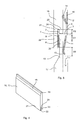
- Fig. 4 schematically shows a flat element in the form of an elongate, profiled panel 16, 17, for example a wood, plastic, stone, or Rockpanel® panel.
- Fig. 5 shows the fixing bracket of Figs 1 to 3 in a position in which it is used for mounting two similar such panels, more specifically an upper panel 16 and a lower panel 17.
- Fig. 5 thus shows a small part of a building façade or weather screen constructed by a number of similar panels, which are positioned in coplanarity in continuation of each other in the height direction of an underlying building structure 18 such that their front surfaces are substantially flush with each other.
- the panels of the façade including panels 16, 17, are generally, but not necessarily, similar to each other and form elongate panels positioned with their length direction extending horizontally, i.e. in the depth direction of the drawing plane of Fig. 4 .
- the panels each have substantially similar profile and cross-sectional shape throughout the length. As can be seen best in Fig. 4 , cf. the lower panel 17, the panels are each at a top portion 19 profiled such that a front surface of the panel tapers towards a rear surface to form a longitudinally extending key 20 that extends upwards. At a bottom portion 21 each of the panels further has two longitudinally extending projections 22, 23 that each projects downwards and extends in the length direction of the panel. These two projections take the form of a front projection 22 and a rear projection 23, respectively, forming a longitudinally extending groove 24 between them. In the present embodiment the front projection 22 is longer than the rear projection 23 such that in a mounted position the upper front fingers 6, 7 as well as the lower front fingers 8, 9 of the bracket are covered and hidden by the front projection 22.
- a number of fixing brackets similar to that of Figs 1 to 3 are secured in horizontal and vertical lines to the underlying building structure 18 to form an array of brackets (not shown).
- Each horizontal line of brackets (except the topmost and bottommost line) secures a bottom portion of an upper panel (in Fig. 4 bottom portion 21) as well as a top portion of a lower panel (in Fig. 4 top portion 19) to the underlying building structure 18.
- the fixing brackets are mounted at similar mutual vertical distances from each other, this distance being so that the panels can be released by shifting the panel upwards, until the rear projection of the bottom portion of the upper panel has moved beyond the upper front finger of the lower fixing bracket.
- the upper tongue 12 exerts a frontwards directed force (directed to the left in Fig. 5 ) on the rear surface of the bottom portion 21 of the upper panel 16 securing the rear projection 23 against the upper front finger 7 to thereby secure the bottom portion 21.
- the lower tongue 11 exerts a frontwards directed force on the rear surface of the top portion 19 of the lower panel 17 securing the key 20 against the lower front fingers 8, 9 to thereby secure the top portion 19.
- the tongues 11, 12 in the unloaded position, in which the panels are released, are shown in broken lines.
- the panel 16 can manually be shifted upwards until the rear projection 23 has moved beyond the upper front fingers 6, 7 of the fixing bracket.
- the panel 16 is thus shifted upwards until the rear projection 23 has moved beyond the upper front fingers 6, 7 of the fixing bracket.
- the shifting movement is eased by pushing the panel 16 backwards, thus pivoting also the tongues 12, 11 of respective upper and lower brackets in the backwards or rear direction.
- the upper tongue 12 of the lower bracket then automatically pushes or pivots the lower portion 21 outwards.
- the lower front fingers 8, 9 of the upper bracket are positioned at such distance from the building structure 18 that room R is provided for the upper portion of the flat element to be slightly rotated (clockwise in Fig. 5 ) after release of the bottom portion 21 so that the upper portion 19 of the panel 16 can be slid downwards and completely release the panel 16 from the fixing bracket.
- distance D1 is the distance in the up-down direction from an upper, distal end of the key 20 of the lower panel 17 to the central parts 2, 3 of the fixing bracket.
- Distance D2 is the distance in the up-down direction from a lower, proximal end of the key 20 to respective lower, distal ends of the lower front fingers 8, 9.
- the lower, proximal end of the key 20 is defined as that position from the top of the panel in which the key 20 changes its profile, i.e. in the present embodiment the position in which the panel's front surface changes direction.
- the front surface of the key 20 extends substantially linearly, preferably linearly in the up-down direction, in its entire length.
- Distance D3 is the distance in the up-down direction from an upper, distal end of the upper front fingers 6, 7 to a lower, distal end of the rear projection 23 of the upper panel 16.
- the bracket may be manufactured in ways different from being punched out of one plate, and that it may be manufactured from other materials than metal, such as moulded from plastic or aluminium.
- Figs 6 and 7 show a second embodiment of the fixing bracket according to the invention in which these features are varied.
- Fig. 6 shows a fixing bracket mounted on a building structure (in this case a wood bar or column) to secure a lower panel 17, and Fig. 7 shows this fixing bracket securing both the lower 17 and an upper panel 16, the view of Fig. 7 thus corresponding to that of Fig. 5 .
- this fixing bracket is in many ways, including function, similar to that of the first embodiment, and that in the following primarily differences from the first embodiment will be described. Thus, elements not described in the following are substantially similar to those of the previous embodiment.
- the panels used in this embodiment are of the type as illustrated in Fig. 4 , although the transition to the upper key 20 is curved in an initial portion instead of being straight.
- the central portion 1 comprises only a single part 2 that connects the front portion 4 and rear portion 5.
- the front portion 4 comprises only a single upper front finger 6 and lower front finger 8, respectively.
- the rear portion 5 comprises an upper rear finger 10.
- Each of the fingers 6, 8, 10 as well as the central part 2 are formed as flat, plane members or flanges.
- This embodiment of the fixing bracket may thus be manufactured for example by means of a metal or plastic casting process or by welding respective metal or plastic, one-piece front and rear portions 4, 5 to a one-piece central part 2.
- Each of these elements or even the whole fixing bracket may be manufactured for example as extruded aluminium.
- the lower front finger 8 is again longer than the upper front finger 6.
- the lower resilient tongue 11 curves from a straight portion that abuts the wall into an inclined portion that is bent frontwards, cf. Fig. 7 .
- the rear finger 10 comprises two holes 15 (not visible) for insertion of respective screws 25, of which the head is visible in Figs 6 and 7 , or like attachment means to mount the bracket to the underlying building structure 18.
- the screws 25 may be used as abutment for the upper panel 16 and may for this purpose be fitted with a suitable resilient cap or the like such as to provide a function similar to that of the upper resilient tongue as described above with reference to the first embodiment.
- Fig. 8 illustrates an example of use of two similar fixing brackets according to the third aspect of the invention.
- this embodiment of a fixing bracket is in many ways, including function and use, similar to that of the above two embodiments of the first aspect of the invention, and that in the following primarily differences from the first and second embodiments will be described. Elements not described in the following are substantially similar to the corresponding ones of the previous embodiments.
- the fixing bracket used in the embodiment of Fig. 8 is similar to that of the above first embodiment of the first aspect of the invention, except for the noteworthy fact that the lower front fingers 8, 9 (of which only finger 9 is visible in Fig. 8 ) are not longer than the upper front fingers 6, 7 (of which only finger 7 is visible in Fig. 8 ), instead it is somewhat shorter. However, it is understood that the lower front fingers 8, 9 may instead be longer than as well as be of the same length of the upper front fingers 6, 7.
- the upper front fingers 6, 7 of the fixing bracket are each so much longer than the rear projection 23 of the lower portion 21 of the applied flat elements 16, 17 that a bottom surface of the groove 24 of the bottom portion 21 rests on upper surfaces of the respective upper front fingers 6, 7.
- the upper portion 19 of a secured flat element 16, 17 is displaceable upwards with a distance to allow for the flat element 16, 17 to be released from the fixing brackets by shifting the flat element 16, 17 upwards, until the rear projection 23 of the bottom portion 21 has moved beyond the upper front fingers 6, 7 of the lower fixing bracket.
- a suitable distance between the two fixing brackets involves in this case that enough play is provided between the upper portion 19 of the lower flat element 16 and the central parts 2, 3 (of which only central part 3 is visible in Fig. 8 ), i.e. the distance between the upper portion 19 of the lower flat element 16 and the central parts 2, 3 is larger than the length of the rear projection 23 of the upper flat element 17.
- the flat element 16, 17 can then similar to the previous embodiments be released from the brackets with an upwards movement of translation. And again, simultaneously pushing the flat element 16, 17 backwards or rearwards accommodates the upwards movement of the flat element and thereby accommodates release of the flat element 16, 17.
- the fixing bracket may, as part of its rear portion, further comprise a lower rear finger that extends downwards from the upper rear finger.
- the lower tongue may be cut out from the lower rear finger similar to the upper tongue.
- screw holes may be provided for instance in part of the lower tongue (e.g. in the linear portion of the lower tongue of the embodiment of Figs 6 and 7 ) or in a lower rear finger.
- other attachment devices may form part of the fixing bracket, e.g. in the form of pins cut out from a metal rear portion of the bracket and bend backwards.
- finger as used in this specification is to be understood in its widest possible sense and is thus generally not meant to indicate any specific shape or form other than that each "finger” extends in a direction.
- the “fingers” may thus take any other suitable form than flanges or flat elements as long as they fulfil their inherent purpose, such as rod-shaped, whether circular-cylindrical or with another cross-sectional shape, such as rectangular, quadratic, or triangular.
Landscapes
- Engineering & Computer Science (AREA)
- Architecture (AREA)
- Civil Engineering (AREA)
- Structural Engineering (AREA)
- Finishing Walls (AREA)
Priority Applications (3)
| Application Number | Priority Date | Filing Date | Title |
|---|---|---|---|
| EP10189633.0A EP2447440B1 (en) | 2010-11-02 | 2010-11-02 | A fixing bracket, a system comprising such a fixing bracket, and use of a fixing bracket |
| PL10189633T PL2447440T3 (pl) | 2010-11-02 | 2010-11-02 | Wspornik mocujący, układ zawierający taki wspornik mocujący i zastosowanie wspornika mocującego |
| RU2011143591/03A RU2011143591A (ru) | 2010-11-02 | 2011-10-28 | Крепежная скоба, система с ее использованием и способ ее применения |
Applications Claiming Priority (1)
| Application Number | Priority Date | Filing Date | Title |
|---|---|---|---|
| EP10189633.0A EP2447440B1 (en) | 2010-11-02 | 2010-11-02 | A fixing bracket, a system comprising such a fixing bracket, and use of a fixing bracket |
Publications (2)
| Publication Number | Publication Date |
|---|---|
| EP2447440A1 EP2447440A1 (en) | 2012-05-02 |
| EP2447440B1 true EP2447440B1 (en) | 2014-12-17 |
Family
ID=43743717
Family Applications (1)
| Application Number | Title | Priority Date | Filing Date |
|---|---|---|---|
| EP10189633.0A Active EP2447440B1 (en) | 2010-11-02 | 2010-11-02 | A fixing bracket, a system comprising such a fixing bracket, and use of a fixing bracket |
Country Status (3)
| Country | Link |
|---|---|
| EP (1) | EP2447440B1 (pl) |
| PL (1) | PL2447440T3 (pl) |
| RU (1) | RU2011143591A (pl) |
Families Citing this family (9)
| Publication number | Priority date | Publication date | Assignee | Title |
|---|---|---|---|---|
| JP5358624B2 (ja) * | 2011-07-01 | 2013-12-04 | Wpcコーポレーション株式会社 | パネル用の固定金具 |
| RU2608369C2 (ru) * | 2014-03-31 | 2017-01-18 | Кей Эм Ю Ко., Лтд. | Стыковочная конструкция внешних стеновых материалов |
| JP6341502B2 (ja) * | 2014-05-21 | 2018-06-13 | 有限会社ユース北浦 | 外壁材取付金具 |
| AT515684B1 (de) * | 2014-10-14 | 2015-11-15 | Gaisbauer Günther | Fassadensystem und ein Halteteil zur Befestigung von zwei Sichtprofilen |
| DE102015100678A1 (de) * | 2015-01-19 | 2016-07-21 | White Hills Stones GmbH | Vorrichtung zum Befestigen von Verblendsteinen, insbesondere für den Fassadenbau, Trägerprofil und Verblendstein |
| JP6857978B2 (ja) * | 2016-07-12 | 2021-04-14 | ニチハ株式会社 | 外装材の取付具及び建物の外装構造 |
| JP6957173B2 (ja) * | 2017-03-15 | 2021-11-02 | ニチハ株式会社 | 取付具、取付具と防水材とのセット、壁構造、及び外装材の施工方法 |
| CN113047478B (zh) * | 2021-03-25 | 2022-07-12 | 青岛比佐迪家居有限公司 | 弹性挂件 |
| BE1029467B1 (nl) * | 2021-10-19 | 2023-01-06 | Houtmagazijn Verdonckt Nv | Montage clip voor lamellen en samenstelling van voorgaande |
Family Cites Families (8)
| Publication number | Priority date | Publication date | Assignee | Title |
|---|---|---|---|---|
| NO177801C (no) | 1993-04-16 | 1995-11-22 | Joergen Gether | Monteringsbeslag for fleksibel innfesting av elementer av naturstein til vertikale vegger |
| FR2734589B1 (fr) * | 1995-05-23 | 1997-07-18 | Euridep | Platine-entretoise de fixation pour la realisation de vetages dans le domaine du batiment, et vetages ainsi obtenus |
| DE19720016C2 (de) * | 1997-05-13 | 1999-04-01 | Gerhaher Max | Vorgehängte Fassadenkonstruktion |
| NL1013914C2 (nl) * | 1999-01-27 | 2000-08-08 | Houtprodukten Heuvelman B V | Werkwijze voor het aan een staande ondergrond bevestigen van een strook- of plaatvormig bekledingsmateriaal. |
| JP2001032500A (ja) | 1999-07-26 | 2001-02-06 | Onchi Seibyo Kk | サイディング外壁板留め付け金具 |
| JP2003268952A (ja) | 2002-03-15 | 2003-09-25 | Sekisui House Ltd | 外壁材取付金具 |
| DE10322346A1 (de) * | 2003-05-15 | 2004-12-09 | F. v. Müller Dachziegelwerke GmbH & Co. KG | Fassadenkonstruktion |
| JP4546301B2 (ja) | 2005-03-22 | 2010-09-15 | ニチハ株式会社 | 留め付け金具及び外壁施工構造 |
-
2010
- 2010-11-02 PL PL10189633T patent/PL2447440T3/pl unknown
- 2010-11-02 EP EP10189633.0A patent/EP2447440B1/en active Active
-
2011
- 2011-10-28 RU RU2011143591/03A patent/RU2011143591A/ru not_active Application Discontinuation
Also Published As
| Publication number | Publication date |
|---|---|
| EP2447440A1 (en) | 2012-05-02 |
| PL2447440T3 (pl) | 2015-05-29 |
| RU2011143591A (ru) | 2013-05-10 |
Similar Documents
| Publication | Publication Date | Title |
|---|---|---|
| EP2447440A1 (en) | A fixing bracket, a system comprising such a fixing bracket, and use of a fixing bracket | |
| EP2230365B1 (en) | Flooring system | |
| US7726088B2 (en) | Flooring system | |
| EP1695744B1 (en) | Mounting structure for sprinklers | |
| US8024904B2 (en) | Panel and fastening system for such panel | |
| CN104350219B (zh) | 格栅龙骨的周边装饰夹子 | |
| US20070234670A1 (en) | Fastener for grooved or slotted decking members | |
| US8434738B1 (en) | Flooring installation tool | |
| JP4796578B2 (ja) | 受け具 | |
| JP2008206751A (ja) | 棚板支持部材及びそれを使用した棚板支持構造 | |
| JP3140518U (ja) | 巾木スターター及びそれを用いた施工構造 | |
| JP4472545B2 (ja) | タイル取付け構造 | |
| JP2009174153A (ja) | デッキ材固定金具およびデッキ材固定方法 | |
| JP3412758B2 (ja) | ブックサポート付き書架 | |
| JP2005140330A (ja) | 連結素子、およびそれを用いる取付け組立品 | |
| JP3146398U (ja) | 巾木スターター及びそれを用いた施工構造 | |
| JP4133689B2 (ja) | ロッキング外壁パネル | |
| JP2004027644A (ja) | 役物の固定金具 | |
| JP4590251B2 (ja) | 部材の固定構造 | |
| JP5991811B2 (ja) | 外装材取付金具 | |
| KR200350818Y1 (ko) | 문틀설치용 고정구의 개량구조 | |
| JP7556763B2 (ja) | 耐風補強部材 | |
| JP4641822B2 (ja) | 板材支持具 | |
| KR20200105058A (ko) | 벽체 배수판용 클립바 고정클립 | |
| JP2008045388A (ja) | デッキ材の取り付け構造 |
Legal Events
| Date | Code | Title | Description |
|---|---|---|---|
| PUAI | Public reference made under article 153(3) epc to a published international application that has entered the european phase |
Free format text: ORIGINAL CODE: 0009012 |
|
| AK | Designated contracting states |
Kind code of ref document: A1 Designated state(s): AL AT BE BG CH CY CZ DE DK EE ES FI FR GB GR HR HU IE IS IT LI LT LU LV MC MK MT NL NO PL PT RO RS SE SI SK SM TR |
|
| AX | Request for extension of the european patent |
Extension state: BA ME |
|
| 17P | Request for examination filed |
Effective date: 20121011 |
|
| GRAP | Despatch of communication of intention to grant a patent |
Free format text: ORIGINAL CODE: EPIDOSNIGR1 |
|
| INTG | Intention to grant announced |
Effective date: 20140626 |
|
| GRAS | Grant fee paid |
Free format text: ORIGINAL CODE: EPIDOSNIGR3 |
|
| GRAA | (expected) grant |
Free format text: ORIGINAL CODE: 0009210 |
|
| AK | Designated contracting states |
Kind code of ref document: B1 Designated state(s): AL AT BE BG CH CY CZ DE DK EE ES FI FR GB GR HR HU IE IS IT LI LT LU LV MC MK MT NL NO PL PT RO RS SE SI SK SM TR |
|
| REG | Reference to a national code |
Ref country code: GB Ref legal event code: FG4D |
|
| REG | Reference to a national code |
Ref country code: CH Ref legal event code: EP |
|
| REG | Reference to a national code |
Ref country code: IE Ref legal event code: FG4D |
|
| REG | Reference to a national code |
Ref country code: AT Ref legal event code: REF Ref document number: 702063 Country of ref document: AT Kind code of ref document: T Effective date: 20150115 |
|
| REG | Reference to a national code |
Ref country code: DE Ref legal event code: R096 Ref document number: 602010021010 Country of ref document: DE Effective date: 20150129 |
|
| REG | Reference to a national code |
Ref country code: NL Ref legal event code: T3 |
|
| PG25 | Lapsed in a contracting state [announced via postgrant information from national office to epo] |
Ref country code: FI Free format text: LAPSE BECAUSE OF FAILURE TO SUBMIT A TRANSLATION OF THE DESCRIPTION OR TO PAY THE FEE WITHIN THE PRESCRIBED TIME-LIMIT Effective date: 20141217 Ref country code: LT Free format text: LAPSE BECAUSE OF FAILURE TO SUBMIT A TRANSLATION OF THE DESCRIPTION OR TO PAY THE FEE WITHIN THE PRESCRIBED TIME-LIMIT Effective date: 20141217 Ref country code: NO Free format text: LAPSE BECAUSE OF FAILURE TO SUBMIT A TRANSLATION OF THE DESCRIPTION OR TO PAY THE FEE WITHIN THE PRESCRIBED TIME-LIMIT Effective date: 20150317 |
|
| REG | Reference to a national code |
Ref country code: LT Ref legal event code: MG4D |
|
| PG25 | Lapsed in a contracting state [announced via postgrant information from national office to epo] |
Ref country code: RS Free format text: LAPSE BECAUSE OF FAILURE TO SUBMIT A TRANSLATION OF THE DESCRIPTION OR TO PAY THE FEE WITHIN THE PRESCRIBED TIME-LIMIT Effective date: 20141217 Ref country code: LV Free format text: LAPSE BECAUSE OF FAILURE TO SUBMIT A TRANSLATION OF THE DESCRIPTION OR TO PAY THE FEE WITHIN THE PRESCRIBED TIME-LIMIT Effective date: 20141217 Ref country code: GR Free format text: LAPSE BECAUSE OF FAILURE TO SUBMIT A TRANSLATION OF THE DESCRIPTION OR TO PAY THE FEE WITHIN THE PRESCRIBED TIME-LIMIT Effective date: 20150318 Ref country code: SE Free format text: LAPSE BECAUSE OF FAILURE TO SUBMIT A TRANSLATION OF THE DESCRIPTION OR TO PAY THE FEE WITHIN THE PRESCRIBED TIME-LIMIT Effective date: 20141217 Ref country code: HR Free format text: LAPSE BECAUSE OF FAILURE TO SUBMIT A TRANSLATION OF THE DESCRIPTION OR TO PAY THE FEE WITHIN THE PRESCRIBED TIME-LIMIT Effective date: 20141217 |
|
| REG | Reference to a national code |
Ref country code: PL Ref legal event code: T3 |
|
| PG25 | Lapsed in a contracting state [announced via postgrant information from national office to epo] |
Ref country code: ES Free format text: LAPSE BECAUSE OF FAILURE TO SUBMIT A TRANSLATION OF THE DESCRIPTION OR TO PAY THE FEE WITHIN THE PRESCRIBED TIME-LIMIT Effective date: 20141217 Ref country code: RO Free format text: LAPSE BECAUSE OF FAILURE TO SUBMIT A TRANSLATION OF THE DESCRIPTION OR TO PAY THE FEE WITHIN THE PRESCRIBED TIME-LIMIT Effective date: 20141217 Ref country code: CZ Free format text: LAPSE BECAUSE OF FAILURE TO SUBMIT A TRANSLATION OF THE DESCRIPTION OR TO PAY THE FEE WITHIN THE PRESCRIBED TIME-LIMIT Effective date: 20141217 Ref country code: SK Free format text: LAPSE BECAUSE OF FAILURE TO SUBMIT A TRANSLATION OF THE DESCRIPTION OR TO PAY THE FEE WITHIN THE PRESCRIBED TIME-LIMIT Effective date: 20141217 Ref country code: EE Free format text: LAPSE BECAUSE OF FAILURE TO SUBMIT A TRANSLATION OF THE DESCRIPTION OR TO PAY THE FEE WITHIN THE PRESCRIBED TIME-LIMIT Effective date: 20141217 |
|
| PG25 | Lapsed in a contracting state [announced via postgrant information from national office to epo] |
Ref country code: IS Free format text: LAPSE BECAUSE OF FAILURE TO SUBMIT A TRANSLATION OF THE DESCRIPTION OR TO PAY THE FEE WITHIN THE PRESCRIBED TIME-LIMIT Effective date: 20150417 |
|
| REG | Reference to a national code |
Ref country code: DE Ref legal event code: R097 Ref document number: 602010021010 Country of ref document: DE |
|
| PLBE | No opposition filed within time limit |
Free format text: ORIGINAL CODE: 0009261 |
|
| REG | Reference to a national code |
Ref country code: FR Ref legal event code: PLFP Year of fee payment: 6 |
|
| STAA | Information on the status of an ep patent application or granted ep patent |
Free format text: STATUS: NO OPPOSITION FILED WITHIN TIME LIMIT |
|
| PG25 | Lapsed in a contracting state [announced via postgrant information from national office to epo] |
Ref country code: DK Free format text: LAPSE BECAUSE OF FAILURE TO SUBMIT A TRANSLATION OF THE DESCRIPTION OR TO PAY THE FEE WITHIN THE PRESCRIBED TIME-LIMIT Effective date: 20141217 |
|
| 26N | No opposition filed |
Effective date: 20150918 |
|
| PG25 | Lapsed in a contracting state [announced via postgrant information from national office to epo] |
Ref country code: IT Free format text: LAPSE BECAUSE OF FAILURE TO SUBMIT A TRANSLATION OF THE DESCRIPTION OR TO PAY THE FEE WITHIN THE PRESCRIBED TIME-LIMIT Effective date: 20141217 |
|
| PG25 | Lapsed in a contracting state [announced via postgrant information from national office to epo] |
Ref country code: SI Free format text: LAPSE BECAUSE OF FAILURE TO SUBMIT A TRANSLATION OF THE DESCRIPTION OR TO PAY THE FEE WITHIN THE PRESCRIBED TIME-LIMIT Effective date: 20141217 |
|
| REG | Reference to a national code |
Ref country code: AT Ref legal event code: UEP Ref document number: 702063 Country of ref document: AT Kind code of ref document: T Effective date: 20141217 |
|
| PG25 | Lapsed in a contracting state [announced via postgrant information from national office to epo] |
Ref country code: LU Free format text: LAPSE BECAUSE OF FAILURE TO SUBMIT A TRANSLATION OF THE DESCRIPTION OR TO PAY THE FEE WITHIN THE PRESCRIBED TIME-LIMIT Effective date: 20151102 Ref country code: MC Free format text: LAPSE BECAUSE OF FAILURE TO SUBMIT A TRANSLATION OF THE DESCRIPTION OR TO PAY THE FEE WITHIN THE PRESCRIBED TIME-LIMIT Effective date: 20141217 |
|
| REG | Reference to a national code |
Ref country code: CH Ref legal event code: PL |
|
| PG25 | Lapsed in a contracting state [announced via postgrant information from national office to epo] |
Ref country code: CH Free format text: LAPSE BECAUSE OF NON-PAYMENT OF DUE FEES Effective date: 20151130 Ref country code: LI Free format text: LAPSE BECAUSE OF NON-PAYMENT OF DUE FEES Effective date: 20151130 |
|
| REG | Reference to a national code |
Ref country code: IE Ref legal event code: MM4A |
|
| REG | Reference to a national code |
Ref country code: FR Ref legal event code: PLFP Year of fee payment: 7 |
|
| PG25 | Lapsed in a contracting state [announced via postgrant information from national office to epo] |
Ref country code: IE Free format text: LAPSE BECAUSE OF NON-PAYMENT OF DUE FEES Effective date: 20151102 |
|
| PG25 | Lapsed in a contracting state [announced via postgrant information from national office to epo] |
Ref country code: BG Free format text: LAPSE BECAUSE OF FAILURE TO SUBMIT A TRANSLATION OF THE DESCRIPTION OR TO PAY THE FEE WITHIN THE PRESCRIBED TIME-LIMIT Effective date: 20141217 Ref country code: SM Free format text: LAPSE BECAUSE OF FAILURE TO SUBMIT A TRANSLATION OF THE DESCRIPTION OR TO PAY THE FEE WITHIN THE PRESCRIBED TIME-LIMIT Effective date: 20141217 Ref country code: HU Free format text: LAPSE BECAUSE OF FAILURE TO SUBMIT A TRANSLATION OF THE DESCRIPTION OR TO PAY THE FEE WITHIN THE PRESCRIBED TIME-LIMIT; INVALID AB INITIO Effective date: 20101102 |
|
| PG25 | Lapsed in a contracting state [announced via postgrant information from national office to epo] |
Ref country code: CY Free format text: LAPSE BECAUSE OF FAILURE TO SUBMIT A TRANSLATION OF THE DESCRIPTION OR TO PAY THE FEE WITHIN THE PRESCRIBED TIME-LIMIT Effective date: 20141217 |
|
| PG25 | Lapsed in a contracting state [announced via postgrant information from national office to epo] |
Ref country code: TR Free format text: LAPSE BECAUSE OF FAILURE TO SUBMIT A TRANSLATION OF THE DESCRIPTION OR TO PAY THE FEE WITHIN THE PRESCRIBED TIME-LIMIT Effective date: 20141217 Ref country code: MT Free format text: LAPSE BECAUSE OF FAILURE TO SUBMIT A TRANSLATION OF THE DESCRIPTION OR TO PAY THE FEE WITHIN THE PRESCRIBED TIME-LIMIT Effective date: 20141217 |
|
| REG | Reference to a national code |
Ref country code: FR Ref legal event code: PLFP Year of fee payment: 8 |
|
| PG25 | Lapsed in a contracting state [announced via postgrant information from national office to epo] |
Ref country code: MK Free format text: LAPSE BECAUSE OF FAILURE TO SUBMIT A TRANSLATION OF THE DESCRIPTION OR TO PAY THE FEE WITHIN THE PRESCRIBED TIME-LIMIT Effective date: 20141217 |
|
| PG25 | Lapsed in a contracting state [announced via postgrant information from national office to epo] |
Ref country code: PT Free format text: LAPSE BECAUSE OF FAILURE TO SUBMIT A TRANSLATION OF THE DESCRIPTION OR TO PAY THE FEE WITHIN THE PRESCRIBED TIME-LIMIT Effective date: 20141217 |
|
| PG25 | Lapsed in a contracting state [announced via postgrant information from national office to epo] |
Ref country code: AL Free format text: LAPSE BECAUSE OF FAILURE TO SUBMIT A TRANSLATION OF THE DESCRIPTION OR TO PAY THE FEE WITHIN THE PRESCRIBED TIME-LIMIT Effective date: 20141217 |
|
| REG | Reference to a national code |
Ref country code: DE Ref legal event code: R082 Ref document number: 602010021010 Country of ref document: DE Representative=s name: KILBURN & STRODE LLP, NL |
|
| REG | Reference to a national code |
Ref country code: NL Ref legal event code: HC Owner name: ROCKWOOL A/S; DK Free format text: DETAILS ASSIGNMENT: CHANGE OF OWNER(S), CHANGE OF OWNER(S) NAME; FORMER OWNER NAME: ROCKWOOL INTERNATIONAL A/S Effective date: 20230728 |
|
| REG | Reference to a national code |
Ref country code: DE Ref legal event code: R081 Ref document number: 602010021010 Country of ref document: DE Owner name: ROCKWOOL A/S, DK Free format text: FORMER OWNER: ROCKWOOL INTERNATIONAL A/S, HEDEHUSENE, DK Ref country code: DE Ref legal event code: R082 Ref document number: 602010021010 Country of ref document: DE |
|
| REG | Reference to a national code |
Ref country code: AT Ref legal event code: HC Ref document number: 702063 Country of ref document: AT Kind code of ref document: T Owner name: ROCKWOOL A/S, DK Effective date: 20230929 |
|
| REG | Reference to a national code |
Ref country code: BE Ref legal event code: PD Owner name: ROCKWOOL INTERNATIONAL A/S; DK Free format text: DETAILS ASSIGNMENT: CHANGE OF OWNER(S), OTHER; FORMER OWNER NAME: ROCKWOOL INTERNATIONAL A/S Effective date: 20241212 Ref country code: BE Ref legal event code: HC Owner name: ROCKWOOL A/S; DK Free format text: DETAILS ASSIGNMENT: CHANGE OF OWNER(S), CHANGE OF OWNER(S) NAME; FORMER OWNER NAME: ROCKWOOL INTERNATIONAL A/S Effective date: 20241212 |
|
| PGFP | Annual fee paid to national office [announced via postgrant information from national office to epo] |
Ref country code: NL Payment date: 20251126 Year of fee payment: 16 |
|
| PGFP | Annual fee paid to national office [announced via postgrant information from national office to epo] |
Ref country code: DE Payment date: 20251128 Year of fee payment: 16 |
|
| PGFP | Annual fee paid to national office [announced via postgrant information from national office to epo] |
Ref country code: GB Payment date: 20251127 Year of fee payment: 16 |
|
| PGFP | Annual fee paid to national office [announced via postgrant information from national office to epo] |
Ref country code: AT Payment date: 20251128 Year of fee payment: 16 |
|
| PGFP | Annual fee paid to national office [announced via postgrant information from national office to epo] |
Ref country code: FR Payment date: 20251125 Year of fee payment: 16 |
|
| PGFP | Annual fee paid to national office [announced via postgrant information from national office to epo] |
Ref country code: BE Payment date: 20251127 Year of fee payment: 16 |
|
| PGFP | Annual fee paid to national office [announced via postgrant information from national office to epo] |
Ref country code: PL Payment date: 20251021 Year of fee payment: 16 |