EP2444643A2 - Direkteingespritzter motor und steuereinrichtung dafür - Google Patents
Direkteingespritzter motor und steuereinrichtung dafür Download PDFInfo
- Publication number
- EP2444643A2 EP2444643A2 EP11185964A EP11185964A EP2444643A2 EP 2444643 A2 EP2444643 A2 EP 2444643A2 EP 11185964 A EP11185964 A EP 11185964A EP 11185964 A EP11185964 A EP 11185964A EP 2444643 A2 EP2444643 A2 EP 2444643A2
- Authority
- EP
- European Patent Office
- Prior art keywords
- fuel
- piston
- engine
- mixed gas
- combustion chamber
- Prior art date
- Legal status (The legal status is an assumption and is not a legal conclusion. Google has not performed a legal analysis and makes no representation as to the accuracy of the status listed.)
- Withdrawn
Links
- 238000002347 injection Methods 0.000 title claims abstract description 49
- 239000007924 injection Substances 0.000 title claims abstract description 49
- 239000000446 fuel Substances 0.000 claims abstract description 91
- 238000002485 combustion reaction Methods 0.000 claims abstract description 52
- 230000006835 compression Effects 0.000 claims abstract description 15
- 238000007906 compression Methods 0.000 claims abstract description 15
- 239000003054 catalyst Substances 0.000 claims description 13
- 239000007921 spray Substances 0.000 claims description 12
- 230000000630 rising effect Effects 0.000 abstract description 16
- 230000007423 decrease Effects 0.000 abstract description 8
- 239000013618 particulate matter Substances 0.000 abstract description 7
- 230000003247 decreasing effect Effects 0.000 abstract description 4
- 238000013517 stratification Methods 0.000 abstract description 4
- 230000001629 suppression Effects 0.000 abstract 1
- 230000004913 activation Effects 0.000 description 4
- 230000003111 delayed effect Effects 0.000 description 3
- 239000012141 concentrate Substances 0.000 description 2
- 230000035515 penetration Effects 0.000 description 2
- 238000011144 upstream manufacturing Methods 0.000 description 2
- XLYOFNOQVPJJNP-UHFFFAOYSA-N water Substances O XLYOFNOQVPJJNP-UHFFFAOYSA-N 0.000 description 2
- 230000003213 activating effect Effects 0.000 description 1
- 239000000498 cooling water Substances 0.000 description 1
- 238000009792 diffusion process Methods 0.000 description 1
- 239000007788 liquid Substances 0.000 description 1
- 238000000034 method Methods 0.000 description 1
- 238000012986 modification Methods 0.000 description 1
- 230000004048 modification Effects 0.000 description 1
- 230000001105 regulatory effect Effects 0.000 description 1
- 239000000126 substance Substances 0.000 description 1
Images


Classifications
-
- F—MECHANICAL ENGINEERING; LIGHTING; HEATING; WEAPONS; BLASTING
- F02—COMBUSTION ENGINES; HOT-GAS OR COMBUSTION-PRODUCT ENGINE PLANTS
- F02D—CONTROLLING COMBUSTION ENGINES
- F02D41/00—Electrical control of supply of combustible mixture or its constituents
- F02D41/30—Controlling fuel injection
- F02D41/38—Controlling fuel injection of the high pressure type
- F02D41/40—Controlling fuel injection of the high pressure type with means for controlling injection timing or duration
- F02D41/402—Multiple injections
-
- F—MECHANICAL ENGINEERING; LIGHTING; HEATING; WEAPONS; BLASTING
- F02—COMBUSTION ENGINES; HOT-GAS OR COMBUSTION-PRODUCT ENGINE PLANTS
- F02D—CONTROLLING COMBUSTION ENGINES
- F02D41/00—Electrical control of supply of combustible mixture or its constituents
- F02D41/30—Controlling fuel injection
- F02D41/3011—Controlling fuel injection according to or using specific or several modes of combustion
- F02D41/3017—Controlling fuel injection according to or using specific or several modes of combustion characterised by the mode(s) being used
- F02D41/3023—Controlling fuel injection according to or using specific or several modes of combustion characterised by the mode(s) being used a mode being the stratified charge spark-ignited mode
-
- F—MECHANICAL ENGINEERING; LIGHTING; HEATING; WEAPONS; BLASTING
- F02—COMBUSTION ENGINES; HOT-GAS OR COMBUSTION-PRODUCT ENGINE PLANTS
- F02D—CONTROLLING COMBUSTION ENGINES
- F02D41/00—Electrical control of supply of combustible mixture or its constituents
- F02D41/30—Controlling fuel injection
- F02D41/38—Controlling fuel injection of the high pressure type
- F02D41/40—Controlling fuel injection of the high pressure type with means for controlling injection timing or duration
- F02D41/401—Controlling injection timing
-
- F—MECHANICAL ENGINEERING; LIGHTING; HEATING; WEAPONS; BLASTING
- F02—COMBUSTION ENGINES; HOT-GAS OR COMBUSTION-PRODUCT ENGINE PLANTS
- F02D—CONTROLLING COMBUSTION ENGINES
- F02D41/00—Electrical control of supply of combustible mixture or its constituents
- F02D41/0002—Controlling intake air
- F02D2041/001—Controlling intake air for engines with variable valve actuation
-
- F—MECHANICAL ENGINEERING; LIGHTING; HEATING; WEAPONS; BLASTING
- F02—COMBUSTION ENGINES; HOT-GAS OR COMBUSTION-PRODUCT ENGINE PLANTS
- F02D—CONTROLLING COMBUSTION ENGINES
- F02D2200/00—Input parameters for engine control
- F02D2200/02—Input parameters for engine control the parameters being related to the engine
- F02D2200/08—Exhaust gas treatment apparatus parameters
- F02D2200/0802—Temperature of the exhaust gas treatment apparatus
-
- F—MECHANICAL ENGINEERING; LIGHTING; HEATING; WEAPONS; BLASTING
- F02—COMBUSTION ENGINES; HOT-GAS OR COMBUSTION-PRODUCT ENGINE PLANTS
- F02D—CONTROLLING COMBUSTION ENGINES
- F02D41/00—Electrical control of supply of combustible mixture or its constituents
- F02D41/02—Circuit arrangements for generating control signals
- F02D41/04—Introducing corrections for particular operating conditions
- F02D41/047—Taking into account fuel evaporation or wall wetting
-
- F—MECHANICAL ENGINEERING; LIGHTING; HEATING; WEAPONS; BLASTING
- F02—COMBUSTION ENGINES; HOT-GAS OR COMBUSTION-PRODUCT ENGINE PLANTS
- F02D—CONTROLLING COMBUSTION ENGINES
- F02D41/00—Electrical control of supply of combustible mixture or its constituents
- F02D41/02—Circuit arrangements for generating control signals
- F02D41/04—Introducing corrections for particular operating conditions
- F02D41/06—Introducing corrections for particular operating conditions for engine starting or warming up
- F02D41/062—Introducing corrections for particular operating conditions for engine starting or warming up for starting
- F02D41/064—Introducing corrections for particular operating conditions for engine starting or warming up for starting at cold start
-
- Y—GENERAL TAGGING OF NEW TECHNOLOGICAL DEVELOPMENTS; GENERAL TAGGING OF CROSS-SECTIONAL TECHNOLOGIES SPANNING OVER SEVERAL SECTIONS OF THE IPC; TECHNICAL SUBJECTS COVERED BY FORMER USPC CROSS-REFERENCE ART COLLECTIONS [XRACs] AND DIGESTS
- Y02—TECHNOLOGIES OR APPLICATIONS FOR MITIGATION OR ADAPTATION AGAINST CLIMATE CHANGE
- Y02T—CLIMATE CHANGE MITIGATION TECHNOLOGIES RELATED TO TRANSPORTATION
- Y02T10/00—Road transport of goods or passengers
- Y02T10/10—Internal combustion engine [ICE] based vehicles
- Y02T10/40—Engine management systems
Definitions
- the present invention relates to a cylinder injection engine and a control device for the engine.
- an ignition retard control technique for early activating the catalyst, an ignition retard control technique is used in which an ignition timing is retarded from a top dead point to raise a temperature of the exhaust gas, and for stably combusting when the ignition is retarded, it is necessary to form the layer of the mixed gas around the ignition plug.
- the fuel is injected in a later stage of the compression stroke, to collect the mixed gas around the ignition plug by a configuration of a piston or a penetration force of the spray of the fuel.
- a distance from a tip of a fuel injection valve to the piston is short, and a large amount of the fuel is adhered on the surface of the piston.
- diffusion combustion occurs at a place where a fuel liquid film is formed to noticeably increases a discharged amount of a particulate matter (PM).
- PM particulate matter
- An object of the present invention is to achieve both of the decrease of a fuel adhered on a piston during fast idling of cold start and the stratification of a mixed gas onto an ignition plug.
- a fuel injection timing is set to be a timing between a middle stage of a suction stroke and the vicinity of a piston bottom dead center.
- a mechanism which can vary an opening/closing timing of a suction valve is provided to set the closing timing of the suction valve to a middle stage of a compression stroke in which a piston moving speed becomes maximum, so as to generate a rising flow by flowing the mixed gas from combustion chamber to a suction pipe according to the piston rising in the compression stroke, and means is further provided in which the raised mixed gas is stratified around the ignition plug.
- a spray specification may be determined so that an intersection point between a fuel spray centroidal line and a piston surface at the piston bottom dead center is on an exhaust side closer than a center line of the ignition plug.
- the fuel injected in the vicinity of the piston bottom dead center forms the mixed gas on the exhaust side of the piston surface, and hence it becomes easy to stratify the mixed gas raised by the rising flow onto the ignition plug.
- a shape of the piston may be determined by providing a depression on an exhaust side of a piston surface so that a suction-side edge of the depression is disposed under the ignition plug. A flowing air and the mixed gas rise from the edge of the depression so as to suppress cycle fluctuations, which enables more stable combustion when ignition is retarded.
- the number of times of the fuel injection may be divided into a plurality of times, and a first fuel injection timing may be set to a timing after the suction valve opens. If all the fuel is stratified around the ignition plug, it is feared that the fuel excessively concentrates, to generate a PM. Therefore, when the fuel is divided and injected at the plurality of times, the fuel which is stratified around the ignition plug can be decreased, and the PM generation can be suppressed.
- the operation of the above first aspect may be performed in a state where a catalyst is inactive.
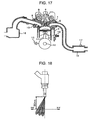
- FIG. 17 A constitution of a cylinder injection engine in first to third embodiments is shown in Fig. 17 .
- a combustion chamber is formed by a cylinder head 1, a cylinder block 2, and a piston 3 inserted into the cylinder block, and an ignition plug 4 is provided in an upper portion of the center of the combustion chamber.
- a suction pipe 5 and an exhaust pipe 6 open, respectively, and a suction valve 7 and an exhaust valve 8 for opening and closing open portions of the pipes are provided.
- the exhaust valve and the suction valve have a usually used cam operation system, and the exhaust valve closes at a top dead point and the suction valve opens at the top dead point.
- An opening period of the suction valve is 220 deg.
- a variable valve 9 which can vary a phase of the suction valve. As shown in Fig.
- an opening timing is 0 degATDC and a closing timing is 220 degATDC.
- the opening timing can be 60 degATDC
- the closing timing can be 280 degATDC.
- a fuel injection valve 10 On a suction side of the combustion chamber, a fuel injection valve 10 is provided so that the valve can directly inject a fuel into the combustion chamber.
- the fuel injection valve is a multi-hole injector from which the fuel is injected through six injection holes, respectively, as shown in Fig. 18 , and the sprayed fuel has a sectional configuration, as shown in Fig. 19 , which is 30 mm under a tip of each injection hole.
- the present spray has the configuration which does not hit the suction valve, even when the fuel is injected on conditions that the suction valve is lifted to the maximum.
- the fuel injection valve is installed so that the ignition plug has a direction on the right side of the spray in Fig. 19 . In a state where the fuel injection valve is attached to the engine, as shown in Fig.
- an intersection point 21 between a spray centroidal line 20 and a piston bottom dead center is positioned on an exhaust side closer than an ignition plug center line 22.
- the injected fuel reaches the exhaust side of the piston.
- a pressure of the fuel is raised by a high-pressure fuel pump (not shown) to inject the fuel.
- the piston is connected to a crank shaft 12 via a connection rod 11, and an engine rotation number can be calculated by a crank angle sensor 13.
- a water temperature sensor 14 is attached, and a temperature of engine cooling water can be calculated.
- a collector 15 On an upstream side of the suction pipe is connected a collector 15, and an air flow sensor and a throttle valve are provided on an upstream side of the collector, although not shown. An amount of air to be sucked into the combustion chamber can be adjusted by opening and closing the throttle valve.
- the present embodiment is a 4-cylinder engine including each cylinder of 500 cc and having a compression ratio of 10, and the air is distributed to the respective cylinders through the collector.
- an air-fuel ratio sensor not shown and the like, in addition to a three way catalyst 16 and a catalyst temperature sensor 17.
- An engine control unit (not shown) is connected so that the unit can receive sensor signals and control a device, and in an ROM of an ECU, set values of various devices in accordance with the engine rotation number, water temperature, catalyst temperature and air-fuel ratio are recorded as map data.
- a first embodiment of the present invention will be described with reference to Fig. 1 to Fig. 5 .
- an engine rotation number is 600 r/min or more and a catalyst temperature is lower than a temperature at which the catalyst becomes active
- the start is judged as fast idling, to start ignition retard control.
- An ignition timing is set to 16 degATDC after a compression top dead point, and a variable valve operates to execute control so that a suction valve closing timing becomes 280 degATDC.
- a desired fuel amount is calculated so that an engine torque becomes a desirable value with respect to the ignition timing and the suction valve closing timing.
- a desired intake air amount is calculated so that an air-fuel ratio becomes 16 during the fast idling, and a throttle open degree is determined so that the intake air amount becomes a desired value, whereby a throttle valve is controlled.
- the engine rotation number is 1200 r/min
- a shown average effective pressure is 1.8 bar
- a filling efficiency is 47%. From these conditions, the throttle open degree is determined, and the throttle valve is controlled.
- a pulse width corresponding to a fuel pressure is calculated in accordance with injection characteristics of a fuel injection valve.
- the present embodiment is a system in which a fuel is injected once in a cycle.
- a fuel pressure is 12 MPa, and an injection pulse width is 1.8 ms.
- a fuel injection timing is set to a range of 160 degATDC to 190 degATDC, while a piston bottom dead center is 180 degATDC. In the present embodiment, the fuel injection timing is set to 160 degATDC.
- a piston moves away from the spray of an injected fuel, and hence a broad injectable region can be obtained.
- a relation between an opening period of a suction valve and an injection timing is shown in Fig. 20 .
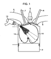
- FIG. 1 shows a condition in a combustion chamber at 173 degATDC immediately after the fuel is injected.
- the piston lowers so that the combustion chamber has a negative pressure therein.
- the suction valve opens, air is sucked into the combustion chamber through an opening of the suction valve.
- the air flows into the combustion chamber through the whole periphery of the suction valve.
- a flowing air which flows into an exhaust side through the suction valve is an air flow 18, and a flowing air which flows into a suction side is an air flow 19.
- the air flow 18 collides with the air flow 19 near the center of the combustion chamber above the surface of the piston, and changes to a rising flow there.
- the injected fuel flows in an injection direction.
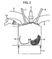
- Fig. 2 shows a condition in the combustion chamber at the piston bottom dead center.
- the injected fuel reaches the piston surface on the exhaust side, and evaporates to form a mixed gas.
- a distance from a tip of the fuel injection valve to a piston surface is long, and hence the fuel adhered on the piston becomes minimum.
- a piston speed becomes slow, and hence flow velocities of the air flows 18 and 19 lower.
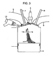
- Fig. 3 shows a condition in the combustion chamber at 210 degATDC in an early stage of the compression stroke.
- the air and the mixed gas are pushed upwards. Since the suction valve is open, the air flows from the combustion chamber to a suction pipe, and the flow velocities of the air flows 18 and 19 increase.
- the air flows 18 and 19 become a rising flow from the piston surface toward the suction pipe, and by this rising flow, the mixed gas is transported toward the suction valve.
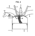
- Fig. 4 shows a condition in the combustion chamber at 280 degATDC which is a suction valve closing timing.
- the mixed gas is transported to the suction valve by the air flows 18 and 19.
- the suction valve closes, and hence an outlet is eliminated.
- the air flow 18 becomes a flow from an ignition plug toward the exhaust side
- the air flow 19 becomes a flow from the ignition plug toward the suction side, whereby two swirls are generated in the combustion chamber.
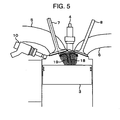
- Fig. 5 shows a condition in the combustion chamber at 330 degATDC in a later stage of the compression stroke.
- the suction valve closes to eliminate a factor for generating the flowing air, and hence the air flows 18 and 19 decay, and the mixed gas is suspended around the ignition plug.
- the flowing air further decays, and the mixed gas is suspended around the ignition plug. Therefore, even when the ignition timing is delayed to 16 degATDC, the mixed gas is constantly present around the ignition plug, which enables ignition.
- the suction valve closing timing is delayed to generate the rising flow.
- the mixed gas is transported to the ignition plug, whereby it is possible to maintain the mixed gas around the plug even when the ignition is retarded. It is possible to achieve both of the decrease of the fuel adhesion to the piston and the early activation of the catalyst.
- the mixed gas is disposed on the exhaust side at the piston bottom dead center, whereby when the mixed gas rises, the mixed gas easily reaches the ignition plug.
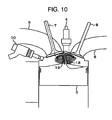
- a second embodiment will be described with reference to Fig. 6 to Fig. 10 .
- the embodiment is different from the first embodiment in that a depression is provided on an exhaust side of a piston surface.
- a suction-side edge of this depression has such a shape as to be positioned under an ignition plug.
- Fig. 6 shows a condition in a combustion chamber at 173 degATDC immediately after the fuel is injected.
- the condition is different from Fig. 1 of the first embodiment in that when an air flow 18 on the exhaust side reaches the piston, a direction of the air flow is changed to an upward direction at the edge of the depression.
- Fig. 7 shows a condition in the combustion chamber at a piston bottom dead center.
- Fig. 8 shows a condition in the combustion chamber at 210 degATDC in an early stage of a compression stroke. At the edge of the depression, the air flow 18 rises, and the mixed gas also flows toward a suction valve by the rising flow.
- Fig. 9 shows a condition in the combustion chamber at 280 degATDC which is a suction valve closing timing.
- Fig. 10 shows a condition in the combustion chamber at 330 degATDC in a later stage of the compression stroke.
- the rising positions of the air flow and the mixed gas can be regulated, and the cycle fluctuations can be suppressed. Moreover, when the suction-side edge of the depression is disposed under the ignition plug, the mixed gas can be transported to the ignition plug.
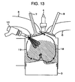
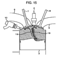
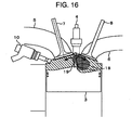
- a third embodiment will be described with reference to Fig. 11 to Fig. 16 .
- a constitution of the third embodiment is the same as that of the second embodiment, but the number of times of injection in a cycle is different.
- the fuel is injected once in the vicinity of the piston bottom dead center.
- the mixed gas excessively concentrates, which might be a factor for increasing a PM.
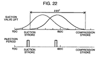
- the third embodiment uses two injection times, i.e., 50% of the fuel is injected in the middle of a suction stroke and the remaining 50% is injected in the vicinity of the piston bottom dead center.
- a relation between an opening period of a suction valve and an injection timing is shown in Fig. 22 .
- a reason why the first fuel injection timing is earlier than the piston bottom dead center is that the first injected fuel forms a homogeneous mixed gas in the combustion chamber.
- a first fuel injection timing is 80 degATDC, and a second fuel injection timing is 160 degATDC.
- An operation of the suction valve is the same as that of Embodiment 2.
- Fig. 11 shows a condition in the combustion chamber at 86 degATDC immediately after the first fuel injection at the piston bottom dead center.
- a suction valve opening timing is 60 degATDC, and a negative pressure in the combustion chamber becomes large between a piston top dead point and 60 degATDC. Therefore, immediately after a suction pipe opens at 60 degATDC, strong flowing air flowing into the combustion chamber through the suction pipe is generated. Therefore, air flows 18 and 19 having high flow velocities are generated in the combustion chamber immediately after the first fuel injection.
- the fuel evaporated at 90 degATDC shown in Fig. 12 is agitated in the combustion chamber, and spreads in the whole area of the combustion chamber.
- Fig. 13 shows a condition in the combustion chamber at 166 degATDC immediately after the second fuel injection
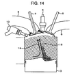
- Fig. 14 shows a condition at 210 degATDC
- Fig. 15 shows a condition at 280 degATDC
- Fig. 16 shows a condition at 330 degATDC, respectively.
- the first injected fuel is distributed in the combustion chamber, but the other constitution is similar to Embodiment 2, and hence the description thereof is omitted.
- the number of times of injection is divided into two, whereby the excessive concentration of the mixed gas around the ignition plug can be suppressed. So, while the PM generated from the mixed gas having a high concentration is decreased, it is possible to achieve both of the decrease of the fuel adhesion to the piston and the early activation of a catalyst.
Landscapes
- Engineering & Computer Science (AREA)
- Chemical & Material Sciences (AREA)
- Combustion & Propulsion (AREA)
- Mechanical Engineering (AREA)
- General Engineering & Computer Science (AREA)
- Combustion Methods Of Internal-Combustion Engines (AREA)
- Electrical Control Of Air Or Fuel Supplied To Internal-Combustion Engine (AREA)
- Exhaust Gas After Treatment (AREA)
- Output Control And Ontrol Of Special Type Engine (AREA)
Applications Claiming Priority (1)
| Application Number | Priority Date | Filing Date | Title |
|---|---|---|---|
| JP2010236060A JP5783701B2 (ja) | 2010-10-21 | 2010-10-21 | 筒内噴射エンジンの制御装置 |
Publications (1)
| Publication Number | Publication Date |
|---|---|
| EP2444643A2 true EP2444643A2 (de) | 2012-04-25 |
Family
ID=45346196
Family Applications (1)
| Application Number | Title | Priority Date | Filing Date |
|---|---|---|---|
| EP11185964A Withdrawn EP2444643A2 (de) | 2010-10-21 | 2011-10-20 | Direkteingespritzter motor und steuereinrichtung dafür |
Country Status (4)
| Country | Link |
|---|---|
| US (1) | US20120097128A1 (de) |
| EP (1) | EP2444643A2 (de) |
| JP (1) | JP5783701B2 (de) |
| CN (1) | CN102454501A (de) |
Families Citing this family (5)
| Publication number | Priority date | Publication date | Assignee | Title |
|---|---|---|---|---|
| JP2016029264A (ja) * | 2012-12-20 | 2016-03-03 | 日産自動車株式会社 | 内燃機関の制御装置及び燃料噴射制御方法 |
| JP2016130495A (ja) * | 2015-01-14 | 2016-07-21 | トヨタ自動車株式会社 | 内燃機関 |
| KR101817049B1 (ko) | 2015-04-14 | 2018-02-21 | 닛산 지도우샤 가부시키가이샤 | 엔진 제어 장치 및 엔진 제어 방법 |
| JP7143755B2 (ja) * | 2018-12-25 | 2022-09-29 | マツダ株式会社 | 圧縮着火式エンジンの制御装置 |
| DE102022101345A1 (de) * | 2022-01-21 | 2023-07-27 | Volkswagen Aktiengesellschaft | Verfahren zum Beheizen einer Abgasnachbehandlungskomponente sowie Verbrennungsmotor |
Citations (2)
| Publication number | Priority date | Publication date | Assignee | Title |
|---|---|---|---|---|
| JP2008151020A (ja) | 2006-12-18 | 2008-07-03 | Hitachi Ltd | 段差を備えたピストンを有した筒内噴射エンジンと制御装置 |
| JP2008175187A (ja) | 2007-01-22 | 2008-07-31 | Mazda Motor Corp | 筒内噴射式エンジンの燃料噴射装置 |
Family Cites Families (17)
| Publication number | Priority date | Publication date | Assignee | Title |
|---|---|---|---|---|
| JPS58107871A (ja) * | 1981-12-22 | 1983-06-27 | Nissan Motor Co Ltd | 内燃機関の燃料噴射装置 |
| JPH0826772B2 (ja) * | 1988-02-26 | 1996-03-21 | トヨタ自動車株式会社 | 火花点火筒内噴射エンジン |
| US4951642A (en) * | 1988-11-19 | 1990-08-28 | Mazda Motor Corporation | Combustion chamber of internal combustion engine |
| JP3380379B2 (ja) * | 1995-04-27 | 2003-02-24 | ヤマハ発動機株式会社 | 筒内噴射エンジン |
| US5775288A (en) * | 1995-08-17 | 1998-07-07 | Yamaha Hatsudoki Kabushiki Kaisha | Combustion chamber |
| JP2001248484A (ja) * | 2000-02-29 | 2001-09-14 | Hitachi Ltd | 筒内噴射エンジン及びその制御装置,制御方法 |
| JP3902732B2 (ja) * | 2001-07-05 | 2007-04-11 | 株式会社日本自動車部品総合研究所 | 直噴火花点火式内燃機関における燃料噴射装置の制御方法 |
| US6845747B2 (en) * | 2002-07-09 | 2005-01-25 | Caterpillar Inc | Method of utilizing multiple fuel injections to reduce engine emissions at idle |
| JP4033160B2 (ja) * | 2004-03-30 | 2008-01-16 | トヨタ自動車株式会社 | 予混合圧縮自着火運転が可能な内燃機関の制御装置 |
| US20080121218A1 (en) * | 2004-12-13 | 2008-05-29 | Caterpillar Inc. | Electric turbocompound control system |
| JP2007077842A (ja) * | 2005-09-13 | 2007-03-29 | Denso Corp | 内燃機関の制御装置 |
| JP4500790B2 (ja) * | 2006-09-01 | 2010-07-14 | 日立オートモティブシステムズ株式会社 | 直噴エンジン |
| JP2008303803A (ja) * | 2007-06-08 | 2008-12-18 | Toyota Motor Corp | 筒内噴射式火花点火内燃機関 |
| JP2009024683A (ja) * | 2007-07-24 | 2009-02-05 | Hitachi Ltd | 複数の噴孔を有するインジェクタ、当該インジェクタを備えた筒内ガソリン噴射型内燃機関とその制御方法 |
| US7992537B2 (en) * | 2007-10-04 | 2011-08-09 | Ford Global Technologies, Llc | Approach for improved fuel vaporization in a directly injected internal combustion engine |
| JP5045600B2 (ja) * | 2008-08-01 | 2012-10-10 | トヨタ自動車株式会社 | 内燃機関 |
| JP2010209868A (ja) * | 2009-03-12 | 2010-09-24 | Nissan Motor Co Ltd | エンジンの着火制御装置 |
-
2010
- 2010-10-21 JP JP2010236060A patent/JP5783701B2/ja not_active Expired - Fee Related
-
2011
- 2011-10-20 EP EP11185964A patent/EP2444643A2/de not_active Withdrawn
- 2011-10-20 US US13/277,941 patent/US20120097128A1/en not_active Abandoned
- 2011-10-21 CN CN201110322667XA patent/CN102454501A/zh active Pending
Patent Citations (2)
| Publication number | Priority date | Publication date | Assignee | Title |
|---|---|---|---|---|
| JP2008151020A (ja) | 2006-12-18 | 2008-07-03 | Hitachi Ltd | 段差を備えたピストンを有した筒内噴射エンジンと制御装置 |
| JP2008175187A (ja) | 2007-01-22 | 2008-07-31 | Mazda Motor Corp | 筒内噴射式エンジンの燃料噴射装置 |
Also Published As
| Publication number | Publication date |
|---|---|
| US20120097128A1 (en) | 2012-04-26 |
| JP5783701B2 (ja) | 2015-09-24 |
| JP2012087706A (ja) | 2012-05-10 |
| CN102454501A (zh) | 2012-05-16 |
Similar Documents
| Publication | Publication Date | Title |
|---|---|---|
| CN102477913B (zh) | 内燃机的燃料喷射控制装置 | |
| RU2603443C2 (ru) | Способ эксплуатации двигателя (варианты) и система двигателя | |
| JP6015575B2 (ja) | エンジンの制御装置 | |
| EP2444643A2 (de) | Direkteingespritzter motor und steuereinrichtung dafür | |
| JP4787867B2 (ja) | 燃料噴射弁、内燃機関の燃料噴射装置及び内燃機関の制御装置 | |
| JP2000204954A (ja) | 内燃機関の制御装置 | |
| JP2014020211A (ja) | 筒内噴射式エンジンの燃料噴射制御装置 | |
| JP4277883B2 (ja) | 筒内噴射式火花点火内燃機関 | |
| EP3460223A1 (de) | Verbrennungsmotorsteuerungsvorrichtung | |
| EP2497920A2 (de) | Verbrennungsmotor | |
| JP6960370B2 (ja) | 内燃機関の燃料噴射制御装置 | |
| JP2012047145A (ja) | 内燃機関の燃料噴射制御装置 | |
| JP2018084202A (ja) | 内燃機関の制御装置 | |
| JP2009102997A (ja) | 火花点火内燃機関 | |
| JP2009046995A (ja) | 内燃機関の可変動弁機構の制御システム | |
| JP7171531B2 (ja) | 燃料噴射制御装置 | |
| JP2014074337A (ja) | 内燃機関の制御装置 | |
| JP5911297B2 (ja) | 内燃機関 | |
| JP2011236834A (ja) | 燃料噴射装置 | |
| CN105358806B (zh) | 引擎的控制设备 | |
| JP6988382B2 (ja) | 内燃機関の制御装置 | |
| JP3969156B2 (ja) | 内燃機関の燃料噴射制御装置 | |
| JP2001207894A (ja) | 直噴エンジン制御装置 | |
| CN107429618A (zh) | 引擎控制装置 | |
| WO2017047248A1 (ja) | 燃料噴射制御装置 |
Legal Events
| Date | Code | Title | Description |
|---|---|---|---|
| 17P | Request for examination filed |
Effective date: 20120302 |
|
| AK | Designated contracting states |
Kind code of ref document: A2 Designated state(s): AL AT BE BG CH CY CZ DE DK EE ES FI FR GB GR HR HU IE IS IT LI LT LU LV MC MK MT NL NO PL PT RO RS SE SI SK SM TR |
|
| AX | Request for extension of the european patent |
Extension state: BA ME |
|
| PUAI | Public reference made under article 153(3) epc to a published international application that has entered the european phase |
Free format text: ORIGINAL CODE: 0009012 |
|
| STAA | Information on the status of an ep patent application or granted ep patent |
Free format text: STATUS: THE APPLICATION HAS BEEN WITHDRAWN |
|
| 18W | Application withdrawn |
Effective date: 20150717 |