EP2436615B1 - Sas de remplissage de déchets - Google Patents
Sas de remplissage de déchets Download PDFInfo
- Publication number
- EP2436615B1 EP2436615B1 EP11007817.7A EP11007817A EP2436615B1 EP 2436615 B1 EP2436615 B1 EP 2436615B1 EP 11007817 A EP11007817 A EP 11007817A EP 2436615 B1 EP2436615 B1 EP 2436615B1
- Authority
- EP
- European Patent Office
- Prior art keywords
- lock
- refuse
- flap
- section
- garbage
- Prior art date
- Legal status (The legal status is an assumption and is not a legal conclusion. Google has not performed a legal analysis and makes no representation as to the accuracy of the status listed.)
- Active
Links
Images


Classifications
-
- B—PERFORMING OPERATIONS; TRANSPORTING
- B65—CONVEYING; PACKING; STORING; HANDLING THIN OR FILAMENTARY MATERIAL
- B65F—GATHERING OR REMOVAL OF DOMESTIC OR LIKE REFUSE
- B65F1/00—Refuse receptacles; Accessories therefor
- B65F1/10—Refuse receptacles; Accessories therefor with refuse filling means, e.g. air-locks
-
- B—PERFORMING OPERATIONS; TRANSPORTING
- B65—CONVEYING; PACKING; STORING; HANDLING THIN OR FILAMENTARY MATERIAL
- B65F—GATHERING OR REMOVAL OF DOMESTIC OR LIKE REFUSE
- B65F2210/00—Equipment of refuse receptacles
- B65F2210/108—Authorization means
Definitions
- the present invention relates to a garbage lock and a refuse container equipped with such a garbage lock.
- waste locks can be briefly opened, for example, by entering a numerical code or other identification measures, so that waste can be thrown by an authorized person.
- a numerical code or other identification measures so that waste can be thrown by an authorized person.
- Such a process is recorded and stored or transmitted telemetrically to a central office, so that it can be determined exactly who has thrown what amount of waste in the bin at what time. In a similar way, the settlement takes place.
- Such a waste gate which provides temporary access to the refuse container, is known from the prior art and is sold, for example, by the applicant.
- An available on the market in various sizes garbage lock comprises a fastened on the lid of a garbage container metal frame and two mounted on the frame lock flaps, which between an open position in which they release an external access to a lock chamber of the garbage lock, and a closed position in the they close the exterior access to the lock room of the garbage lock, are movable.
- the lock flaps can be designed, for example, in the form of semi-cylindrical shells, which are rotatable about a pivot point for closing or opening the lock chamber in opposite directions. The production of such designed waste locks takes place in different sizes in individual manufacturing processes, ie even if the waste locks differ only by their capacity, but otherwise have the same functionalities, the frame and the lock flaps must be individually designed, manufactured and assembled.
- the DE 20 2009 01 677 U1 describes a refuse container with a housing, a rotatably mounted in the housing Einschwanne, which is displaceable between a loading position and an ejection position, and a rotating device which serves to shift the Einschwanne by operating a lever between the loading and the ejection position.
- the housing has an opening through which waste can be introduced into the throw-in pan when it is in its loading position, that is to say in its open position.
- a spring can act, which serves to support a displacement of the throw-in trough from its feed position, that is to say the open position, into its ejection position, that is to say the closed position.
- the DE 19527408 C1 discloses a garbage lock according to the preamble of claim 1.
- the present invention has for its object to provide a garbage lock, which is particularly easy and comfortable to use. Furthermore, the invention has for its object to provide a equipped with such a garbage lock refuse container.
- An exemplary garbage lock comprises at least one lock flap, which is arranged between a closed position in which it is adapted to lock an external access to a lock space of the garbage lock, and an open position in which it is adapted to release the external access to the lock room of the garbage lock, is movable about an axis.
- the refuse lock comprises at least one fastening profile which extends in the direction of the axis defining the movement of the lock flap and is arranged to connect the refuse lock with a refuse container.
- the garbage lock comprises two fastening profiles, for example, parallel to each other in the direction of the movement can extend the lock flap defining axis.
- the attachment profile (s) in the garbage container connected state of the garbage lock may be disposed along a garbage bin formed in the garbage bin.
- the fastening profile (s) preferably comprises a section connected to the garbage lock and a section intended for connection to the garbage container.
- the refuse lock is provided with a first and a second termination device.
- the termination devices are adapted to limit the lock space of the refuse lock to opposite ends of the lock flap with respect to the axis defining the movement of the lock flap.
- the termination devices are designed as separate components from the fastening profile.
- the first termination device is connected to a first end of the attachment profile.
- the second terminator is, however, with a the connected to the first end with respect to the movement of the lock flap defining axis opposite second end of the fastening profile.
- the termination means may be in the form of caps which may be bolted, welded or otherwise connected to the attachment profile.
- the terminating devices preferably consist of a plastic material.
- Another exemplary garbage lock comprises at least one lock flap, which is arranged between a closed position in which it is adapted to close an external access to a lock space of the garbage lock, and an open position in which it is adapted to release the external access to the lock room of the garbage lock to an axis is movable.
- the refuse lock comprises a first and a second closure device, which are set up to limit the lock space at opposite ends of the lock flap with respect to the axis defining the movement of the lock flap.
- At least one of the termination devices is made of a plastic material.
- the refuse lock is equipped with a radio transmitter, which is arranged in the existing of a plastic material terminating device.
- the radio transmitter of the garbage lock can serve to transmit user data, for example data, which shows which user at what time has dumped which amount of waste into a refuse container equipped with the garbage lock, to a control center.
- the radio transmitter can be a GPS transmitter or comprise a GPS transmitter which transmits to the control center the location of the garbage lock and consequently the location of a trash container equipped with the garbage lock.
- the shielding effect of the existing of a plastic material termination device is significantly lower than the shielding effect of a metallic housing. For in the existing of a plastic material End device arranged radio transmitter is therefore an excellent transmission characteristic achievable.
- the radio transmitter can be integrated without additional housing in the existing of a plastic material terminating device in the refuse lock and is therefore well protected from external influences.
- the terminating device consisting of a plastic material can, for example, be manufactured as an injection-molded component and have corresponding receptacles for the radio transmitter and / or further electronic components in its interior.
- the termination device serving for the integration of a radio transmitter is preferably detachable, for example by screwing, connected to the fastening profile, so that the terminating device can be released from the fastening profile if necessary, for example for maintenance purposes, in order to make accessible the radio transmitter arranged in its interior.
- a further exemplary garbage lock comprises at least one lock flap, which is arranged between a closed position in which it is adapted to close an external access to a lock space of the garbage lock, and an open position in which it is adapted to release the external access to the lock room of the garbage lock to an axis is movable.
- the refuse lock comprises at least one fastening profile which extends in the direction of the axis defining the movement of the lock flap and is arranged to connect the refuse lock with a refuse container.
- the fastening profile has a provided for cooperation with the garbage lock mounting portion and provided for cooperation with the garbage container mounting flange.
- the fastening profile can then pass through, for example, a refuse container opening formed in a container body of the refuse container, so that the attachment flange can come into contact with an inner surface of the refuse container body in the system.
- the mounting flange has a first portion and a second portion inclined relative to the first portion. Each section of the mounting flange is provided with a fastening device for connecting the mounting flange to the refuse container.
- the configuration of the fastening profile with a fastening flange which comprises several sections inclined relative to one another makes it possible to adapt the fastening profile to differently shaped refuse container bodies.
- an adaptation to differently curved refuse container body is possible because, depending on the curvature of the refuse container body, either directly to the mounting portion the fastening profile adjacent portion of the mounting flange or one of the mounting portion of the fastening profile remote portion of the mounting flange for connecting the mounting flange can be used with the garbage container.
- the mounting flange may also comprise more than two sections, each of which may be provided with a fastening means for connection, the mounting flange with the refuse container. In principle, then, the more the refuse container body is curved, a further from the mounting portion of the fastening profile remote portion of the mounting flange used to connect the mounting flange with the refuse container.
- the individual sections of the mounting flange can be hinged or rigidly connected to each other.
- the second portion of the mounting flange is inclined relative to the first portion of the mounting flange at an angle of approximately 5 to 25 °.
- further portions of the mounting flange may be inclined at an angle of approximately 5 to 25 degrees relative to an adjacent portion of the mounting flange. It is understood that the angles of inclination of the sections of the mounting flange relative to one another can be adapted to the shapes of the container bodies of the garbage containers intended for connection to the garbage lock.
- the sections of the mounting flange can each be made flat.
- the first and second portions of the mounting flange may also be curved, with the curvature of the first portion being matched to the curvature of a component suitable for connection to the mounting flange, such as a container body, of a first refuse container.
- the curvature of the second portion of the mounting flange is preferably adapted to the curvature of a suitable for connection to the mounting flange component, for example, a container body, a second refuse container.
- Curved trained Befest Trentsflanschabitese may be more difficult to manufacture than flat mounting flange sections, but they allow an even better connection of the mounting flange to a suitable component, such as a container body to be equipped with the garbage lock refuse container.
- a garbage lock according to the invention comprises at least one lock flap, which between a closed position in which they do so is arranged to close an exterior access to a lock space of the garbage lock, and an open position in which it is adapted to release the external access to the lock room of the garbage lock, about an axis is movable. Furthermore, the refuse lock comprises a pretensioning device which is set up to bias the lock flap into its open position, ie to urge it into its open position.
- a refuse lock equipped with a pretensioning device biasing the lock flap in its open position is particularly easy and comfortable to operate, since the pretensioning device ensures automatic opening of the lock flap.
- the garbage lock further comprises a locking mechanism for locking the lock door in its closed position.
- the biasing means may then be adapted to automatically move the gate flap to its open position upon unlocking the locking mechanism.
- the locking mechanism may be configured to be unlocked by inserting a locking device into a corresponding locking device receptacle.
- the locking device may be designed in the form of a mechanically acting key, but preferably in the form of an RFID key.
- the closing device receptacle is equipped with a magnetic sensor, for example in the form of a reed contact or a Hall sensor.
- the magnetic sensor responds to the presence of a magnetic element integrated in the closing device and, in this case, ensures the supply of the closing device receptacle with electrical energy, for example by closing a corresponding electric circuit.
- a closing device receptacle equipped with a magnetic sensor, in combination with a closing device comprising a magnetic element enables the realization of a particularly power-saving operation of the closing device receptacle.
- Another exemplary garbage lock comprises at least one lock flap, which is arranged between a closed position in which it is adapted to close an external access to a lock space of the garbage lock, and an open position in which it is adapted to release the external access to the lock room of the garbage lock to an axis is movable.
- the refuse lock comprises an actuating lever for manually moving the lock flap from its closed position to its open position and / or from its open position to its closed position, wherein the lock flap and the actuating lever are connected to each other via a ratchet mechanism.
- a connected via a ratchet mechanism with the lock flap actuating lever is easy and comfortable to use, since the actuating lever has a short operating path.
- the handle of the operating lever is preferably made of an antibacterial material. This can improve hygiene.
- Another exemplary garbage lock comprises at least one lock flap, which is arranged between a closed position in which it is adapted to close an external access to a lock space of the garbage lock, and an open position in which it is adapted to release the external access to the lock room of the garbage lock to an axis is movable.
- the lock flap is, for example by means of an actuating lever, manually movable from its open position to its closed position or from its closed position to its open position.
- the refuse lock comprises a biasing device which is adapted to be biased by a manual operation of the lock flap and apply a biasing force directed counter to the manual actuation direction of the lock flap on the lock flap.
- the force which a user of the garbage lock applies when opening or closing the lock manually is used to bias the pretensioner.
- the biasing means is enabled to exert a biasing force directed counter to the manual operating direction of the sluice flap on the sluice flap. Consequently, a manually-opening sluice flap can be automatically closed with the aid of the pretensioning device, whereas a sluice flap which can be manually closed can be opened automatically with the aid of the pretensioning device.
- the biasing means may be coupled to a generator such that the energy released during relaxation of the biasing means drives the generator.
- the energy released during the relaxation of the pretensioner is used by the generator for power generation.
- the electrical energy provided by the generator can be used to supply electrical and / or electronic components of the waste gate, for example a radio transmitter or the like.
- the generator can act as a damper for damping the movement of the lock flaps in their open position or provide a formed in the form of a separate component damper with electrical energy.
- the refuse lock can also be equipped with an accumulator which can temporarily store energy generated by the generator but not directly used by an electrical consumer.
- Another exemplary garbage lock comprises at least one lock flap, which is arranged between a closed position in which it is adapted to close an external access to a lock space of the garbage lock, and an open position in which it is adapted to release the external access to the lock room of the garbage lock to an axis is movable.
- the lock flap is manually movable from its open position to its closed position.
- the refuse lock can be equipped with a corresponding operating lever.
- the refuse lock comprises a locking mechanism for locking the lock flap in its closed position, which is adapted to be unlocked by inserting a locking device into a corresponding locking device receptacle.
- a holding mechanism is provided which is adapted to hold a locking device inserted into the locking device receptacle for unlocking the locking mechanism in its position in the locking device receptacle as long as the locking mechanism is unlocked.
- the holding mechanism is further adapted to release the locking device only when the locking mechanism locks the lock flap after manually moving the lock flap from its open position to its closed position again in its closed position.
- Another exemplary garbage lock comprises at least one lock flap, which is arranged between a closed position in which it is adapted to close an external access to a lock space of the garbage lock, and an open position in which it is adapted to release the external access to the lock room of the garbage lock to an axis is movable.
- the sluice flap is provided with a start-up section along a sluice-flap edge delimiting the sluice chamber in the open position of the sluice flap, which extends from the sluice flap edge in a direction facing away from the sluice chamber or in a direction facing the sluice chamber.
- the start-up section ensures that garbage bags inserted into the lock space of the garbage lock are pressed into the lock space when the lock flap is closed, instead of being squeezed "like a pincers" by the closing lock flap. This can minimize the risk of damaging the garbage bags and thereby contaminating the garbage lock.
- the run-up portion may extend along the entire sluice flap edge. However, if desired or necessary, the sluice flap edge may be provided with a run-up portion only along a portion.
- the start-up section When the start-up section extends in a direction away from the lock space, the start-up section preferably forms an angle of approximately 120 to 160 ° with a region of a gland flap outer surface adjacent to the lock flap edge, and the angle between the start section and the region adjacent to the lock flap edge is particularly preferred the lock flap outer surface approximately 130 to 150 °.
- the run-up section when the run-up section extends in a direction facing the lock space, the run-up section preferably forms an angle of approximately 120 to 160 ° with an area of a lock flap inner surface adjacent to the lock flap edge, the angle between the run-on section and the latter is particularly preferred Approximately 130 to 150 ° of the area of the flap flap inner surface adjacent to the sluice flap edge.
- a further garbage lock comprises a first and a second lock flap.
- the lock flaps are movable between a closed position and an open position. In its closed position, the lock flaps are adapted to close an external access to a lock space of the refuse lock and to release a lock opening connecting the lock space with the interior of a refuse container equipped with the refuse lock. In contrast, in their open position, the lock flaps are adapted to release the external access to the lock chamber of the refuse lock and to close the lock opening connecting with the interior of a refuse container equipped with the refuse lock.
- the first lock flap comprises a base body designed in the form of a circular cylinder segment, which is rotatable about a rotation axis in such a way that the base body describes a circular-cylindrical movement path during its rotational movement about the rotation axis.
- the second lock flap can be pivoted about a pivot axis which extends in the area of a circumference of the circular-cylindrical movement path described by the base body of the first lock flap during its rotation about the axis of rotation substantially parallel to the axis of rotation.
- a garbage lock which is equipped with a rotatable first lock flap and a pivotable second lock flap, has the advantage that a "forceps effect" of the Sehleusenklappen, which can lead to damage introduced into the lock room of the garbage bag garbage bags is reliably avoided. Instead, the garbage bag is pressed by the pivotable about a pivot axis second lock flap into the lock chamber.
- a garbage lock comprises a first and a second sluice flap, which between a closed position, in which they are adapted to close an external access to a lock room of the garbage lock and release the lock space with the interior of a garbage-equipped refuse container connecting opening , and an open position in which they are set up to release the outside access to the lock room of the garbage lock and the lock room to close with the interior of a garbage container equipped with the garbage lock connection opening to a common axis of rotation in opposite directions are rotatable so that the first lock flap is at least partially received in the open position of the lock flaps in the second lock flap.
- the first and second sluice valves each comprise a base body designed in the form of a circular cylinder segment.
- the base body of the first sluice flap has a smaller radius than the base body of the second sluice flap.
- the first lock flap can also be connected to an insert which reduces the volume of the lock space.
- a garbage lock designed in this way addresses the problem that a garbage sluice due to the fact that a garbage bag in principle has the tendency to approach a spherical shape, should have dimensions that come as close as possible to a spherical shape.
- the problem may arise that the extension of the lock flaps along its axis of rotation in relation to a diameter of a circular cylindrical path of movement, which is described by substantially identically formed base body comprehensive flap valves is too low.
- the shape of the lock chamber defined by the lock flaps can again be approximated to the desired spherical shape by the above-described embodiment of the refuse lock with differently designed lock flaps.
- the base body of the first lock flap can have a first bearing element along an edge extending substantially parallel to the axis of rotation of the lock flap.
- the first bearing element is preferably configured to engage a complementary second bearing element when the gate valves are in their open position. As a result of the interaction of the first bearing element with the complementary second bearing element, the first lock flap is held at the desired distance from the second lock flap which at least partially accommodates the first lock flap.
- An inventive refuse container designed in particular as a refuse container, comprises a container body in which a refuse insertion opening is formed. Furthermore, the refuse container comprises a refuse lock arranged above in the area of the refuse insertion opening, which may for example be provided in the region of a lid of the refuse container.
- the refuse container according to the invention preferably further comprises a seal with a first sealing surface, which cooperates with a region of a container body outer surface adjacent to the refuse insertion opening. Furthermore, the seal has a second sealing surface which cooperates with an outer surface of the refuse lock. Finally, the seal may have a fastening projection comprising a first section extending through the refuse insertion opening and a second section adjoining a region of a container body inner surface adjacent to the refuse insertion opening.
- the refuse container according to the invention may be provided with a distribution device, as described for example in the EP 1 231 161 A1 is described.
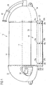
- One in the FIGS. 1 to 5 illustrated refuse lock 10 comprises a first and a second lock flap 12, 14 (see Fig. 3 ), each comprising a formed in the form of a circular cylinder segment base body.
- the lock flaps 12,14 are rotatable about a common axis of rotation R in opposite directions to adjust the lock flaps 12, 14 between a closed position and an open position.
- the lock flaps 12, 14 close an external access to a lock chamber 16 of the refuse lock 10 and release a lock opening 16 connecting the lock chamber 16 with the interior of a refuse container equipped with the refuse 10 connection opening.
- the lock flaps 12, 15 release the external access to the lock chamber 16 of the refuse receptacle 10.
- the lock flaps 12, 14 are illustrated in their open position with solid lines and in its closed position with dashed lines.
- the garbage lock 10 further comprises two fastening profiles 18 which extend along a circumferential edge of a circular-cylindrical movement path described by the lock flaps 12, 14 in their movement between their open position and their closed position substantially parallel to the axis of rotation R.
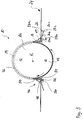
- Each fastening profile 18 comprises a mounting portion 20 which is provided for cooperation with a component of the refuse lock 10. From the mounting portion 20, a mounting flange 22, which is provided to extend with one in the FIGS. 2 to 5 partially illustrated refuse container 24 zusacnmenzu lecture. How best in the FIGS. 1 and 3 to 5 can be seen, the mounting flange 22 has three sections 26a, 26b, 26c, which are each inclined relative to each other.
- the inclination of the mounting flange portions 26a, 26b, 26c is such that an angle between a mounting flange portion 26a, 26b, 26c and the mounting portion 20 or a surface parallel to the mounting portion 20 is greater, the farther the corresponding mounting flange portion 26a, 26b, 26c is removed from the mounting portion 20.
- the mounting portion 20 and the immediately adjacent to the mounting portion 20 mounting flange portion 26 a form an angle of approximately 90 °.
- the mounting flange portion 26b separated from the mounting portion 20 by the mounting flange portion 26a forms an angle of approximately 105 ° with an imaginary surface parallel to the mounting portion 20.
- the mounting flange portion 26c which is separated from the mounting portion 20 by the mounting flange portions 26a and 26b, eventually forms an angle of approximately 110 ° with an imaginary surface parallel to the mounting portion 20.
- Each mounting flange portion 26a, 26b, 26c is provided with a plurality of fastening means 28a, 28b, 28c formed in the form of mounting holes.
- the fastening devices 28a, 28b, 28c serve to receive a fastener 30 formed, for example, in the form of a screw or a rivet (see FIG FIGS. 3 to 5 ).
- a fastener 30 formed, for example, in the form of a screw or a rivet (see FIG FIGS. 3 to 5 ).
- the immediately adjacent to the mounting portion 20 mounting flange portion 26a can be used to connect the garbage 10 are used with the refuse container 24 when connected to the connection with the refuse lock 10 component, that is connected to the connection with the refuse lock 10 area of a container body of the refuse container 24 has a substantially planar shape.
- the use of the attachment flange portion 26b lends itself when the refuse lock 10 is to be connected to a component of the refuse container 24 which is slightly curved (see FIG Fig. 4 ).
- the attachment flaring section 26 c is particularly well suited to connect the refuse lock 10 with a strongly curved component of the refuse container 24.
- the mounting flange portions 26a, 26b, 26c are flat. However, if desired, the mounting flange portions 26a, 26b, 26c may be curved. The curvature of the mounting flange portions 26a, 26b, 26c is then adapted to the curvature of the intended for connection to the mounting flange 22 components of various refuse containers 24 meaningful way.
- the waste gate 10 further comprises two cap-shaped closing devices 32, 34 designed as separate components.
- the closing devices 32, 34 enclose the lock chamber 16 at opposite ends of the lock flaps 12, 14 with respect to the rotation axis R of the lock flaps 12, 14.
- the formation of the fastening profiles 18, the lock flaps 12, 14 and the termination devices 32, 34 as separate components results in a modular construction of the waste gate 10.
- a variation of the size, that is the capacity of the waste gate 10 is solely due to a variation of the extent of the lock flaps 12, 14 and the fastening profiles 18 in the direction of the axis of rotation R possible.
- the shape and the design of the termination devices 32, 34 need not be changed.
- the termination devices 32, 34 are made of a plastic material. As in Fig. 1 is shown, the termination device 32 is the recording of a radio transmitter 36.
- the radio transmitter 36 is used to send user data of the garbage lock to a central office. For example, the radio transmitter 36 transmits to the control center which user has thrown what amount of waste into the waste gate 10 at what time. Furthermore, the radio transmitter 36 is equipped with a GPS device which transmits the location of the waste gate 10 and the refuse container 24 to the control center. Due to the configuration of the termination device 32 made of a plastic material, the shielding of the radio transmitter 36 is minimized, whereby good transmitter powers can be achieved.
- the refuse lock 10 further includes biasing means, not illustrated in the figures, for biasing the lock flaps 12, 14 to their open position.
- the biasing means may comprise, for example, a spring.
- the refuse lock 10 is equipped with a locking mechanism, also not illustrated in the figures, which locks the lock flaps 12, 14 in their closed position.
- the biasing means is coupled to the locking mechanism such that the biasing means for an automatic Movement of the lock flaps 12, 14 provides in its open position as soon as the locking mechanism has reached an unlocked position.
- the locking mechanism is unlocked by inserting a locking device into a corresponding locking device receptacle.
- the locking device can be designed in the form of a mechanical key. It makes sense, however, the locking device is designed in the form of an RFID key and can thus be used to uniquely identify the user of the garbage lock.
- a locking device embodied in the form of an RFID key can communicate, for example, with a corresponding RFID receiving device, which can be arranged, for example, in one of the terminating devices 32, 34.
- the closing device receptacle is equipped with a magnetic sensor in the form of a reed contact or a Hall sensor.
- the magnetic sensor responds to the presence of a magnetic element integrated in the closing device and in this case ensures the supply of the closing device receptacle with electrical energy by closing a corresponding electric circuit.
- This embodiment of the closing device receptacle and the closing device enables a particularly power-saving operation of the closing device receptacle.
- the refuse lock 10 further includes an operating lever 38.
- the operating lever 38 is provided with a handle 40 made of an antibacterial material.
- the lock flaps 12, 14 can be brought manually from its open position, in which they are moved by means of the biasing means, back into its closed position.
- the lock flaps 12, 14 and the operating lever 38 are connected to each other via a ratchet mechanism. Thereby, the actuating travel of the operating lever 38 can be shortened in an advantageous manner.
- the manual force applied by the user of the refuse lock 10 during the manual actuation of the lock flaps 12, 14 by means of the actuation lever 38 is used to pretension the pretensioner, which is then again used for automatic opening of the lock flaps 12 during the next use of the refuse lock 10. 14 can provide.
- the biasing means is coupled to a generator, also not illustrated in the figures.
- the energy released during the relaxation of the pretensioning device, that is to say when opening the lock flaps 12, 14, drives the generator.
- the electrical energy generated by the generator is used to supply the electrical and electronic components of the refuse lock 10, for example the radio transmitter 36. This can be done on one Connection of the refuse lock 10 to be dispensed with an electrical supply network.
- the generator acts as a damper for damping the movement of the lock flaps 12, 14 in its open position.
- the garbage lock 10 further includes a retaining mechanism that holds the lock inserted into the lock receptacle for unlocking the lock mechanism in position within the lock receptacle as long as the lock mechanism is unlocked.
- the retaining mechanism releases the locking device only when the locking mechanism locks the lock flaps 12, 14 back to its closed position after manual movement of the lock flaps 12, 14 by means of the actuating lever 38 from its open position to its closed position. This prevents a user after inserting his garbage in the lock chamber 16 of the garbage lock 10, the garbage lock 10 is no longer properly closed.
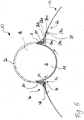
- the refuse lock 10 can be manufactured in different sizes by shortening the extension of the lock flaps 12, 14 and the fastening profiles 18 in the direction of the axis of rotation R of the lock flaps 12, 14. With a corresponding shortening of these components in the direction of the axis of rotation R, however, the problem may arise that the lock chamber 16 is then no longer dimensioned so that its shape is adapted to the tendentially spherical shape of a garbage bag. In other words, the ratio between the diameter of the lock chamber 16 and the longitudinal extent of the lock chamber 16 in the direction of the axis of rotation R becomes too large.
- the first lock flap as in Fig. 6 Shown by the arrangement of the first lock flap 12 at a distance from the second lock flap 14, the volume of the lock chamber 16 in the direction of the diameter of the reduced by the lock flaps 12, 14 described circular cylindrical paths of movement.
- the shape of the lock chamber 16 is optimized for receiving a garbage bag approaching in shape to a spherical shape.
- the base body of the first lock flap 12 has a first bearing element 42.
- the first bearing element 42 comes into abutment against a second bearing element 44 when the lock flaps 12, 14 are moved from their closed position to their open position.
- the first bearing element 42 rests on the second bearing element 44.
- the second bearing element 44 is formed integrally with the fastening profile 18 and extends from the mounting section 20 of the fastening profile 18 in a direction substantially perpendicular to the lock chamber 16.
- a sealing element 46 ensures a trained in the refuse container 24 refuse insertion opening relative to the arranged in the region of the refuse opening garbage 10th
- the sealing element 46 comprises a first sealing surface 48, which cooperates with an adjacent to the refuse insertion portion of an outer surface of the container body of the refuse container 20.
- the sealing element 46 comprises a second sealing surface 50, which cooperates with an outer surface of the refuse lock 10.
- the first and second sealing surfaces 48, 50 extend substantially perpendicular to each other.
- the sealing element 46 is provided with a fastening projection 52.
- the attachment projection 52 includes a first portion 54 extending through the refuse container body formed in the refuse container body and a second portion 56 abutting a portion of an inner surface of the refuse container body adjacent to the refuse insertion opening.
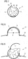
- Fig. 7 shows an embodiment of the garbage lock 10, which, as well as in the FIGS. 1 to 6 illustrated arrangements, with circular cylinder segment-shaped lock flaps 12, 14 is equipped.
- the sluice valves 12, 14 are moved by rotation in opposite directions about a common axis of rotation R between their open position and their closed position.
- one of the two lock flaps 12, 14 is now along a lock space 16 provided in the open position of the lock flaps 12, 14 limiting the lock flap edge 58 with a start-up section 60.
- a run-up portion 60 provided on the first sluice flap 12 is illustrated with a broken line
- a run-up portion 60 provided on the second sluice flap 14 is shown with a solid line.
- both lock flaps 12, 14 can be provided with corresponding start-up sections 60.
- the start-up section 60 provided on the second lock flap 14 extends from the lock flap edge 58 of the second lock flap 14 in a direction away from the lock chamber 16, wherein the start-up section 60 makes an angle of approximately one with an area of an outer surface of the second lock flap 14 adjacent to the lock flap edge 58 150 ° forms.
- the start-up section 60 provided on the first lock flap 12 extends from the lock flap edge 58 of the first lock flap 12 in a direction facing the lock space 16, wherein the start-up section 60 is at an angle of approximately one with an area of an inner surface of the first lock flap 12 adjacent to the lock flap edge 58 150 ° forms.
- Each of the two start-up sections 60 presses garbage bags introduced into the lock chamber 16 when closing the lock flaps 12, 14 into the lock chamber 16 and thereby prevents damage to the garbage bags by a "forceps effect" of the lock flaps 12, 14.
- FIGS. 8 and 9 show another embodiment of a waste gate 10.
- the in the FIGS. 8 and 9 shown garbage lock 10 differs from the in the FIGS. 1 to 7 illustrated arrangements by the design of the lock flaps 12,14.
- the first lock flap 12 is provided with a formed in the form of a circular cylinder segment base body.
- the base body is rotatable about a rotation axis R, so that the lock flap base body in its rotational movement about the rotation axis R, similar to the base body of the lock flaps 12, 14 of the in the FIGS. 1 to 7 illustrated waste locks 10, describes a circular cylindrical path of movement.
- the second lock flap 14 is pivotable about a pivot axis S which extends in the region of a circumference of the circular-cylindrical movement path described by the base body of the first lock flap 12 in its rotation about the rotation axis R substantially parallel to the rotation axis R.
- This embodiment of the lock flaps 12, 14 causes one in the lock chamber 16 of the refuse lock 10th introduced garbage bag when closing the sluice valves 12, 14 is pressed into the lock chamber 16 and is not damaged by a "forceps effect" of the sluice valves.
Landscapes
- Engineering & Computer Science (AREA)
- Mechanical Engineering (AREA)
- Refuse Receptacles (AREA)
Claims (19)
- Sas à déchets (10) comprenant :- au moins un clapet de sas (12, 14) qui est mobile autour d'un axe (R) entre une position de fermeture, dans laquelle il est agencé pour fermer un accès extérieur à une chambre de sas (16) du sas à déchets (10), et une position d'ouverture, dans laquelle il est agencé pour libérer l'accès extérieur à la chambre de sas (16) du sas à déchets (10), etcaractérisé par un moyen de précontrainte qui est agencé pour précontraindre le clapet de sas (12, 14) dans sa position d'ouverture.
- Sas à déchets selon la revendication 1,
caractérisé en ce que le sas à déchets (10) comprend en outre un mécanisme de verrouillage destiné à verrouiller le clapet de sas (12, 14) dans sa position de fermeture, et en ce que le moyen de précontrainte est agencé pour déplacer le clapet de sas (12, 14) dans sa position d'ouverture après le déverrouillage du mécanisme de verrouillage. - Sas à déchets selon la revendication 2,
caractérisé en ce que le mécanisme de verrouillage est agencé pour être déverrouillé par insertion d'un dispositif de fermeture dans un logement de dispositif de fermeture correspondant, le logement de dispositif de fermeture étant de préférence équipé d'un capteur magnétique et le dispositif de fermeture étant de préférence équipé d'un élément magnétique, et dans lequel le capteur magnétique du logement de dispositif de fermeture est de préférence agencé pour assurer l'alimentation du logement de dispositif de fermeture en énergie électrique en réaction à la présence d'un élément magnétique intégré dans le dispositif de fermeture. - Sas à déchets selon l'une des revendications 1 à 3,
caractérisé par :- au moins un profilé de fixation (18) qui s'étend dans la direction de l'axe (R) et qui est agencé pour relier le sas à déchets (10) à un conteneur à déchets (24), et- un premier et un deuxième moyen de terminaison (32, 34) qui sont agencés pour délimiter la chambre de sas (16) aux extrémités opposées du clapet de sas (12, 14) par rapport à l'axe (R) et qui sont agencés comme des composants séparés du profilé de fixation (18), le premier moyen de terminaison (32, 34) étant relié à une première extrémité du profilé de fixation (18) et le deuxième moyen de terminaison (32, 34) étant relié à une deuxième extrémité du profilé de fixation (18) opposée à la première extrémité par rapport à l'axe (R). - Sas à déchets selon la revendication 4,
caractérisé en ce qu'au moins un des moyens de terminaison (32, 34) est constitué d'un matériau plastique et qu'un émetteur radio (36) est disposé dans le moyen de terminaison (32, 34) constitué d'un matériau plastique. - Sas à déchets selon la revendication 4 ou la revendication 5,
caractérisé en ce que le profilé de fixation (18) comprend une section de montage (20) destinée à coopérer avec un composant du sas à déchets (10) ainsi qu'une bride de fixation (22) destinée à coopérer avec le conteneur à déchets (24), laquelle bride comprend une première section (26a) ainsi qu'une deuxième section (26b) inclinée par rapport à la première section (26a), chaque section (26a, 26b) de la bride de fixation (22) étant pourvue d'un moyen de fixation (28a, 28b) destiné à relier la bride de fixation (22) au conteneur à déchets (24). - Sas à déchets selon la revendication 6,
caractérisé en ce que la deuxième section (26b) de la bride de fixation (22) est inclinée d'un angle d'environ 5 à 25° par rapport à la première section (26a) de la bride de fixation (22). - Sas à déchets selon la revendication 6 ou la revendication 7,
caractérisé en ce que la première et la deuxième section (26a, 26b) de la bride de fixation (22) ont une forme courbée, la courbure de la première section (26a) étant adaptée à la courbure d'un composant d'un premier conteneur à déchets (24) approprié à la liaison avec la bride de fixation (22) et la courbure de la deuxième section (26b) étant adaptée à la courbure d'un composant d'un deuxième conteneur à déchets (24) approprié à la liaison avec la bride de fixation (22). - Sas à déchets selon l'une des revendications 1 à 8,
caractérisé par- un levier d'actionnement (38) destiné à déplacer manuellement le clapet de sas (12, 14) de sa position de fermeture dans sa position d'ouverture et/ou de sa position d'ouverture dans sa position de fermeture, le clapet de sas (12, 14) et le levier d'actionnement (38) étant reliés l'un à l'autre par un mécanisme à cliquet. - Sas à déchets selon l'une des revendications 1 à 9,
caractérisé en ce que le clapet de sas (12, 14) est apte à être déplacé manuellement de sa position d'ouverture dans sa position de fermeture ou de sa position de fermeture dans sa position d'ouverture, et en ce que le moyen de précontrainte est agencé pour être précontraint par un actionnement manuel du clapet de sas (12, 14) et appliquer sur le clapet de sas (12, 14) une force de précontrainte dirigée à l'encontre de la direction de l'actionnement manuel du clapet de sas (12, 14). - Sas à déchets selon la revendication 10,
caractérisé en ce que le moyen de précontrainte est couplé à un générateur de telle façon que l'énergie libérée lors de la détente du moyen de précontrainte entraîne le générateur, le générateur agissant en particulier comme amortisseur destiné à amortir le déplacement des clapets de sas (12, 14) dans leur position d'ouverture ou alimentant en énergie électrique un amortisseur réalisé sous la forme d'un composant distinct. - Sas à déchets selon l'une des revendications 1 à 11,
caractérisé en ce que le clapet de sas (12, 14) est apte à être déplacé manuellement de sa position d'ouverture dans sa position de fermeture,- un mécanisme de verrouillage destiné à verrouiller le clapet de sas (12, 14) dans sa position de fermeture étant agencé pour être déverrouillé par insertion d'un dispositif de fermeture dans un logement de dispositif de fermeture correspondant, et- un mécanisme de maintien étant agencé pour maintenir un dispositif de fermeture inséré dans le logement de dispositif de fermeture afin de déverrouiller le mécanisme de verrouillage dans sa position dans le logement de dispositif de fermeture aussi longtemps que le mécanisme de verrouillage est déverrouillé et pour libérer le dispositif de fermeture seulement lorsque le mécanisme de verrouillage verrouille de nouveau le clapet de sas (12, 14) dans sa position de fermeture après le déplacement manuel du clapet de sas (12, 14) de sa position d'ouverture dans sa position de fermeture. - Sas à déchets selon l'une des revendications 1 à 12,
caractérisé en ce que le clapet de sas (12, 14) est pourvu le long d'un bord de clapet de sas (58) d'une section de départ (60) délimitant la chambre de sas (16) dans la position d'ouverture du clapet de sas (12, 14), laquelle s'étend depuis le bord de clapet de sas (58) dans une direction opposée à la chambre de sas (16) ou dans une direction tournée vers la chambre de sas (16). - Sas à déchets selon la revendication 13,
caractérisé en ce que la section de départ (60) forme un angle d'environ 120 à 160° avec une zone d'une surface extérieure du clapet de sas ou d'une surface intérieure du clapet de sas qui est adjacente au bord de clapet de sas (58). - Sas à déchets selon l'une des revendications 1 à 14,
caractérisé en ce que le sas à déchets (10) comprend un premier et un deuxième clapet de sas (12, 14) aptes à être déplacés entre une position de fermeture, dans laquelle ils sont agencés pour fermer l'accès extérieur à la chambre de sas (16) du sas à déchets (10) et libérer une ouverture de liaison reliant la chambre de sas (16) à l'intérieur d'un conteneur à déchets (24) équipé du sas à déchets (10), et une position d'ouverture, dans laquelle ils sont agencés pour libérer l'accès extérieur à la chambre de sas (16) du sas à déchets (10) et fermer l'ouverture de liaison reliant la chambre de sas (16) à l'intérieur d'un conteneur à déchets (24) équipé du sas à déchets (10),- le premier clapet de sas (12) comprenant un corps de base réalisé sous la forme d'un segment de cylindre circulaire susceptible de tourner autour d'un axe de rotation (R) de telle façon que le corps de base décrive une trajectoire cylindrique circulaire lors de son mouvement de rotation autour de l'axe de rotation (R), et- le deuxième clapet de sas (14) étant susceptible de pivoter autour d'un axe de pivotement (S) qui s'étend sensiblement parallèlement à l'axe de rotation (R) dans la zone d'un périmètre de la trajectoire cylindrique circulaire décrite par le corps de base du premier clapet de sas (12) lors de son mouvement de rotation autour de l'axe de rotation (R). - Sas à déchets selon l'une des revendications 1 à 14,
caractérisé en ce que le sas à déchets (10) comprend un premier et un deuxième clapet de sas (12, 14) qui sont susceptibles de tourner en sens opposés autour d'un axe de rotation (R) commun entre une position de fermeture, dans laquelle ils sont agencés pour fermer l'accès extérieur à la chambre de sas (16) du sas à déchets (10) et libérer une ouverture de liaison reliant la chambre de sas (16) à l'intérieur d'un conteneur à déchets (24) équipé du sas à déchets (10), et une position d'ouverture, dans laquelle ils sont agencés pour libérer l'accès extérieur à la chambre de sas (16) du sas à déchets (10) et fermer l'ouverture de liaison reliant la chambre de sas (16) à l'intérieur d'un conteneur à déchets (24) équipé du sas à déchets (10), de telle façon que dans la position d'ouverture des clapets de sas (12, 14) le premier clapet de sas (12) soit logé au moins partiellement dans le deuxième clapet de sas (14),- les premier et deuxième clapets de sas (12, 14) comprenant chacun un corps de base réalisé sous la forme d'un segment de cylindre circulaire, le corps de base du premier clapet de sas (12) ayant un rayon plus faible que le corps de base du deuxième clapet de sas (14) ou le premier clapet de sas (12) étant relié à un insert diminuant le volume de la chambre de sas (16). - Sas à déchets selon la revendication 16,
caractérisé en ce que le corps de base du premier clapet de sas (12) comprend le long d'un bord s'étendant sensiblement parallèlement à l'axe de rotation (R) des clapets de sas (12, 14) un premier élément d'appui (42) qui est agencé pour venir en appui sur un deuxième élément d'appui (44) complémentaire lorsque les clapets de sas (12, 14) se trouvent dans leur position d'ouverture. - Conteneur à déchets (10), notamment conteneur à déchets de grande contenance, comprenant :- un corps de conteneur dans lequel une ouverture d'introduction des déchets est réalisée, et- un sas à déchets (10) selon l'une des revendications précédentes disposé dans la zone de l'ouverture d'introduction des déchets.
- Conteneur à déchets selon la revendication 18,
caractérisé par un élément d'étanchéité (46) comportant une première surface d'étanchéité (48) qui coopère avec une zone d'une surface extérieure du corps de conteneur adjacente à l'ouverture d'introduction des déchets, une deuxième surface d'étanchéité (50) qui coopère avec une surface extérieure du sas à déchets (10), et une saillie de fixation (52) qui comprend une première section (54) qui s'étend à travers l'ouverture d'introduction des déchets et une deuxième section (56) s'appuyant sur une zone d'une surface intérieure d'un corps de conteneur adjacente à l'ouverture d'introduction des déchets.
Applications Claiming Priority (1)
| Application Number | Priority Date | Filing Date | Title |
|---|---|---|---|
| DE102010046852.5A DE102010046852B4 (de) | 2010-09-29 | 2010-09-29 | Müllschleuse und Müllbehälter |
Publications (3)
| Publication Number | Publication Date |
|---|---|
| EP2436615A2 EP2436615A2 (fr) | 2012-04-04 |
| EP2436615A3 EP2436615A3 (fr) | 2012-08-29 |
| EP2436615B1 true EP2436615B1 (fr) | 2016-03-16 |
Family
ID=44719091
Family Applications (1)
| Application Number | Title | Priority Date | Filing Date |
|---|---|---|---|
| EP11007817.7A Active EP2436615B1 (fr) | 2010-09-29 | 2011-09-26 | Sas de remplissage de déchets |
Country Status (3)
| Country | Link |
|---|---|
| EP (1) | EP2436615B1 (fr) |
| DE (1) | DE102010046852B4 (fr) |
| ES (1) | ES2570779T3 (fr) |
Families Citing this family (2)
| Publication number | Priority date | Publication date | Assignee | Title |
|---|---|---|---|---|
| DE102017104975A1 (de) | 2017-03-09 | 2018-09-13 | Thomas Schneider | Umfüllvorrichtung |
| DE102023118076A1 (de) * | 2023-07-07 | 2025-01-09 | Joba Recycling Solutions Gmbh | Kleidercontainer zum Einwerfen von Altkleidern |
Family Cites Families (12)
| Publication number | Priority date | Publication date | Assignee | Title |
|---|---|---|---|---|
| DE4413034A1 (de) * | 1994-04-15 | 1995-10-19 | Alois Ziswiler | Einfüllvorrichtung für Stoffe |
| DE9407814U1 (de) * | 1994-05-11 | 1995-09-14 | Rheinwerk Entsorgungsprodukte GmbH & Co KG, 47918 Tönisvorst | Abfallbehälter |
| DE19527408C1 (de) * | 1995-07-27 | 1996-12-12 | Ingbuero Peters | Einfüllschleuse für Behälter |
| ATE163625T1 (de) * | 1995-09-15 | 1998-03-15 | Csl Computer Service Lauchhamm | Verfahren und einrichtung zur erfassung von sammelmengen, insbesondere von abfall aus haushalten |
| DE19541010C1 (de) * | 1995-11-03 | 1997-04-24 | Ifau Umweltberatung Gmbh | Abfallbehältergehäuse mit Einwurfschleuse |
| NL1006649C2 (nl) * | 1997-07-23 | 1999-01-26 | Ronald Barend Van Santbrink | Inrichting voor het geïndividualiseerd inbrengen van voorwerpen. |
| DE59906561D1 (de) * | 1998-05-10 | 2003-09-18 | Sulo Umwelttechnik Gmbh & Co Kg | Einwurfschleuse für eingehauste Abfallbehälter |
| EP1231161A1 (fr) | 2001-02-13 | 2002-08-14 | Elektromanufaktur Zangenstein, Hanauer GmbH & Co. KGaA | Dispositif pour la distribution des articles dans un récipient |
| WO2003011717A2 (fr) * | 2001-07-27 | 2003-02-13 | Mondotech S.A. | Dispositif et procede de collecte des ordures |
| FR2849004B1 (fr) * | 2002-12-24 | 2006-02-10 | Plastic Omnium Cie | Dispositif de remplissage d'un espace de stockage de dechets, notamment de dechets contenus dans des sacs |
| DE60307146D1 (de) * | 2003-03-31 | 2006-09-07 | Envac Centralsug Ab | Behälterkonstruktion, verfahren zur steuerung der entleerung solch einer behälterkonstruktion und abfallrutsche mit solch einer behälterkonstruktion |
| DE202009010677U1 (de) * | 2009-03-23 | 2009-11-19 | Breer, Christoph | Sammelbehälter für Recyclinggut |
-
2010
- 2010-09-29 DE DE102010046852.5A patent/DE102010046852B4/de not_active Expired - Fee Related
-
2011
- 2011-09-26 ES ES11007817T patent/ES2570779T3/es active Active
- 2011-09-26 EP EP11007817.7A patent/EP2436615B1/fr active Active
Also Published As
| Publication number | Publication date |
|---|---|
| EP2436615A2 (fr) | 2012-04-04 |
| EP2436615A3 (fr) | 2012-08-29 |
| DE102010046852A1 (de) | 2012-03-29 |
| DE102010046852B4 (de) | 2016-01-14 |
| ES2570779T3 (es) | 2016-05-20 |
Similar Documents
| Publication | Publication Date | Title |
|---|---|---|
| EP2300674B1 (fr) | Serrure pourvue d une commande manuelle et distante et destinée à des contenants mobiles ou portables | |
| DE102012106531B4 (de) | Mülltonnenverschluss mit Schließzylinder | |
| DE102008057023B4 (de) | Sicherungsanordnung für einen Schachtdeckel | |
| EP2436615B1 (fr) | Sas de remplissage de déchets | |
| EP0671345B1 (fr) | Réceptacle à déchets pourvu d'une serrure | |
| EP4001171A1 (fr) | Benne à ordures dotée d'un dispositif de serrure | |
| EP3262259B1 (fr) | Fermeture de porte de véhicule automobile | |
| DE102009007329A1 (de) | Sicherungsanordnung für ein verschließ- oder verriegelbares Bauteil, insbesondere für einen Schachtdeckel | |
| DE19955693A1 (de) | Kraftfahrzeugtürverschluss | |
| EP3262258A1 (fr) | Fermeture de porte de véhicule automobile | |
| WO2016134698A1 (fr) | Serrure de véhicule automobile | |
| DE69907356T2 (de) | Vereinfachtes Schloss für eine Kraftfahrzeugtür | |
| DE19808374B4 (de) | Vorrichtung zum Verriegeln einer Abdeckung nach Art einer Karosseriehaube eines Kraftfahrzeugs | |
| WO2012130206A2 (fr) | Dispositif de verrouillage pour un véhicule à moteur | |
| DE3004449A1 (de) | Vorrichtung zum arretieren eines behaelterdeckels in voll oder teilweise geoeffneter stellung | |
| DE102010026737B4 (de) | Vorrichtung zur Verdichtung von Abfällen | |
| AT508408B1 (de) | Schloss zum verschliessen eines behälters | |
| DE4328929C1 (de) | Verriegelungsvorrichtung | |
| WO2006053597A1 (fr) | Dispositif de fermeture | |
| DE102011011351A1 (de) | Müllschleuse und Müllbehälter mit verbesserter Bedienbarkeit | |
| CH689048A5 (de) | Vorrichtung zum Verschliessen und Entriegeln von einem Muellbehaelter mit Deckel. | |
| EP3269902B1 (fr) | Ensemble d'actionnement pour une fermeture de bâtiment, fermeture de bâtiment correspondante, kit de montage destiné à produire des fermetures de bâtiments et procédé d'équipement d'une fermeture de bâtiment | |
| EP4464623B1 (fr) | Récipient de réception | |
| DE19860455A1 (de) | Müllbehälter | |
| EP0803451A1 (fr) | Récipient collecteur |
Legal Events
| Date | Code | Title | Description |
|---|---|---|---|
| PUAI | Public reference made under article 153(3) epc to a published international application that has entered the european phase |
Free format text: ORIGINAL CODE: 0009012 |
|
| AK | Designated contracting states |
Kind code of ref document: A2 Designated state(s): AL AT BE BG CH CY CZ DE DK EE ES FI FR GB GR HR HU IE IS IT LI LT LU LV MC MK MT NL NO PL PT RO RS SE SI SK SM TR |
|
| AX | Request for extension of the european patent |
Extension state: BA ME |
|
| PUAL | Search report despatched |
Free format text: ORIGINAL CODE: 0009013 |
|
| AK | Designated contracting states |
Kind code of ref document: A3 Designated state(s): AL AT BE BG CH CY CZ DE DK EE ES FI FR GB GR HR HU IE IS IT LI LT LU LV MC MK MT NL NO PL PT RO RS SE SI SK SM TR |
|
| AX | Request for extension of the european patent |
Extension state: BA ME |
|
| RIC1 | Information provided on ipc code assigned before grant |
Ipc: B65F 1/10 20060101AFI20120723BHEP |
|
| 17P | Request for examination filed |
Effective date: 20130110 |
|
| GRAP | Despatch of communication of intention to grant a patent |
Free format text: ORIGINAL CODE: EPIDOSNIGR1 |
|
| INTG | Intention to grant announced |
Effective date: 20150925 |
|
| GRAS | Grant fee paid |
Free format text: ORIGINAL CODE: EPIDOSNIGR3 |
|
| GRAA | (expected) grant |
Free format text: ORIGINAL CODE: 0009210 |
|
| AK | Designated contracting states |
Kind code of ref document: B1 Designated state(s): AL AT BE BG CH CY CZ DE DK EE ES FI FR GB GR HR HU IE IS IT LI LT LU LV MC MK MT NL NO PL PT RO RS SE SI SK SM TR |
|
| REG | Reference to a national code |
Ref country code: GB Ref legal event code: FG4D Free format text: NOT ENGLISH |
|
| REG | Reference to a national code |
Ref country code: CH Ref legal event code: EP |
|
| REG | Reference to a national code |
Ref country code: IE Ref legal event code: FG4D Free format text: LANGUAGE OF EP DOCUMENT: GERMAN |
|
| REG | Reference to a national code |
Ref country code: AT Ref legal event code: REF Ref document number: 781011 Country of ref document: AT Kind code of ref document: T Effective date: 20160415 |
|
| REG | Reference to a national code |
Ref country code: DE Ref legal event code: R096 Ref document number: 502011009081 Country of ref document: DE |
|
| REG | Reference to a national code |
Ref country code: ES Ref legal event code: FG2A Ref document number: 2570779 Country of ref document: ES Kind code of ref document: T3 Effective date: 20160520 Ref country code: PT Ref legal event code: SC4A Free format text: AVAILABILITY OF NATIONAL TRANSLATION Effective date: 20160516 |
|
| REG | Reference to a national code |
Ref country code: NL Ref legal event code: MP Effective date: 20160316 |
|
| REG | Reference to a national code |
Ref country code: LT Ref legal event code: MG4D |
|
| PG25 | Lapsed in a contracting state [announced via postgrant information from national office to epo] |
Ref country code: HR Free format text: LAPSE BECAUSE OF FAILURE TO SUBMIT A TRANSLATION OF THE DESCRIPTION OR TO PAY THE FEE WITHIN THE PRESCRIBED TIME-LIMIT Effective date: 20160316 Ref country code: GR Free format text: LAPSE BECAUSE OF FAILURE TO SUBMIT A TRANSLATION OF THE DESCRIPTION OR TO PAY THE FEE WITHIN THE PRESCRIBED TIME-LIMIT Effective date: 20160617 Ref country code: NO Free format text: LAPSE BECAUSE OF FAILURE TO SUBMIT A TRANSLATION OF THE DESCRIPTION OR TO PAY THE FEE WITHIN THE PRESCRIBED TIME-LIMIT Effective date: 20160616 Ref country code: FI Free format text: LAPSE BECAUSE OF FAILURE TO SUBMIT A TRANSLATION OF THE DESCRIPTION OR TO PAY THE FEE WITHIN THE PRESCRIBED TIME-LIMIT Effective date: 20160316 |
|
| PG25 | Lapsed in a contracting state [announced via postgrant information from national office to epo] |
Ref country code: RS Free format text: LAPSE BECAUSE OF FAILURE TO SUBMIT A TRANSLATION OF THE DESCRIPTION OR TO PAY THE FEE WITHIN THE PRESCRIBED TIME-LIMIT Effective date: 20160316 Ref country code: SE Free format text: LAPSE BECAUSE OF FAILURE TO SUBMIT A TRANSLATION OF THE DESCRIPTION OR TO PAY THE FEE WITHIN THE PRESCRIBED TIME-LIMIT Effective date: 20160316 Ref country code: LT Free format text: LAPSE BECAUSE OF FAILURE TO SUBMIT A TRANSLATION OF THE DESCRIPTION OR TO PAY THE FEE WITHIN THE PRESCRIBED TIME-LIMIT Effective date: 20160316 Ref country code: LV Free format text: LAPSE BECAUSE OF FAILURE TO SUBMIT A TRANSLATION OF THE DESCRIPTION OR TO PAY THE FEE WITHIN THE PRESCRIBED TIME-LIMIT Effective date: 20160316 Ref country code: NL Free format text: LAPSE BECAUSE OF FAILURE TO SUBMIT A TRANSLATION OF THE DESCRIPTION OR TO PAY THE FEE WITHIN THE PRESCRIBED TIME-LIMIT Effective date: 20160316 |
|
| REG | Reference to a national code |
Ref country code: FR Ref legal event code: PLFP Year of fee payment: 6 |
|
| PG25 | Lapsed in a contracting state [announced via postgrant information from national office to epo] |
Ref country code: IS Free format text: LAPSE BECAUSE OF FAILURE TO SUBMIT A TRANSLATION OF THE DESCRIPTION OR TO PAY THE FEE WITHIN THE PRESCRIBED TIME-LIMIT Effective date: 20160716 Ref country code: EE Free format text: LAPSE BECAUSE OF FAILURE TO SUBMIT A TRANSLATION OF THE DESCRIPTION OR TO PAY THE FEE WITHIN THE PRESCRIBED TIME-LIMIT Effective date: 20160316 Ref country code: PL Free format text: LAPSE BECAUSE OF FAILURE TO SUBMIT A TRANSLATION OF THE DESCRIPTION OR TO PAY THE FEE WITHIN THE PRESCRIBED TIME-LIMIT Effective date: 20160316 |
|
| PG25 | Lapsed in a contracting state [announced via postgrant information from national office to epo] |
Ref country code: SK Free format text: LAPSE BECAUSE OF FAILURE TO SUBMIT A TRANSLATION OF THE DESCRIPTION OR TO PAY THE FEE WITHIN THE PRESCRIBED TIME-LIMIT Effective date: 20160316 Ref country code: SM Free format text: LAPSE BECAUSE OF FAILURE TO SUBMIT A TRANSLATION OF THE DESCRIPTION OR TO PAY THE FEE WITHIN THE PRESCRIBED TIME-LIMIT Effective date: 20160316 Ref country code: CZ Free format text: LAPSE BECAUSE OF FAILURE TO SUBMIT A TRANSLATION OF THE DESCRIPTION OR TO PAY THE FEE WITHIN THE PRESCRIBED TIME-LIMIT Effective date: 20160316 Ref country code: RO Free format text: LAPSE BECAUSE OF FAILURE TO SUBMIT A TRANSLATION OF THE DESCRIPTION OR TO PAY THE FEE WITHIN THE PRESCRIBED TIME-LIMIT Effective date: 20160316 |
|
| REG | Reference to a national code |
Ref country code: DE Ref legal event code: R097 Ref document number: 502011009081 Country of ref document: DE |
|
| PLBE | No opposition filed within time limit |
Free format text: ORIGINAL CODE: 0009261 |
|
| STAA | Information on the status of an ep patent application or granted ep patent |
Free format text: STATUS: NO OPPOSITION FILED WITHIN TIME LIMIT |
|
| PG25 | Lapsed in a contracting state [announced via postgrant information from national office to epo] |
Ref country code: DK Free format text: LAPSE BECAUSE OF FAILURE TO SUBMIT A TRANSLATION OF THE DESCRIPTION OR TO PAY THE FEE WITHIN THE PRESCRIBED TIME-LIMIT Effective date: 20160316 |
|
| 26N | No opposition filed |
Effective date: 20161219 |
|
| PG25 | Lapsed in a contracting state [announced via postgrant information from national office to epo] |
Ref country code: BE Free format text: LAPSE BECAUSE OF NON-PAYMENT OF DUE FEES Effective date: 20160930 Ref country code: BG Free format text: LAPSE BECAUSE OF FAILURE TO SUBMIT A TRANSLATION OF THE DESCRIPTION OR TO PAY THE FEE WITHIN THE PRESCRIBED TIME-LIMIT Effective date: 20160616 |
|
| PG25 | Lapsed in a contracting state [announced via postgrant information from national office to epo] |
Ref country code: MC Free format text: LAPSE BECAUSE OF FAILURE TO SUBMIT A TRANSLATION OF THE DESCRIPTION OR TO PAY THE FEE WITHIN THE PRESCRIBED TIME-LIMIT Effective date: 20160316 |
|
| REG | Reference to a national code |
Ref country code: CH Ref legal event code: PL |
|
| GBPC | Gb: european patent ceased through non-payment of renewal fee |
Effective date: 20160926 |
|
| PG25 | Lapsed in a contracting state [announced via postgrant information from national office to epo] |
Ref country code: SI Free format text: LAPSE BECAUSE OF FAILURE TO SUBMIT A TRANSLATION OF THE DESCRIPTION OR TO PAY THE FEE WITHIN THE PRESCRIBED TIME-LIMIT Effective date: 20160316 |
|
| REG | Reference to a national code |
Ref country code: IE Ref legal event code: MM4A |
|
| PG25 | Lapsed in a contracting state [announced via postgrant information from national office to epo] |
Ref country code: IE Free format text: LAPSE BECAUSE OF NON-PAYMENT OF DUE FEES Effective date: 20160926 Ref country code: CH Free format text: LAPSE BECAUSE OF NON-PAYMENT OF DUE FEES Effective date: 20160930 Ref country code: LI Free format text: LAPSE BECAUSE OF NON-PAYMENT OF DUE FEES Effective date: 20160930 Ref country code: GB Free format text: LAPSE BECAUSE OF NON-PAYMENT OF DUE FEES Effective date: 20160926 |
|
| PG25 | Lapsed in a contracting state [announced via postgrant information from national office to epo] |
Ref country code: LU Free format text: LAPSE BECAUSE OF NON-PAYMENT OF DUE FEES Effective date: 20160926 |
|
| REG | Reference to a national code |
Ref country code: FR Ref legal event code: PLFP Year of fee payment: 7 |
|
| REG | Reference to a national code |
Ref country code: AT Ref legal event code: MM01 Ref document number: 781011 Country of ref document: AT Kind code of ref document: T Effective date: 20160926 |
|
| REG | Reference to a national code |
Ref country code: BE Ref legal event code: MM Effective date: 20160930 |
|
| PG25 | Lapsed in a contracting state [announced via postgrant information from national office to epo] |
Ref country code: AT Free format text: LAPSE BECAUSE OF NON-PAYMENT OF DUE FEES Effective date: 20160926 |
|
| PG25 | Lapsed in a contracting state [announced via postgrant information from national office to epo] |
Ref country code: HU Free format text: LAPSE BECAUSE OF FAILURE TO SUBMIT A TRANSLATION OF THE DESCRIPTION OR TO PAY THE FEE WITHIN THE PRESCRIBED TIME-LIMIT; INVALID AB INITIO Effective date: 20110926 Ref country code: CY Free format text: LAPSE BECAUSE OF FAILURE TO SUBMIT A TRANSLATION OF THE DESCRIPTION OR TO PAY THE FEE WITHIN THE PRESCRIBED TIME-LIMIT Effective date: 20160316 |
|
| PG25 | Lapsed in a contracting state [announced via postgrant information from national office to epo] |
Ref country code: TR Free format text: LAPSE BECAUSE OF FAILURE TO SUBMIT A TRANSLATION OF THE DESCRIPTION OR TO PAY THE FEE WITHIN THE PRESCRIBED TIME-LIMIT Effective date: 20160316 Ref country code: MK Free format text: LAPSE BECAUSE OF FAILURE TO SUBMIT A TRANSLATION OF THE DESCRIPTION OR TO PAY THE FEE WITHIN THE PRESCRIBED TIME-LIMIT Effective date: 20160316 Ref country code: MT Free format text: LAPSE BECAUSE OF FAILURE TO SUBMIT A TRANSLATION OF THE DESCRIPTION OR TO PAY THE FEE WITHIN THE PRESCRIBED TIME-LIMIT Effective date: 20160316 |
|
| REG | Reference to a national code |
Ref country code: FR Ref legal event code: PLFP Year of fee payment: 8 |
|
| PG25 | Lapsed in a contracting state [announced via postgrant information from national office to epo] |
Ref country code: AL Free format text: LAPSE BECAUSE OF FAILURE TO SUBMIT A TRANSLATION OF THE DESCRIPTION OR TO PAY THE FEE WITHIN THE PRESCRIBED TIME-LIMIT Effective date: 20160316 |
|
| REG | Reference to a national code |
Ref country code: DE Ref legal event code: R082 Ref document number: 502011009081 Country of ref document: DE Representative=s name: HANNKE BITTNER & PARTNER, PATENT- UND RECHTSAN, DE |
|
| PGFP | Annual fee paid to national office [announced via postgrant information from national office to epo] |
Ref country code: PT Payment date: 20250911 Year of fee payment: 15 |
|
| PGFP | Annual fee paid to national office [announced via postgrant information from national office to epo] |
Ref country code: DE Payment date: 20250917 Year of fee payment: 15 |
|
| PGFP | Annual fee paid to national office [announced via postgrant information from national office to epo] |
Ref country code: FR Payment date: 20250926 Year of fee payment: 15 |
|
| PGFP | Annual fee paid to national office [announced via postgrant information from national office to epo] |
Ref country code: IT Payment date: 20250912 Year of fee payment: 15 |
|
| PGFP | Annual fee paid to national office [announced via postgrant information from national office to epo] |
Ref country code: ES Payment date: 20251010 Year of fee payment: 15 |