EP2435114B1 - Systems for delivering therapeutic agents - Google Patents
Systems for delivering therapeutic agents Download PDFInfo
- Publication number
- EP2435114B1 EP2435114B1 EP10722265.5A EP10722265A EP2435114B1 EP 2435114 B1 EP2435114 B1 EP 2435114B1 EP 10722265 A EP10722265 A EP 10722265A EP 2435114 B1 EP2435114 B1 EP 2435114B1
- Authority
- EP
- European Patent Office
- Prior art keywords
- container
- fluid
- region
- therapeutic agent
- tube
- Prior art date
- Legal status (The legal status is an assumption and is not a legal conclusion. Google has not performed a legal analysis and makes no representation as to the accuracy of the status listed.)
- Active
Links
Images


Classifications
-
- A—HUMAN NECESSITIES
- A61—MEDICAL OR VETERINARY SCIENCE; HYGIENE
- A61M—DEVICES FOR INTRODUCING MEDIA INTO, OR ONTO, THE BODY; DEVICES FOR TRANSDUCING BODY MEDIA OR FOR TAKING MEDIA FROM THE BODY; DEVICES FOR PRODUCING OR ENDING SLEEP OR STUPOR
- A61M31/00—Devices for introducing or retaining media, e.g. remedies, in cavities of the body
-
- A—HUMAN NECESSITIES
- A61—MEDICAL OR VETERINARY SCIENCE; HYGIENE
- A61B—DIAGNOSIS; SURGERY; IDENTIFICATION
- A61B17/00—Surgical instruments, devices or methods
- A61B17/00491—Surgical glue applicators
-
- A—HUMAN NECESSITIES
- A61—MEDICAL OR VETERINARY SCIENCE; HYGIENE
- A61M—DEVICES FOR INTRODUCING MEDIA INTO, OR ONTO, THE BODY; DEVICES FOR TRANSDUCING BODY MEDIA OR FOR TAKING MEDIA FROM THE BODY; DEVICES FOR PRODUCING OR ENDING SLEEP OR STUPOR
- A61M11/00—Sprayers or atomisers specially adapted for therapeutic purposes
- A61M11/02—Sprayers or atomisers specially adapted for therapeutic purposes operated by air or other gas pressure applied to the liquid or other product to be sprayed or atomised
-
- A—HUMAN NECESSITIES
- A61—MEDICAL OR VETERINARY SCIENCE; HYGIENE
- A61M—DEVICES FOR INTRODUCING MEDIA INTO, OR ONTO, THE BODY; DEVICES FOR TRANSDUCING BODY MEDIA OR FOR TAKING MEDIA FROM THE BODY; DEVICES FOR PRODUCING OR ENDING SLEEP OR STUPOR
- A61M37/00—Other apparatus for introducing media into the body; Percutany, i.e. introducing medicines into the body by diffusion through the skin
-
- A—HUMAN NECESSITIES
- A61—MEDICAL OR VETERINARY SCIENCE; HYGIENE
- A61M—DEVICES FOR INTRODUCING MEDIA INTO, OR ONTO, THE BODY; DEVICES FOR TRANSDUCING BODY MEDIA OR FOR TAKING MEDIA FROM THE BODY; DEVICES FOR PRODUCING OR ENDING SLEEP OR STUPOR
- A61M5/00—Devices for bringing media into the body in a subcutaneous, intra-vascular or intramuscular way; Accessories therefor, e.g. filling or cleaning devices, arm-rests
- A61M5/14—Infusion devices, e.g. infusing by gravity; Blood infusion; Accessories therefor
- A61M5/142—Pressure infusion, e.g. using pumps
- A61M5/145—Pressure infusion, e.g. using pumps using pressurised reservoirs, e.g. pressurised by means of pistons
- A61M5/155—Pressure infusion, e.g. using pumps using pressurised reservoirs, e.g. pressurised by means of pistons pressurised by gas introduced into the reservoir
-
- A—HUMAN NECESSITIES
- A61—MEDICAL OR VETERINARY SCIENCE; HYGIENE
- A61B—DIAGNOSIS; SURGERY; IDENTIFICATION
- A61B17/00—Surgical instruments, devices or methods
- A61B17/00491—Surgical glue applicators
- A61B2017/00522—Sprayers
-
- A—HUMAN NECESSITIES
- A61—MEDICAL OR VETERINARY SCIENCE; HYGIENE
- A61M—DEVICES FOR INTRODUCING MEDIA INTO, OR ONTO, THE BODY; DEVICES FOR TRANSDUCING BODY MEDIA OR FOR TAKING MEDIA FROM THE BODY; DEVICES FOR PRODUCING OR ENDING SLEEP OR STUPOR
- A61M2202/00—Special media to be introduced, removed or treated
- A61M2202/06—Solids
- A61M2202/064—Powder
-
- A—HUMAN NECESSITIES
- A61—MEDICAL OR VETERINARY SCIENCE; HYGIENE
- A61M—DEVICES FOR INTRODUCING MEDIA INTO, OR ONTO, THE BODY; DEVICES FOR TRANSDUCING BODY MEDIA OR FOR TAKING MEDIA FROM THE BODY; DEVICES FOR PRODUCING OR ENDING SLEEP OR STUPOR
- A61M2205/00—General characteristics of the apparatus
- A61M2205/82—Internal energy supply devices
- A61M2205/8218—Gas operated
- A61M2205/8225—Gas operated using incorporated gas cartridges for the driving gas
-
- A—HUMAN NECESSITIES
- A61—MEDICAL OR VETERINARY SCIENCE; HYGIENE
- A61M—DEVICES FOR INTRODUCING MEDIA INTO, OR ONTO, THE BODY; DEVICES FOR TRANSDUCING BODY MEDIA OR FOR TAKING MEDIA FROM THE BODY; DEVICES FOR PRODUCING OR ENDING SLEEP OR STUPOR
- A61M5/00—Devices for bringing media into the body in a subcutaneous, intra-vascular or intramuscular way; Accessories therefor, e.g. filling or cleaning devices, arm-rests
- A61M5/178—Syringes
- A61M5/20—Automatic syringes, e.g. with automatically actuated piston rod, with automatic needle injection, filling automatically
- A61M5/2053—Media being expelled from injector by pressurised fluid or vacuum
Definitions
- the present embodiments relate generally to medical devices, and more particularly, to systems and methods for delivering therapeutic agents to a target site.
- therapeutic drugs or bioactive materials may be introduced to achieve a biological effect.
- the biological effect may include an array of targeted results, such as inducing hemostasis, sealing perforations, reducing restenosis likelihood, or treating cancerous tumors or other diseases.
- IV intravenous
- Many of such therapeutic agents are injected using an intravenous (IV) technique and via oral medicine. While such techniques permit the general introduction of medicine, in many instances it may be desirable to provide localized or targeted delivery of therapeutic agents, which may allow for the guided and precise delivery of agents to selected target sites. For example, localized delivery of therapeutic agents to a tumor may reduce the exposure of the therapeutic agents to normal, healthy tissues, which may reduce potentially harmful side effects.
- a therapeutic delivery device as defined in the preamble of claim 1 is disclosed in US5865796 .
- a catheter may be advanced towards a target site within the patient, then the therapeutic agent may be injected through a lumen of the catheter to the target site.
- a syringe or similar device may be used to inject the therapeutic agent into the lumen of the catheter.
- a delivery technique may result in a relatively weak stream of the injected therapeutic agent.
- a therapeutic powder may not be easily delivered through a catheter to a target site in a localized manner that may also reduce potentially harmful side effects.
- the present embodiments provide systems and methods suitable for delivering a therapeutic agent to a target site.
- the systems generally comprise a container for holding a therapeutic agent, and a pressure source configured to be placed in selective fluid communication with at least a portion of a reservoir of the container.
- fluid from the pressure source is directed through a first region of the container in a direction towards a second region of the container.
- the fluid then is at least partially redirected to urge the therapeutic agent in a direction from the second region of the container towards the first region of the container and subsequently towards the target site.
- an inlet tube may be disposed within the container, such that the fluid from the pressure source flows through the inlet tube and into the reservoir of the container. The fluid from the inlet tube may be redirected to then flow in a direction from the second region of the container towards the first region of the container.
- An outlet tube may be disposed within the container, wherein fluid exiting the second end of the inlet tube urges the therapeutic agent into the second end of the outlet tube.
- the fluid from the pressure source may be directed into the container through the second region and flow in a direction towards the first region.
- the fluid urges the therapeutic agent from the second region of the container towards the first region and subsequently towards the target site.
- the pressure source may comprise a compressed gas dispenser.
- Tubing may be disposed between the pressure source and the container, and optionally, a pressure regulator valve may be disposed between the pressure source and the container.
- the pressure regulator valve may ensure that the fluid from the pressure source flows through the container at a predetermined pressure.
- the system may comprise a housing configured to securely retain the container and the pressure source.
- the housing may be adapted to be held in a user's hand.
- a first actuator coupled to the housing may be configured to release the pressurized fluid from the pressure source, while a second actuator coupled to the housing may be configured to selectively permit fluid flow through at least a portion of the container.
- an orientation device may be used for indicating a vertical orientation of the container.
- proximal refers to a direction that is generally towards a physician during a medical procedure
- distal refers to a direction that is generally towards a target site within a patient's anatomy during a medical procedure.
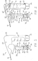
- the system 20 comprises a container 30 that is configured to hold a therapeutic agent 38, and further comprises at least one pressure source 68 that is configured to be placed in selective fluid communication with at least a portion of the container 30, to deliver the therapeutic agent 38 through a catheter 90 to a target site within the patient, as explained more fully below.
- the system 20 further comprises a housing 22, which is suitable for securely holding, engaging and/or covering the container 30, pressure source 68, catheter 90, and other components described below.
- the housing 22 comprises an upright section 24 that may be grasped by a user and a section 25 for engaging the container 30.
- Actuators 26 and 28 may be engaged by a user and selectively operated to perform the functions described below.
- the container 30 may comprise any suitable size and shape for holding the therapeutic agent 38.
- the container 30 comprises a generally tube-shaped configuration having a first region 31, a second region 32, and a reservoir 33 defined by an interior of the container 30.
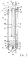
- a platform 35 may be positioned within the container 30 above a curved end region 34, as best seen in FIG. 3 .
- the platform 35 preferably forms a substantially fluid tight seal with an inner surface of the container 30, thereby preventing the therapeutic agent 38 that is disposed in the reservoir 33 from reaching an inner portion of the curved end region 34, as shown in FIG. 3 .
- the platform 35 comprises an opening 36 though which fluid from the pressure source 68 is directed via a u-shaped tube 37 disposed within the curved end region 34, as shown in FIG. 3 and explained in further detail below.
- the container 30 may further comprise an inlet tube 40, an outlet tube 50, and a cap 60, wherein the cap 60 is configured to be secured to the first region 31 of the container 30, as depicted in FIG. 3 .
- the inlet tube 40 has first and second ends 41 and 42 with a lumen 43 extending therebetween, while the outlet tube 50 has first and second ends 51 and 52 with a lumen 53 extending therebetween.
- the first end 41 of the inlet tube 40 is placed in fluid communication with an inlet port 61 formed in the cap 60, while the first end 51 of the outlet tube 50 is placed in fluid communication with an outlet port 62 formed in the cap 60, as shown in FIG. 3 .
- the second end 42 of the inlet tube 40 extends towards the platform 35, and may be coupled to an adapter 44, which may be integral with the platform 35 or secured thereto.
- the adapter 44 places the second end 42 of the inlet tube 40 in fluid communication with a first end 45 of the u-shaped tube 37, which is disposed within the curved end region 34, as shown in FIG. 3 .
- a second end 46 of the u-shaped tube 37 is in fluid communication with the opening 36 in the platform 35.
- fluid passed through the inlet port 61 of the cap 60 is directed through the inlet tube 40, through the u-shaped tube 37, and into the reservoir 33 via the opening 36.
- the u-shaped tube 37 effectively changes the direction of the fluid flow by approximately 180 degrees, such that the fluid originally flows in a direction from the first region 31 of the container 30 towards the second region 32, and then from the second region 32 back towards the first region 31.
- the first region 31 of the container 30 is disposed vertically above the second region 32 of the container 30 during use, however, it is possible to have different placements of the first and second regions 31 and 32 relative to one another, such that they are disposed at least partially horizontally adjacent to one another.
- the second end 52 of the outlet tube 50 may terminate a predetermined distance above the platform 35, as shown in FIGS. 1-3 . While the second end 52 is shown relatively close to the platform 35 in this embodiment, any suitable predetermined distance may be provided. For example, the outlet tube 50 may be shorter in length, e.g., about half of the length shown in FIGS. 1-3 , and therefore, the second end 52 may be spaced apart further from the platform 35. In a presently preferred embodiment, the second end 52 of the outlet tube 50 is radially aligned with the opening 36 in the platform 35, as depicted in FIGS. 1-3 .
- the fluid and the therapeutic agent 38 within the reservoir 33 may be directed through the outlet tube 50, through the outlet port 62, and towards a target site.
- the outlet tube 50 may be omitted and the therapeutic agent 38 may flow directly from the reservoir 33 into the outlet port 62.
- Other variations on the container 30 and outlet port 62 may be found in U.S. patent application Ser. No. 12/633,027, filed Dec. 8, 2009 .
- the cap 60 may comprise any suitable configuration for sealingly engaging the first region 31 of the container 30.
- an O-ring 65 is held in place around a circumference of the cap 60 to hold the therapeutic agent 38 within the reservoir 33.
- the cap 60 may comprise one or more flanges 63 that permit a secure, removable engagement with a complementary internal region of the section 25 of the housing 22. For example, by rotating the container 30, the flange 63 of the cap 60 may lock in place within the section 25.
- the inlet and outlet tubes 40 and 50 may be held in place within the container 30 by one or more support members.
- a first support member 48 is secured around the inlet and outlet tubes 40 and 50 near their respective first ends 41 and 51, as shown in FIG. 3 .
- the first support member 48 may be permanently secured around the inlet and outlet tubes 40 and 50, and may maintain a desired spacing between the tubes.
- a second support member 49 may be secured around the inlet and outlet tubes 40 and 50 near their respective second ends 42 and 52, as shown in FIGS. 1-3 .
- greater or fewer support members may be provided to hold the inlet and outlet tubes 40 and 50 in a desired orientation within the container 30.
- the second support member 49 may be omitted and just the first support member 48 may be provided, or greater than two support members may be used.
- the inlet and outlet tubes 40 and 50 may be securely coupled to the first support member 48, the second support member 49, the platform 35 and the u-shaped tube 37.
- the platform 35 may be advanced towards the second region 32 of the empty container 30 until the platform rests on a step 47 above the curved end region 35 of the container 30, as shown in FIG. 3 .
- a desired quantity of the therapeutic agent 38 may be loaded through slits 57 formed adjacent to, or within, the first support member 48, as depicted in FIG. 3 .
- the container 30 also may comprise measurement indicia 39, which allow a user to determine a quantity of the therapeutic agent 38 that is loaded within the reservoir 33 as measured, for example, from the top of the platform 35.
- the cap 60 may be securely coupled to the first region 31 of the container 30, and the container 30 then is securely coupled to the section 25 of the handle 22 as described above.
- the pressure source 68 may comprise one or more components capable of producing or furnishing a fluid having a desired pressure.
- the pressure source 68 may comprise a pressurized fluid, such as a liquid or gas.
- the pressure source 68 may comprise a pressurized fluid cartridge of a selected gas or liquid, such as carbon dioxide, nitrogen, or any other suitable gas or liquid that may be compatible with the human body.
- the pressurized fluid cartridge may contain the gas or liquid at a relatively high, first predetermined pressure, for example, around 12MPascal (1,800 psi) inside of the cartridge.
- the pressure source 68 optionally may comprise one or more commercially available components.
- the pressure source 68 therefore may comprise original or retrofitted components capable of providing a fluid or gas at an original pressure.
- the fluid may flow from the pressure source 68 through a pressure regulator, such as regulator valve 70 having a pressure outlet 72, as depicted in FIG. 2 , which may reduce the pressure to a lower, second predetermined pressure.
- a pressure regulator such as regulator valve 70 having a pressure outlet 72, as depicted in FIG. 2 , which may reduce the pressure to a lower, second predetermined pressure.
- the second predetermined pressure may be in the range of about 30 to about 80 psi, although any suitable pressure may be provided for the purposes described below.
- the actuator 26 may be actuated to release the fluid from the pressure source 68.
- a user may rotate the actuator 26, which translates into linear motion via a threaded engagement 29 between the actuator 26 and the housing 22, as shown in FIG. 2 .
- the regulator valve 70 may pierce through a seal of the pressure cartridge to release the high pressure fluid. After the regulator valve 70 reduces the pressure, the fluid may flow from the pressure outlet 72 to an actuation valve 80 via tubing 75.
- the actuation valve 80 comprises an inlet port 81 and an outlet port 82.
- the actuator 28, which may be in the form of a depressible button, may selectively engage the actuation valve 80 to selectively permit fluid to pass from the inlet port 81 to the outlet port 82.
- the actuation valve 80 may comprise a piston having a bore formed therein that permits fluid flow towards the outlet port 82 when the actuator 28 engages the actuation valve 80. Fluid that flows through the outlet port 82 is directed into the inlet port 61 of the cap 60 via tubing 85, and subsequently is directed into the container 30, as explained above. It will be appreciated that any suitable coupling mechanisms may be employed to secure the various pieces of tubing to the various valves and ports.
- the system 20 further may comprise one or more tube members for delivering the therapeutic agent 38 to a target site.
- the tube member may comprise a catheter 90 having a proximal end that may be placed in fluid communication with the outlet port 62.
- the catheter 90 further comprises a distal end that may facilitate delivery of the therapeutic agent 38 to a target site.
- the catheter 90 may comprise a flexible, tubular member that may be formed from one or more semi-rigid polymers.
- the catheter may be manufactured from polyurethane, polyethylene, tetrafluoroethylene, polytetrafluoroethylene, fluorinated ethylene propylene, nylon, PEBAX or the like. Further details of a suitable tube member are described in U.S. patent Ser. No.
- a needle suitable for penetrating tissue may be coupled to the distal end of the catheter 90 to form a sharp, distal region configured to pierce through a portion of a patient's tissue, or through a lumen wall to perform a translumenal procedure.
- the distal end of the catheter 90 may be positioned in relatively close proximity to the target site.
- the catheter 90 may be advanced to the target site using an open technique, a laparoscopic technique, an intraluminal technique, using a gastroenterology technique through the mouth, colon, or using any other suitable technique.
- the catheter 90 may comprise one or more markers configured to be visualized under fluoroscopy or other imaging techniques to facilitate location of the distal end of the catheter 90. If desired, the catheter 90 may be advanced through a working lumen of an endoscope.
- the pressure source 68 may be actuated by engaging the actuator 26.
- the pressurized fluid may flow from the pressure source 68 through a regulator valve 70 and be brought to a desired pressure and rate.
- the fluid then flows through the tubing 75, and when the actuator 28 is selectively depressed, the fluid flows through the valve 80 and through the tubing 85 towards the container 30.
- the fluid is then directed through the inlet port 62, through the inlet tube 40 within the container 30, and through the u-shaped tube 37. At this point, the u-shaped tube effectively changes the direction of the fluid flow.
- Regulated fluid then flows through the opening 36 in the platform 35 and urges the therapeutic agent 38 through the outlet tube 50.
- the fluid and the therapeutic agent 38 then exit through the first end 51 of the outlet tube 50, through the outlet port 62 of the cap 60, and through the catheter 90, thereby delivering the therapeutic agent 38 to the target site at a desired pressure.
- a control mechanism may be coupled to the system 20 to variably permit fluid flow into and/or out of the container 30 at a desired time interval, for example, a predetermined quantity of fluid per second.
- pressurized fluid may periodically flow into or out of the container 30 periodically to deliver the therapeutic agent 38 to a target site at a predetermined interval or otherwise periodic basis.
- the system 20 may be used to deliver the therapeutic agent 38 in a wide range of procedures and the therapeutic agent 38 may be chosen to perform a desired function upon ejection from the distal end of the catheter 90.
- the provision of the therapeutic agent 38 may be used for providing hemostasis, closing perforations, performing lithotripsy, treating tumors and cancers, treat renal dialysis fistulae stenosis, vascular graft stenosis, and the like.
- the therapeutic agent 38 can be delivered during procedures such as coronary artery angioplasty, renal artery angioplasty and carotid artery surgery, or may be used generally for treating various other cardiovascular, respiratory, gastroenterology or other conditions.
- the above-mentioned systems also may be used in transvaginal, umbilical, nasal, and bronchial/lung related applications.
- thrombin, epinephrine, or a sclerosant may be provided to reduce localized bleeding.
- a fibrin sealant may be delivered to a localized lesion.
- the relatively high pressure of the fluid and therapeutic agent by itself, may act as a mechanical tamponade by providing a compressive force, thereby reducing the time needed to achieve hemostasis.
- the therapeutic agent 38 may be selected to perform one or more desired biological functions, for example, promoting the ingrowth of tissue from the interior wall of a body vessel, or alternatively, to mitigate or prevent undesired conditions in the vessel wall, such as restenosis. Many other types of therapeutic agents 38 may be used in conjunction with the system 20.
- the therapeutic agent 38 may be delivered in any suitable form.
- the therapeutic agent 38 may comprise a powder, liquid, gel, aerosol, or other substance.
- the pressure source 68 may facilitate delivery of the therapeutic agent 38 in any one of these forms.
- the therapeutic agent 38 employed also may comprise an antithrombogenic bioactive agent, e.g., any bioactive agent that inhibits or prevents thrombus formation within a body vessel.
- antithrombotic bioactive agents include anticoagulants, antiplatelets, and fibrinolytics.
- Anticoagulants are bioactive materials which act on any of the factors, cofactors, activated factors, or activated cofactors in the biochemical cascade and inhibit the synthesis of fibrin.
- Antiplatelet bioactive agents inhibit the adhesion, activation, and aggregation of platelets, which are key components of thrombi and play an important role in thrombosis.
- Fibrinolytic bioactive agents enhance the fibrinolytic cascade or otherwise aid in dissolution of a thrombus.
- antithrombotics include but are not limited to anticoagulants such as thrombin, Factor Xa, Factor VIIa and tissue factor inhibitors; antiplatelets such as glycoprotein IIb/IIIa, thromboxane A2, ADP-induced glycoprotein IIb/IIIa, and phosphodiesterase inhibitors; and fibrinolytics such as plasminogen activators, thrombin activatable fibrinolysis inhibitor (TAFI) inhibitors, and other enzymes which cleave fibrin.
- anticoagulants such as thrombin, Factor Xa, Factor VIIa and tissue factor inhibitors
- antiplatelets such as glycoprotein IIb/IIIa, thromboxane A2, ADP-induced glycoprotein IIb/IIIa, and phosphodiesterase inhibitors
- fibrinolytics such as plasminogen activators, thrombin activatable fibrinolysis inhibitor (TAFI) inhibitors, and other enzymes which cleave fibrin.
- TAFI thrombin activatable fibr
- the therapeutic agent 38 may include thrombolytic agents used to dissolve blood clots that may adversely affect blood flow in body vessels.
- a thrombolytic agent is any therapeutic agent that either digests fibrin fibers directly or activates the natural mechanisms for doing so. Examples of commercial thrombolytics, with the corresponding active agent in parenthesis, include, but are not limited to, Abbokinase (urokinase), Abbokinase Open-Cath (urokinase), Activase (alteplase, recombinant), Eminase (anitstreplase), Retavase (reteplase, recombinant), and Streptase (streptokinase). Other commonly used names are anisoylated plasminogen-streptokinase activator complex; APSAC; tissue-type plasminogen activator (recombinant); t-PA; rt-PA.
- the therapeutic agent 38 comprises a hemostasis powder manufactured by TraumaCure, Inc. of Bethesda, MD.
- TraumaCure, Inc. of Bethesda, MD.
- numerous other suitable therapeutic agents may be used in conjunction with the system 20 and delivered through the catheter 90.
- the system 20 permits localized delivery of a desired quantity of the therapeutic agent 38 at a desired, regulated pressure. Since the distal end of the catheter 90 may be placed in relatively close proximity to a target site, the system 20 provides significant advantages over therapeutic agents delivered orally or through an IV system and may reduce accumulation of the therapeutic agent 38 in healthy tissues, thereby reducing side effects. Moreover, the delivery of the therapeutic agent 38 to the target site is performed in a relatively fast manner due to the relatively high pressure of the fluid, thereby providing a prompt delivery to the target site compared to previous devices.
- the system 20 advantageously may be used to both perforate tissue at or near a target site, then deliver the therapeutic agent 38 at a desired pressure in the manner described above.
- the needle may comprise an endoscopic ultrasound (EUS) needle.
- EUS endoscopic ultrasound
- a sharpened tip of the needle may be capable of puncturing through an organ or a gastrointestinal wall or tissue, so that the therapeutic agent 38 may be delivered at a predetermined pressure in various bodily locations that may be otherwise difficult to access.
- One or more delivery vehicles such as an endoscope or sheath, may be employed to deliver the catheter 90 to a target site, particularly if the distal end of the catheter 90 comprises the optional needle.
- the alternative system 20' comprises an inlet tube 40' having a J-shaped curvature 93 that causes a second end 42' of the inlet tube 40' to direct fluid flow in a substantially opposing direction relative to the first end 41 of the inlet tube 40'.
- fluid from the pressure source 68 flows through the first end 41 of the inlet tube 40', through the J-shaped curvature 93 and exits the second end 42', thereby directing the therapeutic agent 38 (not shown in FIG. 4 ) into the outlet tube 50 for delivery to a target site via the catheter 90, as generally explained above.
- the platform 35 may be omitted and the therapeutic agent 38 may settle on a lower region of the reservoir 33.
- Measurement indicia 39' may measure a quantity of the therapeutic agent 38 from the lower region of the reservoir 33.
- a filter may cover the second end 52 of the outlet tube 50.
- the filter may be sized to ensure that only relatively small particles of the therapeutic agent 38 enter into the outlet tube 50, thereby reducing the risk of clogging. If relatively large particles become present in the reservoir 33, the fluid from the pressure source 68 entering into the container may break up the larger particles until they are small enough to pass through the filter and into the outlet tube 50.
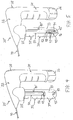
- the alternative system 20" comprises an inlet tube 40" having a curvature 94 that directs fluid into a flow assembly 95.
- the flow assembly 95 has an inlet 96 comprising at least one bore configured for fluid communication with the second end 42" of the inlet tube 40".
- the flow assembly 95 further comprises an outlet 98 that is coupled to, and in fluid communication with, the second end 52 of the outlet tube 50.
- At least one opening 97 is formed in a lateral surface of the flow assembly 95 between the inlet 96 and the outlet 98, wherein the openings 97 are sized to permit suctioning of the therapeutic agent 38 therethrough.
- the openings 97 may comprise slits, as generally depicted, or alternatively circular bores or other shapes.
- fluid from the pressure source 68 flows through the first end 41 of the inlet tube 40", through the curvature 94 and the second end 42", and into the flow assembly 95 via the inlet 96.
- the fluid thereby directs the therapeutic agent 38 within the reservoir 33 into the outlet tube 50, via the openings 97, for delivery to a target site via the catheter 90.
- a localized low pressure system will be provided in the vicinity of the openings 97 in accordance with Bernoulli's principle of fluid dynamics.
- the low pressure system formed by the presence of the pressurized fluid passing through the flow assembly 95 will form a strong suction force when it passes by the openings 97.
- the therapeutic agent 38 may be suctioned out of the reservoir 33, through the openings 97 and through the outlet 98 and outlet tube 50.
- the slits or other openings may be sized to ensure that only relatively small particles of the therapeutic agent 38 enter into the outlet tube 50, thereby reducing the risk of clogging.
- the system 120 comprises a housing 122, which is suitable for securely holding, engaging and/or covering the components described below.
- a user may hold the system 120 during use by grasping an upright support 125 and/or an outer surface of a container 130.
- Actuators 126 and 128, which are similar to actuators 26 and 28 above, may be engaged by a user and actuated to perform the functions described below.
- the container 130 may comprise any suitable size and shape for holding the therapeutic agent 38 described above (not shown in FIGS. 6-8 for illustrative purposes).
- the container 130 has a first region 131 and a second region 132.
- An upper cap 160 may securely engage the first region 131, while a lower cap 165 may securely engage the second region 132, thereby holding the therapeutic agent 38 within a reservoir 133.
- Measurement indicia 139 are provided to determine a quantity of the therapeutic agent 38 within the reservoir 133.
- an outlet tube 150 having first and second ends 151 and 152 is positioned within the container 130.
- the second end 152 of the tube 150 terminates a predetermined distance above an upper surface 168 of the lower cap 165, as shown in FIGS. 6-8 .
- the second end 152 of the outlet tube 150 may be aligned with an opening 166 in the upper surface 168 of the lower cap 165, as depicted in FIGS. 6 and 8 .
- the system 120 further comprises at least one linkage 177 having first and second ends 178 and 179.
- the first end 178 of the linkage 177 is coupled to the actuator 128, while the second end 179 of the linkage 177 is coupled to the valve 80. Accordingly, when the actuator 128 is depressed, the valve 80 may be selectively actuated.
- the container 130 may comprise a groove 137, as best seen in FIG. 8 , for accommodating the linkage 177.
- the upper and lower caps 160 and 165 also may comprise corresponding grooves 162 and 167, respectively, for accommodating the linkage 177. It will be apparent that any number of linkages may be used, and their positioning within the housing 122 may be varied, as needed, to impart a desired motion from the actuator 128 to selectively actuate the valve 80.
- an orientation device 193 may be used for indicating a vertical orientation of the container 130.
- the orientation device 193 may be formed integrally with the housing 122, or coupled to an exterior surface of the housing 122.
- the orientation device 193 may comprise a captive liquid, ball, arrow or other member, or an electronic display, which provides an indication of the vertical orientation of the container 130. Therefore, when the system 120 is held in a user's hand, the user may determine whether the container 130 is oriented vertically, which may enhance flow of the therapeutic agent 38 and other functionality.
- the orientation device 193 shown in FIGS. 6-7 also may be used in the embodiments of FIGS. 1-5 and 8-9 .
- the pressure source 68 may be actuated by engaging the actuator 126.
- the pressurized fluid may flow through a regulator valve 70 and be brought to a desired pressure and rate.
- the fluid then flows through the tubing 75, and when the actuator 28 is selectively actuated, the fluid flows through the valve 80 and through the tubing 85 towards the container 130.
- Regulated fluid then flows through the opening 166 within the lower cap 165, into the reservoir 133, and urges the therapeutic agent 38 through the outlet tube 150 in a direction from the second end 152 towards the first end 151.
- the fluid and the therapeutic agent 38 then exit through the first end 151 of the outlet tube 150, through the opening 161 of the upper cap 160, and through the catheter 90, which is in fluid communication with the opening 161. Accordingly, the therapeutic agent 38 is delivered to the target site at a desired interval and pressure.
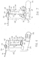
- the system 220 comprises a housing 222, which is suitable for securely holding, engaging and/or covering the components described below.
- a user may hold the system 220 during use by grasping a generally upright support 225.
- Actuators 226 and 228, which are similar to actuators 26 and 28 above, may be engaged by a user and actuated to perform the functions described below.
- an alternative container 230 comprises a reservoir 233 for holding the therapeutic agent 38 described above (not shown in FIGS. 9-10 for illustrative purposes).
- the container 230 has a first region 231 and a second region 232.
- Measurement indicia 239 are provided to determine a quantity of the therapeutic agent 38 within the reservoir 233.
- the second region 232 of the container 230 is securely coupled to a lower cap 234.
- the lower cap 234 comprises an inlet port 243, which is in fluid communication with an opening 236 formed in an upper surface 235 of the lower cap 234.
- a flexible u-shaped tube 237 may be coupled between the inlet port 243 and the opening 236 to provide fluid communication therebetween, as depicted in FIG. 9 .
- the system 220 further comprises at least one linkage 277 having first and second ends 278 and 279.
- the first end 278 of the linkage 277 is coupled to the actuator 228, while the second end 279 of the linkage 277 may be pivotable about an inner element of the housing 222.
- the second end 279 may comprise a bore, as shown in FIG. 9 , which may be secured around a prong (not shown) extending within the housing 222, thereby allowing the second end 279 to pivot around the prong.
- a central region of the linkage 277 may engage the valve 80 to selectively actuate the valve and permit flow therethrough.
- any number of linkages may be used, and their positioning within the housing 222 may be varied, as needed, to impart a desired motion from the actuator 228 to selectively actuate the valve 80.
- Operation of the system 220 is similar to the operation of the system 20 described above.
- the pressure source 68 may be actuated by engaging the actuator 226.
- the pressurized fluid may flow through a regulator valve 70 and be brought to a desired pressure and rate.
- the fluid then flows through the tubing 75, and when the actuator 228 is selectively actuated, the fluid flows through the valve 80 and through the tubing 85.
- Fluid then flows through the inlet port 243, through the u-shaped tube positioned within the lower cap 234, through the opening 236 and into the reservoir 233. Fluid entering the reservoir 233 then urges the therapeutic agent 38 through an outlet port 261 at the first region 231 of the container 230.
- the first region 231 may comprise a curve or taper 249 to direct the fluid and the therapeutic agent 38 through the opening 261. Subsequently, the fluid and the therapeutic agent 38 flow through the catheter 90, which is in fluid communication with the opening 261, thereby delivering the therapeutic agent 38 to the target site at a desired pressure.
- outlet tubes 50 and 150 of FIGS. 1-5 and 6-8 may be omitted. Therefore, fluid entering into the reservoirs 33 and 133 may urge the therapeutic agent 38 in a direction through outlet port in the caps 60 and 160. A taper or curve may be provided to guide the therapeutic agent 38 out of the containers 30 and 130.
- an outlet tube 350 has a first end 351 that is coupled to an outlet port 362 formed in a distal tip of the housing 322.
- the outlet port 362 has proximal and distal regions 363 and 364, whereby the proximal region 363 is configured to securely engage the first end 351 of the outlet tube 350, and the distal region 364 is configured to be coupled to the catheter 90 of FIGS. 1-2 .
- a luer-type connection may be provided.
- a physician may easily exchange the catheter 90 during a procedure, for example, if the catheter 90 becomes occluded.
- FIG. 11 depicts an alternative connection of a container 330 to the housing 322.
- the container 330 is similar to the container 30 described above, but in the embodiment of FIG. 11 , a cap of the container 330 comprises a flanged region 363 having an O-ring 365 disposed therein, wherein the flanged region 363 is configured to be secured between upper and lower internal stops 388 and 389 of the housing 322.
- the flanged region 363 of the cap may be held in place without the ability to be removed, thereby permanently securing the container 330 to the handle 322 and eliminating the opportunity for the container 330 to be reusable.
- other features of the cap of FIG. 11 that are not shown may be provided in a manner similar to the cap 60 of FIG. 3 , such as the inlet port 61.
- an alternative actuator 426 is provided, which is generally similar to the actuator 26 of FIGS. 1-2 , with a main exception that there is provided a lower handle portion 427 and a generally upright portion 428 that extends vertically within the housing 422 and upwards beyond a portion of a regulator valve 70.
- An upper region of the generally upright portion 428 comprises threading 429, which is configured to engage threading on an outer surface of the regulator valve 70.
- a user may rotate the lower handle portion 427 of the actuator 426, which translates into linear motion relative to the regulator valve 470 via the threaded engagement 429.
- the regulator valve 470 may pierce through a seal of the pressure cartridge to release the high pressure fluid.
- the fluid may flow from the pressure outlet 72 to an actuation valve 80 via tubing 75, in the manner explained in FIG. 2 above.
- a safety ledge or interference may be provided on the housing 422 to prevent the actuator 426 from becoming disengaged, which could otherwise allow the pressure cartridge to be ejected from the device.
Landscapes
- Health & Medical Sciences (AREA)
- Engineering & Computer Science (AREA)
- Life Sciences & Earth Sciences (AREA)
- Veterinary Medicine (AREA)
- Animal Behavior & Ethology (AREA)
- Biomedical Technology (AREA)
- Heart & Thoracic Surgery (AREA)
- Public Health (AREA)
- General Health & Medical Sciences (AREA)
- Hematology (AREA)
- Anesthesiology (AREA)
- Medical Informatics (AREA)
- Dermatology (AREA)
- Vascular Medicine (AREA)
- Surgery (AREA)
- Nuclear Medicine, Radiotherapy & Molecular Imaging (AREA)
- Molecular Biology (AREA)
- Infusion, Injection, And Reservoir Apparatuses (AREA)
Priority Applications (2)
| Application Number | Priority Date | Filing Date | Title |
|---|---|---|---|
| EP16180809.2A EP3150240B1 (en) | 2009-05-29 | 2010-05-27 | Systems and methods for delivering therapeutic agents |
| DK16180809.2T DK3150240T3 (da) | 2009-05-29 | 2010-05-27 | Systemer og fremgangsmåder til fremføring af terapeutiske midler |
Applications Claiming Priority (2)
| Application Number | Priority Date | Filing Date | Title |
|---|---|---|---|
| US18246309P | 2009-05-29 | 2009-05-29 | |
| PCT/US2010/036381 WO2010138703A1 (en) | 2009-05-29 | 2010-05-27 | Systems and methods for delivering therapeutic agents |
Related Child Applications (2)
| Application Number | Title | Priority Date | Filing Date |
|---|---|---|---|
| EP16180809.2A Division-Into EP3150240B1 (en) | 2009-05-29 | 2010-05-27 | Systems and methods for delivering therapeutic agents |
| EP16180809.2A Division EP3150240B1 (en) | 2009-05-29 | 2010-05-27 | Systems and methods for delivering therapeutic agents |
Publications (2)
| Publication Number | Publication Date |
|---|---|
| EP2435114A1 EP2435114A1 (en) | 2012-04-04 |
| EP2435114B1 true EP2435114B1 (en) | 2016-08-31 |
Family
ID=42342773
Family Applications (2)
| Application Number | Title | Priority Date | Filing Date |
|---|---|---|---|
| EP10722265.5A Active EP2435114B1 (en) | 2009-05-29 | 2010-05-27 | Systems for delivering therapeutic agents |
| EP16180809.2A Active EP3150240B1 (en) | 2009-05-29 | 2010-05-27 | Systems and methods for delivering therapeutic agents |
Family Applications After (1)
| Application Number | Title | Priority Date | Filing Date |
|---|---|---|---|
| EP16180809.2A Active EP3150240B1 (en) | 2009-05-29 | 2010-05-27 | Systems and methods for delivering therapeutic agents |
Country Status (7)
| Country | Link |
|---|---|
| US (2) | US8118777B2 (enExample) |
| EP (2) | EP2435114B1 (enExample) |
| JP (2) | JP5670439B2 (enExample) |
| AU (1) | AU2010253997B2 (enExample) |
| CA (1) | CA2763135C (enExample) |
| DK (2) | DK3150240T3 (enExample) |
| WO (1) | WO2010138703A1 (enExample) |
Cited By (2)
| Publication number | Priority date | Publication date | Assignee | Title |
|---|---|---|---|---|
| CN110538365A (zh) * | 2019-08-27 | 2019-12-06 | 佳木斯大学 | 一种儿科呼吸道内科雾化给药装置 |
| US12496429B2 (en) | 2022-10-18 | 2025-12-16 | Cook Medical Technologies Llc | Systems and methods for delivering pressurized fluid to a target site alone or in conjunction with therapeutic agents |
Families Citing this family (58)
| Publication number | Priority date | Publication date | Assignee | Title |
|---|---|---|---|---|
| US11167058B2 (en) | 2005-02-15 | 2021-11-09 | Virginia Commonwealth University | Hemostasis of wound having high pressure blood flow |
| US7604819B2 (en) | 2006-05-26 | 2009-10-20 | Z-Medica Corporation | Clay-based hemostatic agents and devices for the delivery thereof |
| US9101744B2 (en) | 2009-05-29 | 2015-08-11 | Cook Medical Technologies Llc | Systems and methods for delivering therapeutic agents |
| US9205207B2 (en) * | 2010-01-15 | 2015-12-08 | Xin Ji | Internal dry powder delivery system and method thereof |
| US8858969B2 (en) | 2010-09-22 | 2014-10-14 | Z-Medica, Llc | Hemostatic compositions, devices, and methods |
| US8870756B2 (en) * | 2010-10-08 | 2014-10-28 | ERBE-USA, Inc. | Hybrid apparatus for fluid supply for endoscopic irrigation and lens cleaning |
| US20120135526A1 (en) * | 2010-11-23 | 2012-05-31 | Kenneth Greenberg | Low-pressure biolistic barrels |
| US9314568B2 (en) | 2011-02-11 | 2016-04-19 | Lifecell Corporation | Devices and methods for tissue transfer |
| RU2013151160A (ru) * | 2011-04-19 | 2015-05-27 | ИНВИЗИДЕРМ ЭлЭлСи | Способ создания веществ, перенасыщенных газом, устройство трансдермальной доставки и его использование |
| BR112013027010A2 (pt) * | 2011-04-19 | 2016-12-27 | Invisiderm Llc | método de produzir substâncias com gás supersaturado, dispositivo para sua entrega trasdérmica, e seus usos |
| CN103619265B (zh) * | 2011-04-27 | 2016-04-06 | 比奥马普公司 | 生物医学止血粉末分配器 |
| US10130800B2 (en) * | 2012-01-27 | 2018-11-20 | Invisiderm, Llc | Method of producing substances with supersaturated gas, transdermal delivery device thereof, and uses thereof |
| USD857882S1 (en) | 2012-02-10 | 2019-08-27 | Lifecell Corporation | Tissue transfer apparatus |
| CA2865349C (en) * | 2012-03-06 | 2021-07-06 | Ferrosan Medical Devices A/S | Pressurized container containing haemostatic paste |
| EP3412320A1 (en) | 2012-06-22 | 2018-12-12 | Z-Medica, LLC | Hemostatic devices |
| US20140114248A1 (en) * | 2012-10-24 | 2014-04-24 | Nuance Designs, LLC | Power pack for an autoinjector |
| US9358339B2 (en) * | 2012-12-14 | 2016-06-07 | Bay Genomics, LLC | Particle based biologically active molecule delivery systems |
| WO2014099662A1 (en) * | 2012-12-21 | 2014-06-26 | Cook Medical Technologies Llc | Systems and methods for delivering therapeutic agents |
| CN103041499A (zh) * | 2013-01-18 | 2013-04-17 | 宁波市镇海怡福莱文化创意有限公司 | 一种气动喷粉器 |
| US11931227B2 (en) | 2013-03-15 | 2024-03-19 | Cook Medical Technologies Llc | Bimodal treatment methods and compositions for gastrointestinal lesions with active bleeding |
| US9867931B2 (en) | 2013-10-02 | 2018-01-16 | Cook Medical Technologies Llc | Therapeutic agents for delivery using a catheter and pressure source |
| WO2015062420A1 (zh) * | 2013-10-28 | 2015-05-07 | 浙江三创生物科技有限公司 | 粉末喷射方法及其装置 |
| CA2965509C (en) | 2014-10-24 | 2023-03-14 | Avectas Limited | Delivery across cell plasma membranes |
| CN107530502B (zh) | 2015-02-20 | 2021-01-15 | 里珍纳龙药品有限公司 | 注射器系统、活塞密封系统、塞子系统 |
| PL3295993T3 (pl) * | 2015-05-15 | 2020-04-30 | Beautygun S.L. | Urządzenie do podawania produktu kosmetycznego, odpowiedni sposób i pojemnik |
| US11827899B2 (en) | 2015-12-30 | 2023-11-28 | Avectas Limited | Vector-free delivery of gene editing proteins and compositions to cells and tissues |
| US10441761B2 (en) | 2016-07-01 | 2019-10-15 | Boston Scientific Scimed, Inc. | Delivery devices and methods |
| WO2018059642A2 (en) | 2016-09-28 | 2018-04-05 | Ambu A/S | An endoscope adapted for facilitating bal procedures |
| CN115591066A (zh) | 2017-01-10 | 2023-01-13 | 波士顿科学国际有限公司(Us) | 用于输送粉末药剂的装置和方法 |
| WO2018202267A1 (en) | 2017-05-02 | 2018-11-08 | Ambu A/S | An endoscope |
| US11602761B1 (en) * | 2017-07-17 | 2023-03-14 | Joseph D. Osborne | Blower-attached product applicator, and method for dispensing a product into a moving airstream |
| US10786596B2 (en) | 2018-01-12 | 2020-09-29 | Boston Scientific Scimed, Inc. | Powder for achieving hemostasis |
| US11766546B2 (en) | 2018-01-31 | 2023-09-26 | Boston Scientific Scimed, Inc. | Apparatuses and methods for delivering powdered agents |
| CN117547720A (zh) * | 2018-10-02 | 2024-02-13 | 波士顿科学国际有限公司 | 用于流体化和输送粉状剂的装置 |
| AU2019352968B2 (en) | 2018-10-02 | 2024-10-31 | Boston Scientific Scimed, Inc. | Devices for fluidization and delivering a powdered agent |
| US20210106717A1 (en) * | 2019-10-10 | 2021-04-15 | Cook Medical Technologies Llc | Bonded powders for the treatment of bodily lesions |
| CN110538351A (zh) * | 2019-10-21 | 2019-12-06 | 青州市中医院 | 一种用于去除上呼吸道中粘液的喷雾器 |
| EP4017338B1 (en) | 2019-12-03 | 2024-01-31 | Boston Scientific Scimed, Inc. | Medical devices for agent delivery |
| WO2021113324A1 (en) | 2019-12-03 | 2021-06-10 | Boston Scientific Scimed, Inc. | Devices and methods for delivering powdered agents |
| EP4417233A3 (en) * | 2019-12-03 | 2024-10-23 | Boston Scientific Scimed, Inc. | Medical devices for agent delivery |
| CN121102700A (zh) | 2019-12-03 | 2025-12-12 | 波士顿科学国际有限公司 | 药剂施用医疗装置 |
| CN114845644A (zh) | 2019-12-20 | 2022-08-02 | 波士顿科学国际有限公司 | 药剂输送装置 |
| CN119971275A (zh) | 2020-01-06 | 2025-05-13 | 波士顿科学国际有限公司 | 用于输送粉末状药剂的装置 |
| US12102749B2 (en) | 2020-01-06 | 2024-10-01 | Boston Scientific Scimed, Inc. | Agent delivery systems and methods of using the same |
| US12083216B2 (en) | 2020-02-18 | 2024-09-10 | Boston Scientific Scimed, Inc. | Hemostatic compositions and related methods |
| WO2021178239A1 (en) * | 2020-03-06 | 2021-09-10 | Cryoconcepts Lp | Systems and methods for carbon dioxide enhanced delivery of topical substances |
| EP4623837A3 (en) | 2020-03-06 | 2025-12-03 | Boston Scientific Scimed, Inc. | Devices for delivering powdered agents |
| JP7665646B2 (ja) | 2020-03-24 | 2025-04-21 | ボストン サイエンティフィック サイムド,インコーポレイテッド | 薬剤送達システム及びその使用方法 |
| KR20230007378A (ko) | 2020-04-17 | 2023-01-12 | 보스톤 싸이엔티픽 싸이메드 인코포레이티드 | 지혈 조성물 및 관련 방법 |
| WO2021247850A2 (en) | 2020-06-05 | 2021-12-09 | Cook Medical Technologies Llc | Medical scopes for delivering therapeutic agents |
| US20220087688A1 (en) * | 2020-09-22 | 2022-03-24 | Boston Scientific Scimed, Inc. | Pressure release for medical devices |
| KR20230128023A (ko) | 2020-12-31 | 2023-09-01 | 리제너론 파아마슈티컬스, 인크. | 자동 주사기 및 관련 사용 방법 |
| US20230016512A1 (en) | 2021-07-14 | 2023-01-19 | Cook Medical Technologies Llc | Systems and methods for preventing clogging of a delivery system |
| JP7762300B2 (ja) | 2021-10-25 | 2025-10-29 | クック・メディカル・テクノロジーズ・リミテッド・ライアビリティ・カンパニー | 加圧流体を標的部位に単独で又は治療剤と併せて送達するためのシステム |
| US20230211074A1 (en) * | 2022-01-03 | 2023-07-06 | Carefusion 303, Inc. | Intravenous pressure assembly |
| WO2024005555A1 (ko) | 2022-07-01 | 2024-01-04 | 주식회사 리센스메디컬 | 냉각제 공급 장치에 이용되는 혼합 모듈 |
| EP4368123A3 (en) | 2022-10-18 | 2024-07-10 | Cook Medical Technologies LLC | Systems and methods for delivering pressurized fluid to a target site alone or in conjunction with therapeutic agents |
| US20240181177A1 (en) | 2022-12-05 | 2024-06-06 | Cook Medical Technologies Llc | Therapeutic agent delivery systems having improved powder consistency |
Family Cites Families (220)
| Publication number | Priority date | Publication date | Assignee | Title |
|---|---|---|---|---|
| US566411A (en) | 1896-08-25 | Josef schoene | ||
| US39678A (en) | 1863-08-25 | Improvement in powder-injectors | ||
| US460458A (en) | 1891-09-29 | Edward t | ||
| US576437A (en) | 1897-02-02 | Insufflator | ||
| US533489A (en) | 1895-02-05 | Thomas edwin ogram | ||
| US442785A (en) | 1890-12-16 | Atomizer | ||
| US471865A (en) | 1892-03-29 | Vaginal instrument | ||
| US1521396A (en) | 1924-12-30 | By mary v | ||
| US170182A (en) | 1875-11-23 | Improvement in syringes | ||
| CH15244A (de) | 1897-09-24 | 1898-04-30 | August Lauer | Pulverbläser |
| US693587A (en) | 1901-11-11 | 1902-02-18 | Eugenia C Campbell | Insufflator. |
| US881238A (en) | 1902-12-08 | 1908-03-10 | Sayer Hasbrouck | Insufflator. |
| US775985A (en) | 1904-03-18 | 1904-11-29 | Harry L Mckain | Machine for manufacturing artificial flowers, vines, &c. |
| US904149A (en) | 1907-05-31 | 1908-11-17 | Henry Rachmann | Atomizer for scent and other sprays. |
| US938648A (en) | 1909-05-21 | 1909-11-02 | De Vilbiss Mfg Co | Atomizer. |
| US1022601A (en) | 1911-06-16 | 1912-04-09 | Sven S Rumberg | Vaginal syringe. |
| US1145520A (en) | 1913-04-24 | 1915-07-06 | John W Smith | Vaginal powder-sprayer. |
| US1114114A (en) | 1914-04-30 | 1914-10-20 | William E Cochenour | Powder-applicator. |
| US1261503A (en) | 1917-05-02 | 1918-04-02 | Whitall Tatum Co | Atomizer. |
| US1357452A (en) | 1919-05-03 | 1920-11-02 | Burton P Hall | Atomizer or sprayer |
| US1466119A (en) | 1922-09-08 | 1923-08-28 | Charles A Claflin | Conduit member for conducting fluid under pressure |
| US1685280A (en) | 1927-07-16 | 1928-09-25 | Lester L Findley | Powder-placing syringe |
| US1934793A (en) | 1932-03-02 | 1933-11-14 | Crain | Insufflator |
| US2004402A (en) | 1934-04-07 | 1935-06-11 | Conklin John Edward | Atomizer |
| US2151418A (en) | 1937-05-12 | 1939-03-21 | Scott & Bowne | Powder applicator |
| US2223611A (en) | 1939-05-22 | 1940-12-03 | Richard E Gross | Syringe |
| US2390313A (en) | 1939-07-21 | 1945-12-04 | Barr & Stroud Ltd | Gas and liquid mixer |
| US2307986A (en) | 1940-02-15 | 1943-01-12 | Bolte | Insufflator |
| US2519555A (en) | 1945-08-31 | 1950-08-22 | Abbott Lab | Sterile medicament insufflator cartridge and insufflator |
| BE471028A (enExample) | 1946-02-08 | |||
| US2507702A (en) | 1949-03-04 | 1950-05-16 | Abbott Lab | Insufflator |
| US2609155A (en) | 1950-06-15 | 1952-09-02 | Adolph Spreckles | Fishing rod wrapping device |
| US2632444A (en) | 1951-06-14 | 1953-03-24 | Kas John Leo | Pellet injector |
| US2805013A (en) | 1955-04-19 | 1957-09-03 | Comfort John | Garment hanger |
| US2956579A (en) | 1956-08-02 | 1960-10-18 | Electro Way Corp | Dishwashing apparatus |
| US2934314A (en) | 1957-01-18 | 1960-04-26 | Electro Way Corp | Valve |
| US3016895A (en) | 1958-08-01 | 1962-01-16 | Pan American Lab Inc | Injector for subcutaneous implantation of solids |
| US3050261A (en) | 1961-04-24 | 1962-08-21 | Robert Clayton Littlefield | Spray pattern control mechanism for insecticide sprayer |
| NL145136C (enExample) | 1967-07-25 | 1900-01-01 | ||
| US3540444A (en) | 1968-01-15 | 1970-11-17 | Scherer Corp R P | Plastic ampoule for use with hypodermic injector |
| GB1254534A (en) | 1968-03-13 | 1971-11-24 | Wallace Cameron & Company Ltd | Improvements in or relating to treating means for wounds |
| US3506008A (en) | 1968-03-25 | 1970-04-14 | Ortho Pharma Corp | Medical applicator |
| US3632046A (en) | 1968-04-23 | 1972-01-04 | Robert W Hengesbach | Spray nozzle |
| US3599866A (en) | 1968-08-21 | 1971-08-17 | Soilserv Inc | Atomizing spray process and apparatus |
| US3572335A (en) | 1969-01-10 | 1971-03-23 | Ralph R Robinson | Cervical implant method and device |
| US3667465A (en) | 1969-12-08 | 1972-06-06 | Kimberly Clark Co | Applicator tubes for suppositories and the like |
| US3649299A (en) | 1970-03-17 | 1972-03-14 | Jeffrey John Sholl | Method of limiting the depth of penetration of tenderizing and/or flavoring liquids into meat |
| US3647143A (en) | 1970-04-06 | 1972-03-07 | Champion Spark Plug Co | Atomizer |
| US3742955A (en) | 1970-09-29 | 1973-07-03 | Fmc Corp | Fibrous collagen derived product having hemostatic and wound binding properties |
| US3788315A (en) | 1971-04-20 | 1974-01-29 | S Laurens | Disposable cutaneous transjector |
| US3710400A (en) | 1971-08-30 | 1973-01-16 | C Sparks | Graft member grown in a living body |
| DE2144861C2 (de) | 1971-09-08 | 1973-06-20 | Deutsche Nemectron GmbH, 7500 Karlsruhe | Kosmetikgerät zur dermatologischen Behandlung mit einem Wasserdampf-Ozon-Gemisch |
| US3744493A (en) | 1972-01-10 | 1973-07-10 | Syntex Corp | Implanter having an improved cartridge ejector |
| US3762410A (en) | 1972-07-12 | 1973-10-02 | P Bindel | Undulating rectal flushing apparatus |
| US3900022A (en) | 1973-12-10 | 1975-08-19 | Jerrold Widran | Endoscope with uninterrupted flow purging system |
| US4017007A (en) | 1973-12-26 | 1977-04-12 | Ciba-Geigy Corporation | Single dose air pressure operated dispenser |
| US3916896A (en) | 1974-08-05 | 1975-11-04 | Alexander K S Ballard | Portable douche and sitz bath |
| US4040420A (en) | 1976-04-22 | 1977-08-09 | General Dynamics | Packaging and dispensing kit |
| GB1598081A (en) | 1977-02-10 | 1981-09-16 | Allen & Hanburys Ltd | Inhaler device for dispensing medicaments |
| US4174811A (en) | 1977-02-15 | 1979-11-20 | Firma Airotechnik Siegfried Binder Gmbh | Fluid substance sprayer having propellant gas and substance refill |
| US4184258A (en) | 1978-01-30 | 1980-01-22 | The United States Of America As Represented By The Department Of Health, Education And Welfare | Powder blower device |
| US4900303A (en) | 1978-03-10 | 1990-02-13 | Lemelson Jerome H | Dispensing catheter and method |
| US4204645A (en) | 1978-05-17 | 1980-05-27 | Column Corporation | General purpose compression-type sprayer |
| US4204539A (en) | 1979-04-23 | 1980-05-27 | Mathews Van Brugge | Pumps and syringes |
| AT366916B (de) | 1980-04-02 | 1982-05-25 | Immuno Ag | Vorrichtung zur applikation eines gewebeklebstoffes auf basis von menschlichen oder tierischenproteinen |
| DE3024749A1 (de) | 1980-06-30 | 1982-02-04 | Elmont AG, Kreuzlingen | Verfahren und vorrichtung zur erzeugung eines aus einer duese o.dgl. austretenden gas/fluessigkeits-sprays insbesondere fuer die mundhygiene |
| SU978999A2 (ru) | 1981-03-04 | 1982-12-07 | Филиал Ростовского-На-Дону Научно-Исследовательского Института Технологии Машиностроения В Г.Ровно | Устройство дл смазки рабочих поверхностей штампов |
| DE3108918A1 (de) | 1981-03-09 | 1982-09-16 | Beiersdorf Ag, 2000 Hamburg | "spuel-, kuehl- und spruehvorrichtung und deren verwendung" |
| US4539716A (en) | 1981-03-19 | 1985-09-10 | Massachusetts Institute Of Technology | Fabrication of living blood vessels and glandular tissues |
| US4423727A (en) | 1981-04-10 | 1984-01-03 | Jerrold Widran | Continuous flow urological endoscopic apparatus and method of using same |
| ATE20824T1 (de) | 1981-06-25 | 1986-08-15 | Serapharm Gmbh & Co Kg | Angereichertes plasmaderivat zur unterstuetzung von wundverschluss und wundheilung. |
| SE438261B (sv) | 1981-07-08 | 1985-04-15 | Draco Ab | Anvendning i dosinhalator av ett perforerat membran |
| US4516442A (en) | 1982-01-06 | 1985-05-14 | Davis Duane L | Ratchet device |
| US4803977A (en) | 1982-03-25 | 1989-02-14 | Mallinckrodt, Inc. | Method and apparatus for the diagnosis of respiratory diseases and allergies |
| US4578067A (en) | 1982-04-12 | 1986-03-25 | Alcon (Puerto Rico) Inc. | Hemostatic-adhesive, collagen dressing for severed biological surfaces |
| GB8311345D0 (en) | 1983-04-26 | 1983-06-02 | Dobson Park Ind | Oral administration of capsules to animals |
| GB8324265D0 (en) | 1983-09-09 | 1983-10-12 | Devilbiss Co | Miniature spray guns |
| AT379311B (de) | 1984-03-29 | 1985-12-27 | Immuno Ag | Vorrichtung zur applikation eines gewebeklebstoffes |
| US4620847A (en) | 1984-06-01 | 1986-11-04 | Vsesojuzny Nauchno-Issledovatelsky Institut Meditsinskikh Polimerov | Device for administering powdered substances |
| JPS6144825A (ja) | 1984-08-09 | 1986-03-04 | Unitika Ltd | 止血剤 |
| US4872450A (en) | 1984-08-17 | 1989-10-10 | Austad Eric D | Wound dressing and method of forming same |
| US4945050A (en) | 1984-11-13 | 1990-07-31 | Cornell Research Foundation, Inc. | Method for transporting substances into living cells and tissues and apparatus therefor |
| US4798606A (en) | 1985-02-26 | 1989-01-17 | Corvita Corporation | Reinforcing structure for cardiovascular graft |
| AT382783B (de) | 1985-06-20 | 1987-04-10 | Immuno Ag | Vorrichtung zur applikation eines gewebeklebstoffes |
| US5053000A (en) | 1985-11-13 | 1991-10-01 | Imperial Chemical Industries Plc | Ocular treatment |
| US4738740A (en) | 1985-11-21 | 1988-04-19 | Corvita Corporation | Method of forming implantable vascular grafts |
| DK38986A (da) * | 1986-01-27 | 1987-10-10 | Karl Holm | Medicinsk inhalationsapparat |
| DE3613762A1 (de) | 1986-04-23 | 1987-11-05 | Simmet Ludwig Dr Med Vet | Applikationsvorrichtung von injektionsgut, insbesondere zur instrumentellen besamung oder embryouebertragung |
| US4946870A (en) | 1986-06-06 | 1990-08-07 | Union Carbide Chemicals And Plastics Company Inc. | Delivery systems for pharmaceutical or therapeutic actives |
| USH257H (en) | 1986-08-01 | 1987-04-07 | The United States Of America As Represented By The Secretary Of The Army | Dry powder aerosolizer |
| USD303139S (en) | 1986-08-25 | 1989-08-29 | DeVilbiss Corporation | Power washer gun |
| US4738658A (en) | 1986-09-19 | 1988-04-19 | Aries Medical Incorporated | Tapered hemostatic device for use in conjunction with a catheter for alleviating blood leakage and method for using same |
| US5015580A (en) | 1987-07-29 | 1991-05-14 | Agracetus | Particle-mediated transformation of soybean plants and lines |
| US5120657A (en) | 1986-12-05 | 1992-06-09 | Agracetus, Inc. | Apparatus for genetic transformation |
| US4890612A (en) | 1987-02-17 | 1990-01-02 | Kensey Nash Corporation | Device for sealing percutaneous puncture in a vessel |
| US4902278A (en) | 1987-02-18 | 1990-02-20 | Ivac Corporation | Fluid delivery micropump |
| US4994028A (en) | 1987-03-18 | 1991-02-19 | Endocon, Inc. | Injector for inplanting multiple pellet medicaments |
| EP0315656B1 (de) | 1987-05-18 | 1993-07-07 | Disetronic Ag | Infusionsgerät |
| EP0292936B1 (en) | 1987-05-26 | 1996-03-06 | Sumitomo Pharmaceuticals Company, Limited | Device for administering solid preparations |
| US4941880A (en) | 1987-06-19 | 1990-07-17 | Bioject, Inc. | Pre-filled ampule and non-invasive hypodermic injection device assembly |
| DE3725552A1 (de) | 1987-08-01 | 1989-02-09 | Hoechst Ag | Spruehkopf zum applizieren eines mehrkomponentenmaterials mittels gas |
| DE3802158A1 (de) | 1987-08-11 | 1989-02-23 | Hoechst Ag | Vorrichtung zur applikation von implantaten |
| US4790819A (en) | 1987-08-24 | 1988-12-13 | American Cyanamid Company | Fibrin clot delivery device and method |
| US4752466A (en) | 1987-08-31 | 1988-06-21 | Johnson & Johnson Products, Inc. | Thrombin aerosol |
| US4978336A (en) | 1987-09-29 | 1990-12-18 | Hemaedics, Inc. | Biological syringe system |
| US5009637A (en) | 1987-11-16 | 1991-04-23 | Sy-Quest International Limited | Apparatus for hypodermic injection of liquids |
| US5129825A (en) | 1987-12-21 | 1992-07-14 | Discko John Jr | Dental syringe and capsule for use therewith |
| US5179022A (en) | 1988-02-29 | 1993-01-12 | E. I. Du Pont De Nemours & Co. | Biolistic apparatus for delivering substances into cells and tissues in a non-lethal manner |
| US4874368A (en) | 1988-07-25 | 1989-10-17 | Micromedics, Inc. | Fibrin glue delivery system |
| US4902281A (en) | 1988-08-16 | 1990-02-20 | Corus Medical Corporation | Fibrinogen dispensing kit |
| US4929246A (en) | 1988-10-27 | 1990-05-29 | C. R. Bard, Inc. | Method for closing and sealing an artery after removing a catheter |
| US4927410A (en) | 1988-11-18 | 1990-05-22 | University Of South Florida | Method for fabricating prosthesis material |
| US5059187A (en) | 1988-11-30 | 1991-10-22 | Dey Laboratories, Inc. | Method for the cleansing of wounds using an aerosol container having liquid wound cleansing solution |
| CA2013636A1 (en) | 1989-04-06 | 1990-10-06 | Sang I. Han | Disposable pressure wound irrigation device |
| US5061180A (en) | 1989-05-01 | 1991-10-29 | Wiele Gary B | Dental instrument |
| US5226877A (en) | 1989-06-23 | 1993-07-13 | Epstein Gordon H | Method and apparatus for preparing fibrinogen adhesive from whole blood |
| US5116315A (en) | 1989-10-03 | 1992-05-26 | Hemaedics, Inc. | Biological syringe system |
| US5064413A (en) | 1989-11-09 | 1991-11-12 | Bioject, Inc. | Needleless hypodermic injection device |
| US5219328A (en) | 1990-01-03 | 1993-06-15 | Cryolife, Inc. | Fibrin sealant delivery method |
| EP0443227A1 (en) | 1990-02-19 | 1991-08-28 | Ito Corporation | Analytical microsyringe |
| WO1991013595A1 (en) | 1990-03-15 | 1991-09-19 | The United States Of America, As Represented By The Secretary Of The Army | Chemotherapeutic treatment of bacterial infections with an antibiotic encapsulated within a biodegradable polymeric matrix |
| US5021059A (en) | 1990-05-07 | 1991-06-04 | Kensey Nash Corporation | Plug device with pulley for sealing punctures in tissue and methods of use |
| US5204253A (en) | 1990-05-29 | 1993-04-20 | E. I. Du Pont De Nemours And Company | Method and apparatus for introducing biological substances into living cells |
| US5149655A (en) | 1990-06-21 | 1992-09-22 | Agracetus, Inc. | Apparatus for genetic transformation |
| US5391183A (en) | 1990-09-21 | 1995-02-21 | Datascope Investment Corp | Device and method sealing puncture wounds |
| US5141515A (en) | 1990-10-11 | 1992-08-25 | Eberbach Mark A | Apparatus and methods for repairing hernias |
| USD333000S (en) | 1990-11-06 | 1993-02-02 | Devilbiss Health Care, Inc. | Disposable medical atomizer for wound irrigation |
| US5129882A (en) | 1990-12-27 | 1992-07-14 | Novoste Corporation | Wound clotting device and method of using same |
| US5147295A (en) | 1991-01-23 | 1992-09-15 | Ideal Instruments, Inc. | Retractable implanter |
| US5147292A (en) | 1991-02-05 | 1992-09-15 | C. R. Bard, Inc. | Control handle with locking means for surgical irrigation |
| US5176642A (en) | 1991-03-11 | 1993-01-05 | Mectra Labs, Inc. | Vacuum powdered syringe |
| US5310407A (en) | 1991-06-17 | 1994-05-10 | Datascope Investment Corp. | Laparoscopic hemostat delivery system and method for using said system |
| US5538162A (en) | 1991-09-09 | 1996-07-23 | Buhler Ag | Apparatus and method for dosing |
| EP0531758B1 (de) | 1991-09-09 | 1995-10-25 | Buehler Ag | Vorrichtung und Verfahren zum Dosieren von in einem Gas/Fest-Stoff-Strom vorliegenden Feststoff aus einem Wirbelbett |
| IL103238A (en) | 1991-09-25 | 1995-07-31 | Fisons Plc | Pressurised aerosol compositions |
| DK166691D0 (da) | 1991-09-30 | 1991-09-30 | Unes As | Flerkomponentsproejte |
| US5226567A (en) | 1991-10-03 | 1993-07-13 | Dominic A. Sansalone | Garden powder duster |
| US5165604A (en) | 1991-10-03 | 1992-11-24 | Copp Jr William H | Air supply and control assembly for an automatic spray gun |
| US5312333A (en) | 1992-04-03 | 1994-05-17 | United States Surgical Corporation | Endoscopic material delivery device |
| FR2693924B1 (fr) | 1992-07-21 | 1994-09-23 | Sicmo | Pistolet à peinture, basse pression dont la tête de pulvérisation est perfectionnée. |
| US5273531A (en) | 1992-09-21 | 1993-12-28 | Knoepfler Dennis J | Method of applying thrombic powder in laparoscopic procedures |
| WO1994007420A1 (fr) | 1992-09-26 | 1994-04-14 | Juridical Foundation The Chemo-Sero-Therapeutic Research Institute | Applicateur d'adhesif destine a des tissus |
| NZ250214A (en) | 1992-12-23 | 1995-10-26 | Ndm Acquisition Corp | Deep wound dressing and syringe therefor |
| US5292309A (en) | 1993-01-22 | 1994-03-08 | Schneider (Usa) Inc. | Surgical depth measuring instrument and method |
| US5749968A (en) | 1993-03-01 | 1998-05-12 | Focal, Inc. | Device for priming for improved adherence of gels to substrates |
| DE69414558T2 (de) | 1993-03-23 | 1999-07-15 | Focal, Inc., Lexington, Mass. | Gerät und methode für den lokalen auftrag von polymermaterial auf gewebe |
| US5584815A (en) | 1993-04-02 | 1996-12-17 | Eli Lilly And Company | Multi-cartridge medication injection device |
| AU6705894A (en) | 1993-04-20 | 1994-11-08 | Medchem Products, Inc. | Apparatus and method for applying a particulate hemostatic agent to living tissue |
| US5328459A (en) | 1993-05-06 | 1994-07-12 | Laghi Aldo A | Apparatus and method for dispensing and aspirating high viscosity materials |
| DE59400518D1 (de) | 1993-06-16 | 1996-09-26 | White Spot Ag | Vorrichtung zum einbringen von fibrinkleber in einen stichkanal |
| US5398851A (en) | 1993-08-06 | 1995-03-21 | River Medical, Inc. | Liquid delivery device |
| WO1995007053A1 (en) | 1993-09-07 | 1995-03-16 | Invamed, Inc. | Safety shielded, reusable trocar |
| JP2809976B2 (ja) | 1993-10-04 | 1998-10-15 | 株式会社カイゲン | 散粉器及び散粉器に接続する散粉用ノズル |
| US5395326A (en) | 1993-10-20 | 1995-03-07 | Habley Medical Technology Corporation | Pharmaceutical storage and mixing syringe having high pressure assisted discharge |
| WO1995019799A1 (en) | 1994-01-21 | 1995-07-27 | Agracetus, Inc. | Gas driven gene delivery instrument |
| AT400304B (de) | 1994-02-28 | 1995-12-27 | Immuno Ag | Vorrichtung zur applikation eines mehrkomponenten-gewebeklebstoffes |
| US5484403A (en) | 1994-04-05 | 1996-01-16 | Avid Marketing, Inc. | Hypodermic syringe for implanting solid objects |
| US5429278A (en) | 1994-05-09 | 1995-07-04 | Sansalone; Dominic A. | Portable garden powder duster |
| US5520667A (en) | 1994-06-29 | 1996-05-28 | Innovative Surgical Devices Corporation | Methods for bone and other tissue preparation |
| US5605541A (en) | 1994-12-07 | 1997-02-25 | E. R. Squibb And Sons, Inc. | Fibrin sealant applicatoor |
| JPH10512470A (ja) | 1995-01-18 | 1998-12-02 | メドケム プロダクツ,インコーポレーテッド | 組織に止血剤を適用する装置および方法 |
| JPH08206229A (ja) * | 1995-02-02 | 1996-08-13 | Teruo Hoshino | 薬剤投与装置 |
| GB9502879D0 (en) * | 1995-02-14 | 1995-04-05 | Oxford Biosciences Ltd | Particle delivery |
| US5503623A (en) | 1995-03-17 | 1996-04-02 | Tilton, Jr.; Eugene B. | Instrumentation for laparoscopic insertion and application of sheet like surgical material |
| US5919184A (en) | 1995-03-17 | 1999-07-06 | Tilton, Jr.; Eugene B. | Instrumentation for laparoscopic insertion and application of surgical sheet material |
| EP0738498A1 (en) | 1995-04-18 | 1996-10-23 | Machida Endoscope Co., Ltd | Surgical adhesive sprayer |
| US5554172A (en) | 1995-05-09 | 1996-09-10 | The Larren Corporation | Directed energy surgical method and assembly |
| US6013050A (en) | 1995-10-20 | 2000-01-11 | Powderject Research Limited | Particle delivery |
| US5759169A (en) | 1996-03-13 | 1998-06-02 | New York Blood Center Inc. | Fibrin sealant glue-gun |
| US5788625A (en) | 1996-04-05 | 1998-08-04 | Depuy Orthopaedics, Inc. | Method of making reconstructive SIS structure for cartilaginous elements in situ |
| AR013829A1 (es) | 1996-07-12 | 2001-01-31 | Baxter Int | Un dispositivo medico para suministrar cantidades volumetricas de un primer y un segundo fluido, bioquimicamente reactivos, y metodo para suministrarfibrina a una superficie con dicho dispositivo |
| US5759171A (en) | 1996-09-27 | 1998-06-02 | Thermogenesis Corp. | Sprayer for fibrin glue |
| US5902228A (en) | 1996-10-11 | 1999-05-11 | Cornell Research Foundation, Inc. | Method and apparatus for support and tubularization of surgical grafts |
| PT951311E (pt) | 1996-11-15 | 2007-06-05 | Vivolution As | Dispositivo para aplicar numa mistura de dois ou mais componentes líquidos para formar um biomaterial |
| US6537246B1 (en) | 1997-06-18 | 2003-03-25 | Imarx Therapeutics, Inc. | Oxygen delivery agents and uses for the same |
| US6331172B1 (en) | 1997-04-14 | 2001-12-18 | Baxter International Inc. | Applicator for dispensing measured quantities with use of controlled suction |
| DE19723648C1 (de) | 1997-06-05 | 1998-08-27 | Disetronic Licensing Ag | Vorrichtung zur dosierten Verabreichung einer Medikamentflüssigkeit |
| US6077217A (en) | 1997-06-25 | 2000-06-20 | Ramus Medical Technologies, Inc. | System and method for assembling graft structures |
| JP2001509411A (ja) | 1997-07-14 | 2001-07-24 | クック ウロロジカル インク. | 空気式組織除去器 |
| US6021776A (en) | 1997-09-09 | 2000-02-08 | Intertex Research, Inc. | Disposable atomizer device with trigger valve system |
| US5873530A (en) | 1997-09-26 | 1999-02-23 | Chizinsky; George | Liquid atomizing spray gun |
| US20030170250A1 (en) | 1998-03-23 | 2003-09-11 | Ezrin Alan M. | Local delivery of long lasting therapeutic agents |
| US6610026B2 (en) | 1998-05-01 | 2003-08-26 | Sub-Q, Inc. | Method of hydrating a sponge material for delivery to a body |
| US6461361B1 (en) | 1998-05-01 | 2002-10-08 | Baxter International Inc. | Gas-driven spraying of mixed sealant agents |
| AU5560899A (en) | 1998-08-14 | 2000-03-06 | Incept Llc | Methods and apparatus for in situ formation of hydrogels |
| US7347850B2 (en) | 1998-08-14 | 2008-03-25 | Incept Llc | Adhesion barriers applicable by minimally invasive surgery and methods of use thereof |
| US6689108B2 (en) * | 1998-11-13 | 2004-02-10 | Elan Pharma International Limited | Device for measuring a volume of drug |
| US6432102B2 (en) | 1999-03-15 | 2002-08-13 | Cryovascular Systems, Inc. | Cryosurgical fluid supply |
| US20040214783A1 (en) | 2002-05-08 | 2004-10-28 | Terman David S. | Compositions and methods for treatment of neoplastic disease |
| US6503273B1 (en) | 1999-11-22 | 2003-01-07 | Cyograft Tissue Engineering, Inc. | Tissue engineered blood vessels and methods and apparatus for their manufacture |
| WO2001072354A2 (en) * | 2000-03-28 | 2001-10-04 | Elan Pharma International Limited | Device for measuring a volume of drug |
| US6716190B1 (en) | 2000-04-19 | 2004-04-06 | Scimed Life Systems, Inc. | Device and methods for the delivery and injection of therapeutic and diagnostic agents to a target site within a body |
| ES2705729T3 (es) | 2000-11-30 | 2019-03-26 | Valeritas Inc | Sistemas de suministro y medición de fluidos |
| US6478754B1 (en) | 2001-04-23 | 2002-11-12 | Advanced Medical Applications, Inc. | Ultrasonic method and device for wound treatment |
| EG24184A (en) * | 2001-06-15 | 2008-10-08 | Otsuka Pharma Co Ltd | Dry powder inhalation system for transpulmonary |
| US6723067B2 (en) | 2001-07-26 | 2004-04-20 | David H. Nielson | Apparatus for delivering aerosolized fibrin endoscopically to a wound |
| US7691244B2 (en) | 2001-12-18 | 2010-04-06 | Massachusetts Institute Of Technology | Microfluidic pumps and mixers driven by induced-charge electro-osmosis |
| WO2003057072A2 (en) | 2001-12-31 | 2003-07-17 | Ares Laboratories, Llc | Hemostatic compositions and methods for controlling bleeding |
| US7544177B2 (en) | 2002-01-24 | 2009-06-09 | The Regents Of The University Of California | Aerosol device to deliver bioactive agent |
| US6863660B2 (en) | 2002-03-27 | 2005-03-08 | Hapio Biotech, Inc. | Fibrin applicator pistol |
| US20030216695A1 (en) | 2002-05-17 | 2003-11-20 | Chang-Ming Yang | Needle syringe |
| US7166133B2 (en) | 2002-06-13 | 2007-01-23 | Kensey Nash Corporation | Devices and methods for treating defects in the tissue of a living being |
| US6843388B1 (en) | 2002-07-22 | 2005-01-18 | Anthony Scott Hollars | Compressed gas cartridge dispensing system allowing interchangeable use of different capacity compressed gas cartridges and novel storage feature |
| US7641668B2 (en) | 2003-05-16 | 2010-01-05 | Scimed Life Systems, Inc. | Fluid delivery system and related methods of use |
| US7824373B2 (en) | 2003-05-28 | 2010-11-02 | Ducksoo Kim | Self-contained power-assisted syringe |
| US6863550B2 (en) * | 2003-05-29 | 2005-03-08 | Gateway, Inc. | Self ejecting cover |
| GB0313604D0 (en) * | 2003-06-12 | 2003-07-16 | Britannia Pharmaceuticals Ltd | Delivery device for powdered medicament |
| US7632245B1 (en) | 2003-08-18 | 2009-12-15 | Medrad, Inc. | Devices, systems and methods for delivery of a fluid into a patient during a magnetic resonance procedure |
| EP1742692A4 (en) * | 2004-03-17 | 2012-06-27 | Genzyme Corp | ANTI-ADHERENCE SPRAY |
| JP2005270372A (ja) * | 2004-03-25 | 2005-10-06 | Fumio Saito | パウダー点鼻薬用噴霧容器 |
| US7334598B1 (en) | 2004-06-16 | 2008-02-26 | Anthony Scott Hollars | Pressure regulator adaptable to compressed gas cartridge |
| EP1768692B8 (en) | 2004-07-01 | 2015-06-17 | Yale University | Targeted and high density drug loaded polymeric materials |
| US7857167B1 (en) | 2005-08-29 | 2010-12-28 | Anthony Scott Hollars | Compressed gas cartridge permeation dispenser having a predictable permeation rate |
| US7673783B2 (en) | 2005-11-04 | 2010-03-09 | Ethicon Endo-Surgery, Inc. | Surgical stapling instruments structured for delivery of medical agents |
| WO2007116386A1 (en) | 2006-04-07 | 2007-10-18 | Avonmed Healthcare Limited | A device for connection to a tubular element |
| US20080027272A1 (en) | 2006-07-26 | 2008-01-31 | Terumo Cardiovascular Systems Corporation | Device for processing blood vessel harvested for bypass graft surgery |
| JP2008049883A (ja) | 2006-08-25 | 2008-03-06 | Calsonic Kansei Corp | エアバッグリッド部の製造方法 |
| US20090023474A1 (en) * | 2007-07-18 | 2009-01-22 | Motorola, Inc. | Token-based dynamic authorization management of rfid systems |
| US8361100B2 (en) | 2008-03-17 | 2013-01-29 | Ethicon, Inc. | Applicator instruments for the delivery, deployment, and tamponade of hemostats and methods therefor |
| US8366733B2 (en) | 2008-03-28 | 2013-02-05 | Ethicon, Inc. | Applicator instruments for controlling bleeding at surgical sites and methods therefor |
-
2010
- 2010-05-26 US US12/787,796 patent/US8118777B2/en active Active
- 2010-05-27 EP EP10722265.5A patent/EP2435114B1/en active Active
- 2010-05-27 DK DK16180809.2T patent/DK3150240T3/da active
- 2010-05-27 EP EP16180809.2A patent/EP3150240B1/en active Active
- 2010-05-27 WO PCT/US2010/036381 patent/WO2010138703A1/en not_active Ceased
- 2010-05-27 JP JP2012513251A patent/JP5670439B2/ja active Active
- 2010-05-27 DK DK10722265.5T patent/DK2435114T3/en active
- 2010-05-27 AU AU2010253997A patent/AU2010253997B2/en active Active
- 2010-05-27 CA CA2763135A patent/CA2763135C/en active Active
-
2012
- 2012-01-17 US US13/351,524 patent/US8728032B2/en active Active
-
2014
- 2014-12-17 JP JP2014254907A patent/JP6047546B2/ja active Active
Cited By (2)
| Publication number | Priority date | Publication date | Assignee | Title |
|---|---|---|---|---|
| CN110538365A (zh) * | 2019-08-27 | 2019-12-06 | 佳木斯大学 | 一种儿科呼吸道内科雾化给药装置 |
| US12496429B2 (en) | 2022-10-18 | 2025-12-16 | Cook Medical Technologies Llc | Systems and methods for delivering pressurized fluid to a target site alone or in conjunction with therapeutic agents |
Also Published As
| Publication number | Publication date |
|---|---|
| WO2010138703A1 (en) | 2010-12-02 |
| US20120116296A1 (en) | 2012-05-10 |
| JP5670439B2 (ja) | 2015-02-18 |
| EP2435114A1 (en) | 2012-04-04 |
| DK2435114T3 (en) | 2016-12-05 |
| EP3150240A1 (en) | 2017-04-05 |
| EP3150240B1 (en) | 2020-12-16 |
| AU2010253997A1 (en) | 2011-12-08 |
| JP2012527974A (ja) | 2012-11-12 |
| JP6047546B2 (ja) | 2016-12-21 |
| US8728032B2 (en) | 2014-05-20 |
| JP2015091340A (ja) | 2015-05-14 |
| US8118777B2 (en) | 2012-02-21 |
| CA2763135C (en) | 2015-05-19 |
| AU2010253997B2 (en) | 2014-04-10 |
| CA2763135A1 (en) | 2010-12-02 |
| DK3150240T3 (da) | 2021-03-08 |
| US20100305505A1 (en) | 2010-12-02 |
Similar Documents
| Publication | Publication Date | Title |
|---|---|---|
| US12318573B2 (en) | Therapeutic agents for delivery using a catheter and pressure source | |
| EP2435114B1 (en) | Systems for delivering therapeutic agents | |
| US9375533B2 (en) | Systems and methods for delivering therapeutic agents | |
| US20230277824A1 (en) | Apparatus and methods for delivering therapeutic agents | |
| EP2934629A1 (en) | Systems and methods for delivering therapeutic agents |
Legal Events
| Date | Code | Title | Description |
|---|---|---|---|
| PUAI | Public reference made under article 153(3) epc to a published international application that has entered the european phase |
Free format text: ORIGINAL CODE: 0009012 |
|
| 17P | Request for examination filed |
Effective date: 20111209 |
|
| AK | Designated contracting states |
Kind code of ref document: A1 Designated state(s): AL AT BE BG CH CY CZ DE DK EE ES FI FR GB GR HR HU IE IS IT LI LT LU LV MC MK MT NL NO PL PT RO SE SI SK SM TR |
|
| DAX | Request for extension of the european patent (deleted) | ||
| REG | Reference to a national code |
Ref country code: DE Ref legal event code: R079 Ref document number: 602010035987 Country of ref document: DE Free format text: PREVIOUS MAIN CLASS: A61M0005300000 Ipc: A61M0005155000 |
|
| GRAP | Despatch of communication of intention to grant a patent |
Free format text: ORIGINAL CODE: EPIDOSNIGR1 |
|
| GRAJ | Information related to disapproval of communication of intention to grant by the applicant or resumption of examination proceedings by the epo deleted |
Free format text: ORIGINAL CODE: EPIDOSDIGR1 |
|
| RIC1 | Information provided on ipc code assigned before grant |
Ipc: A61M 5/155 20060101AFI20160205BHEP Ipc: A61M 37/00 20060101ALI20160205BHEP Ipc: A61M 5/20 20060101ALI20160205BHEP Ipc: A61M 31/00 20060101ALI20160205BHEP Ipc: A61M 11/02 20060101ALI20160205BHEP |
|
| GRAP | Despatch of communication of intention to grant a patent |
Free format text: ORIGINAL CODE: EPIDOSNIGR1 |
|
| INTG | Intention to grant announced |
Effective date: 20160301 |
|
| INTG | Intention to grant announced |
Effective date: 20160322 |
|
| GRAS | Grant fee paid |
Free format text: ORIGINAL CODE: EPIDOSNIGR3 |
|
| GRAA | (expected) grant |
Free format text: ORIGINAL CODE: 0009210 |
|
| AK | Designated contracting states |
Kind code of ref document: B1 Designated state(s): AL AT BE BG CH CY CZ DE DK EE ES FI FR GB GR HR HU IE IS IT LI LT LU LV MC MK MT NL NO PL PT RO SE SI SK SM TR |
|
| REG | Reference to a national code |
Ref country code: CH Ref legal event code: EP Ref country code: GB Ref legal event code: FG4D |
|
| REG | Reference to a national code |
Ref country code: IE Ref legal event code: FG4D |
|
| REG | Reference to a national code |
Ref country code: DE Ref legal event code: R096 Ref document number: 602010035987 Country of ref document: DE |
|
| REG | Reference to a national code |
Ref country code: AT Ref legal event code: REF Ref document number: 824433 Country of ref document: AT Kind code of ref document: T Effective date: 20161015 |
|
| REG | Reference to a national code |
Ref country code: NL Ref legal event code: FP |
|
| REG | Reference to a national code |
Ref country code: DK Ref legal event code: T3 Effective date: 20161129 |
|
| REG | Reference to a national code |
Ref country code: SE Ref legal event code: TRGR |
|
| REG | Reference to a national code |
Ref country code: LT Ref legal event code: MG4D |
|
| REG | Reference to a national code |
Ref country code: AT Ref legal event code: MK05 Ref document number: 824433 Country of ref document: AT Kind code of ref document: T Effective date: 20160831 |
|
| PG25 | Lapsed in a contracting state [announced via postgrant information from national office to epo] |
Ref country code: LT Free format text: LAPSE BECAUSE OF FAILURE TO SUBMIT A TRANSLATION OF THE DESCRIPTION OR TO PAY THE FEE WITHIN THE PRESCRIBED TIME-LIMIT Effective date: 20160831 Ref country code: NO Free format text: LAPSE BECAUSE OF FAILURE TO SUBMIT A TRANSLATION OF THE DESCRIPTION OR TO PAY THE FEE WITHIN THE PRESCRIBED TIME-LIMIT Effective date: 20161130 Ref country code: HR Free format text: LAPSE BECAUSE OF FAILURE TO SUBMIT A TRANSLATION OF THE DESCRIPTION OR TO PAY THE FEE WITHIN THE PRESCRIBED TIME-LIMIT Effective date: 20160831 Ref country code: FI Free format text: LAPSE BECAUSE OF FAILURE TO SUBMIT A TRANSLATION OF THE DESCRIPTION OR TO PAY THE FEE WITHIN THE PRESCRIBED TIME-LIMIT Effective date: 20160831 |
|
| PG25 | Lapsed in a contracting state [announced via postgrant information from national office to epo] |
Ref country code: LV Free format text: LAPSE BECAUSE OF FAILURE TO SUBMIT A TRANSLATION OF THE DESCRIPTION OR TO PAY THE FEE WITHIN THE PRESCRIBED TIME-LIMIT Effective date: 20160831 Ref country code: GR Free format text: LAPSE BECAUSE OF FAILURE TO SUBMIT A TRANSLATION OF THE DESCRIPTION OR TO PAY THE FEE WITHIN THE PRESCRIBED TIME-LIMIT Effective date: 20161201 Ref country code: ES Free format text: LAPSE BECAUSE OF FAILURE TO SUBMIT A TRANSLATION OF THE DESCRIPTION OR TO PAY THE FEE WITHIN THE PRESCRIBED TIME-LIMIT Effective date: 20160831 Ref country code: AT Free format text: LAPSE BECAUSE OF FAILURE TO SUBMIT A TRANSLATION OF THE DESCRIPTION OR TO PAY THE FEE WITHIN THE PRESCRIBED TIME-LIMIT Effective date: 20160831 |
|
| PG25 | Lapsed in a contracting state [announced via postgrant information from national office to epo] |
Ref country code: EE Free format text: LAPSE BECAUSE OF FAILURE TO SUBMIT A TRANSLATION OF THE DESCRIPTION OR TO PAY THE FEE WITHIN THE PRESCRIBED TIME-LIMIT Effective date: 20160831 Ref country code: RO Free format text: LAPSE BECAUSE OF FAILURE TO SUBMIT A TRANSLATION OF THE DESCRIPTION OR TO PAY THE FEE WITHIN THE PRESCRIBED TIME-LIMIT Effective date: 20160831 |
|
| PG25 | Lapsed in a contracting state [announced via postgrant information from national office to epo] |
Ref country code: SM Free format text: LAPSE BECAUSE OF FAILURE TO SUBMIT A TRANSLATION OF THE DESCRIPTION OR TO PAY THE FEE WITHIN THE PRESCRIBED TIME-LIMIT Effective date: 20160831 Ref country code: PT Free format text: LAPSE BECAUSE OF FAILURE TO SUBMIT A TRANSLATION OF THE DESCRIPTION OR TO PAY THE FEE WITHIN THE PRESCRIBED TIME-LIMIT Effective date: 20170102 Ref country code: SK Free format text: LAPSE BECAUSE OF FAILURE TO SUBMIT A TRANSLATION OF THE DESCRIPTION OR TO PAY THE FEE WITHIN THE PRESCRIBED TIME-LIMIT Effective date: 20160831 Ref country code: CZ Free format text: LAPSE BECAUSE OF FAILURE TO SUBMIT A TRANSLATION OF THE DESCRIPTION OR TO PAY THE FEE WITHIN THE PRESCRIBED TIME-LIMIT Effective date: 20160831 Ref country code: PL Free format text: LAPSE BECAUSE OF FAILURE TO SUBMIT A TRANSLATION OF THE DESCRIPTION OR TO PAY THE FEE WITHIN THE PRESCRIBED TIME-LIMIT Effective date: 20160831 Ref country code: BG Free format text: LAPSE BECAUSE OF FAILURE TO SUBMIT A TRANSLATION OF THE DESCRIPTION OR TO PAY THE FEE WITHIN THE PRESCRIBED TIME-LIMIT Effective date: 20161130 Ref country code: BE Free format text: LAPSE BECAUSE OF FAILURE TO SUBMIT A TRANSLATION OF THE DESCRIPTION OR TO PAY THE FEE WITHIN THE PRESCRIBED TIME-LIMIT Effective date: 20160831 |
|
| REG | Reference to a national code |
Ref country code: DE Ref legal event code: R097 Ref document number: 602010035987 Country of ref document: DE |
|
| PLBE | No opposition filed within time limit |
Free format text: ORIGINAL CODE: 0009261 |
|
| STAA | Information on the status of an ep patent application or granted ep patent |
Free format text: STATUS: NO OPPOSITION FILED WITHIN TIME LIMIT |
|
| 26N | No opposition filed |
Effective date: 20170601 |
|
| PG25 | Lapsed in a contracting state [announced via postgrant information from national office to epo] |
Ref country code: LU Free format text: LAPSE BECAUSE OF NON-PAYMENT OF DUE FEES Effective date: 20170531 Ref country code: SI Free format text: LAPSE BECAUSE OF FAILURE TO SUBMIT A TRANSLATION OF THE DESCRIPTION OR TO PAY THE FEE WITHIN THE PRESCRIBED TIME-LIMIT Effective date: 20160831 |
|
| REG | Reference to a national code |
Ref country code: CH Ref legal event code: PL |
|
| PG25 | Lapsed in a contracting state [announced via postgrant information from national office to epo] |
Ref country code: MC Free format text: LAPSE BECAUSE OF FAILURE TO SUBMIT A TRANSLATION OF THE DESCRIPTION OR TO PAY THE FEE WITHIN THE PRESCRIBED TIME-LIMIT Effective date: 20160831 |
|
| PG25 | Lapsed in a contracting state [announced via postgrant information from national office to epo] |
Ref country code: LI Free format text: LAPSE BECAUSE OF NON-PAYMENT OF DUE FEES Effective date: 20170531 Ref country code: CH Free format text: LAPSE BECAUSE OF NON-PAYMENT OF DUE FEES Effective date: 20170531 |
|
| REG | Reference to a national code |
Ref country code: FR Ref legal event code: ST Effective date: 20180131 |
|
| PG25 | Lapsed in a contracting state [announced via postgrant information from national office to epo] |
Ref country code: LU Free format text: LAPSE BECAUSE OF NON-PAYMENT OF DUE FEES Effective date: 20170527 |
|
| PG25 | Lapsed in a contracting state [announced via postgrant information from national office to epo] |
Ref country code: FR Free format text: LAPSE BECAUSE OF NON-PAYMENT OF DUE FEES Effective date: 20170531 |
|
| PG25 | Lapsed in a contracting state [announced via postgrant information from national office to epo] |
Ref country code: MT Free format text: LAPSE BECAUSE OF NON-PAYMENT OF DUE FEES Effective date: 20170527 |
|
| PG25 | Lapsed in a contracting state [announced via postgrant information from national office to epo] |
Ref country code: AL Free format text: LAPSE BECAUSE OF FAILURE TO SUBMIT A TRANSLATION OF THE DESCRIPTION OR TO PAY THE FEE WITHIN THE PRESCRIBED TIME-LIMIT Effective date: 20160831 |
|
| PG25 | Lapsed in a contracting state [announced via postgrant information from national office to epo] |
Ref country code: HU Free format text: LAPSE BECAUSE OF FAILURE TO SUBMIT A TRANSLATION OF THE DESCRIPTION OR TO PAY THE FEE WITHIN THE PRESCRIBED TIME-LIMIT; INVALID AB INITIO Effective date: 20100527 |
|
| PG25 | Lapsed in a contracting state [announced via postgrant information from national office to epo] |
Ref country code: CY Free format text: LAPSE BECAUSE OF NON-PAYMENT OF DUE FEES Effective date: 20160831 |
|
| PG25 | Lapsed in a contracting state [announced via postgrant information from national office to epo] |
Ref country code: MK Free format text: LAPSE BECAUSE OF FAILURE TO SUBMIT A TRANSLATION OF THE DESCRIPTION OR TO PAY THE FEE WITHIN THE PRESCRIBED TIME-LIMIT Effective date: 20160831 |
|
| PG25 | Lapsed in a contracting state [announced via postgrant information from national office to epo] |
Ref country code: TR Free format text: LAPSE BECAUSE OF FAILURE TO SUBMIT A TRANSLATION OF THE DESCRIPTION OR TO PAY THE FEE WITHIN THE PRESCRIBED TIME-LIMIT Effective date: 20160831 |
|
| PG25 | Lapsed in a contracting state [announced via postgrant information from national office to epo] |
Ref country code: IS Free format text: LAPSE BECAUSE OF FAILURE TO SUBMIT A TRANSLATION OF THE DESCRIPTION OR TO PAY THE FEE WITHIN THE PRESCRIBED TIME-LIMIT Effective date: 20161231 |
|
| P01 | Opt-out of the competence of the unified patent court (upc) registered |
Effective date: 20230602 |
|
| PGFP | Annual fee paid to national office [announced via postgrant information from national office to epo] |
Ref country code: NL Payment date: 20250526 Year of fee payment: 16 |
|
| PGFP | Annual fee paid to national office [announced via postgrant information from national office to epo] |
Ref country code: DE Payment date: 20250528 Year of fee payment: 16 |
|
| PGFP | Annual fee paid to national office [announced via postgrant information from national office to epo] |
Ref country code: GB Payment date: 20250520 Year of fee payment: 16 Ref country code: DK Payment date: 20250526 Year of fee payment: 16 |
|
| PGFP | Annual fee paid to national office [announced via postgrant information from national office to epo] |
Ref country code: IT Payment date: 20250522 Year of fee payment: 16 |
|
| PGFP | Annual fee paid to national office [announced via postgrant information from national office to epo] |
Ref country code: IE Payment date: 20250520 Year of fee payment: 16 |
|
| PGFP | Annual fee paid to national office [announced via postgrant information from national office to epo] |
Ref country code: SE Payment date: 20250526 Year of fee payment: 16 |