EP2433859B1 - Device for closing a side opening in the shell or wall of a boat - Google Patents
Device for closing a side opening in the shell or wall of a boat Download PDFInfo
- Publication number
- EP2433859B1 EP2433859B1 EP11181070.1A EP11181070A EP2433859B1 EP 2433859 B1 EP2433859 B1 EP 2433859B1 EP 11181070 A EP11181070 A EP 11181070A EP 2433859 B1 EP2433859 B1 EP 2433859B1
- Authority
- EP
- European Patent Office
- Prior art keywords
- opening
- housing
- rail
- drum
- rails
- Prior art date
- Legal status (The legal status is an assumption and is not a legal conclusion. Google has not performed a legal analysis and makes no representation as to the accuracy of the status listed.)
- Active
Links
Images


Classifications
-
- B—PERFORMING OPERATIONS; TRANSPORTING
- B63—SHIPS OR OTHER WATERBORNE VESSELS; RELATED EQUIPMENT
- B63B—SHIPS OR OTHER WATERBORNE VESSELS; EQUIPMENT FOR SHIPPING
- B63B17/00—Vessels parts, details, or accessories, not otherwise provided for
- B63B17/02—Awnings, including rigid weather protection structures, e.g. sunroofs; Tarpaulins; Accessories for awnings or tarpaulins
-
- B—PERFORMING OPERATIONS; TRANSPORTING
- B63—SHIPS OR OTHER WATERBORNE VESSELS; RELATED EQUIPMENT
- B63B—SHIPS OR OTHER WATERBORNE VESSELS; EQUIPMENT FOR SHIPPING
- B63B19/00—Arrangements or adaptations of ports, doors, windows, port-holes, or other openings or covers
- B63B19/08—Ports or like openings in vessels' sides or at the vessels' bow or stern
-
- E—FIXED CONSTRUCTIONS
- E05—LOCKS; KEYS; WINDOW OR DOOR FITTINGS; SAFES
- E05D—HINGES OR SUSPENSION DEVICES FOR DOORS, WINDOWS OR WINGS
- E05D15/00—Suspension arrangements for wings
- E05D15/26—Suspension arrangements for wings for folding wings
-
- E—FIXED CONSTRUCTIONS
- E06—DOORS, WINDOWS, SHUTTERS, OR ROLLER BLINDS IN GENERAL; LADDERS
- E06B—FIXED OR MOVABLE CLOSURES FOR OPENINGS IN BUILDINGS, VEHICLES, FENCES OR LIKE ENCLOSURES IN GENERAL, e.g. DOORS, WINDOWS, BLINDS, GATES
- E06B3/00—Window sashes, door leaves, or like elements for closing wall or like openings; Layout of fixed or moving closures, e.g. windows in wall or like openings; Features of rigidly-mounted outer frames relating to the mounting of wing frames
- E06B3/32—Arrangements of wings characterised by the manner of movement; Arrangements of movable wings in openings; Features of wings or frames relating solely to the manner of movement of the wing
- E06B3/48—Wings connected at their edges, e.g. foldable wings
-
- E—FIXED CONSTRUCTIONS
- E06—DOORS, WINDOWS, SHUTTERS, OR ROLLER BLINDS IN GENERAL; LADDERS
- E06B—FIXED OR MOVABLE CLOSURES FOR OPENINGS IN BUILDINGS, VEHICLES, FENCES OR LIKE ENCLOSURES IN GENERAL, e.g. DOORS, WINDOWS, BLINDS, GATES
- E06B3/00—Window sashes, door leaves, or like elements for closing wall or like openings; Layout of fixed or moving closures, e.g. windows in wall or like openings; Features of rigidly-mounted outer frames relating to the mounting of wing frames
- E06B3/92—Doors or windows extensible when set in position
- E06B3/94—Doors of the bellows type
-
- B—PERFORMING OPERATIONS; TRANSPORTING
- B63—SHIPS OR OTHER WATERBORNE VESSELS; RELATED EQUIPMENT
- B63B—SHIPS OR OTHER WATERBORNE VESSELS; EQUIPMENT FOR SHIPPING
- B63B19/00—Arrangements or adaptations of ports, doors, windows, port-holes, or other openings or covers
- B63B19/12—Hatches; Hatchways
- B63B19/14—Hatch covers
- B63B19/21—Hatch covers of roll-up type
Definitions
- the fabric itself must have a certain elasticity on the one hand. On the other hand, however, it must have sufficient tensile strength so that it can be tensioned with the required force and thus be able to withstand the external influences without noticeable change in its shape. In principle, a multi-layered canvas structure has proven to be advantageous. In order to absorb the required tensile forces, it is desirable to reinforce the fabric with high tensile strength fibers such as carbon fibers.
Landscapes
- Engineering & Computer Science (AREA)
- Mechanical Engineering (AREA)
- Chemical & Material Sciences (AREA)
- Combustion & Propulsion (AREA)
- Ocean & Marine Engineering (AREA)
- Civil Engineering (AREA)
- Structural Engineering (AREA)
- Tents Or Canopies (AREA)
- Revetment (AREA)
Description
Die Erfindung betrifft eine Vorrichtung zum Verschließen einer seitlichen Öffnung in der Außenhaut oder Wandung eines Bootes.The invention relates to a device for closing a lateral opening in the outer skin or wall of a boat.
Aus
Dokument
Vor diesem Hintergrund liegt der Erfindung die Aufgabe zugrunde, eine Vorrichtung zum Verschließen einer seitlichen Öffnung in der Außenhaut oder Wandung eines Bootes zu schaffen, die die vorgenannten Nachteile vermeidet oder zumindest vermindert.Against this background, the invention has for its object to provide a device for closing a lateral opening in the outer skin or wall of a boat, which avoids the aforementioned disadvantages or at least reduced.
Die Aufgabe wird gemäß der Erfindung durch die in Anspruch 1 angegebenen Merkmale gelöst. Vorteilhafte Ausgestaltungen der Erfindung sind in den Unteransprüchen, der nachfolgenden Beschreibung und der Zeichnung angegeben.The object is achieved according to the invention by the features specified in claim 1. Advantageous embodiments of the invention are set forth in the subclaims, the following description and the drawing.
Die erfindungsgemäße Vorrichtung zum Verschließen einer seitlichen Öffnung in der Außenhaut oder Wandung eines Bootes, insbesondere zum Verschließen einer durch eine Bootsnische gebildete Öffnung, ist mit einem über nahezu die gesamte Öffnung erstreckbaren Stoff versehen, der zur Freigabe der Öffnung von dieser entfernbar ist. Die Vorrichtung weist ferner eine Führung auf, die sich längs zwei gegenüberliegender Seiten der Öffnung erstreckt und den Stoff an zwei Seiten aufnimmt und hält. Teil der Vorrichtung bildet mindestens eine Spannvorrichtung, mit welcher der Stoff in einer Richtung quer zur Führung spannbar ist.The device according to the invention for closing a lateral opening in the outer skin or wall of a boat, in particular for closing an opening formed by a boat niche, is provided with a material which can be extended over almost the entire opening and which can be removed from the latter to release the opening. The apparatus further includes a guide extending along two opposite sides of the opening and receiving and holding the fabric on two sides. Part of the device forms at least one clamping device, with which the fabric in a direction transverse to the guide can be tensioned.
Grundgedanke der erfindungsgemäßen Vorrichtung ist eine Stoffabdeckung der Öffnung, die zum Öffnen entfernbar ist und beispielsweise seitlich aufstaubar ist, jedoch in geschlossenem Zustand die Öffnung nahezu vollständig abdeckt, innerhalb der Öffnung an zwei gegenüberliegenden Seiten geführt und quer zur Führung gespannt ist. Hierdurch kann bei geeigneter Stoffwahl und Ausgestaltung der Vorrichtung ein wandartiger Verschluss der Öffnung hergestellt werden, der aufgrund der Spannung im Wesentlichen in einer Ebene liegt, sodass bei entsprechender Ausgestaltung des Stoffes sehr günstige Radarreflektionseigenschaften erzielt werden. Dadurch, dass der Stoff gespannt ist, kann bei geeigneter Stoffwahl ein Verschluss der Öffnung erzielt werden, der ausreichend widerstandsfähig gegen Seeschlag und Wind ist. Darüber hinaus kann ein solch vorhangartiger Stoff zum Zwecke des Öffnens motorisch entfernt und seitlich oder in der Nische selbst gestaut werden. In der erfindungsgemäßen Vorrichtung können nicht nur Öffnungen in der Außenhaut eines Schiffes, wie sie beispielsweise durch eine Nische gebildet sind, verschlossen werden, sondern auch seitliche Öffnungen in anderen Wandungen, z. B. in Wandungen von Aufbauten. Es handelt sich dabei typischerweise um Öffnungen, die schnell verschlossen und wieder geöffnet werden müssten, beispielsweise zum Lagern von Gangways, von Rettungsbooten, von Beibooten und dergleichen. Diese Öffnungen brauchen meist nicht hermetisch dicht verschlossen zu sein, es genügt in der Regel ein ausreichend fester Spritzwasserschutz mit der Möglichkeit, das im Randbereich eindringende Wasser durch vorzugsweise einen natürlichen Abfluss wieder herauszufördern. Typischerweise dient die Vorrichtung zum Abdecken von seitlichen Öffnungen rechteckiger Form, sie ist jedoch keinesfalls darauf beschränkt. Dabei ist die Führung vorteilhaft so angeordnet, dass sie in der Richtung verläuft, in der die größte Längserstreckung der Öffnung gegeben ist. In der Regel dürfte dies beispielsweise bei einer Öffnung in der Außenhaut die Erstreckung in Längsrichtung des Bootes sein.
Gemäß der Erfindung, weist die Führung zwei gegenüberliegende Schienen auf, zwischen denen der Stoff gehalten und geführt ist. Diese Schienen erstrecken sich vorzugsweise in Längsrichtung der Öffnung, können jedoch gegebenenfalls in anderer Richtung verlaufen. Eine solche Führung ist konstruktiv einfach aufgebaut und arbeitet wie ein zweiseitig geführter Vorhang, sodass der Stoff an zwei Seiten geführt und gehalten ist, wobei die Spannvorrichtung eine Kraft quer zu den Schienen aufbaut um den Stoff in einer Ebene zu halten und die erforderliche Widerstandskraft gegen Wind und Wellenschlag von außen aufzubauen.The basic idea of the device according to the invention is a fabric cover of the opening, which is removable for opening and, for example, can be laterally stowed, but in the closed state almost completely covers the opening, guided inside the opening on two opposite sides and stretched transversely to the guide. In this way, with a suitable choice of material and design of the device, a wall-like closure of the opening can be produced, which lies substantially in one plane due to the tension, so that with appropriate design of the substance very favorable Radarreflektionseigenschaften can be achieved. Because the fabric is stretched, a closure of the opening can be achieved with a suitable choice of material, which is sufficiently resistant to sea fog and wind. In addition, such a curtain-like fabric can be removed by motor for the purpose of opening and stowed laterally or in the niche itself. In the device according to the invention not only openings in the outer skin of a ship, as they are formed for example by a niche, can be closed, but also lateral openings in other walls, for. B. in walls of Superstructures. These are typically openings that need to be quickly closed and reopened, for example for storing gangways, lifeboats, dinghies and the like. These openings usually do not need to be hermetically sealed, it is usually sufficient to a sufficiently solid splash water protection with the ability to promote the penetrating water in the edge region by preferably a natural outflow again. Typically, the device serves to cover lateral openings of rectangular shape, but is by no means limited thereto. In this case, the guide is advantageously arranged so that it runs in the direction in which the greatest longitudinal extent of the opening is given. As a rule, this should be the extension in the longitudinal direction of the boat, for example, in the case of an opening in the outer skin.
According to the invention, the guide has two opposite rails, between which the fabric is held and guided. These rails preferably extend in the longitudinal direction of the opening, but may optionally extend in a different direction. Such a guide is structurally simple and works like a two-sided curtain, so that the fabric is guided and held on two sides, the tensioning device builds a force across the rails to keep the fabric in a plane and the required resistance to wind and build up waves from the outside.
Da die Führung durch zwei Schienen gebildet ist, ist es konstruktiv besonders günstig, eine der Schienen zumindest in Spannrichtung bootsfest und die andere Schiene zumindest in Spannrichtung bewegbar anzuordnen, wobei zweckmäßigerweise zumindest ein Spannelement zwischen der bewegbaren Schiene und einem bootsfestem Teil vorgesehen ist. Bei geeigneter Konstruktion wird man zumindest eine der beiden Schienen nicht nur in Spannrichtung bootsfest sondern in allen Richtungen bootsfest anordnen, also fest mit dem Bootskörper verbinden. Die andere Schiene muss gegebenenfalls zum Ausgleich von Toleranzen in einem gewissen Maße beweglich sein, was gegebenenfalls auch über das Spannelement erfolgen kann.Since the guide is formed by two rails, it is structurally particularly favorable, at least one of the rails in the clamping direction and fixed to arrange the other rail movable at least in the clamping direction, wherein expediently at least one clamping element between the movable rail and a boatfestem part is provided. With a suitable construction, at least one of the two rails will not only be boat-fixed in the tension direction, but also Arrange boatfest in all directions, so connect firmly to the hull. If necessary, the other rail must be movable to a certain extent to compensate for tolerances, which may optionally also take place via the tensioning element.
Als Spannelement können über die Länge der Führung verteilt Zylinder oder andere motorisch verstellbare Linearantriebe angeordnet sein. Besonders vorteilhaft ist ein gemeinsames Spannelement vorgesehen, das zwar nach dem Wirkprinzip eines Druckzylinders, insbesondere Hydraulikzylinder aufgebaut ist, sich jedoch über die Länge der damit verbundenen Schienen erstreckt. Ein solches Spannelement kann, wie nachfolgend noch im Einzelnen beschrieben wird, in konstruktiv wenig aufwendiger Weise bereitgestellt werden und ermöglicht dann gegebenenfalls auch den vorerwähnten Längen- bzw. Toleranzausgleich der daran befestigten Schiene, d. h. dass die Ausfahrbewegung des Zylinders nicht überall gleich sein muss, sondern durch den hydraulischen Antrieb insoweit gegebene Toleranzen selbsttätig ausgeglichen werden können.As a clamping element distributed over the length of the guide cylinder or other motor-adjustable linear actuators can be arranged. Particularly advantageous is a common clamping element is provided which, although constructed according to the operating principle of a printing cylinder, in particular hydraulic cylinder, but extends over the length of the associated rails. Such a clamping element can, as will be described in detail below, be provided in a structurally less complicated manner and then optionally also allows the aforementioned length or tolerance compensation of the rail attached thereto, d. H. that the extension movement of the cylinder does not have to be the same everywhere, but can be compensated by the hydraulic drive insofar given tolerances automatically.
Hierzu ist gemäß einer Weiterbildung der Erfindung vorgesehen, den Druckraum des Spannelementes durch mindestens ein elastisches schlauchförmiges Gefäß zu bilden, das durch demgegenüber starre und zueinander bewegliche Wände des Spannelementes abgestützt ist. Eine solche Ausbildung hat den Vorteil, dass das Spannelement selbst nicht mit hoher Präzision zu fertigen und mit Dichtungen zu versehen ist, da diese Funktion durch das in das Spannelement eingegliederte elastische Gefäß erfolgt. Dabei ist insbesondere ein solches Gefäß dazu geeignet, sich über die Länge unterschiedlich auszudehnen und somit Toleranzen auszugleichen.For this purpose, according to a further development of the invention, it is provided to form the pressure chamber of the tensioning element by at least one elastic tubular vessel which is supported by walls of the tensioning element that are rigid and movable relative to one another. Such a design has the advantage that the clamping element itself can not be manufactured with high precision and provided with seals, since this function is performed by the incorporated into the clamping element elastic vessel. In particular, such a vessel is suitable to expand differently over the length and thus compensate for tolerances.
Vorteilhaft weist das Spannelement ein etwa quaderförmiges Gehäuse auf, das einen sich über die Länge des Gehäuses in einer Gehäuseseite erstreckenden Schlitz aufweist. Durch diesen Schlitz ist der Steg eines innerhalb des Gehäuse in Spannrichtung beweglich gelagerten T-Trägers geführt, der sich über die gesamte Länge des Gehäuses erstreckt und der durch zwei innerhalb des Gehäuses angeordnete elastische schlauchförmige Gefäße, die jeweils an einer Seite des Stegs anliegen und den Druckraum des Spannelementes bilden, beaufschlagt ist. Je nach Füllung dieser Gefäße fährt somit dieser Steg des T-Trägers aus dem Gehäuse aus bzw. in das Gehäuse ein. Dabei sorgt die Gefäßanordnung dafür, dass die Kraftverteilung auf den T-Träger über die Länge des Spannelementes stets gleichmäßig ist.Advantageously, the clamping element has an approximately cuboid housing, which extends over the length of the housing in a housing side having extending slot. Through this slot, the web of a movably mounted within the housing in the clamping direction T-beam is guided, which extends over the entire length of the housing and by two disposed within the housing elastic tubular vessels, which abut respectively on one side of the web and the Form pressure chamber of the clamping element, is acted upon. Depending on the filling of these vessels, this web of the T-carrier thus moves out of the housing or into the housing. The vessel arrangement ensures that the force distribution on the T-beam over the length of the clamping element is always uniform.
Zwar ist die Kinematik zwischen T-Träger und Gehäuse im Bezug auf die Vorrichtung grundsätzlich beliebig, doch hat es sich als vorteilhaft erwiesen, das Gehäuse bootsfest anzuordnen und am gehäusefernen Ende des Stegs des T-Trägers die eine Schiene der Führung zu befestigen, sodass je nach Ausfahrstellung des T-Trägers der Abstand der gegenüberliegenden Schienen größer oder kleiner ist. Es kann also durch Druckbeaufschlagung der Gefäße der T-Träger mit seinem Steg in das Gehäuse eingefahren werden, wodurch die daran befestigte Schiene ihren Abstand zur gegenüberliegenden Schiene vergrößert und der dazwischen befindliche Stoff gespannt wird. Durch Druckentlastung der Gefäße wird der Stoff entspannt.Although the kinematics between the T-beam and housing with respect to the device is basically arbitrary, but it has proven to be advantageous to arrange the housing bootsfest and attach to the housing distal end of the web of the T-beam, the one rail of the guide, so ever after extending position of the T-beam, the distance between the opposite rails is larger or smaller. It can therefore be retracted by pressurizing the vessels of the T-beam with its web in the housing, whereby the rail attached thereto increases its distance from the opposite rail and the substance located therebetween is tensioned. By relieving the pressure on the vessels, the substance is released.
Um die Öffnung schnell freizugeben und wieder verschließen zu können und dabei den Stoff raumsparend zu stauen, ist gemäß einer Weiterbildung der Erfindung vorgesehen, den Stoff auf einer Trommel aufrollbar zu lagern, sodass bei geöffneter Öffnung der Stoff auf der Trommel aufgewickelt und bei verschlossener Öffnung weitgehend von dieser abgewickelt ist.In order to release the opening quickly and close it again while storing the fabric to save space, is provided according to a further development of the invention to store the fabric on a drum rollable, so wound with the opening open the fabric on the drum and largely closed at opening is handled by this.
Konstruktiv besonders günstig ist es dabei die Trommel bootsfest zu lagern und mit einem motorischen Antrieb zu versehen, der zumindest in Aufwickelrichtung wirksam ist. Da die Spannvorrichtung hydraulisch arbeitet, ist es zweckmäßig, auch den Antriebsmotor der Trommel als hydraulischen Motor auszulegen. Derartige Motoren sind darüber hinaus sehr kompakt und wenig anfällig gegenüber Umwelteinflüssen, wie hier insbesondere Seewasser.It is particularly advantageous in terms of design to store the drum in a boat-proof manner and to provide it with a motor drive which is at least in Winding is effective. Since the clamping device operates hydraulically, it is expedient to design the drive motor of the drum as a hydraulic motor. In addition, such motors are very compact and less susceptible to environmental influences, in particular seawater.
Um den Stoff von der Trommel abzuwickeln, sind gemäß einer Weiterbildung der Erfindung an der der Trommel gegenüberliegenden Seite der Öffnung mindestens eine, vorzugsweise jedoch zwei Seilwinden vorgesehen, deren Seile vorteilhaft längs der Schiene der Führung verlaufen und am freien Ende des Stoffs angreifen, sodass bei Antrieb der Seilwinden in Aufwickelrichtung der Seile der Stoff von der Trommel abgezogen wird und die Öffnung verschließt. Auch die Seilwinden sollten vorteilhaft einen hydraulischen Antrieb aufweisen. Zum Zwecke des Abwickelns von der Trommel ist diese soweit zu lösen, dass sie drehbar ist, bzw. der Antrieb entgegen Aufwickelrichtung arbeitet.To unwind the fabric from the drum, at least one, but preferably two winches are provided according to an embodiment of the invention on the opposite side of the drum, the ropes advantageously along the rail of the guide and attack the free end of the fabric, so at Driving the winches in the winding direction of the ropes the fabric is pulled off the drum and closes the opening. The winches should advantageously have a hydraulic drive. For the purpose of unwinding from the drum, this is to be solved so far that it is rotatable, or the drive works against the winding direction.
Um dem Stoff bei verschlossener Öffnung eine hohe Widerstandskraft gegen Wind und Wellenschlag zu verschaffen, ist es zweckmäßig nicht nur diesen zwischen der Führung, also zwischen den Schienen zu spannen, sondern auch in Querrichtung zumindest zu halten oder gegebenenfalls mit einer voreinstellbaren Kraft zu beaufschlagen. Hierzu ist gemäß einer Weiterbildung der Erfindung vorgesehen, die Hydraulikantriebe für das Aus- und Abwickeln des Stoffs feststellbar auszubilden oder aber mit voreinstellbarer Kraft zueinander gegenläufig zu beaufschlagen, um auch in Querrichtung zur Spannrichtung eine gewisse Zugkraft aufzubauen.In order to provide the substance with a closed opening a high resistance to wind and waves, it is expedient not only to stretch this between the guide, ie between the rails, but also in the transverse direction at least to hold or optionally to apply a presettable force. For this purpose, according to a further development of the invention, the hydraulic drives for the unwinding and unwinding of the fabric detectable train or act on each other with presettable force in opposite directions to build up a certain tensile force in the transverse direction to the clamping direction.
Um die eingangs geforderten Eigenschaften des Stoffs bei verschlossener Öffnung zu erreichen, ist es zweckmäßig, den Stoff mehrlagig aufzubauen, um auf diese Weise Materialeigenschaften unterschiedlicher Lagen synergetisch zu kombinieren. So ist gemäß der Erfindung insbesondere für den militärischen Einsatz der Stoff mit einer Reflektionsschicht, in Form einer Metallfolie versehen.. Ein so beschaffener Stoff in Verbindung mit der Spannvorrichtung, die dafür sorgt, dass der Stoff im Wesentlichen in einer Ebene mit der Wandung liegt, ist hervorragend geeignet, um die Radarerkennbarkeit des Bootes, insbesondere im Bereich der Öffnung zu vermindern.In order to achieve the initially required properties of the substance when the opening is closed, it is expedient to construct the material in multiple layers in order to synergistically combine material properties of different layers in this way. Such is in particular according to the invention For military use, the fabric is provided with a reflective layer, in the form of a metal foil. Such a fabric in conjunction with the tensioning device, which ensures that the substance lies substantially in one plane with the wall, is ideally suited to the Radar recognition of the boat, especially in the area of the opening to reduce.
Weiterhin ist es zweckmäßig, den Stoff mit einer UV-stabilen Beschichtung zu versehen. Eine solche UV-Schutzschicht kann beispielsweise durch eine an der Außenseite des Stoffs auflaminierte Taffeta-Lage gebildet sein.Furthermore, it is expedient to provide the substance with a UV-stable coating. Such a UV protective layer may be formed, for example, by a taffeta layer laminated to the outside of the fabric.
Der Stoff selbst muss einerseits eine gewisse Elastizität haben. Andererseits muss er jedoch eine ausreichende Zugfestigkeit haben, damit er mit der erforderlichen Kraft gespannt werden kann und so den äußeren Einflüssen ohne merkliche Veränderung in seiner Form standhalten zu können. Dabei hat sich grundsätzlich ein Aufbau aus mehrlagigem Segeltuch als vorteilhaft erwiesen. Um die erforderlichen Zugkräfte aufzunehmen, ist es zweckmäßig, den Stoff mit hochzugfesten Fasern zu armieren, wie beispielsweise Kohlefasern.The fabric itself must have a certain elasticity on the one hand. On the other hand, however, it must have sufficient tensile strength so that it can be tensioned with the required force and thus be able to withstand the external influences without noticeable change in its shape. In principle, a multi-layered canvas structure has proven to be advantageous. In order to absorb the required tensile forces, it is desirable to reinforce the fabric with high tensile strength fibers such as carbon fibers.
Um die Verbindung von Stoff und Schiene ausreichen stabil zu gestalten, ist gemäß einer Weiterbildung der Erfindung der Stoff zumindest an seinen schienenseitigen Rändern verstärkt ausgebildet und dort mit Kulissensteinen versehen, die an oder in den Schienen formschlüssig geführt sind.In order to make the connection of fabric and rail sufficiently stable, according to an embodiment of the invention, the fabric is reinforced at least on its rail-side edges and provided there with sliding blocks, which are guided positively on or in the rails.
Die Erfindung ist nachfolgend anhand eines in der Zeichnung dargestellten Ausführungsbeispiels näher erläutert. Es zeigen:
- Fig. 1
- in stark vereinfachter schematischer Seitenansicht ein Boot mit einer Öffnung in der Außenhaut und einer Vorrichtung zum Verschließen derselben,
- Fig. 2
- in vergrößerter Darstellung die Öffnung des Boots gemäß
Fig. 1 mit der Vorrichtung zum Verschließen, von innen gesehen, - Fig. 3
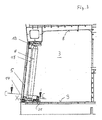
- in vergrößerter Schnittdarstellung quer zur Längsachse des Bootes die Nische mit Öffnung und einen Teil der Verschlussvorrichtung,
- Fig. 4
- in vergrößerter Darstellung die Einzelheit X in
Fig. 3 und - Fig. 5
- einen Schnitt längs der Schnittlinie C-C in
Fig. 3 .
- Fig. 1
- in a highly simplified schematic side view of a boat with an opening in the outer skin and a device for closing the same,
- Fig. 2
- in an enlarged view the opening of the boat according to
Fig. 1 with the device for closing, seen from the inside, - Fig. 3
- in an enlarged sectional view transversely to the longitudinal axis of the boat, the niche with opening and a part of the closure device,
- Fig. 4
- in an enlarged view the detail X in
Fig. 3 and - Fig. 5
- a section along the section line CC in
Fig. 3 ,
Das in
Die auf der Trommel 6 aufgewickelte Stoffbahn 5 ist zunächst über eine parallel zur Trommel 6 nahe der Öffnung 4 angeordnete Umlenkrolle 10 geführt und erstreckt sich von dort über die Öffnung 4 bis zum anderen Ende der Öffnung. Dort sind gegenüber der Öffnung 4 in der Nische 3 nach innen versetzt zwei hydraulisch angetriebene Seilwinden 11 und 12 angeordnet, deren Seile zunächst nahe der Decke 8 bzw. dem Boden 9 umgelenkt und dort in Schienen 13 und 14 geführt sind, die eine Führung für die Stoffbahn 5 nahe der Decke 8 und dem Boden 9 in Längsrichtung 7 der Öffnung 4 bilden. Die freien Enden der Seile der Seilwinden 11 und 12 greifen nahe den Ecken am freien Ende der Stoffbahn 5 an.The wound on the
Die Seilwinden 11 und 12 weisen Hydraulikmotoren auf und dienen Primär zum Abwickeln der Stoffbahn 5 von der Trommel 6 zum Verschlie-βen der Öffnung 4. In umgekehrter Richtung, also zum Aufwickeln der Stoffbahn 5 und zum Freistellen der Öffnung 4 weist die Trommel 6 einen hydraulischen Antrieb auf, der in
Die Schienen 13 und 14 erstrecken sich nahe den oberen und unteren Rändern der Öffnung 4 und führen die Stoffbahn 5 in Längsrichtung. Hierzu sind an den Längsrändern der Stoffbahn, wie aus
Die obere Schiene 13 ist an der Decke 8 fest angebracht, die untere Schiene 14 hingegen, die sich ebenfalls über nahezu die gesamte Länge der Öffnung 4 erstreckt, ist an einer Spannvorrichtung in Form eines hydraulischen Spannelementes 16 angebracht. Dieses hydraulische Spannelement 16 erstreckt sich über die gesamte Länge der Schiene 14 und besteht aus einem quaderförmigen im Querschnitt nahezu quadratischen Gehäuse 17, das an seiner Oberseite mit einem sich über etwa die gesamte Länge des Gehäuses erstreckenden Schlitz 18 versehen ist, durch den ein Steg 19 eines darin beweglich gelagerten T-Trägers 20 geführt ist. Das freie Ende des Stegs 19 ist fest mit der unteren Schiene 14 verbunden.The
Darüber hinaus ist eine Dichtmanschette 21 vorgesehen, welche einerseits am Gehäuse 17 und andererseits an der Schiene 14 anschließt und den dazwischen liegenden Raum abdichtet. Benachbart zu dem Steg 19 des T-Trägers 20 liegt in dem durch die oberen und seitlichen Seiten des Gehäuses 17 einerseits und durch den T-Träger 20 andererseits begrenzten Raum jeweils ein lang gestrecktes elastisches schlauchförmiges Gefäß 22, welches hydraulisch beaufschlagbar ist. Wenn die beiden hydraulisch miteinander verbundenen Gefäße 22 mit Hydraulikflüssigkeit druckbeaufschlagt werden, dehnen sich diese aus. Dies ist allerdings wegen der starren Wände des Gehäuses 17 des ebenfalls starren T-Trägers 20 nur in eine Richtung 23 quer zur Längsrichtung 7 möglich, wodurch der T-Träger 20 innerhalb des Gehäuses 17 nach unten gedrückt wird. Mit diesem wandert auch die Schiene 14 nach unten, wodurch die zwischen der oberen Schiene 13 und der unteren Schiene 14 in Schließstellung befindliche Stoffbahn 5 in Richtung 23 gespannt wird.In addition, a sealing collar 21 is provided which connects on the one hand to the
Da die Gefäße 22 sich über die gesamte Länge des Gehäuses 17 und somit auch der Schiene 14 erstrecken, werden durch die Hydraulik selbsttätig Toleranzen, welche durch die Form der Stoffbahn oder die Anordnung der Schienen 13, 14 bedingt sind, ausgeglichen. Ebenso ist sichergestellt, dass die Zugkräfte ausschließlich in Querrichtung zur Richtung 7 in der Stoffbahn 5 verlaufen.Since the
Während die Seilwinden 11 und 12 zum Verschließen der Öffnung in Aufwickelrichtung aktiviert werden, ist die Trommel 6 über einen in
Die Seilwinden 11 und 12 sowie der hydraulische Antrieb 24, 25 der Trommel 6 können nicht nur zum Öffnen und Verschließen der Öffnung 4, d. h. zum Auf- bzw. Abwickeln der Stoffbahn 5 angesteuert werden, sondern auch gegensinnig , sodass eine Zugkraft in Längsrichtung 7 der Stoffbahn 5 aufgebracht wird, wodurch sichergestellt ist, dass die Stoffbahn 5 in abgewickelter, also in Schließstellung, nahezu in einer Ebene verläuft. Sie ist dabei so angeordnet, dass ihre Außenseite etwa in Flucht mit der Bootswandung 2 verläuft.The
- 11
- - Boot- boat
- 22
- - Bootswandung- Boat wall
- 33
- - Nische- niche
- 44
- - Öffnung- opening
- 55
- - Stoffbahn- Fabric
- 66
- - Trommel- drum
- 77
- - Längsrichtung- longitudinal direction
- 88th
- - Decke- Blanket
- 99
- - Boden- Ground
- 1010
- - Umlenkrolle- pulley
- 1111
- - Seilwinde- winch
- 1212
- - Seilwinde- winch
- 1313
- - Schiene oben- rail above
- 1414
- - Schiene unten- Rail below
- 1515
- - Kulissensteine- Sliding stones
- 1616
- - hydraulisches Spannelement- Hydraulic tensioning element
- 1717
- - Gehäuse von 16- Housing of 16
- 1818
- - Schlitz von 17- slot of 17
- 1919
- - Steg- Footbridge
- 2020
- - T-Träger- T-beam
- 2121
- - Dichtmanschette- sealing collar
- 2222
- - Gefäße- Vessels
- 2323
- - Spannrichtung/Entspannrichtung- Clamping direction / relaxation direction
- 2424
- - Kettenrad- Sprocket
- 2525
- - Hydraulikmotor- Hydraulic motor
Claims (15)
- A device for closing a lateral opening (4) in the outer hull or wall (2) of a marine vessel (1), in particular for closing an opening (4) which is formed by a marine vessel recess (3), with a material (5) which can extend over almost the whole opening (4) and which for the release of the opening (4) can be removed from this opening, with a guide (13, 14) which extends along two oppositely lying sides of the opening (4) and receives and holds the material (5) at two sides, with at least one tensioning device (16), with which the material (5) can be tensioned in a direction (23) transverse to the guide, wherein the guide comprises two oppositely lying rails (13, 14), between which the material (5) is held and guided, characterised in that the one rail (13) at least in the tensioning direction (23) is arranged fixed to the marine vessel, and the other rail (14) at least in the tensioning direction (23) is arranged in a movable manner, and that the at least one tensioning element (16) is provided between the movable rail (14) on a part which is fixed to the marine vessel.
- A device according to claim 1, characterised in that the rails (13, 14) extend in the longitudinal direction (7) of the opening.
- A device according to claim 1 or 2, characterised in that the tensioning element (16) is constructed according to the functioning principle of a hydraulic cylinder and extends over the length of the rail (14) connected thereto.
- A device according to claim 3, characterised in that the pressure space of the tensioning element is formed by way of at least one elastic, flexible tubing-like vessel (22) which is supported by walls (17, 20) of the tensioning element (16) which are rigid compared to said vessel and which are movable to one another.
- A device according to claim 4, characterised in that the tensioning element (16) comprises a parallelepiped housing (17) with a slot (18) in one housing side, said slot extending over the length of the housing (17) and through which the web (19) of a T-beam (20) mounted within the housing (17) is guided, wherein two elastic flexible tubing-like vessels (22) are arranged within the housing (17), which in each case bear on one side of the web (19) and form the pressure space of the tensioning element (16).
- A device according to claim 5, characterised in that the housing (17) of the tensioning element (16) is attached in a manner fixed to the marine vessel, and a rail (14) of the guide is fastened on the end of the web (19) which is remote from the housing.
- A device according to one of the preceding claims, characterised in that the material (5) can be rolled onto a drum (6) which is preferably arranged close to a narrow side of the opening (4).
- A device according to claim 7, characterised in that the drum (6) is mounted in a manner fixed to the marine vessel and is preferably driven hydraulically at least in the winding-up direction.
- A device according to claim 7 or 8, characterised in that preferably hydraulically driven cable winches for winding the material from the drum (6) are provided on the side of the opening (4) which lies opposite the drum (6), wherein the cables run along the rails (13, 14), preferably within the rails (13, 14) and engage at the free end of the material (5).
- A device according to one of the preceding claims, characterised in that the hydraulic drives (25), for winding the material (5) onto and from the drum (6) can be locked or can be impinged in opposite directions to one another with a presettable force.
- A device according to one of the preceding claims, characterised in that the material (5) is constructed in a multilayered manner.
- A device according to claim 11, characterised in that the material (5) comprises a reflection layer, preferably in the form of a metal foil.
- A device according to claim 11 or 12, characterised in that the material (5) comprises a load-carrying main layer which is preferably formed from a multilayered sailing cloth.
- A device according to one of the preceding claims, characterised in that the material (5) is reinforced with high tensile-strength fibre.
- A device according to one of the preceding claims, characterised in that the material (5) at least on its edges on the rail side is designed in a reinforced manner and is provided with sliding blocks (15) which are guided on or in the rails (13, 14) with a positive fit.
Priority Applications (1)
| Application Number | Priority Date | Filing Date | Title |
|---|---|---|---|
| PL11181070T PL2433859T3 (en) | 2010-09-25 | 2011-09-13 | Device for closing a side opening in the shell or wall of a boat |
Applications Claiming Priority (1)
| Application Number | Priority Date | Filing Date | Title |
|---|---|---|---|
| DE102010046608A DE102010046608B4 (en) | 2010-09-25 | 2010-09-25 | Device for closing a lateral opening in the outer skin or wall of a boat |
Publications (2)
| Publication Number | Publication Date |
|---|---|
| EP2433859A1 EP2433859A1 (en) | 2012-03-28 |
| EP2433859B1 true EP2433859B1 (en) | 2014-07-23 |
Family
ID=44677707
Family Applications (1)
| Application Number | Title | Priority Date | Filing Date |
|---|---|---|---|
| EP11181070.1A Active EP2433859B1 (en) | 2010-09-25 | 2011-09-13 | Device for closing a side opening in the shell or wall of a boat |
Country Status (6)
| Country | Link |
|---|---|
| EP (1) | EP2433859B1 (en) |
| KR (1) | KR101388479B1 (en) |
| DE (1) | DE102010046608B4 (en) |
| DK (1) | DK2433859T3 (en) |
| ES (1) | ES2508516T3 (en) |
| PL (1) | PL2433859T3 (en) |
Families Citing this family (6)
| Publication number | Priority date | Publication date | Assignee | Title |
|---|---|---|---|---|
| NL2011785C2 (en) * | 2013-11-12 | 2015-05-13 | Linssen Holding B V | VESSEL AND FLEXIBLE PANEL SUITABLE FOR SUCH VESSEL. |
| CN105129026B (en) * | 2015-08-28 | 2017-06-30 | 常石集团(舟山)造船有限公司 | A kind of bulk goods Cover of cabin |
| FR3053309B1 (en) * | 2016-06-29 | 2019-07-19 | Dcns | NAVAL PLATFORM COMPRISING A SUPERSTRUCTURE COMPRISING AN OPENING ACCESS TO A NICHE |
| DE102016221146A1 (en) * | 2016-10-27 | 2018-05-03 | Thyssenkrupp Ag | shutter blade |
| KR102219935B1 (en) * | 2020-02-12 | 2021-02-25 | 주식회사 희성산업 | Screen with shield and screen door using the same |
| KR102684550B1 (en) * | 2022-01-14 | 2024-07-15 | 국방과학연구소 | Fiber optic cable guidance system for guidance of underwater vehicle and fiber optic cable guidance apparatus thererof |
Citations (1)
| Publication number | Priority date | Publication date | Assignee | Title |
|---|---|---|---|---|
| US20060240765A1 (en) * | 2005-04-20 | 2006-10-26 | Cheng Shao C | Closure device having ventilating structure |
Family Cites Families (9)
| Publication number | Priority date | Publication date | Assignee | Title |
|---|---|---|---|---|
| GB167583A (en) * | 1920-05-11 | 1921-08-11 | Charles Edmund Peczenik | Improvements in or relating to vehicle-bodies and roofs |
| FI77823C (en) * | 1987-05-04 | 1989-05-10 | Macgregor Navire Sa | Cover arrangement for a dry cargo ship. |
| US5562064A (en) * | 1995-03-08 | 1996-10-08 | Diversified Technologies, Inc. | Apparatus and method for assessing damage and patching openings in hulls of marine vessels |
| SE523348C2 (en) * | 2002-08-15 | 2004-04-13 | Totalfoersvarets Forskningsins | Transparent box with radar reflective properties |
| DE10256984B4 (en) * | 2002-12-05 | 2005-08-11 | Buck Neue Technologien Gmbh | Radar-disguised launcher |
| US7451717B1 (en) * | 2004-05-21 | 2008-11-18 | Conocophillips Company | Systems and processes for covering openings of marine vessel hulls |
| US7143717B2 (en) * | 2004-10-27 | 2006-12-05 | Murphy Mark J | Cover attachment system |
| DE102005004682A1 (en) * | 2005-02-02 | 2006-08-17 | Blohm + Voss Gmbh | Ship with camouflage device |
| GB2431426A (en) * | 2005-10-18 | 2007-04-25 | Oceanair Marine Ltd | Roller blind |
-
2010
- 2010-09-25 DE DE102010046608A patent/DE102010046608B4/en not_active Expired - Fee Related
-
2011
- 2011-09-13 DK DK11181070.1T patent/DK2433859T3/en active
- 2011-09-13 ES ES11181070.1T patent/ES2508516T3/en active Active
- 2011-09-13 EP EP11181070.1A patent/EP2433859B1/en active Active
- 2011-09-13 PL PL11181070T patent/PL2433859T3/en unknown
- 2011-09-16 KR KR1020110093625A patent/KR101388479B1/en not_active Expired - Fee Related
Patent Citations (1)
| Publication number | Priority date | Publication date | Assignee | Title |
|---|---|---|---|---|
| US20060240765A1 (en) * | 2005-04-20 | 2006-10-26 | Cheng Shao C | Closure device having ventilating structure |
Also Published As
| Publication number | Publication date |
|---|---|
| DE102010046608A1 (en) | 2012-03-29 |
| KR101388479B1 (en) | 2014-04-23 |
| PL2433859T3 (en) | 2015-02-27 |
| EP2433859A1 (en) | 2012-03-28 |
| ES2508516T3 (en) | 2014-10-16 |
| DE102010046608B4 (en) | 2012-07-26 |
| DK2433859T3 (en) | 2014-10-06 |
| KR20120031883A (en) | 2012-04-04 |
Similar Documents
| Publication | Publication Date | Title |
|---|---|---|
| DE102010046608B4 (en) | Device for closing a lateral opening in the outer skin or wall of a boat | |
| DE10129022B4 (en) | Telescopic crane with superlift device | |
| DE102017130955A1 (en) | INFLATABLE SURFBOARD WITH DRIVE UNIT | |
| EP2292508B1 (en) | Hatch cover for closing off a hatch | |
| DE202017107820U1 (en) | Inflatable surfboard with drive unit | |
| DE102013210406A1 (en) | Convertible roof element, convertible roof construction and method of operation of the roof element | |
| EP0189154B1 (en) | Boat with retractable keel | |
| DD251112A5 (en) | SAIL BOAT | |
| EP1507311A1 (en) | Deploying device for a towed antenna or a towed cable | |
| EP2708394B1 (en) | Commercial vehicle with a slidable side curtain | |
| DE202013102410U1 (en) | Convertible roof element, convertible roof construction | |
| DE102010003662A1 (en) | ship | |
| DE102009014073B3 (en) | deckcrane | |
| EP1783047B1 (en) | Submarine with a tow-line | |
| DE10226618B4 (en) | Barrier or locking device | |
| EP3330170A1 (en) | System for roll stabilisation of boats and boat | |
| DE202016100483U1 (en) | Vehicle light crane with telescopic folding tip | |
| EP1099623B1 (en) | Inflatable swash bulkhead for decreasing free surfaces | |
| DE1155994B (en) | Device for stabilizing ships using steered, retractable fins | |
| DE8509163U1 (en) | Rig for vehicles with sails | |
| EP3725663A1 (en) | Hatch cover and method for configuring a hatch cover | |
| DD291054A5 (en) | WEATHER PROTECTION FOR COVERING LUKEN IV | |
| DE1252091C2 (en) | HYDROMECHANICAL LOCKING AND LOCKING DEVICE FOR FOLDING BARRELS | |
| DE1920655U (en) | ROLLABLE HATCH COVER DEVICE FOR INLAND SHIPS, GOODS CARS, LARGE-SCALE TRANSPORT CONTAINERS AND THE LIKE. | |
| DE102010048629A1 (en) | submarine |
Legal Events
| Date | Code | Title | Description |
|---|---|---|---|
| PUAI | Public reference made under article 153(3) epc to a published international application that has entered the european phase |
Free format text: ORIGINAL CODE: 0009012 |
|
| AK | Designated contracting states |
Kind code of ref document: A1 Designated state(s): AL AT BE BG CH CY CZ DE DK EE ES FI FR GB GR HR HU IE IS IT LI LT LU LV MC MK MT NL NO PL PT RO RS SE SI SK SM TR |
|
| AX | Request for extension of the european patent |
Extension state: BA ME |
|
| 17P | Request for examination filed |
Effective date: 20120912 |
|
| RAP1 | Party data changed (applicant data changed or rights of an application transferred) |
Owner name: THYSSENKRUPP MARINE SYSTEMS GMBH |
|
| 17Q | First examination report despatched |
Effective date: 20130417 |
|
| GRAP | Despatch of communication of intention to grant a patent |
Free format text: ORIGINAL CODE: EPIDOSNIGR1 |
|
| INTG | Intention to grant announced |
Effective date: 20140221 |
|
| GRAS | Grant fee paid |
Free format text: ORIGINAL CODE: EPIDOSNIGR3 |
|
| GRAP | Despatch of communication of intention to grant a patent |
Free format text: ORIGINAL CODE: EPIDOSNIGR1 |
|
| GRAA | (expected) grant |
Free format text: ORIGINAL CODE: 0009210 |
|
| INTG | Intention to grant announced |
Effective date: 20140606 |
|
| AK | Designated contracting states |
Kind code of ref document: B1 Designated state(s): AL AT BE BG CH CY CZ DE DK EE ES FI FR GB GR HR HU IE IS IT LI LT LU LV MC MK MT NL NO PL PT RO RS SE SI SK SM TR |
|
| REG | Reference to a national code |
Ref country code: GB Ref legal event code: FG4D Free format text: NOT ENGLISH |
|
| REG | Reference to a national code |
Ref country code: CH Ref legal event code: EP |
|
| REG | Reference to a national code |
Ref country code: IE Ref legal event code: FG4D Free format text: LANGUAGE OF EP DOCUMENT: GERMAN |
|
| REG | Reference to a national code |
Ref country code: AT Ref legal event code: REF Ref document number: 678693 Country of ref document: AT Kind code of ref document: T Effective date: 20140815 |
|
| REG | Reference to a national code |
Ref country code: DE Ref legal event code: R096 Ref document number: 502011003819 Country of ref document: DE Effective date: 20140904 |
|
| REG | Reference to a national code |
Ref country code: DK Ref legal event code: T3 Effective date: 20141002 |
|
| REG | Reference to a national code |
Ref country code: ES Ref legal event code: FG2A Ref document number: 2508516 Country of ref document: ES Kind code of ref document: T3 Effective date: 20141016 |
|
| REG | Reference to a national code |
Ref country code: SE Ref legal event code: TRGR |
|
| REG | Reference to a national code |
Ref country code: NL Ref legal event code: T3 |
|
| REG | Reference to a national code |
Ref country code: LT Ref legal event code: MG4D |
|
| PG25 | Lapsed in a contracting state [announced via postgrant information from national office to epo] |
Ref country code: BG Free format text: LAPSE BECAUSE OF FAILURE TO SUBMIT A TRANSLATION OF THE DESCRIPTION OR TO PAY THE FEE WITHIN THE PRESCRIBED TIME-LIMIT Effective date: 20141023 Ref country code: GR Free format text: LAPSE BECAUSE OF FAILURE TO SUBMIT A TRANSLATION OF THE DESCRIPTION OR TO PAY THE FEE WITHIN THE PRESCRIBED TIME-LIMIT Effective date: 20141024 Ref country code: LT Free format text: LAPSE BECAUSE OF FAILURE TO SUBMIT A TRANSLATION OF THE DESCRIPTION OR TO PAY THE FEE WITHIN THE PRESCRIBED TIME-LIMIT Effective date: 20140723 Ref country code: PT Free format text: LAPSE BECAUSE OF FAILURE TO SUBMIT A TRANSLATION OF THE DESCRIPTION OR TO PAY THE FEE WITHIN THE PRESCRIBED TIME-LIMIT Effective date: 20141124 Ref country code: NO Free format text: LAPSE BECAUSE OF FAILURE TO SUBMIT A TRANSLATION OF THE DESCRIPTION OR TO PAY THE FEE WITHIN THE PRESCRIBED TIME-LIMIT Effective date: 20141023 |
|
| REG | Reference to a national code |
Ref country code: DE Ref legal event code: R084 Ref document number: 502011003819 Country of ref document: DE |
|
| PG25 | Lapsed in a contracting state [announced via postgrant information from national office to epo] |
Ref country code: CY Free format text: LAPSE BECAUSE OF FAILURE TO SUBMIT A TRANSLATION OF THE DESCRIPTION OR TO PAY THE FEE WITHIN THE PRESCRIBED TIME-LIMIT Effective date: 20140723 Ref country code: LV Free format text: LAPSE BECAUSE OF FAILURE TO SUBMIT A TRANSLATION OF THE DESCRIPTION OR TO PAY THE FEE WITHIN THE PRESCRIBED TIME-LIMIT Effective date: 20140723 Ref country code: RS Free format text: LAPSE BECAUSE OF FAILURE TO SUBMIT A TRANSLATION OF THE DESCRIPTION OR TO PAY THE FEE WITHIN THE PRESCRIBED TIME-LIMIT Effective date: 20140723 Ref country code: HR Free format text: LAPSE BECAUSE OF FAILURE TO SUBMIT A TRANSLATION OF THE DESCRIPTION OR TO PAY THE FEE WITHIN THE PRESCRIBED TIME-LIMIT Effective date: 20140723 Ref country code: IS Free format text: LAPSE BECAUSE OF FAILURE TO SUBMIT A TRANSLATION OF THE DESCRIPTION OR TO PAY THE FEE WITHIN THE PRESCRIBED TIME-LIMIT Effective date: 20141123 |
|
| REG | Reference to a national code |
Ref country code: PL Ref legal event code: T3 |
|
| REG | Reference to a national code |
Ref country code: DE Ref legal event code: R084 Ref document number: 502011003819 Country of ref document: DE Effective date: 20150206 |
|
| REG | Reference to a national code |
Ref country code: DE Ref legal event code: R097 Ref document number: 502011003819 Country of ref document: DE |
|
| PG25 | Lapsed in a contracting state [announced via postgrant information from national office to epo] |
Ref country code: EE Free format text: LAPSE BECAUSE OF FAILURE TO SUBMIT A TRANSLATION OF THE DESCRIPTION OR TO PAY THE FEE WITHIN THE PRESCRIBED TIME-LIMIT Effective date: 20140723 Ref country code: CZ Free format text: LAPSE BECAUSE OF FAILURE TO SUBMIT A TRANSLATION OF THE DESCRIPTION OR TO PAY THE FEE WITHIN THE PRESCRIBED TIME-LIMIT Effective date: 20140723 Ref country code: RO Free format text: LAPSE BECAUSE OF FAILURE TO SUBMIT A TRANSLATION OF THE DESCRIPTION OR TO PAY THE FEE WITHIN THE PRESCRIBED TIME-LIMIT Effective date: 20140723 Ref country code: MC Free format text: LAPSE BECAUSE OF FAILURE TO SUBMIT A TRANSLATION OF THE DESCRIPTION OR TO PAY THE FEE WITHIN THE PRESCRIBED TIME-LIMIT Effective date: 20140723 Ref country code: SK Free format text: LAPSE BECAUSE OF FAILURE TO SUBMIT A TRANSLATION OF THE DESCRIPTION OR TO PAY THE FEE WITHIN THE PRESCRIBED TIME-LIMIT Effective date: 20140723 Ref country code: LU Free format text: LAPSE BECAUSE OF FAILURE TO SUBMIT A TRANSLATION OF THE DESCRIPTION OR TO PAY THE FEE WITHIN THE PRESCRIBED TIME-LIMIT Effective date: 20140913 |
|
| REG | Reference to a national code |
Ref country code: CH Ref legal event code: PL |
|
| PLBE | No opposition filed within time limit |
Free format text: ORIGINAL CODE: 0009261 |
|
| STAA | Information on the status of an ep patent application or granted ep patent |
Free format text: STATUS: NO OPPOSITION FILED WITHIN TIME LIMIT |
|
| REG | Reference to a national code |
Ref country code: IE Ref legal event code: MM4A |
|
| PG25 | Lapsed in a contracting state [announced via postgrant information from national office to epo] |
Ref country code: BE Free format text: LAPSE BECAUSE OF NON-PAYMENT OF DUE FEES Effective date: 20140930 |
|
| 26N | No opposition filed |
Effective date: 20150424 |
|
| PG25 | Lapsed in a contracting state [announced via postgrant information from national office to epo] |
Ref country code: CH Free format text: LAPSE BECAUSE OF NON-PAYMENT OF DUE FEES Effective date: 20140930 Ref country code: LI Free format text: LAPSE BECAUSE OF NON-PAYMENT OF DUE FEES Effective date: 20140930 |
|
| PG25 | Lapsed in a contracting state [announced via postgrant information from national office to epo] |
Ref country code: IE Free format text: LAPSE BECAUSE OF NON-PAYMENT OF DUE FEES Effective date: 20140913 |
|
| PG25 | Lapsed in a contracting state [announced via postgrant information from national office to epo] |
Ref country code: SI Free format text: LAPSE BECAUSE OF FAILURE TO SUBMIT A TRANSLATION OF THE DESCRIPTION OR TO PAY THE FEE WITHIN THE PRESCRIBED TIME-LIMIT Effective date: 20140723 |
|
| PG25 | Lapsed in a contracting state [announced via postgrant information from national office to epo] |
Ref country code: SM Free format text: LAPSE BECAUSE OF FAILURE TO SUBMIT A TRANSLATION OF THE DESCRIPTION OR TO PAY THE FEE WITHIN THE PRESCRIBED TIME-LIMIT Effective date: 20140723 |
|
| PG25 | Lapsed in a contracting state [announced via postgrant information from national office to epo] |
Ref country code: MT Free format text: LAPSE BECAUSE OF FAILURE TO SUBMIT A TRANSLATION OF THE DESCRIPTION OR TO PAY THE FEE WITHIN THE PRESCRIBED TIME-LIMIT Effective date: 20140723 |
|
| PG25 | Lapsed in a contracting state [announced via postgrant information from national office to epo] |
Ref country code: HU Free format text: LAPSE BECAUSE OF FAILURE TO SUBMIT A TRANSLATION OF THE DESCRIPTION OR TO PAY THE FEE WITHIN THE PRESCRIBED TIME-LIMIT; INVALID AB INITIO Effective date: 20110913 |
|
| REG | Reference to a national code |
Ref country code: FR Ref legal event code: PLFP Year of fee payment: 6 |
|
| REG | Reference to a national code |
Ref country code: FR Ref legal event code: PLFP Year of fee payment: 7 |
|
| REG | Reference to a national code |
Ref country code: AT Ref legal event code: MM01 Ref document number: 678693 Country of ref document: AT Kind code of ref document: T Effective date: 20160913 |
|
| PG25 | Lapsed in a contracting state [announced via postgrant information from national office to epo] |
Ref country code: AT Free format text: LAPSE BECAUSE OF NON-PAYMENT OF DUE FEES Effective date: 20160913 |
|
| PG25 | Lapsed in a contracting state [announced via postgrant information from national office to epo] |
Ref country code: MK Free format text: LAPSE BECAUSE OF FAILURE TO SUBMIT A TRANSLATION OF THE DESCRIPTION OR TO PAY THE FEE WITHIN THE PRESCRIBED TIME-LIMIT Effective date: 20140723 |
|
| REG | Reference to a national code |
Ref country code: FR Ref legal event code: PLFP Year of fee payment: 8 |
|
| PG25 | Lapsed in a contracting state [announced via postgrant information from national office to epo] |
Ref country code: AL Free format text: LAPSE BECAUSE OF FAILURE TO SUBMIT A TRANSLATION OF THE DESCRIPTION OR TO PAY THE FEE WITHIN THE PRESCRIBED TIME-LIMIT Effective date: 20140723 |
|
| REG | Reference to a national code |
Ref country code: DE Ref legal event code: R081 Ref document number: 502011003819 Country of ref document: DE Owner name: THYSSENKRUPP MARINE SYSTEMS GMBH, DE Free format text: FORMER OWNER: THYSSENKRUPP MARINE SYSTEMS GMBH, 24143 KIEL, DE |
|
| PGFP | Annual fee paid to national office [announced via postgrant information from national office to epo] |
Ref country code: ES Payment date: 20221122 Year of fee payment: 12 |
|
| PGFP | Annual fee paid to national office [announced via postgrant information from national office to epo] |
Ref country code: TR Payment date: 20230912 Year of fee payment: 13 Ref country code: NL Payment date: 20230920 Year of fee payment: 13 Ref country code: GB Payment date: 20230920 Year of fee payment: 13 Ref country code: FI Payment date: 20230920 Year of fee payment: 13 |
|
| PGFP | Annual fee paid to national office [announced via postgrant information from national office to epo] |
Ref country code: SE Payment date: 20230920 Year of fee payment: 13 Ref country code: PL Payment date: 20230906 Year of fee payment: 13 Ref country code: FR Payment date: 20230928 Year of fee payment: 13 Ref country code: DK Payment date: 20230925 Year of fee payment: 13 Ref country code: DE Payment date: 20230920 Year of fee payment: 13 |
|
| PGFP | Annual fee paid to national office [announced via postgrant information from national office to epo] |
Ref country code: IT Payment date: 20230927 Year of fee payment: 13 |
|
| REG | Reference to a national code |
Ref country code: ES Ref legal event code: FD2A Effective date: 20241029 |
|
| PG25 | Lapsed in a contracting state [announced via postgrant information from national office to epo] |
Ref country code: ES Free format text: LAPSE BECAUSE OF NON-PAYMENT OF DUE FEES Effective date: 20230914 |
|
| PG25 | Lapsed in a contracting state [announced via postgrant information from national office to epo] |
Ref country code: ES Free format text: LAPSE BECAUSE OF NON-PAYMENT OF DUE FEES Effective date: 20230914 |
|
| REG | Reference to a national code |
Ref country code: DE Ref legal event code: R119 Ref document number: 502011003819 Country of ref document: DE |
|
| PG25 | Lapsed in a contracting state [announced via postgrant information from national office to epo] |
Ref country code: FI Free format text: LAPSE BECAUSE OF NON-PAYMENT OF DUE FEES Effective date: 20240913 |
|
| REG | Reference to a national code |
Ref country code: DK Ref legal event code: EBP Effective date: 20240930 |
|
| REG | Reference to a national code |
Ref country code: SE Ref legal event code: EUG |
|
| REG | Reference to a national code |
Ref country code: NL Ref legal event code: MM Effective date: 20241001 |
|
| GBPC | Gb: european patent ceased through non-payment of renewal fee |
Effective date: 20240913 |
|
| PG25 | Lapsed in a contracting state [announced via postgrant information from national office to epo] |
Ref country code: NL Free format text: LAPSE BECAUSE OF NON-PAYMENT OF DUE FEES Effective date: 20241001 |
|
| PG25 | Lapsed in a contracting state [announced via postgrant information from national office to epo] |
Ref country code: DE Free format text: LAPSE BECAUSE OF NON-PAYMENT OF DUE FEES Effective date: 20250401 |
|
| PG25 | Lapsed in a contracting state [announced via postgrant information from national office to epo] |
Ref country code: GB Free format text: LAPSE BECAUSE OF NON-PAYMENT OF DUE FEES Effective date: 20240913 |
|
| PG25 | Lapsed in a contracting state [announced via postgrant information from national office to epo] |
Ref country code: IT Free format text: LAPSE BECAUSE OF NON-PAYMENT OF DUE FEES Effective date: 20240913 |
|
| PG25 | Lapsed in a contracting state [announced via postgrant information from national office to epo] |
Ref country code: FR Free format text: LAPSE BECAUSE OF NON-PAYMENT OF DUE FEES Effective date: 20240930 |
|
| PG25 | Lapsed in a contracting state [announced via postgrant information from national office to epo] |
Ref country code: DK Free format text: LAPSE BECAUSE OF NON-PAYMENT OF DUE FEES Effective date: 20240930 |
|
| PG25 | Lapsed in a contracting state [announced via postgrant information from national office to epo] |
Ref country code: SE Free format text: LAPSE BECAUSE OF NON-PAYMENT OF DUE FEES Effective date: 20240914 |
|
| PG25 | Lapsed in a contracting state [announced via postgrant information from national office to epo] |
Ref country code: PL Free format text: LAPSE BECAUSE OF NON-PAYMENT OF DUE FEES Effective date: 20240913 |