EP2428391A2 - Fahrdrahtklemme für Oberleitungskreuzungen - Google Patents
Fahrdrahtklemme für Oberleitungskreuzungen Download PDFInfo
- Publication number
- EP2428391A2 EP2428391A2 EP11450117A EP11450117A EP2428391A2 EP 2428391 A2 EP2428391 A2 EP 2428391A2 EP 11450117 A EP11450117 A EP 11450117A EP 11450117 A EP11450117 A EP 11450117A EP 2428391 A2 EP2428391 A2 EP 2428391A2
- Authority
- EP
- European Patent Office
- Prior art keywords
- contact wire
- clamp
- wire clamp
- overhead
- contact
- Prior art date
- Legal status (The legal status is an assumption and is not a legal conclusion. Google has not performed a legal analysis and makes no representation as to the accuracy of the status listed.)
- Granted
Links
Images

Classifications
-
- B—PERFORMING OPERATIONS; TRANSPORTING
- B60—VEHICLES IN GENERAL
- B60M—POWER SUPPLY LINES, AND DEVICES ALONG RAILS, FOR ELECTRICALLY- PROPELLED VEHICLES
- B60M1/00—Power supply lines for contact with collector on vehicle
- B60M1/12—Trolley lines; Accessories therefor
- B60M1/20—Arrangements for supporting or suspending trolley wires, e.g. from buildings
- B60M1/24—Clamps; Splicers; Anchor tips
Definitions
- the invention relates to a trolley clamp for overhead intersections for electrically operated rail vehicles whose clamping jaws actuated by a screw clamp the contact wire of the main tracks.
- crossing bars are used in such cases almost exclusively, which are clamped in the form of a frame on the lower contact wire.
- These up to 2500mm long devices prevent vertical separation of the contact wires and at the same time allow longitudinal movement of the same.
- these crossing bars bring problems in terms of space requirements, weight, the strength of the rod, the cost, installation effort, etc.
- the invention has set itself the goal of creating a contact wire clamp for overhead intersections for electrically operated rail vehicles, which avoids the disadvantages of the crossing bars.
- the inventive solution eliminates the crossing rod and there are arbitrarily small crossing angles easily possible.
- the contact wires opposite end of the terminal for receiving a Kausche a hanger rope is formed.
- the contact wire intersection thus acts as a trailer, whereby the usual and necessary distance to the next trailer can be met and thereby increases the horizontal distance between the contact wires to a sufficient extent to prevent damage by collision with hanging clamps.
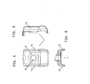
- a contact wire clamp according to the invention consists of two symmetrical clamp halves 1 and jaws in the middle by a Screw 2 are connected together.
- the clamp clamps the trolley 3 of the main tracks and is provided with a through hole (bulge) 4 for the trolley 5 of the crossing tracks.
- the intersecting contact wire 5 rests on the contact wire 3 of the main tracks and is displaced as far as possible without friction. In height it is limited by the screw 2 of the clamp halves 1 in the stroke and laterally, positioned by the clamp halves 1, in the intersection.
- the clamp takes on the upper side of a hanger rope 6 by means of a Kausche 7.
- the screw hole 8 is an inwardly coined conical shape 9 for the purpose of securing the screw, since the nut 10 of the stainless steel screw wedged into the relatively softer copper of the terminal.
- the through holes 8 for the screw 2 in both jaws 1 are larger than the outer diameter 11 of the screw, whereby the distance 12 of the two jaws is adjustable.
- edges 13 of the two jaws 1 are bent wing-shaped outward. This avoids that the contact wire 5 of the crossing tracks may be damaged by a sharp edge.
Landscapes
- Engineering & Computer Science (AREA)
- Mechanical Engineering (AREA)
- Clamps And Clips (AREA)
- Suspension Of Electric Lines Or Cables (AREA)
Abstract
Description
- Die Erfindung bezieht sich auf eine Fahrdrahtklemme für Oberleitungskreuzungen für elektrisch betriebene Schienenfahrzeuge, deren durch eine Schraube betätigte Klemmbacken den Fahrdraht der Hauptgleise festklemmen.
- Im Fahrleitungsbereich treten Kreuzungen von Fahrdrähten besonders bei Weichen und sonstigen Schienenkreuzungen auf. In diesen Bereichen besteht die Gefahr, dass der Stromabnehmer den oberen Fahrdraht im Kreuzungsbereich anhebt, während der untere Fahrdraht in seiner Position verharrt. Ohne eine entsprechende Vorrichtung würde der Stromabnehmer sich in diesem Fall im unteren Fahrdraht verfangen und schwere Schäden an Fahrleitung und Triebfahrzeug verursachen. Daher wird in solchen Bereichen der Fahrleitung eine Vorrichtung benötigt, welche die beiden Fahrdrähte in der vertikalen Ebene zusammenhält, in der horizontalen Ebene jedoch eine Längsbewegung zulässt. Diese Längsbewegung wird durch die Ausdehnung der Fahrdrähte entsprechend der Außentemperatur und im Zusammenhang mit den mit den Fahrdrähten verbundenen automatischen Abspannvorrichtungen verursacht. Zusätzlich sollte diese Verbindung, wie alle anderen Komponenten, die im Kettenwerk einer Fahrleitung hängen, möglichst leicht sein, damit der Stromabnehmer keine durch Massenkonzentration verursachten »harten" Stellen am Fahrdraht vorfindet.
- Bisher werden in solchen Fällen fast ausschließlich sogenannte Kreuzungsstäbe verwendet, welche rahmenförmig am unteren Fahrdraht festgeklemmt werden. Diese bis zu 2500mm langen Vorrichtungen verhindern eine vertikale Trennung der Fahrdrähte und erlauben gleichzeitig eine Längsbewegung derselben. Diese Kreuzungsstäbe bringen jedoch Probleme beim Platzbedarf, Gewicht, der Festigkeit des Stabes, den Kosten, Montageaufwand etc.
- Die Erfindung hat es sich zum Ziel gesetzt, eine Fahrdrahtklemme für Oberleitungskreuzungen für elektrisch betriebene Schienenfahrzeuge zu schaffen, welche die aufgezeigten Nachteile der Kreuzungsstäbe vermeidet.
- Erreicht wird dies bei einer Fahrdrahtklemme der eingangs genannten Art dadurch, dass zwischen den beiden Klemmbacken eine Durchgangsöffnung für den auf dem Fahrdraht der Hauptgleise aufliegenden Fahrdraht der kreuzenden Gleise angeordnet ist.
- Durch die erfindungsgemäße Lösung entfällt der Kreuzungsstab und es sind beliebig kleine Kreuzungswinkel problemlos möglich.
- Im Rahmen der Erfindung ist es zweckmäßig, wenn die seitlichen Kanten der beiden Klemmbacken flügelförmig nach außen gebogen sind. Dadurch wird eine eventuelle Beschädigung der Fahrdrähte wirkungsvoll vermieden.
- Nach einem weiteren Merkmal der Erfindung ist das den Fahrdrähten gegenüberliegende Ende der Klemme zur Aufnahme einer Kausche eines Hängerseils ausgebildet.
- Die Fahrdrahtkreuzung fungiert dadurch auch als Hänger, wodurch der übliche und notwendige Abstand zum nächsten Hänger eingehalten werden kann und sich dadurch der horizontale Abstand zwischen den Fahrdrähten auf ein ausreichendes Maß vergrößert, um Beschädigungen durch Kollision mit Hängeklemmen zu verhindern.
- Nachstehend ist die Erfindung anhand eines in den Zeichnungen dargestellten Ausführungsbeispieles näher beschrieben ohne auf diese Beispiel beschränkt zu sein. Dabei zeigen:
- Fig. 1
- eine Seitenansicht einer erfindungsgemäß ausgebildeten Oberleitungskreuzung;
- Fig. 2
- die Draufsicht auf die Kreuzung nach
Fig. 1 ; - Fig. 3
- eine Seitenansicht der Kreuzung nach
Fig. 1 ; - Fig. 4
- in vergrößertem Maßstab die Ansicht einer erfindungsgemäßen Fahrdrahtklemme;
- Fig. 5
- eine Seitenansicht der Klemme nach
Fig. 4 und - Fig. 6
- eine Draufsicht auf die Klemme nach den
Fig. 4 und 5 . - Gemäß den Zeichnungen besteht eine erfindungsgemäße Fahrdrahtklemme aus zwei symmetrischen Klemmenhälften 1 bzw. Klemmbacken, die in der Mitte durch eine Schraube 2 miteinander verbunden sind. Die Klemme klemmt den Fahrdraht 3 der Hauptgleise und ist mit einer Durchgangsöffnung (Ausbauchung) 4 für den Fahrdraht 5 der kreuzenden Gleise versehen.
- Der kreuzende Fahrdraht 5 liegt auf dem Fahrdraht 3 der Hauptgleise auf und ist der Länge nach möglichst reibungsfrei verschiebbar. In der Höhe ist er durch die Schraube 2 der Klemmenhälften 1 im Anhub begrenzt und seitlich, durch die Klemmenhälften 1, im Kreuzungspunkt positioniert.
- Die Klemme nimmt an der oberen Seite ein Hängerseil 6 mit Hilfe einer Kausche 7 auf.
- Rund um das Schraubenloch 8 befindet sich eine nach innen geprägte Kegelform 9 zwecks Schraubensicherung, da sich die Mutter 10 der Niro-Schraube in das in Relation weichere Kupfer der Klemme verkeilt. Um eine Verwendung für verschiedene Durchmesser von Fahrdrähten zu ermöglichen, sind die Durchgangsöffnungen 8 für die Schraube 2 in beiden Klemmbacken 1 größer als der Außendurchmesser 11 der Schraube, wodurch der Abstand 12 der beiden Klemmbacken verstellbar ist.
- Die Kanten 13 der beiden Klemmbacken 1 sind flügelförmig nach außen gebogen. Dadurch wird vermieden, dass der Fahrdraht 5 der kreuzenden Gleise durch eine scharfe Kante eventuell beschädigt wird.
- Im Rahmen der Erfindung sind zahlreiche Abänderungen möglich, insbesondere kann die Form der Klemme anders als dargestellt gewählt werden, um die Öffnung für den Durchgang des Fahrdrahtes 5 der kreuzenden Gleise zu schaffen.
Claims (3)
- Fahrdrahtklemme für Oberleitungskreuzungen für elektrisch betriebene Schienenfahrzeuge, deren durch eine Schraube (2) betätigte Klemmbacken (1) den Fahrdraht (3) der Hauptgleise festklemmen, dadurch gekennzeichnet, dass zwischen den beiden Klemmbacken (1) eine Durchgangsöffnung (4) für den auf dem Fahrdraht (3) der Hauptgleise aufliegenden Fahrdraht (5) der kreuzenden Gleise angeordnet ist.
- Fahrdrahtklemme nach Anspruch 1, dadurch gekennzeichnet, dass die seitlichen Kanten (13) der beiden Klemmbacken (1) flügelförmig nach außen gebogen sind.
- Fahrdrahtklemme nach Anspruch 1 oder 2, dadurch gekennzeichnet, dass das den Fahrdrähten (3, 5) gegenüberliegende Ende der Klemme zur Aufnahme einer Kausche (7) eines Hängerseils (6) ausgebildet ist.
Applications Claiming Priority (1)
| Application Number | Priority Date | Filing Date | Title |
|---|---|---|---|
| AT15322010A AT510367B1 (de) | 2010-09-14 | 2010-09-14 | Fahrdrahtklemme für oberleitungskreuzungen |
Publications (3)
| Publication Number | Publication Date |
|---|---|
| EP2428391A2 true EP2428391A2 (de) | 2012-03-14 |
| EP2428391A3 EP2428391A3 (de) | 2013-08-21 |
| EP2428391B1 EP2428391B1 (de) | 2014-06-18 |
Family
ID=44800968
Family Applications (1)
| Application Number | Title | Priority Date | Filing Date |
|---|---|---|---|
| EP20110450117 Active EP2428391B1 (de) | 2010-09-14 | 2011-09-08 | Fahrdrahtklemme für Oberleitungskreuzungen |
Country Status (2)
| Country | Link |
|---|---|
| EP (1) | EP2428391B1 (de) |
| AT (1) | AT510367B1 (de) |
Cited By (3)
| Publication number | Priority date | Publication date | Assignee | Title |
|---|---|---|---|---|
| AT514907A1 (de) * | 2013-10-09 | 2015-04-15 | Karl U Albert Kruch Ges M B H & Co Kg Ing | Anordnung zur Aufhängung eines Fahrdrahtes |
| AT516347A1 (de) * | 2014-10-14 | 2016-04-15 | Karl U Albert Kruch Ges M B H & Co Kg Ing | Anordnung zur Aufhängung mindestens eines Fahrdrahtes elektrischer Bahnen |
| CN113352953A (zh) * | 2021-06-28 | 2021-09-07 | 北京市中网慧通科技有限公司 | 一种接触网交叉线索隔离装置 |
Families Citing this family (1)
| Publication number | Priority date | Publication date | Assignee | Title |
|---|---|---|---|---|
| DE102019217902A1 (de) * | 2019-11-20 | 2021-05-20 | Siemens Mobility GmbH | Oberleitungsanlage mit isolierten kreuzenden Fahrdrähten |
Family Cites Families (5)
| Publication number | Priority date | Publication date | Assignee | Title |
|---|---|---|---|---|
| US2240986A (en) * | 1940-09-18 | 1941-05-06 | Duquesne Mine Supply Company | Mine conductor support |
| FR1153873A (fr) * | 1956-03-09 | 1958-03-28 | Gennevilliers Acieries | Dispositif de suspension des lignes aériennes de traction électrique |
| GB2216346B (en) * | 1988-01-29 | 1992-04-01 | Amp Inc | Electrical junction block |
| JP4532515B2 (ja) * | 2007-03-21 | 2010-08-25 | 古河電気工業株式会社 | 絶縁トロリー線の曲線区間用敷設装置 |
| CN201317284Y (zh) * | 2008-09-05 | 2009-09-30 | 周建科 | 线岔装置 |
-
2010
- 2010-09-14 AT AT15322010A patent/AT510367B1/de not_active IP Right Cessation
-
2011
- 2011-09-08 EP EP20110450117 patent/EP2428391B1/de active Active
Non-Patent Citations (1)
| Title |
|---|
| None |
Cited By (6)
| Publication number | Priority date | Publication date | Assignee | Title |
|---|---|---|---|---|
| AT514907A1 (de) * | 2013-10-09 | 2015-04-15 | Karl U Albert Kruch Ges M B H & Co Kg Ing | Anordnung zur Aufhängung eines Fahrdrahtes |
| AT514907B1 (de) * | 2013-10-09 | 2015-07-15 | Karl U Albert Kruch Ges M B H & Co Kg Ing | Anordnung zur Aufhängung eines Fahrdrahtes |
| AT516347A1 (de) * | 2014-10-14 | 2016-04-15 | Karl U Albert Kruch Ges M B H & Co Kg Ing | Anordnung zur Aufhängung mindestens eines Fahrdrahtes elektrischer Bahnen |
| AT516347B1 (de) * | 2014-10-14 | 2019-06-15 | Ing Karl U Albert Kruch Ges M B H & Co Kg | Anordnung zur Aufhängung mindestens eines Fahrdrahtes elektrischer Bahnen |
| CN113352953A (zh) * | 2021-06-28 | 2021-09-07 | 北京市中网慧通科技有限公司 | 一种接触网交叉线索隔离装置 |
| CN113352953B (zh) * | 2021-06-28 | 2022-06-21 | 北京市中网慧通科技有限公司 | 一种接触网交叉线索隔离装置 |
Also Published As
| Publication number | Publication date |
|---|---|
| AT510367B1 (de) | 2015-03-15 |
| AT510367A1 (de) | 2012-03-15 |
| EP2428391A3 (de) | 2013-08-21 |
| EP2428391B1 (de) | 2014-06-18 |
Similar Documents
| Publication | Publication Date | Title |
|---|---|---|
| WO2012034892A1 (de) | Schiene für hängebahnen und hängekrane | |
| EP2363314B1 (de) | Vorrichtung zur Kopplung von elastischen und starren Fahrleitungssystemen | |
| EP2428391B1 (de) | Fahrdrahtklemme für Oberleitungskreuzungen | |
| CH708840B1 (de) | Andrahtungsanordnung mit einer Andrahtungsvorrichtung und einem zugehörigen Rutenstromabnehmer für doppelpolige Fahrdrahtsysteme. | |
| EP3121058B1 (de) | Anordnung zum halten der aus tragseil und fahrdraht bestehenden oberleitung elektrischer schienenfahrzeuge | |
| DE19958734B4 (de) | Sturzsicherungssystem und Trolley zur Anwendung in einem solchen System | |
| DE19751625C2 (de) | Haltebügel zur Abstützung einer Absperrung an einer Gleisschiene | |
| DE102012101620A1 (de) | Isolationsträger für eine Stromschiene für elektrisch getriebene Schienenfahrzeuge | |
| EP3737582B1 (de) | Klemme und fahrdrahtträgeranordnung | |
| DE4042215C2 (de) | Fahrdrahtkreuzung für Elektrofahrzeuge mit Stromabnehmerbügel | |
| DE69601751T2 (de) | Vorrichtung zum Befestigen einer horizontalen Konsole auf einem vertikalen Ständer mittels einem Schlüssel für Verriegelung | |
| DE102015111592B3 (de) | Stromschienenaufhängung an Balken | |
| CH624624A5 (de) | ||
| EP3787924B1 (de) | Seitenhalteranordnung und oberleitungsanlage | |
| DE7132041U (de) | Fördervorrichtung | |
| DE19605972A1 (de) | Gerüst mit Abhebesicherung für Gerüstböden | |
| DE435746C (de) | In ein Kettenwerk eingebaute Vorrichtung zur Streckentrennung oder Nachspannung des Fahrdrahtes mit vom Fahrdraht abgezweigtem, nach aufwaerts gefuehrtem Beidraht | |
| AT521467B1 (de) | Hängeklemme zur Verbindung von Tragseilen und Fahrleitungen für elektrisch betriebene Schienenfahrzeuge | |
| DE3105878A1 (de) | Vorrichtung zum verbinden von zwei bauteilen in vorbestimmtem abstand | |
| DE2156219C3 (de) | Mehrteiliges Gehäuse für Klein-Schleifleitungen | |
| AT522278B1 (de) | Seitenhalter für Fahrleitungen von elektrischen Schienenfahrzeugen | |
| DE202007011093U1 (de) | Halteeinrichtung sowie Halteelement hierfür | |
| AT519482B1 (de) | Hängeklemme | |
| DE29503385U1 (de) | Vorrichtung zum Befestigen eines Gestells an dem Profil eines verlegten Schienenprofilstrangs | |
| DE1029862B (de) | Anordnung zur Stromabnahme fuer Haengebahnen od. dgl. |
Legal Events
| Date | Code | Title | Description |
|---|---|---|---|
| AK | Designated contracting states |
Kind code of ref document: A2 Designated state(s): AL AT BE BG CH CY CZ DE DK EE ES FI FR GB GR HR HU IE IS IT LI LT LU LV MC MK MT NL NO PL PT RO RS SE SI SK SM TR |
|
| AX | Request for extension of the european patent |
Extension state: BA ME |
|
| PUAI | Public reference made under article 153(3) epc to a published international application that has entered the european phase |
Free format text: ORIGINAL CODE: 0009012 |
|
| PUAL | Search report despatched |
Free format text: ORIGINAL CODE: 0009013 |
|
| AK | Designated contracting states |
Kind code of ref document: A3 Designated state(s): AL AT BE BG CH CY CZ DE DK EE ES FI FR GB GR HR HU IE IS IT LI LT LU LV MC MK MT NL NO PL PT RO RS SE SI SK SM TR |
|
| AX | Request for extension of the european patent |
Extension state: BA ME |
|
| RIC1 | Information provided on ipc code assigned before grant |
Ipc: B60M 1/24 20060101AFI20130717BHEP |
|
| 17P | Request for examination filed |
Effective date: 20131018 |
|
| RBV | Designated contracting states (corrected) |
Designated state(s): AL AT BE BG CH CY CZ DE DK EE ES FI FR GB GR HR HU IE IS IT LI LT LU LV MC MK MT NL NO PL PT RO RS SE SI SK SM TR |
|
| GRAP | Despatch of communication of intention to grant a patent |
Free format text: ORIGINAL CODE: EPIDOSNIGR1 |
|
| INTG | Intention to grant announced |
Effective date: 20140108 |
|
| GRAS | Grant fee paid |
Free format text: ORIGINAL CODE: EPIDOSNIGR3 |
|
| GRAA | (expected) grant |
Free format text: ORIGINAL CODE: 0009210 |
|
| AK | Designated contracting states |
Kind code of ref document: B1 Designated state(s): AL AT BE BG CH CY CZ DE DK EE ES FI FR GB GR HR HU IE IS IT LI LT LU LV MC MK MT NL NO PL PT RO RS SE SI SK SM TR |
|
| REG | Reference to a national code |
Ref country code: GB Ref legal event code: FG4D Free format text: NOT ENGLISH |
|
| REG | Reference to a national code |
Ref country code: CH Ref legal event code: EP |
|
| REG | Reference to a national code |
Ref country code: AT Ref legal event code: REF Ref document number: 673129 Country of ref document: AT Kind code of ref document: T Effective date: 20140715 |
|
| REG | Reference to a national code |
Ref country code: IE Ref legal event code: FG4D Free format text: LANGUAGE OF EP DOCUMENT: GERMAN |
|
| REG | Reference to a national code |
Ref country code: DE Ref legal event code: R096 Ref document number: 502011003446 Country of ref document: DE Effective date: 20140731 |
|
| PG25 | Lapsed in a contracting state [announced via postgrant information from national office to epo] |
Ref country code: NO Free format text: LAPSE BECAUSE OF FAILURE TO SUBMIT A TRANSLATION OF THE DESCRIPTION OR TO PAY THE FEE WITHIN THE PRESCRIBED TIME-LIMIT Effective date: 20140918 Ref country code: FI Free format text: LAPSE BECAUSE OF FAILURE TO SUBMIT A TRANSLATION OF THE DESCRIPTION OR TO PAY THE FEE WITHIN THE PRESCRIBED TIME-LIMIT Effective date: 20140618 Ref country code: LT Free format text: LAPSE BECAUSE OF FAILURE TO SUBMIT A TRANSLATION OF THE DESCRIPTION OR TO PAY THE FEE WITHIN THE PRESCRIBED TIME-LIMIT Effective date: 20140618 Ref country code: CY Free format text: LAPSE BECAUSE OF FAILURE TO SUBMIT A TRANSLATION OF THE DESCRIPTION OR TO PAY THE FEE WITHIN THE PRESCRIBED TIME-LIMIT Effective date: 20140618 Ref country code: GR Free format text: LAPSE BECAUSE OF FAILURE TO SUBMIT A TRANSLATION OF THE DESCRIPTION OR TO PAY THE FEE WITHIN THE PRESCRIBED TIME-LIMIT Effective date: 20140919 |
|
| REG | Reference to a national code |
Ref country code: NL Ref legal event code: VDEP Effective date: 20140618 |
|
| REG | Reference to a national code |
Ref country code: LT Ref legal event code: MG4D |
|
| PG25 | Lapsed in a contracting state [announced via postgrant information from national office to epo] |
Ref country code: HR Free format text: LAPSE BECAUSE OF FAILURE TO SUBMIT A TRANSLATION OF THE DESCRIPTION OR TO PAY THE FEE WITHIN THE PRESCRIBED TIME-LIMIT Effective date: 20140618 Ref country code: SE Free format text: LAPSE BECAUSE OF FAILURE TO SUBMIT A TRANSLATION OF THE DESCRIPTION OR TO PAY THE FEE WITHIN THE PRESCRIBED TIME-LIMIT Effective date: 20140618 Ref country code: LV Free format text: LAPSE BECAUSE OF FAILURE TO SUBMIT A TRANSLATION OF THE DESCRIPTION OR TO PAY THE FEE WITHIN THE PRESCRIBED TIME-LIMIT Effective date: 20140618 Ref country code: RS Free format text: LAPSE BECAUSE OF FAILURE TO SUBMIT A TRANSLATION OF THE DESCRIPTION OR TO PAY THE FEE WITHIN THE PRESCRIBED TIME-LIMIT Effective date: 20140618 |
|
| PG25 | Lapsed in a contracting state [announced via postgrant information from national office to epo] |
Ref country code: CZ Free format text: LAPSE BECAUSE OF FAILURE TO SUBMIT A TRANSLATION OF THE DESCRIPTION OR TO PAY THE FEE WITHIN THE PRESCRIBED TIME-LIMIT Effective date: 20140618 Ref country code: SK Free format text: LAPSE BECAUSE OF FAILURE TO SUBMIT A TRANSLATION OF THE DESCRIPTION OR TO PAY THE FEE WITHIN THE PRESCRIBED TIME-LIMIT Effective date: 20140618 Ref country code: ES Free format text: LAPSE BECAUSE OF FAILURE TO SUBMIT A TRANSLATION OF THE DESCRIPTION OR TO PAY THE FEE WITHIN THE PRESCRIBED TIME-LIMIT Effective date: 20140618 Ref country code: RO Free format text: LAPSE BECAUSE OF FAILURE TO SUBMIT A TRANSLATION OF THE DESCRIPTION OR TO PAY THE FEE WITHIN THE PRESCRIBED TIME-LIMIT Effective date: 20140618 Ref country code: PT Free format text: LAPSE BECAUSE OF FAILURE TO SUBMIT A TRANSLATION OF THE DESCRIPTION OR TO PAY THE FEE WITHIN THE PRESCRIBED TIME-LIMIT Effective date: 20141020 Ref country code: EE Free format text: LAPSE BECAUSE OF FAILURE TO SUBMIT A TRANSLATION OF THE DESCRIPTION OR TO PAY THE FEE WITHIN THE PRESCRIBED TIME-LIMIT Effective date: 20140618 |
|
| PG25 | Lapsed in a contracting state [announced via postgrant information from national office to epo] |
Ref country code: PL Free format text: LAPSE BECAUSE OF FAILURE TO SUBMIT A TRANSLATION OF THE DESCRIPTION OR TO PAY THE FEE WITHIN THE PRESCRIBED TIME-LIMIT Effective date: 20140618 Ref country code: NL Free format text: LAPSE BECAUSE OF FAILURE TO SUBMIT A TRANSLATION OF THE DESCRIPTION OR TO PAY THE FEE WITHIN THE PRESCRIBED TIME-LIMIT Effective date: 20140618 Ref country code: IS Free format text: LAPSE BECAUSE OF FAILURE TO SUBMIT A TRANSLATION OF THE DESCRIPTION OR TO PAY THE FEE WITHIN THE PRESCRIBED TIME-LIMIT Effective date: 20141018 |
|
| REG | Reference to a national code |
Ref country code: DE Ref legal event code: R097 Ref document number: 502011003446 Country of ref document: DE |
|
| PLBE | No opposition filed within time limit |
Free format text: ORIGINAL CODE: 0009261 |
|
| STAA | Information on the status of an ep patent application or granted ep patent |
Free format text: STATUS: NO OPPOSITION FILED WITHIN TIME LIMIT |
|
| PG25 | Lapsed in a contracting state [announced via postgrant information from national office to epo] |
Ref country code: MC Free format text: LAPSE BECAUSE OF FAILURE TO SUBMIT A TRANSLATION OF THE DESCRIPTION OR TO PAY THE FEE WITHIN THE PRESCRIBED TIME-LIMIT Effective date: 20140618 Ref country code: LU Free format text: LAPSE BECAUSE OF FAILURE TO SUBMIT A TRANSLATION OF THE DESCRIPTION OR TO PAY THE FEE WITHIN THE PRESCRIBED TIME-LIMIT Effective date: 20140908 Ref country code: IT Free format text: LAPSE BECAUSE OF FAILURE TO SUBMIT A TRANSLATION OF THE DESCRIPTION OR TO PAY THE FEE WITHIN THE PRESCRIBED TIME-LIMIT Effective date: 20140618 Ref country code: DK Free format text: LAPSE BECAUSE OF FAILURE TO SUBMIT A TRANSLATION OF THE DESCRIPTION OR TO PAY THE FEE WITHIN THE PRESCRIBED TIME-LIMIT Effective date: 20140618 |
|
| REG | Reference to a national code |
Ref country code: CH Ref legal event code: PL |
|
| 26N | No opposition filed |
Effective date: 20150319 |
|
| REG | Reference to a national code |
Ref country code: IE Ref legal event code: MM4A |
|
| REG | Reference to a national code |
Ref country code: FR Ref legal event code: ST Effective date: 20150529 |
|
| PG25 | Lapsed in a contracting state [announced via postgrant information from national office to epo] |
Ref country code: BE Free format text: LAPSE BECAUSE OF NON-PAYMENT OF DUE FEES Effective date: 20140930 |
|
| PG25 | Lapsed in a contracting state [announced via postgrant information from national office to epo] |
Ref country code: CH Free format text: LAPSE BECAUSE OF NON-PAYMENT OF DUE FEES Effective date: 20140930 Ref country code: LI Free format text: LAPSE BECAUSE OF NON-PAYMENT OF DUE FEES Effective date: 20140930 Ref country code: SI Free format text: LAPSE BECAUSE OF FAILURE TO SUBMIT A TRANSLATION OF THE DESCRIPTION OR TO PAY THE FEE WITHIN THE PRESCRIBED TIME-LIMIT Effective date: 20140618 |
|
| PG25 | Lapsed in a contracting state [announced via postgrant information from national office to epo] |
Ref country code: FR Free format text: LAPSE BECAUSE OF NON-PAYMENT OF DUE FEES Effective date: 20140930 Ref country code: IE Free format text: LAPSE BECAUSE OF NON-PAYMENT OF DUE FEES Effective date: 20140908 |
|
| PG25 | Lapsed in a contracting state [announced via postgrant information from national office to epo] |
Ref country code: SM Free format text: LAPSE BECAUSE OF FAILURE TO SUBMIT A TRANSLATION OF THE DESCRIPTION OR TO PAY THE FEE WITHIN THE PRESCRIBED TIME-LIMIT Effective date: 20140618 |
|
| GBPC | Gb: european patent ceased through non-payment of renewal fee |
Effective date: 20150908 |
|
| PG25 | Lapsed in a contracting state [announced via postgrant information from national office to epo] |
Ref country code: BG Free format text: LAPSE BECAUSE OF FAILURE TO SUBMIT A TRANSLATION OF THE DESCRIPTION OR TO PAY THE FEE WITHIN THE PRESCRIBED TIME-LIMIT Effective date: 20140618 Ref country code: MT Free format text: LAPSE BECAUSE OF FAILURE TO SUBMIT A TRANSLATION OF THE DESCRIPTION OR TO PAY THE FEE WITHIN THE PRESCRIBED TIME-LIMIT Effective date: 20140618 |
|
| PG25 | Lapsed in a contracting state [announced via postgrant information from national office to epo] |
Ref country code: HU Free format text: LAPSE BECAUSE OF FAILURE TO SUBMIT A TRANSLATION OF THE DESCRIPTION OR TO PAY THE FEE WITHIN THE PRESCRIBED TIME-LIMIT; INVALID AB INITIO Effective date: 20110908 Ref country code: TR Free format text: LAPSE BECAUSE OF FAILURE TO SUBMIT A TRANSLATION OF THE DESCRIPTION OR TO PAY THE FEE WITHIN THE PRESCRIBED TIME-LIMIT Effective date: 20140618 Ref country code: GB Free format text: LAPSE BECAUSE OF NON-PAYMENT OF DUE FEES Effective date: 20150908 |
|
| REG | Reference to a national code |
Ref country code: AT Ref legal event code: MM01 Ref document number: 673129 Country of ref document: AT Kind code of ref document: T Effective date: 20160908 |
|
| PG25 | Lapsed in a contracting state [announced via postgrant information from national office to epo] |
Ref country code: AT Free format text: LAPSE BECAUSE OF NON-PAYMENT OF DUE FEES Effective date: 20160908 |
|
| PG25 | Lapsed in a contracting state [announced via postgrant information from national office to epo] |
Ref country code: MK Free format text: LAPSE BECAUSE OF FAILURE TO SUBMIT A TRANSLATION OF THE DESCRIPTION OR TO PAY THE FEE WITHIN THE PRESCRIBED TIME-LIMIT Effective date: 20140618 |
|
| PG25 | Lapsed in a contracting state [announced via postgrant information from national office to epo] |
Ref country code: AL Free format text: LAPSE BECAUSE OF FAILURE TO SUBMIT A TRANSLATION OF THE DESCRIPTION OR TO PAY THE FEE WITHIN THE PRESCRIBED TIME-LIMIT Effective date: 20140618 |
|
| REG | Reference to a national code |
Ref country code: DE Ref legal event code: R082 Ref document number: 502011003446 Country of ref document: DE Representative=s name: GEITZ PATENTANWAELTE PARTG MBB, DE Ref country code: DE Ref legal event code: R082 Ref document number: 502011003446 Country of ref document: DE Representative=s name: GEITZ TRUCKENMUELLER LUCHT CHRIST PATENTANWAEL, DE |
|
| PGFP | Annual fee paid to national office [announced via postgrant information from national office to epo] |
Ref country code: DE Payment date: 20250930 Year of fee payment: 15 |