EP2428388A1 - Système d'alimentation en énergie et véhicule équipé d'un système d'alimentation en énergie - Google Patents
Système d'alimentation en énergie et véhicule équipé d'un système d'alimentation en énergie Download PDFInfo
- Publication number
- EP2428388A1 EP2428388A1 EP09844337A EP09844337A EP2428388A1 EP 2428388 A1 EP2428388 A1 EP 2428388A1 EP 09844337 A EP09844337 A EP 09844337A EP 09844337 A EP09844337 A EP 09844337A EP 2428388 A1 EP2428388 A1 EP 2428388A1
- Authority
- EP
- European Patent Office
- Prior art keywords
- power storage
- storage devices
- voltage
- power
- electric power
- Prior art date
- Legal status (The legal status is an assumption and is not a legal conclusion. Google has not performed a legal analysis and makes no representation as to the accuracy of the status listed.)
- Withdrawn
Links
Images


Classifications
-
- H—ELECTRICITY
- H02—GENERATION; CONVERSION OR DISTRIBUTION OF ELECTRIC POWER
- H02M—APPARATUS FOR CONVERSION BETWEEN AC AND AC, BETWEEN AC AND DC, OR BETWEEN DC AND DC, AND FOR USE WITH MAINS OR SIMILAR POWER SUPPLY SYSTEMS; CONVERSION OF DC OR AC INPUT POWER INTO SURGE OUTPUT POWER; CONTROL OR REGULATION THEREOF
- H02M3/00—Conversion of dc power input into dc power output
- H02M3/02—Conversion of dc power input into dc power output without intermediate conversion into ac
- H02M3/04—Conversion of dc power input into dc power output without intermediate conversion into ac by static converters
- H02M3/10—Conversion of dc power input into dc power output without intermediate conversion into ac by static converters using discharge tubes with control electrode or semiconductor devices with control electrode
- H02M3/145—Conversion of dc power input into dc power output without intermediate conversion into ac by static converters using discharge tubes with control electrode or semiconductor devices with control electrode using devices of a triode or transistor type requiring continuous application of a control signal
- H02M3/155—Conversion of dc power input into dc power output without intermediate conversion into ac by static converters using discharge tubes with control electrode or semiconductor devices with control electrode using devices of a triode or transistor type requiring continuous application of a control signal using semiconductor devices only
- H02M3/156—Conversion of dc power input into dc power output without intermediate conversion into ac by static converters using discharge tubes with control electrode or semiconductor devices with control electrode using devices of a triode or transistor type requiring continuous application of a control signal using semiconductor devices only with automatic control of output voltage or current, e.g. switching regulators
- H02M3/158—Conversion of dc power input into dc power output without intermediate conversion into ac by static converters using discharge tubes with control electrode or semiconductor devices with control electrode using devices of a triode or transistor type requiring continuous application of a control signal using semiconductor devices only with automatic control of output voltage or current, e.g. switching regulators including plural semiconductor devices as final control devices for a single load
- H02M3/1584—Conversion of dc power input into dc power output without intermediate conversion into ac by static converters using discharge tubes with control electrode or semiconductor devices with control electrode using devices of a triode or transistor type requiring continuous application of a control signal using semiconductor devices only with automatic control of output voltage or current, e.g. switching regulators including plural semiconductor devices as final control devices for a single load with a plurality of power processing stages connected in parallel
-
- B—PERFORMING OPERATIONS; TRANSPORTING
- B60—VEHICLES IN GENERAL
- B60L—PROPULSION OF ELECTRICALLY-PROPELLED VEHICLES; SUPPLYING ELECTRIC POWER FOR AUXILIARY EQUIPMENT OF ELECTRICALLY-PROPELLED VEHICLES; ELECTRODYNAMIC BRAKE SYSTEMS FOR VEHICLES IN GENERAL; MAGNETIC SUSPENSION OR LEVITATION FOR VEHICLES; MONITORING OPERATING VARIABLES OF ELECTRICALLY-PROPELLED VEHICLES; ELECTRIC SAFETY DEVICES FOR ELECTRICALLY-PROPELLED VEHICLES
- B60L50/00—Electric propulsion with power supplied within the vehicle
- B60L50/10—Electric propulsion with power supplied within the vehicle using propulsion power supplied by engine-driven generators, e.g. generators driven by combustion engines
- B60L50/16—Electric propulsion with power supplied within the vehicle using propulsion power supplied by engine-driven generators, e.g. generators driven by combustion engines with provision for separate direct mechanical propulsion
-
- B—PERFORMING OPERATIONS; TRANSPORTING
- B60—VEHICLES IN GENERAL
- B60L—PROPULSION OF ELECTRICALLY-PROPELLED VEHICLES; SUPPLYING ELECTRIC POWER FOR AUXILIARY EQUIPMENT OF ELECTRICALLY-PROPELLED VEHICLES; ELECTRODYNAMIC BRAKE SYSTEMS FOR VEHICLES IN GENERAL; MAGNETIC SUSPENSION OR LEVITATION FOR VEHICLES; MONITORING OPERATING VARIABLES OF ELECTRICALLY-PROPELLED VEHICLES; ELECTRIC SAFETY DEVICES FOR ELECTRICALLY-PROPELLED VEHICLES
- B60L50/00—Electric propulsion with power supplied within the vehicle
- B60L50/50—Electric propulsion with power supplied within the vehicle using propulsion power supplied by batteries or fuel cells
- B60L50/60—Electric propulsion with power supplied within the vehicle using propulsion power supplied by batteries or fuel cells using power supplied by batteries
- B60L50/61—Electric propulsion with power supplied within the vehicle using propulsion power supplied by batteries or fuel cells using power supplied by batteries by batteries charged by engine-driven generators, e.g. series hybrid electric vehicles
-
- B—PERFORMING OPERATIONS; TRANSPORTING
- B60—VEHICLES IN GENERAL
- B60L—PROPULSION OF ELECTRICALLY-PROPELLED VEHICLES; SUPPLYING ELECTRIC POWER FOR AUXILIARY EQUIPMENT OF ELECTRICALLY-PROPELLED VEHICLES; ELECTRODYNAMIC BRAKE SYSTEMS FOR VEHICLES IN GENERAL; MAGNETIC SUSPENSION OR LEVITATION FOR VEHICLES; MONITORING OPERATING VARIABLES OF ELECTRICALLY-PROPELLED VEHICLES; ELECTRIC SAFETY DEVICES FOR ELECTRICALLY-PROPELLED VEHICLES
- B60L58/00—Methods or circuit arrangements for monitoring or controlling batteries or fuel cells, specially adapted for electric vehicles
- B60L58/10—Methods or circuit arrangements for monitoring or controlling batteries or fuel cells, specially adapted for electric vehicles for monitoring or controlling batteries
- B60L58/18—Methods or circuit arrangements for monitoring or controlling batteries or fuel cells, specially adapted for electric vehicles for monitoring or controlling batteries of two or more battery modules
- B60L58/22—Balancing the charge of battery modules
-
- H—ELECTRICITY
- H02—GENERATION; CONVERSION OR DISTRIBUTION OF ELECTRIC POWER
- H02J—CIRCUIT ARRANGEMENTS OR SYSTEMS FOR SUPPLYING OR DISTRIBUTING ELECTRIC POWER; SYSTEMS FOR STORING ELECTRIC ENERGY
- H02J1/00—Circuit arrangements for dc mains or dc distribution networks
- H02J1/10—Parallel operation of dc sources
- H02J1/102—Parallel operation of dc sources being switching converters
-
- H—ELECTRICITY
- H02—GENERATION; CONVERSION OR DISTRIBUTION OF ELECTRIC POWER
- H02J—CIRCUIT ARRANGEMENTS OR SYSTEMS FOR SUPPLYING OR DISTRIBUTING ELECTRIC POWER; SYSTEMS FOR STORING ELECTRIC ENERGY
- H02J7/00—Circuit arrangements for charging or depolarising batteries or for supplying loads from batteries
- H02J7/0013—Circuit arrangements for charging or depolarising batteries or for supplying loads from batteries acting upon several batteries simultaneously or sequentially
- H02J7/0014—Circuits for equalisation of charge between batteries
- H02J7/0018—Circuits for equalisation of charge between batteries using separate charge circuits
-
- B—PERFORMING OPERATIONS; TRANSPORTING
- B60—VEHICLES IN GENERAL
- B60L—PROPULSION OF ELECTRICALLY-PROPELLED VEHICLES; SUPPLYING ELECTRIC POWER FOR AUXILIARY EQUIPMENT OF ELECTRICALLY-PROPELLED VEHICLES; ELECTRODYNAMIC BRAKE SYSTEMS FOR VEHICLES IN GENERAL; MAGNETIC SUSPENSION OR LEVITATION FOR VEHICLES; MONITORING OPERATING VARIABLES OF ELECTRICALLY-PROPELLED VEHICLES; ELECTRIC SAFETY DEVICES FOR ELECTRICALLY-PROPELLED VEHICLES
- B60L2210/00—Converter types
- B60L2210/10—DC to DC converters
-
- B—PERFORMING OPERATIONS; TRANSPORTING
- B60—VEHICLES IN GENERAL
- B60L—PROPULSION OF ELECTRICALLY-PROPELLED VEHICLES; SUPPLYING ELECTRIC POWER FOR AUXILIARY EQUIPMENT OF ELECTRICALLY-PROPELLED VEHICLES; ELECTRODYNAMIC BRAKE SYSTEMS FOR VEHICLES IN GENERAL; MAGNETIC SUSPENSION OR LEVITATION FOR VEHICLES; MONITORING OPERATING VARIABLES OF ELECTRICALLY-PROPELLED VEHICLES; ELECTRIC SAFETY DEVICES FOR ELECTRICALLY-PROPELLED VEHICLES
- B60L2210/00—Converter types
- B60L2210/40—DC to AC converters
-
- B—PERFORMING OPERATIONS; TRANSPORTING
- B60—VEHICLES IN GENERAL
- B60L—PROPULSION OF ELECTRICALLY-PROPELLED VEHICLES; SUPPLYING ELECTRIC POWER FOR AUXILIARY EQUIPMENT OF ELECTRICALLY-PROPELLED VEHICLES; ELECTRODYNAMIC BRAKE SYSTEMS FOR VEHICLES IN GENERAL; MAGNETIC SUSPENSION OR LEVITATION FOR VEHICLES; MONITORING OPERATING VARIABLES OF ELECTRICALLY-PROPELLED VEHICLES; ELECTRIC SAFETY DEVICES FOR ELECTRICALLY-PROPELLED VEHICLES
- B60L2220/00—Electrical machine types; Structures or applications thereof
- B60L2220/40—Electrical machine applications
- B60L2220/42—Electrical machine applications with use of more than one motor
-
- B—PERFORMING OPERATIONS; TRANSPORTING
- B60—VEHICLES IN GENERAL
- B60L—PROPULSION OF ELECTRICALLY-PROPELLED VEHICLES; SUPPLYING ELECTRIC POWER FOR AUXILIARY EQUIPMENT OF ELECTRICALLY-PROPELLED VEHICLES; ELECTRODYNAMIC BRAKE SYSTEMS FOR VEHICLES IN GENERAL; MAGNETIC SUSPENSION OR LEVITATION FOR VEHICLES; MONITORING OPERATING VARIABLES OF ELECTRICALLY-PROPELLED VEHICLES; ELECTRIC SAFETY DEVICES FOR ELECTRICALLY-PROPELLED VEHICLES
- B60L2240/00—Control parameters of input or output; Target parameters
- B60L2240/40—Drive Train control parameters
- B60L2240/54—Drive Train control parameters related to batteries
- B60L2240/547—Voltage
-
- H—ELECTRICITY
- H02—GENERATION; CONVERSION OR DISTRIBUTION OF ELECTRIC POWER
- H02J—CIRCUIT ARRANGEMENTS OR SYSTEMS FOR SUPPLYING OR DISTRIBUTING ELECTRIC POWER; SYSTEMS FOR STORING ELECTRIC ENERGY
- H02J2310/00—The network for supplying or distributing electric power characterised by its spatial reach or by the load
- H02J2310/40—The network being an on-board power network, i.e. within a vehicle
- H02J2310/48—The network being an on-board power network, i.e. within a vehicle for electric vehicles [EV] or hybrid vehicles [HEV]
-
- Y—GENERAL TAGGING OF NEW TECHNOLOGICAL DEVELOPMENTS; GENERAL TAGGING OF CROSS-SECTIONAL TECHNOLOGIES SPANNING OVER SEVERAL SECTIONS OF THE IPC; TECHNICAL SUBJECTS COVERED BY FORMER USPC CROSS-REFERENCE ART COLLECTIONS [XRACs] AND DIGESTS
- Y02—TECHNOLOGIES OR APPLICATIONS FOR MITIGATION OR ADAPTATION AGAINST CLIMATE CHANGE
- Y02T—CLIMATE CHANGE MITIGATION TECHNOLOGIES RELATED TO TRANSPORTATION
- Y02T10/00—Road transport of goods or passengers
- Y02T10/60—Other road transportation technologies with climate change mitigation effect
- Y02T10/62—Hybrid vehicles
-
- Y—GENERAL TAGGING OF NEW TECHNOLOGICAL DEVELOPMENTS; GENERAL TAGGING OF CROSS-SECTIONAL TECHNOLOGIES SPANNING OVER SEVERAL SECTIONS OF THE IPC; TECHNICAL SUBJECTS COVERED BY FORMER USPC CROSS-REFERENCE ART COLLECTIONS [XRACs] AND DIGESTS
- Y02—TECHNOLOGIES OR APPLICATIONS FOR MITIGATION OR ADAPTATION AGAINST CLIMATE CHANGE
- Y02T—CLIMATE CHANGE MITIGATION TECHNOLOGIES RELATED TO TRANSPORTATION
- Y02T10/00—Road transport of goods or passengers
- Y02T10/60—Other road transportation technologies with climate change mitigation effect
- Y02T10/64—Electric machine technologies in electromobility
-
- Y—GENERAL TAGGING OF NEW TECHNOLOGICAL DEVELOPMENTS; GENERAL TAGGING OF CROSS-SECTIONAL TECHNOLOGIES SPANNING OVER SEVERAL SECTIONS OF THE IPC; TECHNICAL SUBJECTS COVERED BY FORMER USPC CROSS-REFERENCE ART COLLECTIONS [XRACs] AND DIGESTS
- Y02—TECHNOLOGIES OR APPLICATIONS FOR MITIGATION OR ADAPTATION AGAINST CLIMATE CHANGE
- Y02T—CLIMATE CHANGE MITIGATION TECHNOLOGIES RELATED TO TRANSPORTATION
- Y02T10/00—Road transport of goods or passengers
- Y02T10/60—Other road transportation technologies with climate change mitigation effect
- Y02T10/70—Energy storage systems for electromobility, e.g. batteries
-
- Y—GENERAL TAGGING OF NEW TECHNOLOGICAL DEVELOPMENTS; GENERAL TAGGING OF CROSS-SECTIONAL TECHNOLOGIES SPANNING OVER SEVERAL SECTIONS OF THE IPC; TECHNICAL SUBJECTS COVERED BY FORMER USPC CROSS-REFERENCE ART COLLECTIONS [XRACs] AND DIGESTS
- Y02—TECHNOLOGIES OR APPLICATIONS FOR MITIGATION OR ADAPTATION AGAINST CLIMATE CHANGE
- Y02T—CLIMATE CHANGE MITIGATION TECHNOLOGIES RELATED TO TRANSPORTATION
- Y02T10/00—Road transport of goods or passengers
- Y02T10/60—Other road transportation technologies with climate change mitigation effect
- Y02T10/7072—Electromobility specific charging systems or methods for batteries, ultracapacitors, supercapacitors or double-layer capacitors
-
- Y—GENERAL TAGGING OF NEW TECHNOLOGICAL DEVELOPMENTS; GENERAL TAGGING OF CROSS-SECTIONAL TECHNOLOGIES SPANNING OVER SEVERAL SECTIONS OF THE IPC; TECHNICAL SUBJECTS COVERED BY FORMER USPC CROSS-REFERENCE ART COLLECTIONS [XRACs] AND DIGESTS
- Y02—TECHNOLOGIES OR APPLICATIONS FOR MITIGATION OR ADAPTATION AGAINST CLIMATE CHANGE
- Y02T—CLIMATE CHANGE MITIGATION TECHNOLOGIES RELATED TO TRANSPORTATION
- Y02T10/00—Road transport of goods or passengers
- Y02T10/60—Other road transportation technologies with climate change mitigation effect
- Y02T10/72—Electric energy management in electromobility
Definitions
- the present invention relates to a power supply system having a plurality of power storage devices as well as a vehicle equipped with the power supply system, and particularly to a technique for reducing an electric power conversion loss of the power supply system.
- an electrically powered vehicle driven by a force supplied from an electric motor, such as electric vehicle, hybrid vehicle, and fuel cell vehicle have been of interest.
- an electrically powered vehicle is mounted with a power storage device formed of a secondary battery, an electrical double layer capacitor or the like for supplying electric power to the electric motor and storing electrical energy into which kinetic energy is converted by regenerative braking.
- Patent Literature 1 discloses an electric drive system having a plurality of (three for example) storage batteries each having a DC-to-DC converter interface between the storage battery and an inverter.
- Patent Literature 2 discloses an electrical motor power management system providing a desired DC high voltage level to a high voltage vehicle traction system.
- This electrical motor power management system includes a plurality of power supply stages each having a battery and a boost/buck DC-to-DC converter and connected in parallel for supplying DC power to at least one inverter, and a controller controlling a plurality of power supply stages so that batteries of a plurality of power supply stages are equally charged and a plurality of power supply stages maintain a battery voltage to at least one inverter.
- the required drive force of the vehicle varies to a large extent depending on the traveling condition. For example, while the vehicle is traveling at a low speed or traveling downhill, the required electric power is smaller than the total allowable charge and discharge power of a plurality of power storage devices. In such a case, it is desirable to stop a voltage converting operation of a voltage conversion unit (corresponding to the above-described DC-to-DC converter interface, boost/buck DC-to-DC converter) associated with a predetermined power storage device to reduce an electric power conversion loss of the voltage conversion unit.
- a voltage conversion unit corresponding to the above-described DC-to-DC converter interface, boost/buck DC-to-DC converter
- Patent Literature 1 The electric drive system disclosed in the above-referenced Japanese Patent Laying-Open No. 6-276609 (Patent Literature 1), however, is configured as follows. When a hard fault (short circuit or open circuit for example) of each battery is detected, the associated DC-to-DC converter is stopped from operating so that the drive system is operated with a two-third capacity. When a soft fault (degradation of the battery) occurs, an external control device is used to reduce a load on the degraded battery so that other two batteries keep the same voltage. How to control the DC-to-DC converter interface for reducing an electric power conversion loss is not particularly considered.
- Patent Literature 2 As for the electrical motor power management system disclosed in the above-referenced Japanese Patent Laying-Open No. 2003-209969 (Patent Literature 2) as well, it is merely disclosed that the electric current of the power supply stages is individually controlled so that the states of charge of the batteries are balanced, and no consideration is given to a control method of each power supply stage for reducing an electric power conversion loss.
- the present invention has been made to solve the problems above, and an object of the invention is to provide a power supply system having a plurality of power storage devices for which control can be executed stably for reducing an electric power conversion loss, and a vehicle equipped with the power supply system.
- a power supply system is a power supply system having a plurality of power storage devices each configured to be chargeable and dischargeable.
- the power supply system includes: a pair of electric power lines electrically connected to a load device; a plurality of voltage conversion units provided respectively between the plurality of power storage devices and the pair of electric power lines, and each configured to perform a voltage converting operation between the pair of electric power lines and associated one of the power storage devices; a plurality of voltage detection units associated respectively with the plurality of power storage devices for detecting respective output voltages of the associated power storage devices, respectively; and a control device controlling the plurality of voltage conversion units in accordance with required electric power which is required by the load device.
- the plurality of power storage devices include first and second power storage devices that are configured so that one of the first and second power storage devices has a power supply voltage higher by a first predetermined value than the other power storage device.
- the first predetermined value is determined in accordance with errors which may be included in detected values of the plurality of voltage detection units.
- the control device controls first and second voltage conversion units included in the plurality of voltage conversion units, based on output voltages of the plurality of power storage devices detected by the plurality of voltage detection units, so that a voltage converting operation is executed by one of the first and second voltage conversion units that is associated with one of the power storage devices that has a higher output voltage than the other, and a voltage converting operation by the other of the first and second voltage conversion units is stopped.
- the first predetermined value is determined so that the first predetermined value is larger than a sum of errors that may be included in detected values of the voltage detection units associated with the first and second power storage devices respectively.
- the plurality of voltage conversion units each include: a switching device connected in series with an inductor and disposed between one electric power line of the pair of electric power lines and one electrode of associated one of the power storage devices; and a line for electrically connecting the other electric power line of the pair of electric power lines and the other electrode of the associated power storage device.
- the control device keeps the switching device in an ON state in the voltage conversion unit which is executing the voltage converting operation.
- a power supply system is a power supply system having a plurality of power storage devices each configured to be chargeable and dischargeable.
- the power supply system includes: a pair of electric power lines electrically connected to a load device; a plurality of voltage conversion units provided respectively between the plurality of power storage devices and the pair of electric power lines, and each configured to perform a voltage converting operation between the pair of electric power lines and associated one of the power storage devices; a plurality of current detection units associated respectively with the plurality of power storage devices for detecting respective electric currents of the associated power storage devices, respectively; and a control device controlling the plurality of voltage conversion units in accordance with required electric power which is required by the load device.
- the plurality of power storage devices include first and second power storage devices that are configured so that one of the first and second power storage devices has a power supply voltage higher by a second predetermined value than the other power storage device.
- the second predetermined value is determined in accordance with errors which may be included in detected values of the plurality of current detection units.
- the control device controls the plurality of voltage conversion units so that the pair of electric power lines and the associated power storage devices are electrically conductive for a predetermined period, and controls first and second voltage conversion units included in the plurality of voltage conversion units, based on an electric current which is detected in the predetermined period by a first current detection unit included in the plurality of current detection units and is of associated one of the power storage devices, so that a voltage converting operation is executed by one of the first and second voltage conversion units that is associated with one of the power storage devices having a higher output voltage than the other, and a voltage converting operation by the other of the first and second voltage conversion units is stopped.
- the control device selects the voltage conversion unit associated with the power storage device that has a higher output voltage.
- the second predetermined value is determined so that the second predetermined value is larger than a value determined by converting an error which may be included in a detected value of the first current detection unit into a voltage difference between an output voltage of the first power storage device and an output voltage of the second power storage device.
- the plurality of voltage conversion units each include: a switching device connected in series with an inductor and disposed between one electric power line of the pair of electric power lines and one electrode of associated one of the power storage devices; and a line for electrically connecting the other electric power line of the pair of electric power lines and the other electrode of the associated power storage device.
- the control device keeps the switching device in an ON state in the voltage conversion unit which is executing the voltage converting operation.
- a vehicle includes a power supply system as described above, and a drive force generation unit serving as the load device to generate a drive force for the vehicle from electric power received from the power supply system.
- control can be performed stably for reducing an electric power conversion loss of a voltage conversion unit.
- Fig. 1 is a schematic configuration diagram showing main components of a vehicle 100 mounted with a power supply system 1 according to a first embodiment of the present invention.
- vehicle 100 includes a power supply system 1, a first inverter 8-1, a second inverter 8-2, a motor generator MG1, a motor generator MG2, and a drive ECU 40.
- power supply system 1 having two power storage devices 4-1, 4-2 as an example of the power supply system having a plurality of power storage devices.
- Inverters 8-1, 8-2, motor generators MG1, MG2, and drive ECU 40 constitute a drive force generation unit 2 for generating a drive force for vehicle 100 to travel.
- This drive force generation unit 2 is herein illustrated as "load device”.
- vehicle 100 is caused to travel by transmitting to wheels (not shown) a drive force generated from electric power supplied from power supply system 1 to drive force generation unit 2.
- Inverters 8-1 and 8-2 are connected in parallel to a main positive line MPL and a main negative line MNL that constitute a pair of electric power lines, and each supply and receive electric power to and from power supply system 1. Specifically, inverters 8-1 and 8-2 convert electric power (DC power) supplied via main positive line MPL and main negative line MNL into AC power and supply the AC power to motor generators MG1 and MG2 respectively, and convert AC power generated by motor generators MG1 and MG2 respectively into DC power and return the DC power as regenerative power back to power supply system 1.
- inverters 8-1, 8-2 are each formed of a bridge circuit including arm circuits for three phases respectively, and respective power converting operations are controlled by switching commands PWM1, PWM2 from drive ECU 40.
- Motor generator MG1 receives motive power generated by operation of an engine (not shown) to function as an electric generator (generator) capable of generating electric power, and generates electric power from a rotational drive force transmitted via a power split device 42.
- Motor generator MG2 functions as an electric motor (motor) generating a drive force from at least one of electric power generated by motor generator MG1 and electric power from power storage devices 4-1, 4-2.
- the rotational drive force generated by motor generator MG2 is synthesized with the rotational drive force of the engine at power split device 42 to be supplied to wheels (not shown). While the vehicle is braked by a driver's manipulation of a brake for example, motor generator MG2 may also function as an electric generator (generator) to regeneratively supply the kinetic energy of vehicle 100 in the form of electrical energy to power storage devices 4-1, 4-2.
- motor generators MG1, MG2 are each formed of a permanent-magnet three-phase AC rotating machine including a rotor in which a permanent magnet is embedded. Motor generators MG1, MG2 each also have a stator including Y (star)-connected three-phase stator coils.
- Drive ECU 40 performs an operational process so that drive forces are generated respectively by the engine and motor generators MG1, MG2 at an optimum ratio.
- Drive ECU 40 executes a program stored in advance to calculate, based on signals transmitted from respective sensors (not shown), the traveling condition, the rate of change of the accelerator pedal position, and a stored map and the like, the drive electric power (hereinafter also referred to as required electric power) Ps which is required of power supply system 1 by drive force generation unit 3, and calculate a target torque value and a target rotational speed value of motor generators MG1, MG2 based on calculated required electric power Ps.
- required electric power the drive electric power
- drive ECU 40 generates switching commands PWM1, PWM2 to control inverters 8-1, 8-2, so that the generated torque and the rotational speed of motor generators MG1, MG2 are equal to the target torque value and the target rotational speed value.
- Drive ECU 40 also outputs calculated required electric power Ps to power supply system 1.
- Power supply system 1 includes a smoothing capacitor C, an input/output voltage detection unit 14, a first converter 6-1, a second converter 6-2, output current detection units 10-1, 10-2, output voltage detection units 12-1, 12-2, temperature detection units 11-1, 11-2, a converter ECU 30, and a battery ECU 20.
- Smoothing capacitor C is connected between main positive line MPL and main negative line MNL, and reduces a fluctuation component included in drive electric power which is output from converters 6-1, 6-2, and regenerative electric power supplied from drive force generation unit 2.
- Input/output voltage detection unit 14 is connected between main positive line MPL and main negative line MNL to detect an input/output voltage Vh of the drive electric power and the regenerative electric power supplied and received to and from drive force generation unit 2 and output the detected value to converter ECU 30.
- First converter 6-1 and second converter 6-2 are connected in parallel to main positive line MPL and main negative line MNL.
- First converter 6-1 is provided between main positive line MPL and main negative line MNL and first power storage device 4-1 and, based on a switching command PWC1 from converter ECU 30, performs an electric power converting operation between first power storage device 4-1 and main positive line MPL and main negative line MNL.
- first converter 6-1 steps up the electric power discharged from first power storage device 4-1 to a predetermined voltage to supply the resultant power as drive electric power, and steps down the regenerative electric power supplied from drive force generation unit 2 to a predetermined voltage to output the resultant power to first power storage device 4-1.
- Second converter 6-2 is provided between main positive line MPL and main negative line MNL and second power storage device 4-2 and, based on a switching command PWC2 from converter ECU 30, performs an electric power converting operation between second power storage device 4-2 and main positive line MPL and main negative line MNL. Specifically, second converter 6-2 steps up the electric power discharged from second power storage device 4-2 to a predetermined voltage to supply the resultant power as drive electric power, and steps down the regenerative electric power supplied from drive force generation unit 2 to a predetermined voltage to output the resultant power to second power storage device 4-2.
- First power storage device 4-1 and second power storage device 4-2 are each a chargeable and dischargeable DC power supply, and formed for example of a secondary battery such as nickel-metal hydride battery or lithium ion battery, or electrical double layer capacitor.
- the power supply voltages of power storage devices 4-1, 4-2 are set so that the power supply voltage of one power storage device is higher by a predetermined value than the power supply voltage of the other power storage device, as described later herein. The voltages are thus set for example by adjusting the number of battery cells provided in each power storage device.
- Power storage devices 4-1, 4-2 may be configured to be chargeable by receiving motive power which is generated by operation of the engine while the system of vehicle 100 is in an active state, and also chargeable by being electrically connected to an external power supply via a charge cable (not shown) while the system of vehicle 100 is stopped.
- Output voltage detection unit 12-1 is connected between a positive line PL1 and a negative line NL1 which connect first power storage device 4-1 and first converter 6-1, detects an output voltage Vb1 relevant to input/output of first power storage device 4-1, and outputs the result of detection to battery ECU 20 and converter ECU 30.
- Output voltage detection unit 12-2 is connected between a positive line PL2 and a negative line NL2 which connect first power storage device 4-2 and second converter 6-2, detects an output voltage Vb2 relevant to input/output of second power storage device 4-2, and outputs the result of detection to battery ECU 20 and converter ECU 30.
- Output current detection units 10-1, 10-2 are provided on positive lines PL1, PL2 connecting power storage devices 4-1, 4-2 and converters 6-1, 6-2 respectively, detect output currents Ib1, Ib2 relevant to input/output of associated power storage devices 4-1, 4-2, and output the result of detection to battery ECU 20 and converter ECU 30.
- Temperature detection units 11-1, 11-2 are arranged near battery cells for example that constitute power storage devices 4-1, 4-2, detect temperatures Tb1, Tb2 of power storage devices 4-1, 4-2, and output the result of detection to battery ECU 20. Temperature detection units 11-1, 11-2 may be configured to output a representative value determined by averaging or the like, based on the result of detection of a plurality of detection devices arranged in association with a plurality of battery cells constituting power storage devices 4-1, 4-2, respectively.
- Battery ECU 20 is a device for monitoring and controlling power storage devices 4-1, 4-2, and operates in cooperation with converter ECU 30 connected thereto via a control line to keep the value representing the charging state (SOC: State of Charge) of power storage devices 4-1, 4-2 in a predetermined range. Specifically, battery ECU 20 calculates respective SOCs of power storage devices 4-1, 4-2 based on output currents Ib1, Ib2 from output current detection units 10-1, 10-2, output voltages Vb1, Vb2 from output voltage detection units 12-1, 12-2, and temperatures Tb1, Tb2 from temperature detection units 11-1, 11-2. For the configuration for calculating the SOC of each power storage device, any of various well-known techniques may be used. Battery ECU 20 outputs to converter ECU 30 the calculated SOCs each and allowable electric power determined depending on the SOC (allowable charge electric power and allowable discharge electric power).
- Converter ECU 30 cooperates with battery ECU 20 and drive ECU 40 connected thereto via a control line to control the voltage converting operation of converters 6-1 and 6-2 so that the value of electric power (required electric power) Ps which is required by drive force generation unit 2 may be shared at a predetermined ratio between power storage devices 4-1 and 4-2.
- converter ECU 30 generates switching commands PWC1, PWC2 for converters 6-1, 6-2 respectively, in accordance with a control mode which is selected in advance from control modes described later herein.
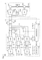
- Fig. 2 is a schematic configuration diagram of converters 6-1, 6-2 according to the first embodiment of the present invention.
- first converter 6-1 is configured to include a chopper circuit 40-1 and a smoothing capacitor C1.
- Chopper circuit 40-1 follows switching command PWC1 from converter ECU 30 ( Fig. 1 ) to step up the DC power (drive electric power) received from first power storage device 4-1 for discharging, and steps down the DC power (regenerative electric power) received from main positive line MPL and main negative line MNL for charging.
- Chopper circuit 40-1 includes a positive line LN1A, a negative line LN1C, a line LN1B, transistors Q1A, Q1B that are switching devices, diodes D1A, D1B, and an inductor L1.
- Positive line LN1A has one end connected to the collector of transistor Q1B, and the other end connected to main positive line MPL.
- Negative line LN1C has one end connected to negative line NL1 and the other end connected to main negative line MNL.
- Transistors Q1A and Q1B are connected in series between negative line LN1C and positive line LN1A.
- the emitter of transistor Q1A is connected to negative line LN1C
- the collector of transistor Q1B is connected to positive line LN1A.
- diodes D1A and D1B allowing electric current to flow from the emitter to the collector are connected, respectively.
- inductor L1 is connected to a point of connection between transistor Q1A and transistor Q1B.
- Line LN1B has one end connected to positive line PL1 and the other end connected to inductor L1.
- Smoothing capacitor C1 is connected between line LN1B and negative line LN1C and reduces an AC component included in the DC voltage between line LN1B and negative line LN1C.
- converter ECU 30 keeps transistor Q1B in the OFF state and causes transistor Q1A to be turned on and off at a predetermined duty ratio.
- discharge current flows from first power storage device 4-1 via line LN1B, inductor L1, diode D1B, and positive line LN1A in this order to main positive line MPL.
- pump current flows from first power storage device 4-1 via line LN1B, inductor L1, transistor Q1A, and negative line LN1C in this order.
- Inductor L1 accumulates electromagnetic energy by this pump current. Subsequently, transistor Q1A changes from the ON state to the OFF state. Then, inductor L1 superimposes the accumulated electromagnetic energy on discharge current. As a result, the average voltage of DC electric power supplied from first converter 6-1 to main positive line MPL and main negative line MNL is stepped up by a voltage corresponding to the electromagnetic energy accumulated in inductor L1 in accordance with the duty ratio.
- converter ECU 30 causes transistor Q1B to turn on and off at a predetermined duty ratio and keeps transistor Q1A in the OFF state.
- charge current flows from main positive line MPL via positive line LN1A, transistor Q1B, inductor L1, and line LN1B in this order to first power storage device 4-1.
- transistor Q1B changes from the ON state to the OFF state.
- inductor L1 generates a magnetic flux to hinder a change in electric current. The charge current thus continues flowing via diode D1A, inductor L1, and line LN1B in this order.
- the average voltage of the DC power supplied from first converter 6-1 to first power storage device 4-1 is a value determined by multiplying the DC voltage between main positive line MPL and main negative line MNL by the duty ratio.
- converter ECU 30 In order to control such a voltage converting operation of first converter 6-1, converter ECU 30 generates switching command PWC1 including switching command PWC1A for controlling ON and OFF of transistor Q1A and switching command PWC1B for controlling ON and OFF of transistor Q1B.
- Second converter 6-2 is configured and operates similarly to first converter 6-1 as described above, and the detailed description will not be repeated.
- Converter ECU 30 controls the voltage converting operation of converters 6-1, 6-2 following the principle illustrated in Fig. 3 .
- Fig. 3 is a diagram generally showing supply of electric power to drive force generation unit 2, according to the first embodiment of the present invention.
- Fig. 3 (a) shows the case where an electric power value (required electric power) Ps required by drive force generation unit 2 is relatively high, and
- Fig. 3 (b) shows the case where required electric power Ps is relatively low.
- first converter 6-1 operates as “master” and second converter 6-2 operates as “slave”.
- First converter 6-1 operating as “master” is controlled in accordance with "voltage control mode (voltage step up)" for setting the voltage value of the electric power supplied from power supply system 1 to drive force generation unit 2 (input/output voltage value Vh between main positive line MPL and main negative line MNL) to a predetermined target voltage value.
- second converter 6-2 operating as “slave” is controlled in accordance with "electric power control mode" for setting electric power to be shared by relevant second power storage device 4-2, of the electric power to be supplied from power supply system 1 to drive force generation unit 2 (electric power supplied and received between second power storage device 4-2 and main positive line MPL and main negative line MNL) to a predetermined target electric power value.
- discharged electric power Pb2 from second power storage device 4-2 can be adjusted in an arbitrary manner, and therefore, discharged electric power Pb1 from first power storage device 4-1 can indirectly be controlled.
- Threshold value Pth is set in accordance with allowable charge/discharge electric power of first power storage device 4-1 and second power storage device 4-2. Specifically, if required electric power Ps required by drive force generation unit 2 is smaller than the allowable charge/discharge electric power of power storage device 4-1 or 4-2, converter ECU 30 stops the voltage converting operation of one of the converters to reduce the electric power conversion loss.
- converter ECU 30 selects the converter associated with one of power storage devices 4-1, 4-2 that has a higher output voltage, and causes the converter to perform the voltage converting operation. This is for the purpose of suppressing generation of short-circuit current between the power storage devices and avoiding abnormal degradation and unwanted loss of the power storage devices. In other words, if the output voltage of the power storage device connected to the converter which is being stopped from performing the voltage converting operation is larger than the output voltage of the other power storage device, short-circuit current is generated to reverse through the converter which is being stopped from performing the voltage converting operation.
- first converter 6-1 is switched to an electrically conductive mode and second converter 6-2 is switched to a stop mode. Namely, first converter 6-1 keeps an electrically conductive state between first power storage device 4-1 and main positive line MPL and main negative line MNL. Second converter 6-2 stops performing the voltage converting operation.
- transistor Q1B ( Fig. 2 ) connected to main positive line MPL is kept in the ON state. Namely, switching command PWC1B with a duty ratio of 100% is provided from converter ECU 30 to transistor Q1B. In contrast, transistor Q1A connected to main negative line MNL is kept in the OFF state.
- switching command PWC1A with a duty ratio of 0% is provided from converter ECU 30 to transistor Q1A. Accordingly, positive line PL1 is electrically connected to main positive line MPL via inductor L1 and transistor Q1B, and negative line NL1 is directly connected to main negative line MNL.
- transistor Q2B ( Fig. 2 ) connected to main positive line MPL and transistor Q2A connected to main negative line MNL are both kept in the OFF state. Namely, switching commands PWC2B, PWC2A with a duty ratio of 0% are provided from converter ECU 30 to transistors Q2B, Q2A, respectively.
- Fig. 4 is a flowchart showing a control structure of converter ECU 30 according to the first embodiment of the present invention.
- the flowchart shown in Fig. 4 may be implemented by executing a program stored in advance by converter ECU 30.
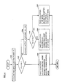
- converter ECU 30 acquires required electric power Ps from drive ECU 40 (step S01), and determines whether or not required electric power Ps is higher than threshold value Pth (step S02). Namely, it is determined whether or not the required electric power is a high load.
- converter ECU 30 sets first converter 6-1 in the voltage control mode (voltage step up) so that first converter 6-1 operates as "master”, and sets second converter 6-2 in the electric power control mode so that second converter 6-2 operates as "slave” (step S03).
- step S02 when required electric power Ps is threshold value Pth or less (NO in step S02), namely required electric power Ps is a low load, output voltages Vb1, Vb2 of power storage devices 4-1, 4-2 are acquired respectively from output voltage detection units 12-1, 12-2 ( Fig. 1 ) (step S04). Then, converter ECU 30 determines whether or not output voltage Vb1 of first power storage device 4-1 is higher than output voltage Vb2 of second power storage device 4-2 (step S05).
- converter ECU 30 switches first converter 6-1 to the electrically conductive mode and switches second converter 6-2 to the stop mode (step S06).
- converter ECU 30 switches first converter 6-1 to the stop mode and switches second converter 6-2 to the electrically conductive mode (step S07).
- the converter associated with the power storage device of a higher output voltage is switched to the electrically conductive mode, and the converter associated with the other power storage device is switched to the stop mode.
- one of converters 6-1 and 6-2 stops performing the voltage converting operation. Therefore, a switching loss (electric power conversion loss) relevant to electric power supply from the associated power storage device to main positive line MPL and main negative line MNL can be reduced. Therefore, even if the electric power supply from one power storage device is accompanied by a relatively larger value of the electric current flowing in the associated converter, generation of an unwanted loss can be suppressed. Accordingly, the energy efficiency of power supply system 1 can be improved, and thus the total fuel consumption efficiency of vehicle 100 equipped with power supply system 1 can further be improved.
- step S05 of the process flow in Fig. 4 is carried out by a comparison between respective detected values (output voltages Vb1, Vb2) of output voltage detection units 12-1, 12-2 associated respectively with power storage devices 4-1, 4-2.
- Fig. 5 is an operating state diagram of first converter 6-1 and second converter 6-2 in the control mode shown in Fig. 3 (b) .
- converter ECU 30 switches the control mode of first converter 6-1 to the electrically conductive mode, and switches the control mode of second converter 6-2 to the stop mode, based on the result of comparison that output voltage Vb1 of first power storage device 4-1 detected by output voltage detection unit 12-1 ( Fig. 1 ) is higher than output voltage Vb2 of second power storage device 4-2 detected by output voltage detection unit 12-2 ( Fig. 1 ).
- transistor Q1B is kept in the ON state while transistor Q1A is kept in the OFF state. Accordingly, positive line PL1 is electrically connected to main positive line MPL via inductor L1 and transistor Q1B.
- transistors Q2B and Q2A are both kept in the OFF state.
- first converter 6-1 associated with first power storage device 4-1 with a relatively lower output voltage is controlled in accordance with the electrically conductive mode while second converter 6-2 associated with second power storage device 4-2 with a relatively higher output voltage is controlled in accordance with the stop mode
- an electric current path is generated through which electric current flows from second power storage device 4-2 via diode D2B of second converter 6-2, main positive line MPL, and transistor Q1B of first converter 6-1 to first power storage device 4-1.
- Flow of short-circuit current Is through this electric current path causes first power storage device 4-1 to deteriorate and causes an unwanted loss. Therefore, in order to suppress generation of short-circuit current Is between the power storage devices, it is necessary to accurately perform a comparison between respective output voltages of the power storage devices without being influenced by errors that may be included in the detected value of each output voltage detection unit.
- the voltage difference between the power storage devices is calculated by subtracting detected value Vb2 of output voltage detection unit 12-2 from detected value Vb1 of output voltage detection unit 12-1.
- output voltage detection unit 12-1 includes positive and negative maximum errors ⁇ V1
- output voltage detection unit 12-2 includes positive and negative maximum errors ⁇ V2
- the positive maximum error (+ ⁇ V1) is superimposed on detected value Vb1 of output voltage detection unit 12-1
- the negative maximum error (- ⁇ V2) is superimposed on detected value Vb2 of output voltage detection unit 12-2.
- the above-described error in the result of comparison occurs when the true voltage difference between the power storage devices falls in the voltage range defined by these two sums ⁇ and - ⁇ .
- the true voltage difference between the power storage devices is larger than sum ⁇ (corresponding to a region RGN1 in Fig. 6 ), or the true voltage difference therebetween is smaller than sum - ⁇ (corresponding to a region RGN2 in Fig. 6 )
- the result of comparison between respective voltage values of the power storage devices is accurate without being influenced by the maximum errors of the output voltage detection units.
- power supply system 1 is configured to set a voltage difference in advance so that the power supply voltage of one of the power storage devices is higher by a predetermined value than the power supply voltage of the other power storage device.
- This configuration can be implemented for example by adjusting the number of battery cells provided in the power storage devices.
- the predetermined value of this configuration is determined in accordance with errors which may be included in respective detected values of the output voltage detection units. Specifically, the predetermined value is determined so that a difference in power supply voltage between the power storage devices falls in one of regions RGN1, RGN2 that can be determined by the detected values of the output voltage detection units as shown in Fig. 6 . Namely, the predetermined value is a value larger than the sum ⁇ of the maximum error of output voltage detection unit 12-1 and the maximum error of output voltage detection unit 12-1.
- the magnitude relationship between detected values Vb1, Vb2 of output voltage detection units 12-1, 12-2 is always the same as the magnitude relationship between the true output voltages. In this way, occurrence of an error to the result of comparison between respective output voltages of the power storage devices is suppressed, and therefore, occurrence of short-circuit electric current between the power storage devices can be suppressed. Accordingly, control can be performed stably for reducing an electric power conversion loss of the voltage conversion unit.
- converter ECU 30 switches the control mode of the converter associated with one of power storage devices 4-1, 4-2 that has a higher output voltage, to the electrically conductive mode, and switches the control mode of the converter associated with the other power storage device, to the stop mode.
- the first embodiment compares, by converter ECU 30, output voltages Vb1, Vb2 detected respectively by output voltage detection units 12-1, 12-2 ( Fig. 1 ).
- the selection may be made based on output current Ib1 or Ib2 detected by output current detection unit 10-1 or 10-2 ( Fig. 1 ).
- a power supply system according to the second embodiment has the same configuration as power supply system 1 shown in Fig. 1 , and therefore the illustration and the detailed description will not be repeated here.
- Fig. 7 is a flowchart showing a control structure of converter ECU 30 according to the second embodiment of the present invention.
- the flowchart shown in Fig. 7 can be implemented by executing a program stored in advance by converter ECU 30.
- converter ECU 30 acquires required electric power Ps from drive ECU 40 (step S01), and determines whether or not required electric power Ps is larger than threshold value Pth (step S02). Namely, whether or not the required electric power is a high load is determined.
- converter ECU 30 sets first converter 6-1 in the voltage control mode (voltage step up) in order to cause first converter 6-1 to operate as "master”, and sets second converter 6-2 in the electric power control mode in order to cause second converter 6-2 to operate as "slave” (step S03).
- converter ECU 30 controls transistor Q1B of first converter 6-1 and transistor Q2B of second converter 6-2 so that these transistors are simultaneously in the ON state for a predetermined period (step S14).
- Fig. 8 shows an operating state diagram of first converter 6-1 and second converter 6-2 in the predetermined period.
- transistors Q1B, Q2B connected to main positive line MPL are both kept in the ON state. Namely, to transistors Q1B, Q2B, a switching command with a duty ratio of 100% is provided from converter ECU 30.
- transistors Q1A, Q2A connected to main negative line MNL are both kept in the OFF state. Namely, to transistors Q1A, Q2A, a switching command with a duty ratio of 0% is provided from converter ECU 30.
- first converter 6-1 and second converter 6-2 are both switched to the electrically conductive mode. Consequently, positive line PL1 is electrically connected via inductor L1 and transistor Q1B to main positive line MPL, and negative line NL1 is directly connected to main negative line MNL. Positive line PL2 is electrically connected via inductor L2 and transistor Q2B to main positive line MPL, and negative line NL1 is directly connected to main negative line MNL. Therefore, an electric current path is generated between first power storage device 4-1 and second power storage device 4-2. Through the electric current path, short-circuit current Is in accordance with a voltage difference between the power storage devices flows.
- FIG. 9 schematically shows the electric current path generated between first power storage device 4-1 and second power storage device 4-2.
- output voltage Vb1 of first power storage device 4-1 can be represented by expression (1) with electromotive force Vb1o, internal resistance R1, and electric current value Ib1 of first power storage device 4-1.
- Vb ⁇ 1 Vb ⁇ 1 ⁇ o - R ⁇ 1 ⁇ Ib ⁇ 1
- output voltage Vb2 of second power storage device 4-2 can be represented by expression (2) with electromotive force Vb2o, internal resistance R2, and electric current value Ib2 of second power storage device 4-2.
- Vb ⁇ 2 Vb ⁇ 2 ⁇ o - R ⁇ 2 ⁇ Ib ⁇ 2
- the direction (polarity) of short-circuit current Is varies depending on the magnitude relationship between respective electromotive forces of the power storage devices. Specifically, when electromotive force Vb1o is larger than electromotive force Vb2o, short-circuit current Is flows from first power storage device 4-1 toward second power storage device 4-2. In contrast, when electromotive force Vb2o is larger than electromotive force Vb1o, short-circuit current Is flows from second power storage device 4-2 toward first power storage device 4-1. Therefore, a current sensor used for detecting the direction of short-circuit current Is may be provided on the electric current path as shown in Fig. 9 to determine the magnitude relationship between electromotive forces Vb1o, Vb2o based on the detected value of the current sensor.
- one of output current detection units 10-1, 10-2 associated respectively with power storage devices 4-1, 4-2 for detecting the output currents of the associated power storage devices may be used.
- the magnitude relationship between respective output voltages of the power storage devices is determined based on the direction (polarity) of the output current Ib1 detected by output current detection unit 10-1.
- the direction of output current Ib1 flowing from first power storage device 4-1 to positive line PL1 is defined as positive, and the direction of the output current flowing from positive line PL1 to first power storage device 4-1 is defined as negative.
- converter ECU 30 acquires output current Ib1 from output current detection unit 10-1 in a predetermined period of step S14 (step S15), and then determines whether the acquired output current Ib1 is positive (step S16).
- converter ECU 30 determines that output voltage Vb1 of first power storage device 4-1 is larger than output voltage Vb2 of second power storage device 4-2. Converter ECU 30 then switches first converter 6-1 to the electrically conductive mode, and switches second converter 6-2 to the stop mode (step S17).
- converter ECU 30 determines that output voltage Vb1 of second power storage device 4-2 is equal to or larger than output voltage Vb2 of first power storage device 4-1. In this case, converter ECU 30 switches first converter 6-1 to the stop mode and switches second converter 6-2 to the electrically conductive mode (step S18).
- the converter associated with one of power storage devices 4-1 and 4-2 that has a higher output voltage is switched to the electrically conductive mode, while the converter associated with the other power storage device is switched to the stop mode, which is similar to the first embodiment.
- supply of electric power to drive force generation unit 2 is continued while one of converters 6-1, 6-2 stops performing the voltage converting operation, and accordingly a switching loss in supply of electric power from the associated power storage device to main positive line MPL and main negative line MNL can be reduced.
- output current Ib1 of output current detection unit 10-1 includes an error
- the polarity of the detected value and that of the true output current may not be identical to each other.
- the control mode of converters 6-1, 6-2 is switched based on the wrong detected value, resulting in occurrence of short-circuit current Is ( Fig. 5 ) between first power storage device 4-1 and second power storage device 4-2.
- the power supply system of the second embodiment is configured to provide a predetermined voltage difference, which is determined in accordance with an error that may be included in the detected value of output current detection unit 10-1, between respective power supply voltages of power storage devices 4-1, 4-2.
- power storage devices 4-1, 4-2 are configured so that the power supply voltage of one of power storage devices 4-1, 4-2 is higher by a predetermined value than the power supply voltage of the other power storage device.
- output current detection unit 10-1 includes positive and negative maximum errors ⁇ I. Then, when detected value Ib1 of output current detection unit 10-1 falls in the range of not less than - ⁇ I and not more than + ⁇ I, the direction (polarity) of detected value Ib1 may not be identical to the direction (polarity) of the true output current. Therefore, if a comparison is made between respective output voltages of the power storage devices based on this detected value Ib1, the result of comparison should be in error.
- the predetermined value is set larger than value ⁇ which is a voltage difference between the power storage devices into which maximum error ⁇ I of output current detection unit 10-1 is converted. Then, regardless of an error which may be included in the detected value of output current detection unit 10-1, the magnitude relationship between respective output voltages of the power storage devices obtained from detected value Ib1 is always identical to that of the true output voltages. Thus, occurrence of an error in the result of comparison between respective output voltages of the power storage devices is suppressed, and therefore generation of the short-circuit current between the power storage devices can be suppressed. Consequently, control for reducing an electric power conversion loss of the voltage conversion unit can stably be carried out.
- Fig. 11 is a schematic configuration diagram showing main components of a vehicle 100 mounted with a power supply system 1A according to a third embodiment of the present invention.
- Power supply system 1A of the third embodiment differs from power supply system 1 shown in Fig. 1 in that the former includes three power storage devices 4-1 to 4-3 instead of two power storage devices 4-1, 4-2.
- power supply system 1A includes a smoothing capacitor C, an input/output voltage detection unit 14, a first converter 6-1, a second converter 6-2, a third converter 6-3, output current detection units 10-1 to 10-3, output voltage detection units 12-1 to 12-3, temperature detection units 11-1 to 11-3, a converter ECU 30A, and a battery ECU 20A.
- First converter 6-1, second converter 6-2, and third converter 6-3 are connected in parallel to each other to main positive line MPL and main negative line MNL.
- First converter 6-1 is provided between main positive line MPL and main negative line MNL, and first power storage device 4-1, and performs an electric power converting operation between first power storage device 4-1 and main positive line MPL and main negative line MNL, based on switching command PWC1 from converter ECU 30A.
- Second converter 6-2 is provided between main positive line MPL and main negative line MNL, and second power storage device 4-2, and performs an electric power converting operation between second power storage device 4-2 and main positive line MPL and main negative line MNL based on switching command PWC2 from converter ECU 30A.
- Third converter 6-3 is provided between main positive line MPL and main negative line MNL, and third power storage device 4-3, and performs an electric power converting operation between third power storage device 4-3 and main positive line MPL and main negative line MNL based on switching command PWC3 from converter ECU 30A.
- a switch device 16 is provided between main positive line MPL and main negative line MNL and converters 6-1 to 6-3 and configured to be capable of electrically disconnecting one of converters 6-1 to 6-3 from main positive line MPL and main negative line MNL, following switching command SW from converter ECU 30A.
- switch device 16 includes system relays RY1 to RY3.
- System relay RY1 is disposed between first power storage device 4-1 and first converter 6-1.
- System relay RY2 is disposed between second power storage device 4-2 and second converter 6-2.
- System relay RY3 is disposed between third power storage device 4-3 and third converter 6-3.
- System relays RY1 to RY3 are shut off in response to switch command SW from converter ECU 30A.
- Third power storage device 4-3 is a chargeable and dischargeable DC power supply.
- Output current detection unit 10-3 provided on positive line PL3 detects output current Ib3 relevant to input and output of third power storage device 4-2, and output voltage detection unit 12-3 connected between positive line PL3 and negative line NL3 detects output voltage Vb3 relevant to input and output of third power storage device 4-3.
- temperature detection unit 11-3 disposed near a battery cell forming third power storage device 4-3 detects temperature Tb3 of third power storage device 4-3.
- Battery ECU 20A calculates respective SOCs of the power storage devices based on temperatures Tb1 to Tb3 detected by temperature detection units 11-1 to 11-3, output currents Ib1 to Ib3 detected by output current detection units 10-1 to 10-3, and output voltages Vb1 to Vb3 detected by output voltage detection units 12-1 to 12-3.
- Converter ECU 30A cooperates with battery ECU 20A and drive ECU 40 connected via a control line to control the voltage converting operation of converters 6-1 to 6-3 each so that required electric power Ps may be shared at a predetermined ratio between power storage devices 4-1 to 4-3. Specifically, based on respective detected values of output current detection units 10-1 to 10-3, output voltage detection units 12-1 to 12-3, and input/output voltage detection unit 14 as well as required electric power Ps, converter ECU 30A generates switching commands PWC1 to PWC3 for driving converters 6-1 to 6-3, respectively. Then, converter ECU 30A outputs generated switching commands PWC1 to PWC3 to converters 6-1 to 6-3 respectively to control converters 6-1 to 6-3.
- converter ECU 30A when required electric power Ps is a low load, converter ECU 30A generates switch command SW for electrically disconnecting one of converters 6-1 to 6-3 from main positive line MPL and main negative line MNL, and outputs the generated switch command to switch device 16. Then, respective control modes of the converters are switched so that one of the remaining two converters executes the voltage converting operation and the voltage converting operation of the other converter is stopped.
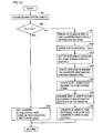
- Fig. 12 is a flowchart showing a control structure of converter ECU 30A according to the third embodiment of the present invention.
- the flowchart shown in Fig. 12 can be implemented by executing a program stored in advance by converter ECU 30A.
- converter ECU 30A acquires required electric power Ps from drive ECU 40 (step S01), and determines whether or not required electric power Ps is larger than threshold value Pth (step S02). Namely, it is determined whether or not the required electric power is a high load.
- converter ECU 30A sets first converter 6-1 in the voltage control mode (voltage step up) so that first converter 6-1 is caused to operate as "master”, and sets second converter 6-2 and third converter 6-3 in the electric power control mode so that second converter 6-2 and third converter 6-3 are caused to operate as "slave” (step S03).
- converter ECU 30A controls the transistors constituting respective upper arms of converters 6-1 to 6-3 so that they are simultaneously set in the ON state for a predetermined period (step S21).
- Pth threshold value
- converters 6-1 to 6-3 are all controlled so that they are in the electrically conductive mode.
- Converter ECU 30A acquires output currents Ib1 to Ib3 in this predetermined period from output current detection units 10-1 to 10-3 respectively (step S22).
- converter ECU 30A Based on acquired output currents Ib1 to Ib3, converter ECU 30A selects a converter associated with a power storage device with the output current of the negative direction (polarity), and then generates switch command SW for electrically disconnecting this converter from main positive line MPL and main negative line MNL to output the command to switch device 16. In this way, the system relay provided between this converter and main positive line MPL and main negative line MNL is shut off (step S23).
- a power storage device having the lowest output voltage is selected from power storage devices 4-1 to 4-3. This is based on the fact that, in the predetermined period, an electric current path is formed between power storage devices 4-1 to 4-3 via main positive line MPL and main negative line MNL, and short-circuit current flows through this electric current path toward a power storage device with the lowest output voltage, from the remaining two power storage devices.
- converter ECU 30A performs the operations in the following steps S24 to S27 to select a converter associated with a power storage device with a relatively higher output voltage from the remaining two converters and causes the converter to perform the voltage converting operation.
- the operations in steps S24 to S27 are substantially the same as those in steps S14 to S18 of the flowchart in Fig. 7 .
- converter ECU 30A first controls the transistors constituting the upper arms of the remaining two converters associated with the remaining two power storage devices so that the transistors are simultaneously in the ON state for a predetermined period (step S24). In this predetermined period, when converter ECU 30A acquires output current Ib of one of the remaining two power storage devices from the associated output current detection unit (step S25), converter ECU 30A determines the magnitude relationship between respective output voltages of the remaining two power storage devices based on the polarity of acquired output current Ib (step S26).
- converter ECU 30A switches the converter associated with one of the power storage devices that has a higher output voltage to the electrically conductive mode, and switches the converter associated with the other power storage device to the stop mode (step S27).
- supply of electric power to drive force generation unit 2 is continued while the converters associated with the remaining power storage devices stop performing the voltage converting operation. Accordingly, a switching loss in electric power supply from the remaining power storage devices to main positive line MPL and main negative line MNL can be reduced. Therefore, even if electric power supply from only one power storage device is accompanied by a relatively large value of electric current flowing in the associated converter, occurrence of an unwanted loss can be suppressed.
- a predetermined voltage difference is defined that is determined based on errors which may be included in the detected values of the output current detection units, between respective power supply voltages of power storage devices 4-1 to 4-3.
- second power storage device 4-2 is configured to have a power supply voltage higher by a predetermined value than third power storage device 4-3.
- first power storage device 4-1 is configured to have a power supply voltage higher by a predetermined value than second power storage device 4-2.
- the predetermined value is set to a value higher than value ⁇ which is a voltage difference between the power storage devices into which maximum error ⁇ Iof the output current detection units is converted, as described in connection with Fig. 10 .
- the magnitude relationship between respective output voltages of the power storage devices that is obtained from the detected values is always the same as the magnitude relationship between the true output voltages, regardless of errors that may be included in the detected values of the output current detection units.
- occurrence of an error to the result of comparison between the output voltages of the power storage devices is suppressed, and generation of short-circuit current between the power storage devices can be suppressed.
- the power supply system is configured to include three or more power storage devices and converters, the effects similar to those of the first and second embodiments can be achieved. Therefore, in accordance with required electric power of the load device, the number of converters and power storage devices can be designed relatively freely.
- a power supply system capable of supplying electric power to load devices of various sizes and types, as well as a vehicle equipped with the power supply system can be implemented.
- the drive force generation unit including two motor generators is used as an example of the load device.
- the number of motor generators is not limited.
- the load device is not limited to the drive force generation unit generating a force for driving a vehicle, and may be a device which only consumes electric power or a device which consumes electric power and is also capable of generating electric power.
- the present invention is applicable to a power supply system having a plurality of power storage devices as well as a vehicle equipped with the power supply system.
Applications Claiming Priority (1)
| Application Number | Priority Date | Filing Date | Title |
|---|---|---|---|
| PCT/JP2009/058662 WO2010128550A1 (fr) | 2009-05-08 | 2009-05-08 | Système d'alimentation en énergie et véhicule équipé d'un système d'alimentation en énergie |
Publications (2)
| Publication Number | Publication Date |
|---|---|
| EP2428388A1 true EP2428388A1 (fr) | 2012-03-14 |
| EP2428388A4 EP2428388A4 (fr) | 2014-07-16 |
Family
ID=43050063
Family Applications (1)
| Application Number | Title | Priority Date | Filing Date |
|---|---|---|---|
| EP09844337.7A Withdrawn EP2428388A4 (fr) | 2009-05-08 | 2009-05-08 | Système d'alimentation en énergie et véhicule équipé d'un système d'alimentation en énergie |
Country Status (5)
| Country | Link |
|---|---|
| US (1) | US8598734B2 (fr) |
| EP (1) | EP2428388A4 (fr) |
| JP (1) | JP5287983B2 (fr) |
| CN (1) | CN102421630B (fr) |
| WO (1) | WO2010128550A1 (fr) |
Cited By (3)
| Publication number | Priority date | Publication date | Assignee | Title |
|---|---|---|---|---|
| CN103612571A (zh) * | 2013-11-29 | 2014-03-05 | 东风小康汽车有限公司重庆分公司 | 电动汽车蓄电池故障紧急控制系统 |
| CN103963657A (zh) * | 2013-02-01 | 2014-08-06 | 丰田自动车株式会社 | 电动车辆和控制电动车辆的方法 |
| US8996227B2 (en) | 2013-01-11 | 2015-03-31 | Johnson Controls Technology Company | System and method for controlling voltage on a power network |
Families Citing this family (35)
| Publication number | Priority date | Publication date | Assignee | Title |
|---|---|---|---|---|
| EP2774797B1 (fr) * | 2011-11-04 | 2019-05-15 | Toyota Jidosha Kabushiki Kaisha | Système de bloc d'alimentation et véhicule équipé de celui-ci, et procédé de contrôle d'un système de bloc d'alimentation |
| JP6010995B2 (ja) * | 2012-04-17 | 2016-10-19 | ソニー株式会社 | 充電装置、充電装置の制御方法、電動車両、蓄電装置および電力システム |
| KR101957340B1 (ko) * | 2012-11-14 | 2019-03-12 | 삼성전자주식회사 | 전력 전달 장치. |
| JP5652622B2 (ja) * | 2013-01-08 | 2015-01-14 | 三菱自動車工業株式会社 | 車両の異常診断装置 |
| DE102013204894A1 (de) * | 2013-03-20 | 2014-09-25 | Robert Bosch Gmbh | Kraftfahrzeugbordnetz mit wenigstens zwei Energiespeichern, Verfahren zum Betreiben eines Kraftfahrzeugbordnetzes und Mittel zu dessen Implementierung |
| JP6139236B2 (ja) * | 2013-04-16 | 2017-05-31 | 株式会社東芝 | 電気機関車制御装置 |
| US9391455B2 (en) * | 2013-08-29 | 2016-07-12 | Harmonic, Inc. | System for switching between power supply units |
| KR20150091651A (ko) * | 2014-02-03 | 2015-08-12 | 삼성전자주식회사 | 전력장치 및 전력장치의 전력제공방법 |
| US9550421B2 (en) * | 2014-03-17 | 2017-01-24 | Denso International America, Inc. | DC-to-DC converter with variable set-point control |
| JP2015217920A (ja) * | 2014-05-21 | 2015-12-07 | オムロンオートモーティブエレクトロニクス株式会社 | 車両用電源装置、車両用回生システム |
| JP2015217919A (ja) * | 2014-05-21 | 2015-12-07 | オムロンオートモーティブエレクトロニクス株式会社 | 車両用電源装置、車両用回生システム |
| CN107107842B (zh) * | 2015-02-05 | 2019-08-23 | 日立汽车系统株式会社 | 车辆控制装置 |
| CN105990896A (zh) * | 2015-02-13 | 2016-10-05 | 深圳市华思旭科技有限公司 | 电源控制电路、移动电源以及电连接装置 |
| JP2017022872A (ja) * | 2015-07-10 | 2017-01-26 | トヨタ自動車株式会社 | 電源システム |
| CN108025365B (zh) * | 2015-07-17 | 2022-06-03 | Ap&C高端粉末涂料公司 | 等离子体雾化金属粉末制造工艺及其系统 |
| JP6551089B2 (ja) * | 2015-09-11 | 2019-07-31 | 株式会社オートネットワーク技術研究所 | 車載用電源装置 |
| EP3985835A1 (fr) * | 2015-09-22 | 2022-04-20 | Guangdong Oppo Mobile Telecommunications Corp., Ltd. | Procédé et dispositif de commande de charge, et dispositif électronique |
| KR102280433B1 (ko) * | 2015-09-23 | 2021-07-22 | 삼성전자주식회사 | 전력 공급 회로 및 이를 포함하는 저장 장치 |
| JP6335860B2 (ja) * | 2015-10-13 | 2018-05-30 | 本田技研工業株式会社 | 駆動装置及びその制御方法、並びに、輸送機器 |
| CN109196761B (zh) * | 2016-06-02 | 2021-01-12 | 株式会社村田制作所 | 电源系统 |
| JP6614452B2 (ja) * | 2016-06-17 | 2019-12-04 | 株式会社オートネットワーク技術研究所 | リレー装置 |
| JP6694592B2 (ja) * | 2016-07-07 | 2020-05-20 | 株式会社オートネットワーク技術研究所 | リレー装置 |
| JP6705357B2 (ja) * | 2016-10-14 | 2020-06-03 | 株式会社オートネットワーク技術研究所 | 車載用のバックアップ装置 |
| TWI624132B (zh) * | 2016-12-27 | 2018-05-11 | 飛宏科技股份有限公司 | 用於充電樁之智慧功率分配系統 |
| JP6545230B2 (ja) * | 2017-08-31 | 2019-07-17 | 本田技研工業株式会社 | 車両の電源システム |
| JP6554151B2 (ja) * | 2017-08-31 | 2019-07-31 | 本田技研工業株式会社 | 車両の電源システム |
| CN107554344B (zh) * | 2017-09-18 | 2018-05-08 | 爱驰汽车有限公司 | 双源电池包的充放电管理方法和系统 |
| WO2019058821A1 (fr) * | 2017-09-22 | 2019-03-28 | 株式会社村田製作所 | Appareil de stockage d'énergie |
| US11594895B2 (en) * | 2018-09-13 | 2023-02-28 | Honda Motor Co., Ltd. | Power supply system |
| JP7010191B2 (ja) * | 2018-10-23 | 2022-02-10 | トヨタ自動車株式会社 | 二次電池システムおよび二次電池の充電制御方法 |
| JP6935437B2 (ja) * | 2019-01-23 | 2021-09-15 | 矢崎総業株式会社 | 電源装置 |
| CN114731055A (zh) * | 2019-11-20 | 2022-07-08 | 本田技研工业株式会社 | 电源系统及其控制方法 |
| KR20220153401A (ko) * | 2021-05-11 | 2022-11-18 | 현대자동차주식회사 | 전기구동 모빌리티의 전력 변환 시스템 및 그 제어 방법 |
| US11837984B2 (en) * | 2021-05-14 | 2023-12-05 | Delphi Technologies Ip Limited | Dual supply dual control architecture |
| CN114498866B (zh) * | 2022-04-19 | 2022-07-29 | 伏达半导体(合肥)有限公司 | 双电池充电装置、方法及其控制器 |
Citations (2)
| Publication number | Priority date | Publication date | Assignee | Title |
|---|---|---|---|---|
| WO2008004464A1 (fr) * | 2006-07-03 | 2008-01-10 | Toyota Jidosha Kabushiki Kaisha | Convertisseur de tension et véhicule équipé du convertisseur de tension |
| WO2008146577A1 (fr) * | 2007-05-23 | 2008-12-04 | Toyota Jidosha Kabushiki Kaisha | Système destiné à commander un dispositif monté sur un véhicule et véhicule |
Family Cites Families (13)
| Publication number | Priority date | Publication date | Assignee | Title |
|---|---|---|---|---|
| US5373195A (en) | 1992-12-23 | 1994-12-13 | General Electric Company | Technique for decoupling the energy storage system voltage from the DC link voltage in AC electric drive systems |
| JPH07115704A (ja) * | 1993-10-14 | 1995-05-02 | Toyota Motor Corp | リターダ装置 |
| US6608396B2 (en) | 2001-12-06 | 2003-08-19 | General Motors Corporation | Electrical motor power management system |
| JP2004116296A (ja) * | 2002-09-24 | 2004-04-15 | Honda Motor Co Ltd | 車両用電源装置 |
| CA2459696A1 (fr) * | 2004-03-04 | 2005-09-04 | Tm4 Inc. | Systeme et methode de demarrage d'un moteur a combustion d'un vehicule hybride |
| JP2006252445A (ja) * | 2005-03-14 | 2006-09-21 | Fujitsu Ltd | データ記憶装置及びデータ記憶装置のライト処理方法。 |
| JP2006304390A (ja) * | 2005-04-15 | 2006-11-02 | Favess Co Ltd | ハイブリッド車両用電源装置 |
| WO2007006121A1 (fr) * | 2005-04-20 | 2007-01-18 | Mountain Power Inc. | Detection de l'etat de charge d'une batterie lithium-ion dans un vehicule electrique hybride |
| JP2007295720A (ja) * | 2006-04-25 | 2007-11-08 | Denso Corp | 車両用モータ装置 |
| JP4179351B2 (ja) | 2006-07-07 | 2008-11-12 | トヨタ自動車株式会社 | 電源システムおよびそれを備えた車両、電源システムの制御方法、ならびに電源システムの制御をコンピュータに実行させるためのプログラムを記録したコンピュータ読取可能な記録媒体 |
| JP4466620B2 (ja) * | 2006-07-10 | 2010-05-26 | トヨタ自動車株式会社 | 電源システムおよびそれを備える車両 |
| JP4450004B2 (ja) * | 2007-03-30 | 2010-04-14 | トヨタ自動車株式会社 | 電源回路の制御装置および制御方法 |
| US20090033253A1 (en) * | 2007-07-30 | 2009-02-05 | Gm Global Technology Operations, Inc. | Electric traction system for a vehicle having a dual winding ac traction motor |
-
2009
- 2009-05-08 EP EP09844337.7A patent/EP2428388A4/fr not_active Withdrawn
- 2009-05-08 JP JP2011512282A patent/JP5287983B2/ja not_active Expired - Fee Related
- 2009-05-08 US US13/259,416 patent/US8598734B2/en active Active
- 2009-05-08 CN CN200980159164.6A patent/CN102421630B/zh active Active
- 2009-05-08 WO PCT/JP2009/058662 patent/WO2010128550A1/fr active Application Filing
Patent Citations (2)
| Publication number | Priority date | Publication date | Assignee | Title |
|---|---|---|---|---|
| WO2008004464A1 (fr) * | 2006-07-03 | 2008-01-10 | Toyota Jidosha Kabushiki Kaisha | Convertisseur de tension et véhicule équipé du convertisseur de tension |
| WO2008146577A1 (fr) * | 2007-05-23 | 2008-12-04 | Toyota Jidosha Kabushiki Kaisha | Système destiné à commander un dispositif monté sur un véhicule et véhicule |
Non-Patent Citations (1)
| Title |
|---|
| See also references of WO2010128550A1 * |
Cited By (4)
| Publication number | Priority date | Publication date | Assignee | Title |
|---|---|---|---|---|
| US8996227B2 (en) | 2013-01-11 | 2015-03-31 | Johnson Controls Technology Company | System and method for controlling voltage on a power network |
| CN103963657A (zh) * | 2013-02-01 | 2014-08-06 | 丰田自动车株式会社 | 电动车辆和控制电动车辆的方法 |
| CN103612571A (zh) * | 2013-11-29 | 2014-03-05 | 东风小康汽车有限公司重庆分公司 | 电动汽车蓄电池故障紧急控制系统 |
| CN103612571B (zh) * | 2013-11-29 | 2016-01-20 | 东风小康汽车有限公司重庆分公司 | 电动汽车蓄电池故障紧急控制系统 |
Also Published As
| Publication number | Publication date |
|---|---|
| EP2428388A4 (fr) | 2014-07-16 |
| US8598734B2 (en) | 2013-12-03 |
| CN102421630B (zh) | 2014-05-21 |
| US20120032505A1 (en) | 2012-02-09 |
| CN102421630A (zh) | 2012-04-18 |
| WO2010128550A1 (fr) | 2010-11-11 |
| JP5287983B2 (ja) | 2013-09-11 |
| JPWO2010128550A1 (ja) | 2012-11-01 |
Similar Documents
| Publication | Publication Date | Title |
|---|---|---|
| EP2428388A1 (fr) | Système d'alimentation en énergie et véhicule équipé d'un système d'alimentation en énergie | |
| US11318852B2 (en) | Method and apparatus for charging multiple energy storage devices | |
| JP6130634B2 (ja) | 電気車両を充電するための装置および方法 | |
| JP4501893B2 (ja) | 電源システムおよび車両 | |
| EP2202872B1 (fr) | Alimentation, voiture equipee de cette alimentation, procede de controle de l'alimentation et support d'enregistrement lisible par ordinateur qui enregistre un programme permettant a l'ordinateur d'executer le procede de controle | |
| US8829722B2 (en) | Apparatus and method for rapidly charging an electric vehicle | |
| JP2017169311A (ja) | 駆動装置、輸送機器及び制御方法 | |
| EP2154772A1 (fr) | Systeme d'alimentation, vehicule l'utilisant, procede de commande de systeme d'alimentation et support d'enregistrement lisible par ordinateur contenant le programme pour amener un ordinateur a executer le procede de commande | |
| JP2010124536A (ja) | 車両の電源システムおよび車両 | |
| JP5109958B2 (ja) | 電源システムおよびそれを備えた車両、ならびに電源システムの制御方法 | |
| JP2010004667A (ja) | 電源システム | |
| JP2010136553A (ja) | 電源システムおよびそれを搭載した電動車両 | |
| JP2009284668A (ja) | 電源システムおよびそれを備えた車両 | |
| JP5267092B2 (ja) | 電源システムおよびそれを備えた車両、ならびに電源システムの制御方法 | |
| JP6492001B2 (ja) | 駆動装置、輸送機器及び制御方法 | |
| JP2017169312A (ja) | 駆動装置、輸送機器及び制御方法 |
Legal Events
| Date | Code | Title | Description |
|---|---|---|---|
| PUAI | Public reference made under article 153(3) epc to a published international application that has entered the european phase |
Free format text: ORIGINAL CODE: 0009012 |
|
| 17P | Request for examination filed |
Effective date: 20111207 |
|
| AK | Designated contracting states |
Kind code of ref document: A1 Designated state(s): AT BE BG CH CY CZ DE DK EE ES FI FR GB GR HR HU IE IS IT LI LT LU LV MC MK MT NL NO PL PT RO SE SI SK TR |
|
| DAX | Request for extension of the european patent (deleted) | ||
| RAP1 | Party data changed (applicant data changed or rights of an application transferred) |
Owner name: TOYOTA JIDOSHA KABUSHIKI KAISHA |
|
| A4 | Supplementary search report drawn up and despatched |
Effective date: 20140616 |
|
| RIC1 | Information provided on ipc code assigned before grant |
Ipc: B60L 11/18 20060101AFI20140610BHEP Ipc: H02J 7/00 20060101ALI20140610BHEP Ipc: B60L 3/00 20060101ALI20140610BHEP Ipc: B60L 9/18 20060101ALI20140610BHEP |
|
| 17Q | First examination report despatched |
Effective date: 20151223 |
|
| STAA | Information on the status of an ep patent application or granted ep patent |
Free format text: STATUS: EXAMINATION IS IN PROGRESS |
|
| STAA | Information on the status of an ep patent application or granted ep patent |
Free format text: STATUS: THE APPLICATION HAS BEEN WITHDRAWN |
|
| 18W | Application withdrawn |
Effective date: 20170815 |