EP2426573A2 - Electronic apparatus - Google Patents
Electronic apparatus Download PDFInfo
- Publication number
- EP2426573A2 EP2426573A2 EP11179292A EP11179292A EP2426573A2 EP 2426573 A2 EP2426573 A2 EP 2426573A2 EP 11179292 A EP11179292 A EP 11179292A EP 11179292 A EP11179292 A EP 11179292A EP 2426573 A2 EP2426573 A2 EP 2426573A2
- Authority
- EP
- European Patent Office
- Prior art keywords
- casing
- face
- hinge
- section
- electronic apparatus
- Prior art date
- Legal status (The legal status is an assumption and is not a legal conclusion. Google has not performed a legal analysis and makes no representation as to the accuracy of the status listed.)
- Withdrawn
Links
Images


Classifications
-
- G—PHYSICS
- G06—COMPUTING OR CALCULATING; COUNTING
- G06F—ELECTRIC DIGITAL DATA PROCESSING
- G06F1/00—Details not covered by groups G06F3/00 - G06F13/00 and G06F21/00
- G06F1/16—Constructional details or arrangements
- G06F1/1613—Constructional details or arrangements for portable computers
- G06F1/1633—Constructional details or arrangements of portable computers not specific to the type of enclosures covered by groups G06F1/1615 - G06F1/1626
- G06F1/1675—Miscellaneous details related to the relative movement between the different enclosures or enclosure parts
- G06F1/1681—Details related solely to hinges
-
- H—ELECTRICITY
- H05—ELECTRIC TECHNIQUES NOT OTHERWISE PROVIDED FOR
- H05K—PRINTED CIRCUITS; CASINGS OR CONSTRUCTIONAL DETAILS OF ELECTRIC APPARATUS; MANUFACTURE OF ASSEMBLAGES OF ELECTRICAL COMPONENTS
- H05K5/00—Casings, cabinets or drawers for electric apparatus
- H05K5/02—Details
- H05K5/0217—Mechanical details of casings
- H05K5/0226—Hinges
Definitions
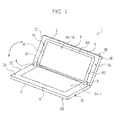
- the present invention relates to a folding-type electronic apparatus formed by connecting a first casing and a second casing which can be opened and closed.
- a first member provided with operation keys and a second member provided with a display are connected to each other through a hinge device.
- a first turning shaft section and a second turning shaft section are provided in parallel with each other in the hinge device, the first member is pivotally mounted on the first turning shaft section so as to be able to turn, and also the second member is pivotally mounted on the second turning shaft section so as to be able to turn.
- a first turning section and a second turning section which turn relative to each other are respectively provided at the first turning shaft section and the second turning shaft section. Further, in the hinge device, the first turning section and the second turning section are connected to each other by an interlocking link.
- the electronic apparatus is made such that the first member and the second member can turn through 360 degrees relative to each other through the hinge device (refer to Japanese Unexamined Patent Application Publication 2008-75747 (Pages 8 to 10 and Figs. 7 to 13 ), for example).
- a folding-type electronic apparatus of this kind if the first member and the second member are opened and an operation key is pressed, a variety of processes are executed in accordance with the operation, and information indicating the execution status of the process is displayed on the display.
- the folding-type electronic apparatus in a situation where the first member and the second member are opened and the operation key is then operated, the execution status of a process according to the operation is appropriately ascertained through the display.
- the operation key and the display are correspondingly far away from each other. For this reason, in the folding-type electronic apparatus, it may not be said that it is possible to make the amount of eye movement between the operation key and the display small in order to reduce eyestrain when the first member and the second member are opened and the operation key is then operated.
- an electronic apparatus in which a first casing and a second casing are connected to each other by a hinge section which includes a first turning shaft provided at a first casing one end portion of the first casing and a second turning shaft provided at a second casing one end portion of the second casing, so as to be able to be opened and closed in a range from a folded state to a back-to-back state through the first turning shaft and the second turning shaft, and by a displacement section, a display section provided on a second casing one face of the second casing is displaced to a second casing other end side in the folded state and the back-to-back state of the first casing and the second casing and displaced to a second casing one end side in a spread state of the first casing and the second casing.
- the hinge section which includes the first turning shaft provided at the first casing one end portion of the first casing and the second turning shaft provided at the second casing one end portion of the second casing, so as to be able to be opened and closed in a range from the folded state to the back-to-back state through the first turning shaft and the second turning shaft, and such that by the displacement section, the display section provided on the second casing one face of the second casing is displaced to the second casing other end side in the folded state and the back-to-back state of the first casing and the second casing and displaced to the second casing one end side in the spread state of the first casing and the second casing, in a situation where the display surface or the operation keys in the first casing one face and the display surface in the second casing one face is visually observed in the spread state of the first casing and the second casing, the amount of eye movement between the display surface or the operation keys in the first
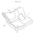
- reference numeral 1 generally denotes a folding-type electronic apparatus according to an embodiment of the invention.
- first casing 2 of an approximately flat rectangular shape and one end portion of a second casing 3 of an approximately flat rectangular shape are connected to each other through first and second hinge sections 4 and 5 each having a two-shaft configuration.
- the electronic apparatus 1 is formed such that the first casing 2 and the second casing 3 can be opened or closed in a range of 0 degrees to 360 degrees from a folded state where each of one faces 2A and 3A are matched to each other to a back-to-back state where each of other faces 2B and 3B are matched to each other.
- one end of the first casing 2 is also referred to as a first casing one end and the other end on the opposite side to the first casing one end in the first casing 2 is also referred to as a first casing other end.
- a direction from the first casing one end toward the first casing other end in the first casing 2 and a direction from the first casing other end toward the first casing one end, which is opposite to the above direction, are also collectively referred to as a first casing depth direction.
- one face 2A of the first casing 2 is also referred to as a first casing one face 2A and the other face 2B of the first casing 2 is also referred to as a first casing other face 2B.
- a direction from the first casing one face 2A toward the first casing other face 2B in the first casing 2 and a direction from the first casing other face 2B toward the first casing one face 2A, which is opposite to the above direction, are also collectively referred to as a first casing thickness direction.
- a side face 2C on one side of the first casing 2 is also referred to as a first casing left side face 2C and a side face 2D on the other side of the first casing 2 is also referred to as a first casing right side face 2D.
- a direction from the first casing left side face 2C toward the first casing right side face 2D in the first casing 2 and a direction from the first casing right side face 2D toward the first casing left side face 2C, which is opposite to the above direction, are also collectively referred to as a first casing width direction.
- one end of the second casing 3 is also referred to as a second casing one end and the other end on the opposite to the second casing one end in the second casing 3 is also referred to as a second casing other end.
- a direction from the second casing one end toward the second casing other end in the second casing 3 and a direction from the second casing other end toward the second casing one end, which is opposite to the above direction, are also collectively referred to as a second casing depth direction.
- one face 3A of the second casing 3 is also referred to as a second casing one face 3A and the other face 3B of the second casing 3 is also referred to as a second casing other face 3B.
- a direction from the second casing one face 3A toward the second casing other face 3B in the second casing 3 and a direction from the second casing other face 3B toward the second casing one face 3A, which is opposite to the above direction, are also collectively referred to as a second casing thickness direction.
- a side face 3C on one side of the second casing 3 is also referred to as a second casing left side face 3C and a side face 3D on the other side of the second casing 3 is also referred to as a second casing right side face 3D.
- a direction from the second casing left side face 3C toward the second casing right side face 3D in the second casing 3 and a direction from the second casing right side face 3D toward the second casing left side face 3C, which is opposite to the above direction, are also collectively referred to as a second casing width direction.
- first casing 2 and the second casing 3 are selected so as to be equal in shape, size, and thickness to each other.
- the thicknesses of the first casing 2 and the second casing 3 are also referred to as a casing thickness.
- a first display section 6 of an approximately flat rectangular shape is disposed over an area from the vicinity (for example, a position several mm away from the first casing one end toward the first casing other end) of the first casing one end to a given position on the first casing other end side in a state where a first display surface 6A is exposed.
- one end on the first casing one end side is also referred to as a first display surface one end and the other end on the first casing other end side is also referred to as a first display surface other end.
- the distance from the first casing one end to the first display surface one end in the central portion of the first casing one face 2A is selected so as to be the above-mentioned several mm, so that the first display section 6 is disposed in a state where the first display surface one end is close to the first casing one end.
- a first transparent touch panel 7 is provided on the first display surface 6A of the first display section 6 so as to cover the first display surface 6A.
- the first display section 6 provided on the first casing one face 2A of the first casing 2 is a liquid crystal display, an organic EL (Electro Luminescence) display, or the like.
- an approximately rectangular cutout portion for display section displacement (hereinafter, this is also referred to as a cutout portion for displacement) 3E is formed over an area from the second casing one end to a given position on the second casing other end side.
- a holding section 8 formed into an approximately rectangular frame shape is provided so as to be able to slide in the second casing depth direction.
- the holding section 8 holds a second display section 9 of an approximately flat rectangular shape so as to surround the side face thereof over the entire periphery, thereby exposing a second display surface 9A of the second display section 9 in the second casing one face 3A.
- one end on the second casing one end side is also referred to as a second display surface one end and the other end on the second casing other end side is also referred to as a second display surface other end.
- the depth of a frame portion 8A on the second casing one end side (that is, contacting the second display surface one end) among four frame portions 8A to 8D surrounding the side face of the second display section 9 over the entire periphery is selected so as to be several mm that is equal to the distance from the first casing one end to the first display surface one end.
- the frame portion 8A on the second casing one end side among the four frame portions 8A to 8D of the holding section 8 is also referred to as a one end-side frame portion 8A.
- the holding section 8 slides to the second casing one end side, thereby being able to bring the second display surface one end close to the first display surface one end.
- the holding section 8 brings the second display surface 9A close to the first display surface 6A, thereby allowing these display surfaces to be disposed as if they were one display surface.
- a second transparent touch panel 10 is provided so as to cover the second display surface 9A.
- the second display section 9 provided on one face 3A of the second casing 3 is also a liquid crystal display, an organic EL display, or the like.
- various circuit sections such as a control section, a storage section, or the like are housed, and the control section is electrically connected to other circuit sections.
- control section is also appropriately electrically connected to the first display section 6, the second display section 9, the first touch panel 7, and the second touch 10. Accordingly, for example, the control section can individually display different types of images on the first display surface 6A of the first display section 6 and the second display surface 9A of the display section 9.
- control can also divide a single image into two and display the two divided images on the first display surface 6A of the first display section 6 and the second display surface 9A of the second display section 9.
- control section can display a single image over the first and second display surfaces 6A and 9A by using the first and second display surfaces 6A and 9A as if they were one display surface.
- the control section executes processing according to the touch operation.
- control section can display an image with various operation keys arranged as icons (hereinafter, this is also referred to as a keyboard image) on the first display surface 6A of the first display section 6.
- the control section executes processing assigned in advance to the icon indicated by the touch operation.
- control section makes the first display surface 6A function along with the first touch panel 7 as if it were a hardware keyboard, thereby switching an image that is displayed on the second display surface 9A, in accordance to an operation on the keyboard (keyboard image), and updating the contents of the image.
- a cutout portion for a hinge 2E which has a width approximately equal to the width of a first hinge section 4 and in which the depth thereof from the first casing one end to the first casing other end side is approximately equal to the casing thickness is formed at a given position near the first casing left side face 2C.
- the cutout portion for a hinge 2E formed at a given position near the first casing left side face 2C in the first casing one end portion is also referred to as a first casing left cutout portion 2E.
- a cutout portion for a hinge 2F which has a width approximately equal to the width of a second hinge section 5 and in which the depth thereof from the first casing one end to the first casing other end side is approximately equal to the casing thickness is also formed at a given position near the first casing right side face 2D.
- the cutout portion for a hinge 2F formed at a given position near the first casing right side face 2D in the first casing one end portion is also referred to as a first casing right cutout portion 2F.
- the portion between the first casing left cutout portion 2E and the first casing right cutout portion 2F in the first casing one end is formed into a planar shape in which an end face (that is, an end face of the first casing one end) 2G contacts the first casing one face 2A and the first casing other face 2B at right angles.
- first casing one end central portion the portion between the first casing left cutout portion 2E and the first casing right cutout portion 2F in the first casing one end is also referred to as a first casing one end central portion and the end face 2G of the first casing one end central portion is also referred to as a first casing one end face 2G.
- a portion 2H further on the first casing left side face 2C side than the first casing left cutout portion 2E in the first casing one end portion becomes a shaft formation portion in which a turning shaft when turning the first casing 2 with respect to the second casing 3 is formed as will be described later.
- the portion 2H that is, the shaft formation portion, further on the first casing left side face 2C side than the first casing left cutout portion 2E in the first casing one end portion is also referred to as a first left shaft formation portion 2H.
- an end face thereof on the first casing one end side is formed into an arc shape which follows a side face corresponding to the semicircle of a cylinder, the radius of which is a distance of 1/2 of the casing thickness, centering around a virtual line VL1 that is located in parallel with the first casing width direction and at a distance of 1/2 of the casing thickness from the center of the end face.
- a portion 2J further on the first casing right side face 2D side than the first casing right cutout portion 2F in the first casing one end portion also becomes a shaft formation portion in which a turning shaft when turning the first casing 2 with respect to the second casing 3 is formed as will be described later.
- the portion 2J that is, the shaft formation portion, further on the first casing right side face 2D side than the first casing right cutout portion 2F in the first casing one end portion is also referred to as a first right shaft formation portion 2J.
- an end face thereof on the first casing one end side is formed into an arc shape which follows a side face corresponding to the semicircle of a cylinder, the radius of which is a distance of 1/2 of the casing thickness, centering around the above-mentioned virtual line VL1, similarly to the first left shaft formation portion 2H.
- the cutout portion for displacement 3E is formed so as to leave a bottom plate 3K of the second casing 3. Further, at the second casing one end side, the cutout portion for displacement 3E is formed such that the bottom plate 3K of the second casing 3 is removed in an approximately U shape from the second casing one end to the second casing other end side.
- a cutout portion for a hinge 3F which has a width approximately equal to the width of the first hinge section 4 and in which the depth thereof from the second casing one end to the second casing other end side is approximately equal to the casing thickness is formed at a given position near the second casing left side face 3C, which faces the first casing left cutout portion 2E.
- the cutout portion for a hinge 3F formed at a given position near the second casing left side face 3C in the second casing one end portion is also referred to as a second casing left cutout portion 3F.
- the second casing left cutout portion 3F is formed so as to face the above-mentioned first casing left cutout portion 2E at a portion actually cut out in the second casing one end portion and a portion related to the left side of the cutout portion for displacement 3E.
- a cutout portion for a hinge 3G in which the depth thereof from the second casing one end to the second casing other end side is approximately equal to the casing thickness is also formed facing the above-mentioned first casing right cutout portion 2F at a given position near the second casing right side face 3D.
- the cutout portion for a hinge 3G formed at a given position near the second casing right side face 3D in the second casing one end portion is also referred to as a second casing right cutout portion 3G.
- the second casing right cutout portion 3G is formed so as to face the above-mentioned first casing right cutout portion 2F at a portion actually cut out in the second casing one end portion and a portion related to the right side of the cutout portion for displacement 3E.
- a portion 3H further on the second casing left side face 3C side than the second casing left cutout portion 3F in the second casing one end portion becomes a shaft formation portion in which a turning shaft when turning the second casing 3 with respect to the first casing 2 is formed as will be described later.
- the portion 3H that is, the shaft formation portion, further on the second casing left side face 3C side than the second casing left cutout portion 3F in the second casing one end portion is also referred to as a second left shaft formation portion 3H.
- an end face thereof on the second casing one end side is formed into an arc shape which follows a side face corresponding to the semicircle of a cylinder, the radius of which is a distance of 1/2 of the casing thickness, centering around a virtual line VL2 that is located in parallel with the second casing width direction and at a distance of 1/2 of the casing thickness from the center of the end face.
- a portion 3J further on the second casing right side face 3D side than the second casing right cutout portion 3G in the second casing one end portion also becomes a shaft formation portion in which a turning shaft when turning the second casing 3 with respect to the first casing 2 is formed as will be described later.
- the portion 3J that is, the shaft formation portion, further on the second casing right side face 3D side than the second casing right cutout portion 3G in the second casing one end portion is also referred to as a second right shaft formation portion 3J.
- an end face thereof on the second casing one end side is formed into an arc shape which follows a side face corresponding to the semicircle of a cylinder, the radius of which is a distance of 1/2 of the casing thickness, centering around the above-mentioned virtual line VL2, similarly to the second left shaft formation portion 3H.
- a cutout portion (hereinafter, this is also referred to as a left cutout portion) 8AX having a depth equal to 1/2 of the casing thickness is formed in a left end portion facing the above-mentioned first casing left cutout portion 2E in the one end-side frame portion 8A.
- a cutout portion (hereinafter, this is also referred to as a right cutout portion) 8AY having a depth equal to 1/2 of the casing thickness is also formed in a right end portion facing the above-mentioned first casing right cutout portion 2F in the one end-side frame portion 8A.
- an end face (that is, an end face on the first casing one end side and hereinafter, this is also referred to as a holding section one end face) 8AZ of the one end-side frame portion 8A is formed into a planar shape contacting the upper and lower surfaces of the one end-side frame portion 8A at right angles.
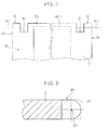
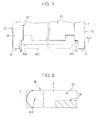
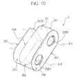
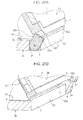
- the first hinge section 4 has a first hinge case 15 in which the thickness from one face 15A to the other face 15B is equal to the casing thickness and the distance from a side face 15C on one side to a side face 15D on the other side becomes the width of the above-mentioned first hinge section 4.
- one face 15A in the first hinge case 15 is also referred to as a first hinge one face 15A and the other face 158 in the first hinge case 15 is also referred to as a first hinge other face 15B.
- the thickness from the first hinge one face 15A to the first hinge other face 15B in the first hinge case 15 of the first hinge section 4 is also referred to as a first hinge thickness.
- a direction from the first hinge one face 15A toward the first hinge other face 15B in the first hinge section 4 and a direction from the first hinge other face 15B toward the first hinge one face 15A, which is opposite to the above direction, are also collectively referred to as a first hinge section thickness direction.
- the side face 15C on one side in the first hinge case 15 is also referred to as a first hinge left side face 15C and the side face 15D on the other side in the first hinge case 15 is also referred to as a first hinge right side face 15D.
- a direction from the first hinge left side face 15C toward the first hinge right side face 15D in the first hinge section 4 and a direction from the first hinge right side face 15D toward the first hinge left side face 15C, which is opposite to the above direction, are also collectively referred to as a first hinge section width direction.
- an end face 15E of one end is formed into an arc shape which follows a side face corresponding to the semicircle of a cylinder, the radius of which is a distance of 1/2 of the casing thickness, centering around a virtual line VL3 that is located in parallel with the first hinge section width direction at a distance of 1/2 of the casing thickness from the center of the end face 15E.
- an end face 15F of the other end is formed into an arc shape which follows a side face corresponding to the semicircle of a cylinder, the radius of which is a distance of 1/2 of the casing thickness, centering around a virtual line VL4 that is located in parallel with the first hinge section width direction at a distance of 1/2 of the casing thickness from the center of the end face 15F.
- first hinge case 15 one end of the first hinge case 15 is also referred to as a first hinge one end and the other end of the first hinge case 15 is also referred to as a first hinge other end.
- a direction from the top of the end face 15E of the first hinge one end in the first hinge section 4 toward the top of the end face 15F of the first hinge other end and a direction opposite to the direction are also collectively referred to as a first hinge section longitudinal direction.
- the length from the top of the arc-shaped end face 15E of the first hinge one end to the top of the arc-shaped end face 15F of the first hinge other end is selected so as to be approximately equal to a length of two times the casing thickness.
- the length from the top of the arc-shaped end face 15E of the first hinge one end in the first hinge case 15 to the top of the arc-shaped end face 15F of the first hinge other end is also referred to as a first hinge length.
- a cutout portion in which the depth thereof from the first hinge other end to the first hinge one end side is equal to 1/2 of the casing thickness is formed at the first hinge right side face 15D side in a first hinge other end portion.
- a portion on the first hinge right side face 15D side in the first hinge case 15 becomes a cam portion (hereinafter, this is also referred to as a first cam portion) 15G for displacing the holding section 8 in accordance with opening and closing of the first casing 2 and the second casing 3.
- the width of the first cam portion 15G (the width of the first cam end face 15GX) is selected so as to be equal to the width of the left cutout portion 8AX of the holding section 8.
- the width of the portion further on the left than the first portion 15G is selected so as to be approximately equal to the width of the portion actually cut out as the second casing left cutout portion 3F in the second casing one end portion of the second casing 3.
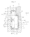
- a circular one end-side hole portion 15CX centering on the virtual line VL3 and having a given radius is perforated at the first hinge one end side.
- a circular other end-side hole portion 15CY centering on the virtual line VL4 and having the same radius as the one end-side hole portion 15CX is perforated at the first hinge other end side.
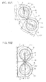
- the first hinge section 4 has two first and second cylindrical turning shafts 16 and 17 each having a radius approximately equal to that of the one end-side hole portion 15CX. Further, the first hinge section 4 also has two first and second disc-shaped pulleys 18 and 19 housed in the first hinge case 15.
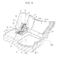
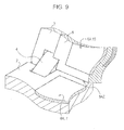
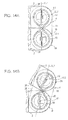
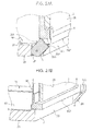
- Fig. 7 shows a state where the first casing 2 and the second casing 3 are opened at an angle of 180 degrees such that the first casing one face 2A and the second casing one face 3A line up (hereinafter, this is also referred to as a spread state). Further, Figs. 8 and 9 show a state where the first casing 2 and the second casing 3 are opened at an angle of about 120 degrees.
- the first turning shaft 16 is inserted into the one end-side hole portion 15CX of the first hinge case 15 so as to be able to turn around the virtual line VL3.
- one end protruding to the outside of the first hinge case 15 in the first turning shaft 16 is fixed to an inner wall of the first left shaft formation portion 2H of the first casing 2 in a state where the virtual line VL3 which becomes the center of turning of the first turning shaft 16 corresponds with the virtual line VL1.
- the other end entered into the first hinge case 15 in the first turning shaft 16 is fixed to a central portion of one face of the first pulley 18 in a state where the virtual line VL3 corresponds with the central axis of the first pulley 18.
- the second turning shaft 17 is inserted into the other end-side hole portion 15CY of the first hinge case 15 in parallel with the first turning shaft 16 so as to be able to turn around the virtual line VL4.
- One end protruding to the outside of the first hinge case 15 in the second turning shaft 17 is fixed to an inner wall of the second left shaft formation portion 3H of the second casing 3 in a state where the virtual line VL4 which becomes the center of turning of the second turning shaft 17 corresponds with the virtual line VL2.
- the other end entered into the first hinge case 15 in the second turning shaft 17 is fixed to a central portion of one face of the second pulley 19 in a state where the virtual line VL4 corresponds with the central axis of the second pulley 19.
- the first pulley 18 turns along with the first turning shaft 16 in the first hinge case 15 and the second pulley 19 also turns along with the second turning shaft 17.
- a wire 20 is wound in a figure of eight from a side face of the first pulley 18 to a side face of the second pulley 19. Then, one portion of the wire 20 is led and fixed to the other face of the first pulley 18 and the other portion is led and fixed to the other face of the second pulley 19.
- the wire 20 is wound around and fixed to the first pulley 18 and the second pulley 19, for example, in a state where the first casing 2 and the second casing 3 are opened at an angle of 180 degrees, whereby an end face of the first left shaft formation portion 2H and an end face of the second left shaft formation portion 3H come into contact with each other.
- the first pulley 18 and the second pulley 19 turn relative to each other in the opposite directions in synchronization with each other without sliding of the wire 20 on the side faces of the first and second pulleys 18 and 19.
- the first hinge section 4 connects the left side of the first casing one end portion of the first casing 2 and the left side of the second casing one end portion of the second casing 3, thereby allowing the first casing 2 and the second casing 3 to be opened and closed.
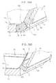
- the second hinge section 5 has a second hinge case 25 having a plane-symmetrical shape to the first hinge case 15 of the first hinge section 4. That is, in the second hinge case 25, the thickness from one face 25A to the other face 25B is selected so as to be equal to the casing thickness and the distance from a side face 25C on one side to a side face 25D on the other side becomes the width of the above-mentioned second hinge section 5.
- one face 25A in the second hinge case 25 is also referred to as a second hinge one face 25A and the other face 25B in the second hinge case 25 is also referred to as a second hinge other face 25B.
- the thickness from the second hinge one face 25A to the second hinge other face 25B in the second hinge case 25 of the second hinge section 5 is also referred to as a second hinge thickness.
- a direction from the second hinge one face 25A toward the second hinge other face 25B in the second hinge section 5 and a direction from the second hinge other face 25B toward the second hinge one face 25A, which is opposite to the above direction, are also collectively referred to as a second hinge section thickness direction.
- the side face 25C on one side in the second hinge case 25 is also referred to as a second hinge left side face 25C and the side face 25D on the other side in the second hinge case 25 is also referred to as a second hinge right side face 25D.
- a direction from the second hinge left side face 25C toward the second hinge right side face 25D in the second hinge section 5 and a direction from the second hinge right side face 25D toward the second hinge left side face 25C, which is opposite to the above direction, are also collectively referred to as a second hinge section width direction.
- an end face 25E of one end is formed into an arc shape which follows a side face corresponding to the semicircle of a cylinder, the radius of which is a distance of 1/2 of the casing thickness, centering around a virtual line VL5 that is located in parallel with the second hinge section width direction at a distance of 1/2 of the casing thickness from the center of the end face 25E.
- an end face 25F of the other end is formed into an arc shape which follows a side face corresponding to the semicircle of a cylinder, the radius of which is a distance of 1/2 of the casing thickness, centering around a virtual line VL6 that is located in parallel with the second hinge section width direction at a distance of 1/2 of the casing thickness from the center of the end face 25F.
- one end of the second hinge case 25 is also referred to as a second hinge one end and the other end of the second hinge case 25 is also referred to as a second hinge other end.
- a direction from the top of the end face 25E of the second hinge one end in the second hinge section 5 toward the top of the end face 25F of the second hinge other end and a direction opposite to the direction are also collectively referred to as a second hinge section longitudinal direction.
- the length from the top of the arc-shaped end face 25E of the second hinge one end to the top of the arc-shaped end face 25F of the second hinge other end is selected so as to be approximately equal to a length of two times the casing thickness.
- the length from the top of the arc-shaped end face 25E of the second hinge one end in the second hinge case 25 to the top of the arc-shaped end face 25F of the second hinge other end is also referred to as a second hinge length.
- a cutout portion in which the depth thereof from the second hinge other and to the second hinge one end side is equal to 1/2 of the casing thickness is formed at the second hinge left side face 25C side in a second hinge other end portion.
- the portion on the second hinge left side face 25C side in the second hinge case 25 becomes a cam portion (hereinafter, this is also referred to as a second cam portion) 25G for displacing the holding section 8 in accordance with opening and closing of the first casing 2 and the second casing 3.
- the width of the second cam portion 25G (the width of the second cam end face 25GX) is selected so as to be equal to width of the right cutout portion 8AY of the holding section 8.
- the width of the portion further on the right side than the second cam portion 25G is selected so as to be approximately equal to the width of a portion actually cut out as the second casing right cutout portion 3G in the second casing one end portion of the second casing 3.
- a circular one end-side hole portion 25DX centering on the virtual line VL5 and having the same radius as the above-mentioned one end-side hole portion 15CX is perforated at the second hinge one end side.
- a circular other end-side hole portion 25DY centering on the virtual line VL6 and having the same radius as the above-mentioned one end-side hole portion 15CX is perforated at the second hinge other end side.
- the second hinge section 5 has two first and second cylindrical turning shafts 26 and 27 each having a radius approximately equal to that of the above-mentioned one end-side hole portion 15CX. Further, the second hinge section 5 also has two first and second disc-shaped pulleys 28 and 29 housed in the second hinge case 25.
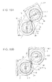
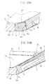
- Fig. 11 shows a spread state of the first casing 2 and the second casing 3
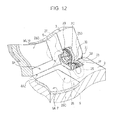
- Figs. 12 and 13 show a state where the first casing 2 and the second casing 3 are opened at an angle of about 120 degrees.
- the first turning shaft 26 is inserted into the one end-side hole portion 25DX of the second hinge case 25 so as to be able to turn around the virtual line VL5.
- one end protruding to the outside of the second hinge case 25 in the first turning shaft 26 is fixed to an inner wall of the first right shaft formation portion 2J of the first casing 2 in a state where the virtual line VL5 which becomes the center of turning of the first turning shaft 26 corresponds with the virtual line VL1.
- the other end entered into the second hinge case 25 in the first turning shaft 26 is fixed to a central portion of one face of the first pulley 28 in a state where the virtual line VL5 corresponds with the central axis of the first pulley 28.
- the second turning shaft 27 is inserted into the other end-side hole portion 25DY of the second hinge case 25 in parallel with the first turning shaft 26 so as to be able to turn around the virtual line VL6.
- One end protruding to the outside of the second hinge case 25 in the second turning shaft 27 is fixed to an inner wall of the second right shaft formation portion 3J of the second casing 3 in a state where the virtual line VL6 which becomes the center of turning of the second turning shaft 27 corresponds with the virtual line VL2.
- the other end entered into the second hinge case 25 in the second turning shaft 27 is fixed to a central portion of one face of the second pulley 29 in a state where the virtual line VL6 corresponds with the central axis of the second pulley 29.
- the first pulley 28 turns along with the first turning shaft 26 in the second hinge case 25 and the second pulley 29 also turns along with the second turning shaft 27.
- a wire 30 is wound in a figure of eight from a side face of the first pulley 28 to a side face of the second pulley 29. Further, one portion of the wire 30 is led and fixed to the other face of the first pulley 28 and the other portion is led and fixed to the other face of the second pulley 29.
- the wire 30 is wound around and fixed to the first pulley 28 and the second pulley 29, for example, in a state where the first casing 2 and the second casing 3 are opened at an angle of 180 degrees, whereby an end face of the first right shaft formation portion 2J and an end face of the second right shaft formation portion 3J come into contact with each other.
- the first pulley 28 and the second pulley 29 turn relative to each other in the opposite directions in synchronization with each other without sliding of the wire 30 on the side faces of the first and second pulleys 28 and 29.
- the second hinge section 5 connects the right side of the first casing one end portion of the first casing 2 and the right side of the second casing one end portion of the second casing 3, thereby allowing the first casing 2 and the second casing 3 to be opened and closed.
- each of the end face of the first left shaft formation portion 2H and the end face of the first right shaft formation portion 2J is formed into an arc shape so as to describe a semicircle, as described above.
- each of the end face of the second left shaft formation portion 3H and the end face of the second right shaft formation portion 3J is formed into an arc shape so as to describe a semicircle, as described above.
- the wire 20 is wound around and fixed to the first and second pulleys 18 and 19 in a state where the end face of the first left shaft formation portion 2H and the end face of the second left shaft formation portion 3H come into contact with each other.
- the wire 30 is wound around and fixed to the first and second pulleys 28 and 29 in a state where the end face of the first right shaft formation portion 2J and the end face of the second right shaft formation portion 3J come into contact with each other.
- the left and right sides of the first casing one end portion are formed plane-symmetrically and also in the second casing 3, the left and right sides of the second casing one end portion are formed plane-symmetrically. Further, the first hinge section 4 and the second hinge section 5 are also formed plane-symmetrically.
- the first hinge section 4 and the second hinge section 5 change positions in synchronization with each other in a state where the first left shaft formation portion 2H and the second left shaft formation portion 3H come into contact with each other and the first right shaft formation portion 2J and the second right shaft formation portion 3J also come into contact with each other.
- first hinge section 4 and the second hinge section 5 allow the first casing 2 and the second casing 3 to be freely opened or closed in a range from an angle of 0 degrees to an angle of 360 degrees.
- the first hinge section 4 and the second hinge section 5 allow the first casing 2 and the second casing 3 to be freely opened or closed without any catching of the first casing one end portion on the second casing one end portion.
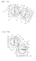
- the wire 20 which is wound over the first pulley 18 and the second pulley 19 intersects between the first pulley 18 and the second pulley 19 in a state where it is away from these pulleys.
- the first hinge section 4 displaces an intersection portion of the wires 20 between the first pulley 18 and the second pulley 19 without sliding of the wire 20 with respect to the first pulley 18 and the second pulley 19.
- the wire 30 which is wound over the first pulley 28 and the second pulley 29 intersects between the first pulley 28 and the second pulley 29 in a state where it is away from these pulleys.
- the second hinge section 5 displaces an intersection portion of the wires 30 between the first pulley 28 and the second pulley 29 without sliding of the wire 30 with respect to the first pulley 28 and the second pulley 29.
- the first hinge section 4 and the second hinge section 5 can relatively turn the first casing 2 and the second casing 3 in the opposite directions in synchronization with each other around the first turning shafts 16 and 26 and the second turning shafts 17 and 27.
- first hinge section 4 and the second hinge section 5 prevent occurrence of a step in a connection portion of the first casing 2 and the second casing 3 due to turning of either one only, thereby allowing the first casing 2 and the second casing 3 to be opened or closed as if they were connected to each other by one shaft.
- the first turning shaft 16 and the second turning shaft 17 respectively turn in the one end-side hole portion 15CX and the other end-side hole portion 15CY of the first hinge case 15.
- the first hinge length is selected so as to be approximately equal to a length of two times the casing thickness and also the first hinge thickness is selected so as to be approximately equal to the casing thickness.
- the first hinge section 4 changes a position in a state where the first hinge section longitudinal direction is in parallel with a virtual line VL7 orthogonal to the two virtual lines VL1 and VL2, in the first casing left cutout portion 2E and the second casing left cutout portion 3F.
- first turning shaft 26 and the second turning shaft 27 respectively turn in the one end-side hole portion 25DX and the other end-side hole portion 25DY of the second hinge case 25.
- the second hinge length is selected so as to be approximately equal to a length of two times the casing thickness and also the second hinge thickness is selected so as to be approximately equal to the casing thickness.
- the second hinge section 5 also changes a position in a state where the second hinge section longitudinal direction is in parallel with the virtual line VL7 orthogonal to the two virtual lines VL1 and VL2, in the first casing right cutout portion 2F and the second casing right cutout portion 3G.
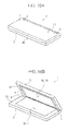
- first hinge section 4 and the second hinge section 5 avoid protrusion of the first casing one end portion and the second casing one end portion or the first casing other end portion and the second casing other end portion from the first casing other face 2B or the second casing other face 3B in the folded state ( Fig. 14A ) of the first casing 2 and the second casing 3.
- the first hinge section 4 and the second hinge section 5 avoid protrusion of the first casing one end portion and the second casing one end portion or the first casing other end portion and the second casing other end portion from the first casing one face 2A or the second casing one face 3A.
- the first hinge section 4 and the second hinge section 5 are integrated with the first casing 2 and the second casing 3 so as to form a single rectangular parallelepiped having a thickness of two times the casing thickness along with the first and second casings 2 and 3 which are superposed.
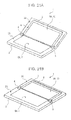
- first hinge section 4 and the second hinge section 5 avoid protrusion of the first hinge one face 15A and the second hinge one face 25A from the first casing one face 2A and the second casing one face 3A in the spread state ( Fig. 16B ) of the first casing 2 and the second casing 3.
- first hinge section 4 and the second hinge section 5 also avoid protrusion of the first hinge other face 15B and the second hinge other face 25B from the first casing other face 2B and the second casing other face 3B in the spread state ( Fig. 16B ) of the first casing 2 and the second casing 3.
- the first hinge section 4 and the second hinge section 5 are integrated with the first casing 2 and the second casing 3 so as to form a single rectangular parallelepiped having the casing thickness along with the first and second casings 2 and 3 which are lined up.
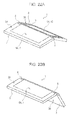
- the first casing 2 and the second casing 3 can be freely opened and closed in a range from 0 degrees (the folded state shown in Fig. 19A ) to 360 degrees (the back-to-back state shown in Fig. 23B ).
- one or a plurality of springs (a coil spring, a leaf spring, or the like) is provided at the second casing other end side in the cutout portion for displacement 3E.
- the second display section 9 is biased along with the holding section 8 to the second casing one end side by the spring in the cutout portion for displacement 3E.
- the first hinge section 4 makes the portion near the first hinge right side face 15D of the first hinge one face 15A strike the bottom face of the left cutout portion 8AX of the holding section 8.
- the second hinge section 5 makes the portion near the second hinge left side face 25C of the second hinge one face 25A strike the bottom face of the right cutout portion 8AY of the holding section 8.
- first hinge section 4 and the second hinge section 5 align the positions of the bottom faces of the left cutout portion 8AX and the right cutout portion 8AY with the positions of the bottom of the second casing left cutout portion 3F and the second right cutout portion 3G of the second casing 3 and displace the second display section 9 along with the holding section 8 to the second casing other end side.
- the depth from the holding section one end face 8AZ to the bottom face of each of the left cutout portion 8AX and the right cutout portion 8AY is selected so as to be about 1/2 of the casing thickness.
- the depth from the first casing one end face 2G of the first casing one end central portion to the bottom face of each of the first casing left cutout portion 2E and the first casing right cutout portion 2F is selected so as to be approximately equal to the casing thickness.
- the first hinge thickness and the second hinge thickness are selected so as to be approximately equal to the casing thickness.
- the first hinge longitudinal direction is made to be in parallel with the first casing thickness direction (and the second casing thickness direction), whereby the first hinge section 4 is located over an area from the inside of the first casing left cutout portion 2E of the first casing 2 to the inside of the second casing left cutout portion 3F of the second casing 3.
- the first hinge section 4 makes the portion (that is, the portion near the first hinge right side face 15D from the center to an edge of the first cam end face 15GX) of the first cam portion 15G in the first hinge one face 15A strike the bottom face of the left cutout portion 8AX of the holding section 8.
- the second hinge longitudinal direction is made to be in parallel with the first casing thickness direction (and the second casing thickness direction), whereby the second hinge section 5 is located over an area from the inside of the first casing right cutout portion 2F of the first casing 2 to the inside of the second casing right cutout portion 3G of the second casing 3.
- first hinge section 4 and the second hinge section 5 displace the second display section 9 along with the holding section 8 to the second casing other end side in the cutout portion for displacement 3E so as to make the holding section one end face 8AZ of the holding section 8 be located at the second casing other end side by a distance of 1/2 of the casing thickness.
- the first hinge section 4 and the second hinge section 5 make the first casing one end face 2G and the holding section one end face 8AZ be located away from each other.
- first hinge section 4 and the second hinge section 5 allow the first casing 2 and the second casing 3 to be opened from the folded state without any catching of an edge of the first casing one end face 2G on an edge of the holding section one end face 8AZ.
- the first hinge section 4 changes a position such that the first hinge section longitudinal direction gradually tilts with respect to the first casing thickness direction.
- the first hinge section 4 makes the portion (the central portion near the first hinge right side face 15D) of the first cam portion 15G in the first hinge one face 15A be gradually separated from the bottom face of the left cutout portion 8AX of the holding section 8, thereby making an edge of the first cam end face 15GX strike the bottom face of the left cutout portion 8AX.
- the first hinge section 4 changes the contact position of an edge of the first cam end face 15GX with respect to the bottom face of the left cutout portion 8AX of the holding section 8 from the center of the bottom face to the second casing one face 3A side while changing a position in accordance with an increase in an open angle of the first casing 2 and the second casing 3.
- the second hinge section 5 changes a position such that the second hinge section longitudinal direction gradually tilts with respect to the first casing thickness direction. Accordingly, the second hinge section 5 makes the portion (the central portion near the second hinge left side face 25C) of the second cam portion 25G in the second hinge one face 25A be gradually separated from the bottom face of the right cutout portion 8AY of the holding section 8, thereby making an edge of the second cam end face 25GX strike the bottom face of the right cutout portion 8AY.
- the second hinge section 5 changes the contact position of an edge of the second cam end face 25GX with respect to the bottom face of the right cutout portion 8AY of the holding section 8 from the center of the bottom face to the second casing one face 3A side while changing a position in accordance with an increase in an open angle of the first casing 2 and the second casing 3.
- the first hinge section 4 and the second hinge section 5 make the holding section one end face 8AZ of the holding section 8 be in a state where it is slightly away from a position near the first casing one end of the first casing one face 2A.
- the first hinge section 4 and the second hinge section 5 make the holding section one end face 8AZ strike a corner portion between the first casing one face 2A and the first casing one end face 2G.
- the holding section 8 is in a state where it is slightly away from the first cam end face 15GX and the second cam end face 25GX.
- the holding section 8 is further displaced along with the second display section 9 to the second casing one end side while changing the contact position of the holding section one end face 8AZ with respect to an edge near the first casing one end of the first casing one face 2A to the second casing one face 3A side.
- the first hinge section 4 changes a position such that the first hinge section longitudinal direction is in parallel with the first casing depth direction and the second casing depth direction.
- the first hinge section 4 is located over an area from the inside of the first casing left cutout portion 2E of the first casing 2 to the inside of the second casing left cutout portion 3F of the second casing 3, thereby making the first cam end face 15GX strike the bottom face of the left cutout portion 8AX of the holding section 8.
- the second hinge section 5 changes a position such that the second hinge section longitudinal direction is in parallel with the first casing depth direction and the second casing depth direction.
- the second hinge section 5 is located over an area from the inside of the first casing right cutout portion 2F of the first casing 2 to the inside of the second casing right cutout portion 3G of the second casing 3, thereby making the second cam end face 25GX strike the bottom face of the right cutout portion 8AY of the holding section 8.
- first hinge section 4 and the second hinge section 5 displace the second display section 9 along with the holding section 8 to the second casing other end side to the fullest extent in the cutout portion for displacement 3E, thereby making the holding section one end face 8AZ of the holding section 8 strike the first casing one end face 2G of the first casing one end central portion.
- first hinge section 4 and the second hinge section 5 bring the second display surface 9A close to the first display surface 6A.
- the first hinge section 4 and the second hinge section 5 can arrange the first display surface 6A of the first display section 6 and the second display surface 9A of the second display section 9 as if they were a single display surface.
- the holding section 8 makes the planar holding section one end face 8AZ strike the planar first casing one end face 2G of the first casing 2 in a state where the holding section 8 is biased to the second casing one end side.
- first hinge section 4 and the second hinge section 5 make the planar first cam end face 15GX strike the planar bottom face of the left cutout portion 8AX of the holding section 8 and also make the planar second cam end face 25GX strike the planar bottom face of the right cutout portion 8AY of the holding section 8, as described above.
- first hinge section 4 and the second hinge section 5 lock (fix) the first casing 2 and the second casing 3 in the spread state. Accordingly, the first hinge section 4 and the second hinge section 5 can keep the spread state such that the open angle of the first casing 2 and the second casing 3 does not easily change even if the first casing 2 and the second casing 3 are lifted up, for example, in the spread state.
- the holding section one end face 8AZ is placed on a corner portion between the first casing other face 2B and the first casing one end face 2G, so that the holding section 8 enters a state where it is away from the first cam end face 15GX and the second cam end face 25GX.
- the holding section 8 is displaced again along with the second display section 9 to the second casing other end side in the cutout portion for displacement 3E while changing the contact position of the holding section one end face 8AZ with respect to the corner portion between the first casing other face 2B and the first casing one end face 2G to the second casing one face 3A side.
- first hinge section 4 and the second hinge section 5 change positions such that the first hinge section longitudinal direction and the second hinge section longitudinal direction gradually tilt with respect to the first casing depth direction, thereby being brought close to the first casing thickness direction.
- the first hinge section 4 makes an edge of the first cam end face 15GX in the first hinge other face 15B strike a portion near the second casing other face 3B in the bottom face of the left cutout portion 8AX of the holding section 8.
- the first hinge section 4 changes a position in accordance with an increase in an open angle of the first casing 2 and the second casing 3. Accordingly, the first hinge section 4 changes the contact position of an edge of the first cam end face 15GX with respect to the bottom face of the left cutout portion 8AX of the holding section 8 from the second casing other face 3B side in the bottom face of the left cutout portion 8AX to the center side.
- the second hinge section 5 makes an edge of the second cam end face 25GX in the second hinge other face 25B strike a portion near the second casing other face 3B in the bottom face of the right cutout portion 8AY of the holding section 8.
- the second hinge section 5 also changes a position in accordance with an increase in an open angle of the first casing 2 and the second casing 3. Accordingly, the second hinge section 5 changes the contact position of an edge of the second cam end face 25GX with respect to the bottom face of the right cutout portion 8AY of the holding section 8 from the second casing other face 3B side in the bottom face of the right cutout portion 8AY to the center side.
- the first hinge section 4 and the second hinge section 5 make the holding section one end face 8AZ of the holding section 8 be in a state where it is slightly away from a position near the first casing one end of the first casing other face 2B.
- the first hinge section 4 further changes a position in accordance with an increase in an open angle of the first casing 2 and the second casing 3, the first hinge section 4 further changes the contact position of an edge of the first cam end face 15GX with respect to the bottom face of the left cutout portion 8AX of the holding section 8 to the center side of the bottom face.
- the second hinge section 5 further changes the contact position of an edge of the second cam end face 25GX with respect to the bottom face of the right cutout portion 8AY of the holding section 8 to the center side of the bottom face while further changing a position in accordance with an increase in an open angle of the first casing 2 and the second casing 3.
- the first hinge section 4 gradually brings the portion (that is, the central portion near the first hinge right side face 15D) of the first cam portion 15G in the first hinge other face 15B close to the bottom face of the left cutout portion 8AX of the holding section 8 in accordance with an increase in an open angle of the first casing 2 and the second casing 3.
- the second hinge section 5 gradually brings the portion (that is, the central portion near the second hinge left side face 25C) of the second cam portion 25G in the second hinge other face 25B close to the bottom face of the right cutout portion 8AY of the holding section 8 in accordance with an increase in an open angle of the first casing 2 and the second casing 3.
- the first hinge section 4 makes the first hinge section longitudinal direction be in parallel with the first casing thickness direction (and the second casing thickness direction), thereby being located over an area from the inside of the first casing left cutout portion 2E of the first casing 2 to the inside of the second casing left cutout portion 3F of the second casing 3.
- the first hinge section 4 makes the portion (that is, the portion from the center near the first hinge right side face 15D to an edge of the first cam end face 15GX) of the first cam portion 15G in the first hinge other face 15B strike the bottom face of the left cutout portion 8AX of the holding section 8.
- the second hinge section 5 makes the second hinge section longitudinal direction be in parallel with the first casing thickness direction (and the second casing thickness direction), thereby being located over an area from the inside of the first casing right cutout portion 2F of the first casing 2 to the inside of the second casing right cutout portion 3G of the second casing 3.
- the second hinge section 5 makes the portion (that is, the portion from the center near the second hinge left side face 25C to an edge of the second cam end face 25GX) of the second cam portion 25G in the second hinge other face 25B strike the bottom face of the right cutout portion 8AY of the holding section 8.
- first hinge section 4 and the second hinge section 5 displace the second display section 9 along with the holding section 8 to the second casing other face side in the cutout portion for displacement 3E so as to make the holding section one end face 8AZ of the holding section 8 be located at the second casing other end side by a distance of 1/2 of the casing thickness.
- the first hinge section 4 and the second hinge section 5 make the first casing one end face 2G of a planar shape and the holding section one end face 8AZ of a planar shape be located away from each other.
- first hinge section 4 and the second hinge section 5 can make the first casing 2 and the second casing 3 be closed from the back-to-back state without any catching of an edge of the first casing one end face 2G on an edge of the holding section one end face 8AZ.
- the first hinge section 4 and the second hinge section 5 displace the holding section 8 along with the second display section 9 while changing positions in a reverse procedure to the above procedure and can finally return to the folded state.
- the first casing 2 and the second casing 3 are connected to each other through the first and second hinge sections 4 and 5 having the first turning shafts 16 and 26 provided at the first casing one end portion and the second turning shafts 17 and 27 provided at the second casing one end portion, so as to be able to be opened and closed.
- the second display section 9 provided on the second casing one face 3A of the second casing 3 is displaced to the second casing other end side, and in the spread state of the first casing 2 and the second casing 3, the second display section 9 is displaced to the second casing one end side.
- the amount of eye movement between the first display surface 6A and the second display surface 9A can be reduced.
- the electronic apparatus 1 is made such that the first casing 2 and the second casing 3 are connected to each other through the first and second hinge sections 4 and 5 having the first turning shafts 16 and 26 provided at the first casing one end portion and the second turning shafts 17 and 27 provided at the second casing one end portion, so as to be able to be opened and closed in a range from the folded state to the back-to-back state, and such that in the folded state and the back-to-back state of the first casing 2 and the second casing 3, the second display section 9 provided on the second casing one face 3A is displaced to the second casing other end side and in the spread state of the first casing 2 and the second casing 3, the second display section 9 is displaced to the second casing one end side.
- the electronic apparatus 1 in a situation where the first display surface 6A in the first casing one face 2A and the second display surface 9A in the second casing one face 3A are visually observed in the spread state of the first casing 2 and the second casing 3, the amount of eye movement between the first display surface 6A and the second display surface 9A can be reduced, so that eyestrain can be reduced. Therefore, in the electronic apparatus 1, usability can be improved.
- first hinge section 4 and the second hinge section 5 are provided close to the first and second casing left side faces 2C and 3C and the first and second casing right side faces 2D and 3D in the first casing one end portion of the first casing 2 and the second casing one end portion of the second casing 3.
- the second display section 9 is provided at the central portion of the second casing one face 3A of the second casing 3.
- the thicknesses of the first and second casings 2 and 3 and the thicknesses of the first and second hinge sections 4 and 5 are selected so as to be the same. Then, in the electronic apparatus 1, the first hinge section 4 and the second hinge section 5 are provided with respect to the first casing 2 and the second casing 3 such that the first hinge section 4 and the second hinge section 5 do not protrude from the first and second casing one faces 2A and 3A and the first and second casing other faces 2B and 3B in the spread state.
- the first and second casings 2 and 3 as a whole can be made to be a single plate-like casing.
- the first display surface 6A and the second display surface 9A can be disposed and used at the central portion of one large display surface made of the first casing one face 2A and the second casing one face 3A in the first casing 2 and the second casing 3 as if they were one large display surface.
- the first turning shafts 16 and 26 and the second turning shafts 17 and 27 are made to be housed along with the first pulleys 18 and 28, the second pulleys 19 and 29, and the like in the first hinge case 15 and the second hinge case 25.
- the electronic apparatus 1 in the first hinge section 4 and the second hinge section 5, it is possible to protect the first turning shafts 16 and 26, the second turning shafts 17 and 27, the first pulleys 18 and 28, the second pulleys 19 and 29, and the like from dust or the like, thereby allowing them to function in an optimal state at all times.
- the second display section 9 provided on the second casing one face 3A of the second casing 3 is made so as to be biased to the second casing one end side by the spring.
- the first cam portion 15G and the second cam portion 25G are made so as to be provided at the first hinge case 15 and the second hinge case 25 of the first hinge section 4 and the second hinge section 5.
- the second display section 9 is displaced to the second casing other end side and also to the second casing one end side by the first cam portion 15G and the second cam portion 25G.
- the second display section 9 is displaced to the second casing other end side.
- the second display section 9 when closing the first casing 2 and the second casing 3 from the spread state, the second display section 9 is displaced along with the holding section 8 to the second casing other end side by using the corner portion between the first casing one face 2A and the first casing one end face 2G without using the first cam portion 15G and the second cam portion 25G.
- the electronic apparatus 1 when starting to further open the first casing 2 and the second casing 3 from the spread state in order to make them back-to-back, by making the holding section one end face 8AZ of the holding section 8 be placed on a corner portion between the first casing other face 2B and the first casing one end face 2G, the second display section 9 is displaced to the second casing other end side.
- the second display section 9 is displaced along with the holding section 8 to the second casing other end side by using the corner portion between the first casing other face 2B and the first casing one end face 2G without using the first cam portion 15G and the second cam portion 25G.
- the electronic apparatus 1 it is possible to easily and reliably displace the second display section 9 to the second casing one end side and the second casing other end side in accordance with opening and closing of the first casing 2 and the second casing 3,
- the wires 20 and 30 are respectively wound in a figure of eight on the first pulleys 18 and 28 and the second pulleys 19 and 29 fixed to one ends of the first turning shafts 16 and 26 and one ends of the second turning shafts 17 and 27 in the first hinge section 4 and the second hinge section 5.
- the first hinge section 4 and the second hinge section 5 can be reduced in size as much as possible.
- the electronic apparatus 1 is reduced in size as a whole, thereby being capable of being easily carried. Then, at this time, in the electronic apparatus 1, it is possible to hide and protect the first display surface 6A and the second display surface 9A from the outside and also prevent erroneous operations of the first touch panel 7 and the second touch panel 10.
- the first display surface 6A and the second display surface 9A are flush with each other and brought close to each other, thereby being made as if they were one large display surface, and it is then possible to display one or a plurality of images thereon. Further, at this time, in the electronic apparatus 1, it is possible to perform a touch operation on a display surface made as if it were one large display surface.
- the electronic apparatus 1 is reduced in size as a whole, thereby being capable of being easily carried. Then, in the electronic apparatus 1, at this time, for example, even during carrying, it is possible to expose the first display surface 6A and the second display surface 9A and then display various images and it is also possible to perform a touch operation on the first display surface 6A and the second display surface 9A.
- first and second cam end faces 15GX and 25GX of the first and second hinge sections 4 and 5 and the bottom faces of the left and right cutout portions 8AX and 8AY of the holding section 8 have a planar form.
- each of a first cam end face 40A of a first hinge section 40 and a second cam end face 41A of a second hinge section 41 may be formed into a convex shape, as shown in Figs. 31A and 31B .
- each of the bottom faces of a left cutout portion 42A and a right cutout portion 42B of a holding section 42 may be formed into a concave shape being matched with the shape of each of the first cam end face 40A and the second cam end face 41A.
- the present disclosure is not limited thereto and the first casing 2 may be made to function as a keyboard by arranging a plurality of operation keys on the first casing one face 2A of the first casing 2.
- first casing 2 and the second casing 3 may be connected to each other through a single hinge section so as to be able to be opened and closed.
- the hinge section may be provided close to one side of the first and second casing left side faces 2C and 3C and the first and second right side faces 2D and 3D of the first and second casing one end portions.
- the first casing left cutout portion 2E is formed close to the first casing left side face 2C in the first casing one end portion and also the first casing right cutout portion 2F is formed close to the first casing right side face 2D.
- the present disclosure is not limited thereto and for disposition of the first hinge section 4 and the second hinge section 5, in the first casing, the left cutout portion is formed in the first casing one end portion of the first casing left side face and also the right cutout portion is formed in the first casing one end portion of the first casing right side face.
- the left cutout portion is formed in the second casing one end portion of the second casing left side face and also the right cutout portion is formed in the second casing one end portion of the second casing right side face.
- the first turning shaft is provided in parallel with the first casing width direction at an inner wall of the left cutout portion of the first casing left side face and also the second turning shaft is provided in parallel with the first casing width direction at an inner wall of the right cutout portion of the first casing right side face.
- the first turning shaft is provided in parallel with the second casing width direction at an inner wall of the left cutout portion of the second casing left side face and also the second turning shaft is provided in parallel with the second casing width direction at an inner wall of the right cutout portion of the second casing right side face.
- the first hinge section having the first turning shaft and the second turning shaft is disposed over the left cutout portion of the first casing left side face and the left cutout portion of the second casing left side face.
- the second hinge section having the first turning shaft and the second turning shaft is disposed over the right cutout portion of the first casing right side face and the right cutout portion of the second casing right side face.
- the first casing and the second casing may be connected to each other through the first hinge section and the second hinge section so as to be able to be opened and closed.
- a first cam portion and a second cam portion can also be provided at the first hinge section and the second hinge section, similarly to the above description. Then, in the present disclosure, in the case of such a configuration, by narrowing the widths of the first casing and the second casing or widening the width of the holding section compared to the above-described embodiments, it is possible to displace the second display section along with the holding section by using the first cam portion and the second cam portion.
- the present disclosure is not limited thereto and the electronic apparatus can be applied to a folding-type PDA (Personal Digital Assistance), a folding-type personal computer (that is, a notebook computer), a folding-type mobile telephone, or a folding-type portable game machine.
- a folding-type PDA Personal Digital Assistance
- a folding-type personal computer that is, a notebook computer
- a folding-type mobile telephone or a folding-type portable game machine.
- the present disclosure can be widely applied to folding-type electronic apparatuses having various other configurations, like an electronic apparatus which is formed by pivotally connecting a first casing provided with a display section or an operation section and a second casing provided with a display section through a hinge section.
- first casings having various other configurations, like a first casing in which each of one face and the other face is formed into a racetrack shape, an elliptical shape, or a trapezoidal shape, a first casing having a different thickness from that of a second casing, or the like.
- second casings having various other configurations, like a second casing in which each of one face and the other face is formed into a racetrack shape, an elliptical shape, or a trapezoidal shape, a second casing having a different thickness from that of a first casing, or the like.
- hinge sections each of which has a first turning shaft provided at the first casing one end portion of the first casing and a second turning shaft provided at the second casing one end portion of the second casing and connects the first casing and the second casing so as to be able to be opened and closed in a range from the folded state to the back-to-back state through the first turning shaft and the second turning shaft, the first hinge section 4 and the second hinge section 5 described above with reference to Figs. 1 to 31B are applied.
- the present disclosure is not limited thereto and a hinge section provided only at the side face side of one of the first casing 2 and the second casing 3 or hinge sections which have no hinge case and expose the first turning shafts 16 and 26 and the second turning shafts 17 and 27 along with the first pulleys 18 and 28 and the second pulleys 19 and 29 may be applied.
- hinge sections having various other configurations, like a hinge section which has at least two gears respectively fixed to one end of a first turning shaft and one end of a second turning shaft and turns the first and second turning shafts in the opposite directions by making at least two gears be directly engaged with each other or be engaged with each other through an even number of gears, or the like.
- the present disclosure is not limited thereto and it is possible to widely apply display sections having various other configurations, like a display panel integrated with a touch panel, a sheet-like display section, or the like.
- displacement sections having various other configurations, such as a displacement section which is constituted by a spring biasing the second display section 9 provided at the second casing 2 to the second casing one end side and a wire connecting one side of the first pulleys 18 and 28 and the second pulleys 19 and 29 to an end portion on the second casing other end side in the second display section 9, or the like.
- the second display section 9 in the spread state of the first casing 2 and the second casing 3, the second display section 9 is biased and displaced to the second casing one end side by the spring by bending the wire.
- the second display section 9 is displaced to the second casing other end side by winding the wire by a given amount by one side of the first pulleys 18 and 28 and the second pulleys 19 and 29.
- hinge cases having various other configurations, like a hinge case formed exclusively of a cam portion, or the like.
- the present invention is not limited thereto and it is possible to widely apply display sections having various other configurations, like a display panel integrated with a touch panel, a sheet-like display section, or the like.
- an electronic apparatus comprising: a first casing; a second casing; a hinge section which includes a first turning shaft provided at a first casing one end portion of the first casing and a second turning shaft provided at a second casing one end portion of the second casing and connects the first casing and the second casing so as to be able to be opened or closed in a range from a folded state to a back-to-back state through the first turning shaft and the second turning shaft; a display section provided on a second casing one face of the second casing; and a displacement section which displaces the display section to the second casing other end side of the second casing in the folded state and the back-to-back state of the first casing and the second casing and displaces the display section to the second casing one end side in a spread state of the first casing and the second casing.
- the hinge section includes the first turning shaft provided close to a first casing side face in the first casing one end portion of the first casing, and the second turning shaft provided close to a second casing side face in the second casing one end portion of the second casing, and the display section is provided at a central portion of the second casing one face of the second casing.
- first casing and the second casing have the same thickness
- the hinge section has the same thickness as the thicknesses of the first casing and the second casing, changes a position in accordance with opening and closing of the first casing and the second casing, and is provided so as not to protrude from the first casing one face, the second casing one face, the first casing other face, and the second casing other face in the spread state of the first casing and the second casing.
- the hinge section includes a hinge case which has the same thickness as the thicknesses of the first casing and the second casing and houses the first turning shaft and the second turning shaft.
- the apparatus further comprises a spring which biases the display section to the second casing one end side, and wherein the displacement section includes a cam portion provided at the hinge case of the hinge section so as to displace the display section biased to the second casing one end side by the spring, in accordance with opening and closing of the first casing and the second casing.
- the hinge section includes a first pulley housed in the hinge case and fixed to the first turning shaft, a second pulley housed in the hinge case and fixed to the second turning shaft, and a wire housed in the hinge case and wound in a figure of eight from a side face of the first pulley to a side face of the second pulley.
- the apparatus further comprises a display section provided at a central portion of the first casing one face of the first casing.
Landscapes
- Engineering & Computer Science (AREA)
- Computer Hardware Design (AREA)
- Theoretical Computer Science (AREA)
- Human Computer Interaction (AREA)
- Physics & Mathematics (AREA)
- General Engineering & Computer Science (AREA)
- General Physics & Mathematics (AREA)
- Microelectronics & Electronic Packaging (AREA)
- Telephone Set Structure (AREA)
- Casings For Electric Apparatus (AREA)
- Pivots And Pivotal Connections (AREA)
Applications Claiming Priority (1)
| Application Number | Priority Date | Filing Date | Title |
|---|---|---|---|
| JP2010199346A JP2012057662A (ja) | 2010-09-06 | 2010-09-06 | 電子機器 |
Publications (1)
| Publication Number | Publication Date |
|---|---|
| EP2426573A2 true EP2426573A2 (en) | 2012-03-07 |
Family
ID=44674350
Family Applications (1)
| Application Number | Title | Priority Date | Filing Date |
|---|---|---|---|
| EP11179292A Withdrawn EP2426573A2 (en) | 2010-09-06 | 2011-08-30 | Electronic apparatus |
Country Status (5)
| Country | Link |
|---|---|
| US (2) | US8638546B2 (enExample) |
| EP (1) | EP2426573A2 (enExample) |
| JP (1) | JP2012057662A (enExample) |
| CN (2) | CN102387684A (enExample) |
| TW (1) | TW201232230A (enExample) |
Cited By (1)
| Publication number | Priority date | Publication date | Assignee | Title |
|---|---|---|---|---|
| EP3467614A4 (en) * | 2016-06-24 | 2019-07-03 | Samsung Electronics Co., Ltd. | ELECTRONIC DEVICE WITH SEVERAL VIEWS |
Families Citing this family (54)
| Publication number | Priority date | Publication date | Assignee | Title |
|---|---|---|---|---|
| TWI395879B (zh) * | 2009-11-03 | 2013-05-11 | Pegatron Corp | 電子裝置 |
| USD717304S1 (en) * | 2012-03-26 | 2014-11-11 | Patientsafe Solutions, Inc. | Scanning jacket for a handheld device |
| US8687351B2 (en) | 2011-03-31 | 2014-04-01 | Patientsafe Solutions, Inc. | Scanning jacket for a handheld device |
| US8787016B2 (en) * | 2011-07-06 | 2014-07-22 | Apple Inc. | Flexible display devices |
| US20130076654A1 (en) * | 2011-09-27 | 2013-03-28 | Imerj LLC | Handset states and state diagrams: open, closed transitional and easel |
| US9891729B2 (en) | 2012-07-10 | 2018-02-13 | Sony Corporation | Operation processing device and method for user interface |
| US8971031B2 (en) | 2012-08-07 | 2015-03-03 | Creator Technology B.V. | Display system with a flexible display |
| CN104620188A (zh) | 2012-09-12 | 2015-05-13 | 惠普发展公司,有限责任合伙企业 | 用于计算机壳体的闭锁部 |
| KR101986762B1 (ko) * | 2012-10-19 | 2019-06-10 | 삼성디스플레이 주식회사 | 접이식 표시 장치 |
| TWI515373B (zh) * | 2013-02-08 | 2016-01-01 | First Dome Corp | Synchronization device of double shaft and its combination method |
| TWM461973U (zh) * | 2013-02-08 | 2013-09-11 | First Dome Corp | 轉軸傳動結構 |
| TWM458068U (zh) * | 2013-02-08 | 2013-07-21 | First Dome Corp | 雙轉軸之同步運動裝置 |
| US9477261B1 (en) * | 2013-02-14 | 2016-10-25 | Google Inc. | Portable computer with cylinders providing friction in hinge |
| TWM466285U (zh) * | 2013-03-27 | 2013-11-21 | First Dome Corp | 雙軸式轉軸樞轉定位結構 |
| CN104100629B (zh) * | 2013-04-15 | 2016-09-28 | 富世达股份有限公司 | 用于双转轴的同步运动装置 |
| KR20240014622A (ko) * | 2013-04-24 | 2024-02-01 | 가부시키가이샤 한도오따이 에네루기 켄큐쇼 | 표시 장치 |
| JP2015129917A (ja) * | 2013-12-02 | 2015-07-16 | 株式会社半導体エネルギー研究所 | 情報処理装置 |
| JP6081960B2 (ja) * | 2014-06-09 | 2017-02-15 | レノボ・シンガポール・プライベート・リミテッド | 携帯型情報処理装置、その通話方法、及びコンピュータが実行可能なプログラム |
| USD719167S1 (en) * | 2014-08-22 | 2014-12-09 | Patientsafe Solutions, Inc. | Scanning jacket for a handheld personal digital assistant (PDA) device |
| USD719166S1 (en) * | 2014-08-22 | 2014-12-09 | Patientsafe Solutions, Inc. | Scanning jacket for a handheld phone device |
| KR102281845B1 (ko) * | 2014-11-11 | 2021-07-26 | 삼성디스플레이 주식회사 | 표시 패널의 지지 장치 |
| KR102313066B1 (ko) * | 2014-11-17 | 2021-10-15 | 삼성디스플레이 주식회사 | 휴대용 표시 장치 |
| KR102333557B1 (ko) * | 2014-12-30 | 2021-12-01 | 엘지디스플레이 주식회사 | 접이식 디스플레이 장치 |
| KR102322377B1 (ko) | 2014-12-31 | 2021-11-05 | 엘지디스플레이 주식회사 | 접이식 디스플레이 장치 |
| EP3851161A1 (en) | 2015-10-15 | 2021-07-21 | DUSA Pharmaceuticals, Inc. | Adjustable illuminator for photodynamic therapy and diagnosis |
| US10227808B2 (en) | 2015-11-20 | 2019-03-12 | Microsoft Technology Licensing, Llc | Hinged device |
| US9740240B1 (en) | 2016-03-21 | 2017-08-22 | Google Inc. | Base with rotating mount that increases friction of rotation when portable computing device is placed onto mount |
| JP6797393B2 (ja) * | 2016-06-02 | 2020-12-09 | 株式会社ナチュラレーザ・ワン | 2軸ヒンジ並びにこの2軸ヒンジを用いた端末機器 |
| US10474203B2 (en) | 2016-09-01 | 2019-11-12 | Microsoft Technology Licensing, Llc | Hinged device |
| US10364598B2 (en) | 2016-09-02 | 2019-07-30 | Microsoft Technology Licensing, Llc | Hinged device |
| KR102605289B1 (ko) | 2016-09-05 | 2023-11-24 | 엘지전자 주식회사 | 디스플레이 장치 |
| US10241548B2 (en) | 2016-12-09 | 2019-03-26 | Microsoft Technology Licensing, Llc | Computing device employing a self-spacing hinge assembly |
| US10641318B2 (en) | 2016-12-09 | 2020-05-05 | Microsoft Technology Licensing, Llc | Hinged device |
| TWI633413B (zh) * | 2016-12-15 | 2018-08-21 | 宏碁股份有限公司 | 可攜式電子裝置 |
| US10253804B2 (en) | 2017-01-24 | 2019-04-09 | Microsoft Technology Licensing, Llc | Hinged device |
| US10732677B2 (en) | 2017-04-26 | 2020-08-04 | Intel Corporation | Close clearance hinge systems |
| US10296044B2 (en) | 2017-06-08 | 2019-05-21 | Microsoft Technology Licensing, Llc | Hinged device |
| US10344510B2 (en) | 2017-06-16 | 2019-07-09 | Microsoft Technology Licensing, Llc | Hinged device |
| US10357567B1 (en) | 2018-01-12 | 2019-07-23 | Dusa Pharmaceuticals, Inc. | Methods for photodynamic therapy |
| JP7170164B2 (ja) * | 2018-02-05 | 2022-11-14 | パナソニックIpマネジメント株式会社 | レンジフード |
| US10732679B2 (en) * | 2018-11-30 | 2020-08-04 | Dell Products L.P. | Portable information handling system low height mono barrel hinge |
| KR102661194B1 (ko) * | 2019-02-15 | 2024-04-29 | 삼성전자 주식회사 | 하우징, 하우징 제조 방법 및 그것을 포함하는 전자 장치 |
| CN109830903B (zh) * | 2019-03-29 | 2020-05-22 | 上海交通大学 | 一种全折叠式配电箱 |
| CN109992054B (zh) * | 2019-03-30 | 2021-04-13 | 联想(北京)有限公司 | 一种电子设备、连接装置 |
| CN112228446A (zh) * | 2019-07-15 | 2021-01-15 | 深圳市柔宇科技有限公司 | 折叠装置及电子设备 |
| WO2021078366A1 (en) | 2019-10-22 | 2021-04-29 | Huawei Technologies Co., Ltd. | Hinge assembly for controlled folding of an electronic device |
| US11009921B1 (en) * | 2020-05-14 | 2021-05-18 | Apple Inc. | Electronic devices with adjustable hinges |
| KR102810781B1 (ko) * | 2020-07-22 | 2025-05-21 | 삼성전자 주식회사 | 전자 장치용 커버 |
| US11720151B2 (en) | 2020-08-03 | 2023-08-08 | Microsoft Technology Licensing, Llc | Hinged device |
| US11669132B2 (en) * | 2020-09-29 | 2023-06-06 | Microsoft Technology Licensing, Llc | Hinge assembly for mobile computing device |
| US11567543B2 (en) * | 2020-09-29 | 2023-01-31 | Microsoft Technology Licensing, Llc | Hinge assembly for mobile computing device |
| TWI746217B (zh) * | 2020-10-20 | 2021-11-11 | 宏碁股份有限公司 | 用於可撓螢幕的轉軸結構與折疊式電子裝置 |
| CN114633431B (zh) * | 2022-03-02 | 2024-03-19 | 东莞长盈精密技术有限公司 | 折叠屏手机中框加工方法、折叠屏手机中框和折叠屏手机 |
| US20240354277A1 (en) * | 2022-05-27 | 2024-10-24 | READTYCH Corp. | Device, Method, and System for Portable Interactive Device Having Artificial Intelligence Features |
Citations (2)
| Publication number | Priority date | Publication date | Assignee | Title |
|---|---|---|---|---|
| JP2008075747A (ja) | 2006-09-21 | 2008-04-03 | Strawberry Corporation | ヒンジ装置並びにヒンジ装置を用いた電子機器 |
| JP2010199346A (ja) | 2009-02-26 | 2010-09-09 | Kyocera Corp | 配線基板および配線基板の製造方法 |
Family Cites Families (9)
| Publication number | Priority date | Publication date | Assignee | Title |
|---|---|---|---|---|
| JP2004198472A (ja) * | 2002-12-16 | 2004-07-15 | Sharp Corp | 表示装置及びそれを用いた情報機器 |
| US7512426B2 (en) * | 2003-04-23 | 2009-03-31 | Nokia Corporation | Mobile communications device with synchronising hinge |
| US20050122671A1 (en) * | 2003-12-09 | 2005-06-09 | Homer Steven S. | Electronic device with improved hinge |
| KR100664184B1 (ko) * | 2004-12-09 | 2007-01-03 | 엘지전자 주식회사 | 듀얼힌지장치 및 이를 구비한 이동통신 단말기 |
| JP4594936B2 (ja) * | 2005-02-15 | 2010-12-08 | スガツネ工業株式会社 | ヒンジ装置 |
| US20070127199A1 (en) * | 2005-12-06 | 2007-06-07 | Arneson Theodore R | Electronic device hinge mechanism |
| JP2008025827A (ja) * | 2006-06-20 | 2008-02-07 | Sekai Saisoku Shisaku Center:Kk | 平行二軸ヒンジモジュール |
| US8353082B2 (en) * | 2008-12-29 | 2013-01-15 | Nokia Corporation | Method and apparatus for a hinge |
| JP2011061692A (ja) | 2009-09-14 | 2011-03-24 | Sony Corp | 電子機器 |
-
2010
- 2010-09-06 JP JP2010199346A patent/JP2012057662A/ja active Pending
-
2011
- 2011-07-26 US US13/190,851 patent/US8638546B2/en not_active Expired - Fee Related
- 2011-08-23 TW TW100130099A patent/TW201232230A/zh unknown
- 2011-08-30 CN CN2011102594015A patent/CN102387684A/zh active Pending
- 2011-08-30 EP EP11179292A patent/EP2426573A2/en not_active Withdrawn
- 2011-08-30 CN CN201120336309XU patent/CN202396094U/zh not_active Expired - Fee Related
-
2013
- 2013-12-26 US US14/141,302 patent/US20140104765A1/en not_active Abandoned
Patent Citations (2)
| Publication number | Priority date | Publication date | Assignee | Title |
|---|---|---|---|---|
| JP2008075747A (ja) | 2006-09-21 | 2008-04-03 | Strawberry Corporation | ヒンジ装置並びにヒンジ装置を用いた電子機器 |
| JP2010199346A (ja) | 2009-02-26 | 2010-09-09 | Kyocera Corp | 配線基板および配線基板の製造方法 |
Cited By (3)
| Publication number | Priority date | Publication date | Assignee | Title |
|---|---|---|---|---|
| EP3467614A4 (en) * | 2016-06-24 | 2019-07-03 | Samsung Electronics Co., Ltd. | ELECTRONIC DEVICE WITH SEVERAL VIEWS |
| US11003222B2 (en) | 2016-06-24 | 2021-05-11 | Samsung Electronics Co., Ltd | Electronic device comprising multiple displays |
| US11360525B2 (en) | 2016-06-24 | 2022-06-14 | Samsung Electronics Co., Ltd | Electronic device comprising multiple displays |
Also Published As
| Publication number | Publication date |
|---|---|
| US20120057280A1 (en) | 2012-03-08 |
| CN102387684A (zh) | 2012-03-21 |
| US20140104765A1 (en) | 2014-04-17 |
| JP2012057662A (ja) | 2012-03-22 |
| TW201232230A (en) | 2012-08-01 |
| US8638546B2 (en) | 2014-01-28 |
| CN202396094U (zh) | 2012-08-22 |
Similar Documents
| Publication | Publication Date | Title |
|---|---|---|
| EP2426573A2 (en) | Electronic apparatus | |
| JP4729545B2 (ja) | 携帯通信端末機 | |
| KR101986617B1 (ko) | 접철식 기기 | |
| EP2031839B1 (en) | Portable information terminal | |
| US8412280B2 (en) | Electronic apparatus | |
| CN103097770B (zh) | 开闭装置 | |
| CN105492785A (zh) | 开闭装置以及电子设备 | |
| EP2485115A2 (en) | Slim-type portable device | |
| JP5625652B2 (ja) | 電子機器 | |
| US9112955B2 (en) | Mobile terminal device | |
| JP5225397B2 (ja) | 携帯通信端末機 | |
| JP5424334B2 (ja) | 電子機器及びスライド装置 | |
| JP5200950B2 (ja) | 電子機器のペン収納構造及び電子機器 | |
| JP4881795B2 (ja) | 携帯端末 | |
| JP5504242B2 (ja) | 携帯通信端末機 | |
| JP5998907B2 (ja) | 多分割筐体の連結装置及び該連結装置を備えた電子装置 | |
| JP2010021711A (ja) | 携帯型電子機器 | |
| JP5348691B2 (ja) | スライド回転ヒンジ、及び携帯機器 | |
| JP2013042338A (ja) | 電子機器 | |
| JP2010130264A (ja) | 開閉式小型電子機器 | |
| JP2007036768A (ja) | 携帯電話の開閉構造 | |
| JP2012156832A (ja) | 携帯電子機器 | |
| JPH09321457A (ja) | ヒンジ構造 |
Legal Events
| Date | Code | Title | Description |
|---|---|---|---|
| 17P | Request for examination filed |
Effective date: 20110915 |
|
| AK | Designated contracting states |
Kind code of ref document: A2 Designated state(s): AL AT BE BG CH CY CZ DE DK EE ES FI FR GB GR HR HU IE IS IT LI LT LU LV MC MK MT NL NO PL PT RO RS SE SI SK SM TR |
|
| AX | Request for extension of the european patent |
Extension state: BA ME |
|
| PUAI | Public reference made under article 153(3) epc to a published international application that has entered the european phase |
Free format text: ORIGINAL CODE: 0009012 |
|
| STAA | Information on the status of an ep patent application or granted ep patent |
Free format text: STATUS: THE APPLICATION HAS BEEN WITHDRAWN |
|
| 18W | Application withdrawn |
Effective date: 20150126 |