EP2412591A2 - Nutzfahrzeugbremse - Google Patents
Nutzfahrzeugbremse Download PDFInfo
- Publication number
- EP2412591A2 EP2412591A2 EP11175217A EP11175217A EP2412591A2 EP 2412591 A2 EP2412591 A2 EP 2412591A2 EP 11175217 A EP11175217 A EP 11175217A EP 11175217 A EP11175217 A EP 11175217A EP 2412591 A2 EP2412591 A2 EP 2412591A2
- Authority
- EP
- European Patent Office
- Prior art keywords
- rear wheel
- brake
- transmission case
- parking brake
- detector
- Prior art date
- Legal status (The legal status is an assumption and is not a legal conclusion. Google has not performed a legal analysis and makes no representation as to the accuracy of the status listed.)
- Granted
Links
Images


Classifications
-
- B—PERFORMING OPERATIONS; TRANSPORTING
- B60—VEHICLES IN GENERAL
- B60T—VEHICLE BRAKE CONTROL SYSTEMS OR PARTS THEREOF; BRAKE CONTROL SYSTEMS OR PARTS THEREOF, IN GENERAL; ARRANGEMENT OF BRAKING ELEMENTS ON VEHICLES IN GENERAL; PORTABLE DEVICES FOR PREVENTING UNWANTED MOVEMENT OF VEHICLES; VEHICLE MODIFICATIONS TO FACILITATE COOLING OF BRAKES
- B60T7/00—Brake-action initiating means
- B60T7/02—Brake-action initiating means for personal initiation
- B60T7/08—Brake-action initiating means for personal initiation hand actuated
- B60T7/10—Disposition of hand control
- B60T7/102—Disposition of hand control by means of a tilting lever
- B60T7/104—Disposition of hand control by means of a tilting lever with a locking mechanism
-
- B—PERFORMING OPERATIONS; TRANSPORTING
- B60—VEHICLES IN GENERAL
- B60T—VEHICLE BRAKE CONTROL SYSTEMS OR PARTS THEREOF; BRAKE CONTROL SYSTEMS OR PARTS THEREOF, IN GENERAL; ARRANGEMENT OF BRAKING ELEMENTS ON VEHICLES IN GENERAL; PORTABLE DEVICES FOR PREVENTING UNWANTED MOVEMENT OF VEHICLES; VEHICLE MODIFICATIONS TO FACILITATE COOLING OF BRAKES
- B60T7/00—Brake-action initiating means
- B60T7/02—Brake-action initiating means for personal initiation
- B60T7/08—Brake-action initiating means for personal initiation hand actuated
- B60T7/085—Brake-action initiating means for personal initiation hand actuated by electrical means, e.g. travel, force sensors
Definitions
- the present invention relates to a work vehicle including: a transmission case forming a vehicle body; a driver's seat provided above the transmission case; a rear wheel drive case extending outward in a transverse direction of the vehicle body from the transmission case; a rear wheel disposed on an end part of the rear wheel drive case; a rear wheel fender which is provided on a lateral side of the driver's seat, and extends in a longitudinal direction of the vehicle body above the rear wheel; a parking brake provided in the transmission case; and a brake operation tool for operating the parking brake, provided in the vicinity of the driver's seat.
- This tractor includes: a hand brake as parking brake; and a parking brake pedal as brake operation tool.
- an engine automatic stopping device which is configured to automatically stop an engine when a worker leaves the driver's seat with the engine running
- an engine stop blocking device is provided which is configured, when the parking brake is put into an on-state, to prevent the engine automatic stopping device from working and thus keep the engine running even though the worker leaves the driver's seat.
- the on-state of the parking brake is detected by an action of the detection switch on an operation system of the parking brake, for example, by an action of the detection switch on a member constituting the operation system of the parking brake at a position under a floor of the driving part, there is a possibility that mud or grass may come into contact with or attach to the detection switch, especially during a working traveling.
- a work vehicle of the above-describe type including: an interlocking mechanism for transmitting an operational displacement of the brake operation tool to the parking brake is disposed along a lateral face of the transmission case, and a detector for detecting a movement of a moving body configured to move in accordance with the operational displacement in the interlocking mechanism is disposed in a space having right and left lateral faces and a bottom face defined by the rear wheel fender, the transmission case and the rear wheel drive case.
- the detector detects the swing position of the moving body as the on-state of the parking brake.
- the rear wheel drive case or the rear wheel fender can block them under or on a lateral side of the detector so as to prevent grass or mud from attaching or contacting to the detector.
- the detection accuracy and usable life of the detector can be improved.
- the moving body is a swing interlocking member which can transmit the operational displacement by means of swing displacement.
- the moving body is a swing interlocking member swingable in the longitudinal direction of the vehicle body in accordance with the operational displacement.
- the detector and the brake operation tool may be supported on the transmission case through the same support part. With this configuration, even though the brake operation tool and the detector have simple structure, they can be stably mounted on the support part.
- a mounting member for fixing the detector to the support part may include: a support piece extending under a detecting head of the detector from the support part; and a connecting piece which is standing on a distal extending end of the support piece and is connected to a case portion of the detector. According to this configuration, the support piece blocks mud and grass under the detecting portion of the detector, and thus mud and grass are unlikely to attach to the detecting head.
- the detector is a contact type detection switch, and when the parking brake is in an off-state, the moving body is brought into contact with a detecting head of the detection switch, and when the parking brake is in an on-state, the moving body is away from the detecting head of the detection switch.
- the displacement position (swing position) of the moving body (swing interlocking member) corresponding to the on-state of the parking brake is susceptible to change due to abrasion occurring with the use of the parking brake.
- the moving body (swing interlocking member) is likely to be excessively brought into contact with the detection switch.
- the moving body (swing interlocking member) is brought into contact with the detection switch, and when the parking brake is in the on-state, the moving body (swing interlocking member) is away from the detection switch.
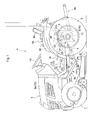
- Fig. 1 is a side view showing an entire tractor as one example of the work vehicle according to one embodiment of the present invention.
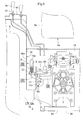
- Fig. 2 is a plan view showing the entire tractor according to the embodiment of the present invention.
- the tractor according to the embodiment of the present invention is a self-propelled vehicle including: a pair of right and left drivable and steerable front wheels 1,1; a pair of right and left drivable rear wheels 2,2; a motor part 3 disposed in a front part of a vehicle body; and a driving part 4 disposed in a rear part of the vehicle body.
- the tractor is provided with a power take off shaft 6 (hereinbelow, referred to as "rear PTO 6") disposed in a rear part of a transmission case 5 positioned in the rear part of the vehicle body, and a power take off shaft 7 (hereinbelow, referred to as "mid PTO 7”) disposed in a lower portion of the transmission case 5.
- a power take off shaft 6 hereinbelow, referred to as "rear PTO 6”
- mid PTO 7 disposed in a lower portion of the transmission case 5.
- the tractor may be used as various kinds of riding type work machine by liftably and drivably connecting various working devices.
- the tractor may be used as a riding type mower, by liftably connecting a mower 8 through a link mechanism 9a to the self-propelled vehicle body between the front wheels and the rear wheels and allowing a driving force of an engine 3a disposed in the motor part 3 to be transmitted from the mid PTO 7 to the mower 8.
- the tractor may be used as a riding type tiller, by liftably connecting a rotary tilling device (not shown) through a link mechanism 9b to the rear part of the self-propelled vehicle body and allowing a driving force of the engine 3 a to be transmitted from the rear PTO 6 to the rotary tilling device.
- a body frame 10 of the self-propelled vehicle is formed of: the engine 3a disposed in the motor part 3; a main frame 11 which is connected to a lower part of the engine 3a and extending in a longitudinal direction of the vehicle body; and the transmission case 5 connected to a rear part of the main frame 11.
- the body frame 10 is provided with a pair of right and left rear wheel drive cases 12,12 flanking the transmission case 5 in such a manner that each case 12 extends outward from a corresponding lateral side of the transmission case 5 in a transversal direction of the vehicle body, and each rear wheel drive case 12 supports the corresponding rear wheel 2 through a rear axle.
- the rear wheel drive case 12 includes: a base end side case 12a formed integrally with a lateral wall of the transmission case 5; and a distal end side case 12b whose one end is detachably connected to the base end side case 12a.
- the driving part 4 includes: a driver's seat 4a provided above the transmission case 5; a steeling wheel 15 provided frontward of the driver's seat 4a; a pair of left and right brake pedals 17a,17b provided in a right end part on a front end side of a driving part floor 16; and a brake operation tool 18 and a PTO selection lever 19 each of which is in a shape of a lever and provided in the vicinity of the driver's seat 4a.
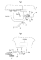
- Fig. 3 is a plan view showing a structure for brake operation.
- Fig. 4 is a side view showing the structure for brake operation.
- the left brake pedal 17a from between a pair of the right and left brake pedals 17a,17b is swingably supported on the main frame 11 through a shaft 21 which is extending in the transversal direction of the vehicle body and connected rotatably in a unified manner to a boss 20 of a pedal arm through a connecting pin 20a.
- the boss 20 of a pedal arm of the right brake pedal 17b from between a pair of the left and right brake pedals 17a,17b is relatively rotatably fitted onto the shaft 21, and the right brake pedal 17b is swingably supported on the main frame 11 through the shaft 21 and swingably operable independently of the left brake pedal 17a.
- a pedal 17c relatively rotatably supported on the shaft 21 is for operating a main clutch (not shown).
- the (left and right) brake pedals 17a, 17b separately interlock with respective (left and right) swing arm-shaped operation parts 22a of respective (left and right) traveling brakes 22,22 provided inside the transmission case 5 through respective (left and right) traveling brake interlocking mechanisms 24,24.
- Each of the (left or right) traveling brake 22 independently exerts a braking action on the corresponding (left or right) rear axle to separately apply brake on the corresponding (left or right) rear wheel 2.
- the traveling brake interlocking mechanism 24 corresponding to the left brake pedal 17a includes: a swing arm 25 provided rotatably in a unified manner on an end part of the shaft 21 which is opposite to the end part to which the brake pedal 17a is connected; and a corresponding interlocking rod 26 which extends in the longitudinal direction of the vehicle body, whose front end part is relatively rotatably connected to a free end side of the corresponding swing arm 25 and whose rear end part is relatively rotatably connected to the operation part 22a of the corresponding traveling brake 22 through a joint.
- the interlocking rod 26 is disposed on a left outer side of the main frame 11 and extends under the driving part floor 16.
- the traveling brake interlocking mechanism 24 corresponding to the right brake pedal 17b includes: the swing arm 25 provided rotatably in a unified manner on the boss 20 of the brake pedal 17b; and the corresponding interlocking rod 26 which extends in the longitudinal direction of the vehicle body, whose front end part is relatively rotatably connected to a free end side of the corresponding swing arm 25 and whose rear end part is relatively rotatably connected to the operation part 22a of the corresponding traveling brake 22 through the joint.
- the interlocking rod 26 is disposed on a right outer side of the main frame 11 and extends under the driving part floor 16.
- the left traveling brake 22 can be put to an on-state so as to apply brake on the left rear wheel 2.
- the right traveling brake 22 can be put to an on-state so as to apply brake on the right rear wheel 2.
- a mounting member 28 is fixed to a support part 29 provided on the lateral side of the transmission case 5 inside a transmission case cover 13 forming a seat supporting stage, and is connected relatively rotatably about an operation axis P to a base part of the brake operation tool 18.
- the brake operation tool 18 passes through a through hole 13a formed in the transmission case cover 13, and is operable swingably in a vertical direction about the operation axis P by a grip 18b disposed outside of the transmission case cover 13. As shown in Figs.
- the support part 29 for supporting the brake operation tool 18 on a transmission case 5-side includes: a plate member forming a connection seat 29a detachably connected to the transmission case 5 by connecting bolts; a plate member forming an operation tool support part 29b to which the mounting member 28 of the brake operation tool 18 is connected; and a bent rod in a shape of U when seen from above which serves as a connection body 29c connecting the connection seat 29a and the operation tool support part 29b.
- the brake operation tool 18 is connected to the operation parts 22a of a pair of the right and left traveling brakes 22,22 through an interlocking mechanism 30.
- the interlocking mechanism 30 includes: a pair of right and left swing interlocking members (moving bodies) 31,31 flanking the transmission case 5; an interlocking body 32 made of sheet metal for connecting a free end side of one of the swing interlocking members 31 to an arm part 18a of the brake operation tool 18; a pair of right and left interlocking rods 33,33 each of which includes a round bar for independently interlocking a free end side of the corresponding (right or left) swing interlocking member 31 with the operation part 22a of the corresponding (right or left) traveling brake 22; and the single shaft 34 which is extending in the transversal direction of the vehicle body and connected rotatably in a unified manner to base parts of a pair of the right and left swing interlocking members 31,31.
- the interlocking mechanism 30 for transmitting the operational displacement of the brake operation tool 18 to the parking brake 22B is disposed along a lateral side of the transmission case 5, the space is effectively utilized
- the shaft 34 of a pair of the right and left swing interlocking members 31,31 is rotatably supported on a support part 35 formed of a cylindrical body which is provided on the main frame 11 and extending in the transversal direction of the vehicle body under the transmission case 5.
- a pair of the right and left swing interlocking members 31,31 are supported swingably in the longitudinal direction of the vehicle body about a swing axis X of the shaft 34, each of which is disposed at a position between the transmission case 5 and a corresponding rear wheel fender 36 located on a corresponding side of the transmission case 5 and frontward of the rear wheel drive case 12 in the longitudinal direction of the vehicle body.
- the interlocking rod 33 is slidably inserted into a through hole 31b formed in a connecting portion 31a as a plate body provided on the swing interlocking member 31, and a receiving part 33a as a cylindrical body attached to an end part of the interlocking rod 33 extending frontward of the connecting portion 31a,
- a connection structure between the right swing interlocking member 31 and the corresponding interlocking rod 33 is slidably inserted into a through hole 31b formed in a connecting portion 31a as a plate body provided on the swing interlocking member 31, and a receiving part 33a as a cylindrical body attached to an end part of the interlocking rod 33 extending frontward of the connecting portion 31a.
- the swing interlocking member 31 and the interlocking rod 33 are connected in such a manner that, when the swing interlocking member 31 is operated to swing frontward ("brake-on" side), the connecting portion 31a of the swing interlocking member 31 is brought into contact with the receiving part 33a and the swing interlocking member 31 pulls frontward the interlocking rod 33.
- the swing interlocking member 31 and the interlocking rod 33 are connected in such a manner that, when the brake pedals 17a,17b are depressed, in conjunction with the interlocking rod 26, the interlocking rod 33 moves through the through hole 31b frontward relatively to the swing interlocking member 31 so as to allow the operation of the brake pedals 17a,17b to put the traveling brake 22 into the on-state.
- Fig. 5 is a side view illustrating the on-state of the traveling brake 22 made by the brake operation tool 18.
- the interlocking body 32 is pulled and swingably frontward operate the first swing interlocking member 31 on the same side of the vehicle body.
- the second swing interlocking member 31 on the other side is swung frontward.
- the interlocking rod 33 connected to the first swing interlocking member 31 is pulled by the first swing interlocking member 31, and the operation part 22a of the traveling brake 22 on this side is swung to the "brake-on" side.
- the interlocking rod 33 connected to the second swing interlocking member 31 on the other side is pulled by the second swing interlocking member 31, and the operation part 22a of the traveling brake 22 on the other side is swung to the "brake-on" side.
- a latchet claw 38a of a ratchet type lock mechanism 38 provided between the brake operation tool 18 and the mounting member 28 engages with a portion in a serrated part of a locking body 38b corresponding to an operation position of the brake operation tool 18 to put the lock mechanism 38 into a locking state in which the brake operation tool 18 is fixed at a "brake-on" position and a pair of the right and left traveling brakes 22,22 are kept in the on-state against a returning force to the off-state.
- a pair of the right and left traveling brakes 22,22 serve as a parking brake 22B, and by operating the brake operation tool 18 swingably in the upward direction about the operation axis P, a pair of the right and left parking brakes 22B,22B are put into the on-state in which the parking brake is applied on a pair of the right and left rear wheels 2,2.
- the lock mechanism 38 cancels the engagement of the latchet claw 38a relative to the serrated part of the locking body 38b, to be in a lock cancel state.
- the PTO selection lever 19 is interlocked with a speed change operation part of a working speed changer (not shown) provided inside the transmission case 5, so as to allow variable speed drive of the mid PTO 7 and the rear PTO 6.
- Fig. 9 is a plan view showing operation positions of the PTO selection lever 19.
- Fig. 10 is a side view showing the operation positions of the PTO selection lever 19.
- the PTO selection lever 19 is supported in such a manner that it is operable swingably in the longitudinal direction of the vehicle body along a guide trench 41 of a lever guide 40 provided in the rear wheel fender 36 and switchable among a front-rear working position FR, a stop position S and a rear working position R.
- the working speed changer (not shown) is put into a speed change state in which a power is transmitted to the mid PTO 7 and the rear PTO 6, and the mid PTO 7 and the rear PTO 6 become drivable at a predetermined rotational rate.
- the working speed changer is put into a neutral state in which the power transmission to the mid PTO 7 and the rear PTO 6 is stopped and the driving of the mid PTO 7 and the rear PTO 6 becomes impossible.
- the working speed changer When the PTO selection lever 19 is operated to the rear working position R, the working speed changer is put into a speed change state in which the power transmission to the mid PTO 7 is stopped but a power is transmitted to the rear PTO 6 and thus the rear PTO 6 becomes drivable while the mid PTO 7 is stopped. In this case, the rotational rate of the rear PTO 6 becomes lower as compared with a case where the PTO selection lever 19 is at the front-rear working position FR.
- the self-propelled vehicle includes: an engine start blocking device 45; an engine automatic stopping device 46; and an engine stop blocking device 47.
- Fig. 11 is an electric circuit diagram showing the engine start blocking device 45, the engine automatic stopping device 46 and the engine stop blocking device 47.
- the engine start blocking device 45 includes: a controller 51 coordinated with an engine starter 50; a working clutch detection switch 52 coordinated with the controller 51; a seat detection switch 53; and a running speed change detection switch 54.
- the working clutch detection switch 52 is for detecting an off-state of a working clutch (not shown) which is provided inside the transmission case 5 and configured to connect and disconnect a power transmission from the engine 3a to the mid PTO 7 and the rear PTO 6, and outputting the detection result to the controller 51.
- the seat detection switch 53 is for detecting a seated state of the driver's seat 4a and outputting the detection result to the controller 51.
- the running speed change detection switch 54 is for detecting a neutral state of a running speed changer (not shown) which is provided inside the transmission case 5 and is configured to allow variable speed drive of the front wheels 1 and the rear wheels 2, and outputting the detection result to the controller 51.
- the controller 51 utilizes a microcomputer and includes a start blocking means 55.
- the start blocking means 55 detects a driving operation of the engine starter 50 based on information from a main switch 56, if the start blocking means 55 determines that the working clutch is not in the off-state based on detection information from the working clutch detection switch 52, or if determines that the driver's seat 4a is not in the seated state based on detection information from the seat detection switch 53, or if determines that the running speed changer is not in the neutral state based on detection information from the running speed change detection switch 54, the start blocking means 55 blocks the driving of the engine starter 50 by an engine starting means 57; and if the start blocking means 55 determines that the working clutch is in the off-state, that the driver's seat 4a is in the seated state and that the running speed changer is in the neutral state, the start blocking means 55 allows the driving of the engine starter 50 by the engine starting means 57.
- the engine start blocking device 45 is not actuated, and by operating the main switch 56 to an engine start position, the engine 3a can be started.
- the engine start blocking device 45 is actuated and thus the engine 3a never starts even by the operation of the main switch 56 to the engine start position.
- the engine automatic stopping device 46 includes: the controller 51; the seat detection switch 53; an engine detection circuit 58 coordinated with the controller 51; and a key stop solenoid 59.
- the engine detection circuit 58 includes a relay switch 58a coordinated with an L-terminal 60a of an alternator 60.
- the relay switch 58a is switched to an on-state when the engine 3a is not running and there is a current flow in the L-terminal 60a, while switched to an off-state when the engine 3a is running and there is no current flow in the L-terminal 60a.
- the engine detection circuit 58 detects that the engine 3a is running based on the absence of current in the L-terminal 60a, and outputs this detection result to the controller 51.
- the controller 51 includes an engine stopping means 61.
- the engine stopping means 61 is configured to determine whether or not the driver's seat 4a is in the seated state, based on the detection information from the seat detection switch 53.
- an operation switch 59a formed of a relay switch of the key stop solenoid 59 is turned on to actuate the key stop solenoid 59.
- the key stop solenoid 59 switches the key switch to an engine stop position to stop the engine 3a.
- a charge lamp 62 is parallelly connected to the engine detection circuit 58.
- the engine automatic stopping device 46 is actuated and stops the engine 3a.
- the engine stop blocking device 47 includes: the controller 51; and a detection circuit 63 coordinated with the controller 51.
- the detection circuit 63 includes: a PTO selection switch 64; and a detection switch 65 for the parking brake.
- the detection switch 65 for the parking brake is configured to detect the on-state of the parking brake 22B and output the detection result to the controller 51.
- the PTO selection switch 64 is provided on a back face of the lever guide 40 for the PTO selection lever 19.
- a detection body 64a is brought into contact with the PTO selection lever 19 and pressed, to thereby switch the PTO selection switch 64 into the on-state.
- the detection result is output to the controller 51.
- the detection body 64a of the PTO selection switch 64 overlaps an operation pathway of the PTO selection lever 19 so as to be visually checked through the guide trench 41 of the lever guide 40, and the switching can be easily visually checked through confirming whether or not the PTO selection switch 64 is brought into contact with the PTO selection lever 19.
- a stopper 42 is disposed in the operation pathway of the PTO selection lever 19. Since the stopper 42 provides the positioning of the PTO selection lever 19 at the rear working position R, the PTO selection lever 19 can be shifted to the rear working position R with high precision, and at the same time, the PTO selection switch 64 can perform detection with high precision.
- the controller 51 includes a stop blocking means 66.
- the stop blocking means 66 is configured to determine whether or not the rear PTO 6 is in the drivable state based on detection information from the PTO selection switch 64, and whether or not the parking brake 22B is in the on-state based on detection information from the detection switch 65 for the parking brake, and to block the actuation of the engine stopping means 61 when it is determined that the rear PTO 6 is in the drivable state and at the same time the parking brake 22B is in the on-state.
- the detection switch 65 for the parking brake is disposed at a position above the rear wheel drive case 12 extending from the transmission case 5, inside relative to a vertical wall (downward extending wall) 36a of the rear wheel fender 36 in the transversal direction of the vehicle body, at a lower height level than that of a lower end 4b of the driver's seat 4a, rearward of the swing interlocking member 31 of the interlocking mechanism 30.
- the detection switch 65 is configured to detect the on-state of the parking brake 22B based on a swing position of the swing interlocking member 31.
- the detection switch 65 for detecting the movement of the swing interlocking member 31 configured to move in accordance with the operational displacement in the interlocking mechanism 30 is disposed in a space S having right and left lateral faces and a bottom face defined by the vertical wall 36a of the rear wheel fender 36, the transmission case 5 and the rear wheel drive case 12.
- the detection switch 65 includes a case portion 65a and a detecting portion 65b in a shape of a pin provided frontward of the case portion 65a, and is supported by the connection body 29c of the support part 29 of the transmission case 5 through a mounting member 70 in such a manner that the detecting portion 65b is positioned in a moving pathway of a detected portion 31c in a shape of a vertical plate which is provided to a free end part (upper end part) of the swing interlocking member 31 and extending inward of the vehicle body.
- Figs. 5 and 7 illustrate a detecting state of the detection switch 65.
- a switching mechanism (not shown) disposed inside the case portion 65a is switched to the on-state, and the detection switch 65 is put into the detecting state.
- the detection switch 65 is disposed as close to the center of the vehicle body as possible so as to overlap the base end side case 12a when seen as a planar view and as high above the support part 29 as possible, in order to prevent mud or grass from attaching or contacting to the detection switch 65.
- Fig. 4 illustrates a non-detecting state of the detection switch 65.
- the swing interlocking member 31 is put at a swing position corresponding to the off-state of the parking brake 22B and the detected portion 31 c of the swing interlocking member 31 is brought into contact with the detecting portion 65b of the detection switch 65 to push the detecting portion 65b, the switching mechanism disposed inside the case portion 65a is switched to the off-state, and the detection switch 65 is put to the non-detecting state.
- the mounting member 70 for the detection switch 65 includes: a support piece 70a extending rearward and obliquely upward relative to the vehicle body under the detecting portion 65b of the detection switch 65 from the connection body 29c of the support part 29 on the transmission case 5; and a connecting piece 70b which is standing on a distal end of the support piece 70a and connected to the case portion 65a of the detection switch 65. Therefore, the mounting member 70, especially the support piece 70a, blocks mud or grass so as to prevent them from attaching or contacting to the detecting portion 65b of the detection switch 65.
- Fig. 12 is a side view showing the brake operation tool 18 according to another embodiment.
- Fig. 13 is a front view showing the brake operation tool 18 according to another embodiment.
- the brake operation tool 18 according to another embodiment includes a brake pedal swingably supported on a shaft 74 attached to the lateral side of the transmission case 5 through a supporting member 73.
- the brake operation tool 18 is biased to return to the "brake-off" position by a return spring 75 attached to the shaft 74.
- the brake operation tool 18 is provided with a positioning body 76 connected rotatably in a unified manner to the base part of the brake operation tool 18, and is interlocked with the swing interlocking member 31 through the positioning body 76 and an interlocking body 77 that connects the positioning body 76 to the swing interlocking member 31.
- the brake operation tool 18 When depressed to the "brake-on” position, the brake operation tool 18 is locked at the “brake-on” position by a locking lever 79 swingably supported on an upper end part 73a of the supporting member 73 through a shaft 78, and the parking brake 22B is kept in the on-state.
- the locking lever 79 has a latchet claw 80 formed integrally with a base part thereof.
- the locking lever 79 is swingably biased by a locking spring 81, the latchet claw 80 is engaged with a serrated part 82 provided in the positioning body 76, to thereby lock the brake operation tool 18 at the "brake-on" position.
- the locking lever 79 releases the latchet claw 80 from the serrated part 82 to allow the brake operation tool 18 to be raised and return to the "brake-off" position.
- the present invention is applicable to a work vehicle having a detection switch for detecting the operation state of the parking brake so as to block the actuation of the engine automatic stopping device.
- the present invention is also applicable to a work vehicle which has a detection switch for detecting the operating state of the parking brake for different purposes, e.g. detection switch for detecting the operating state of the parking brake so as to control a display for displaying the operating state of the parking brake.
Landscapes
- Engineering & Computer Science (AREA)
- Transportation (AREA)
- Mechanical Engineering (AREA)
- Braking Elements And Transmission Devices (AREA)
- Valves And Accessory Devices For Braking Systems (AREA)
Applications Claiming Priority (1)
| Application Number | Priority Date | Filing Date | Title |
|---|---|---|---|
| JP2010169591A JP5337113B2 (ja) | 2010-07-28 | 2010-07-28 | トラクタ |
Publications (3)
| Publication Number | Publication Date |
|---|---|
| EP2412591A2 true EP2412591A2 (de) | 2012-02-01 |
| EP2412591A3 EP2412591A3 (de) | 2013-06-12 |
| EP2412591B1 EP2412591B1 (de) | 2019-03-27 |
Family
ID=44785183
Family Applications (1)
| Application Number | Title | Priority Date | Filing Date |
|---|---|---|---|
| EP11175217.6A Active EP2412591B1 (de) | 2010-07-28 | 2011-07-25 | Nutzfahrzeugbremse |
Country Status (2)
| Country | Link |
|---|---|
| EP (1) | EP2412591B1 (de) |
| JP (1) | JP5337113B2 (de) |
Cited By (1)
| Publication number | Priority date | Publication date | Assignee | Title |
|---|---|---|---|---|
| EP3991535A4 (de) * | 2019-06-28 | 2023-07-26 | Kubota Corporation | Nutzfahrzeug |
Families Citing this family (2)
| Publication number | Priority date | Publication date | Assignee | Title |
|---|---|---|---|---|
| US10632841B2 (en) | 2016-06-22 | 2020-04-28 | Kubota Corporation | Drive device for PTO shaft of working machine |
| JP6920955B2 (ja) * | 2017-10-10 | 2021-08-18 | 株式会社クボタ | トラクタ |
Citations (1)
| Publication number | Priority date | Publication date | Assignee | Title |
|---|---|---|---|---|
| JPH11321594A (ja) | 1998-05-11 | 1999-11-24 | Kubota Corp | トラクタのブレーキ操作構造 |
Family Cites Families (10)
| Publication number | Priority date | Publication date | Assignee | Title |
|---|---|---|---|---|
| JPS5744558A (en) * | 1980-08-27 | 1982-03-13 | Hino Motors Ltd | Car brake system |
| JPS60161662U (ja) * | 1984-04-04 | 1985-10-26 | 株式会社クボタ | ハンドブレ−キ装置 |
| JPH0452138Y2 (de) * | 1986-02-27 | 1992-12-08 | ||
| US4759417A (en) * | 1986-08-27 | 1988-07-26 | Deere & Company | System and method for controlling the ground speed and enhancing the maneuverability of an off-road vehicle |
| CA1329560C (en) * | 1986-08-27 | 1994-05-17 | Lee Joseph Wanie | System for controlling the ground speed of and enhancing the maneuverability of an off-road vehicle |
| JPH0190663U (de) * | 1987-12-08 | 1989-06-14 | ||
| US6886677B2 (en) * | 2002-10-18 | 2005-05-03 | Deere & Co. | Interlock of parking brake and drive control pedals for utility vehicle |
| JP2004224164A (ja) * | 2003-01-22 | 2004-08-12 | Iseki & Co Ltd | 動力車両 |
| US7021432B2 (en) * | 2004-04-20 | 2006-04-04 | Deere & Company | Park brake linkage |
| JP4673385B2 (ja) * | 2008-02-15 | 2011-04-20 | 株式会社クボタ | トラクタにおけるブレーキランプの点灯操作構造 |
-
2010
- 2010-07-28 JP JP2010169591A patent/JP5337113B2/ja active Active
-
2011
- 2011-07-25 EP EP11175217.6A patent/EP2412591B1/de active Active
Patent Citations (1)
| Publication number | Priority date | Publication date | Assignee | Title |
|---|---|---|---|---|
| JPH11321594A (ja) | 1998-05-11 | 1999-11-24 | Kubota Corp | トラクタのブレーキ操作構造 |
Cited By (2)
| Publication number | Priority date | Publication date | Assignee | Title |
|---|---|---|---|---|
| EP3991535A4 (de) * | 2019-06-28 | 2023-07-26 | Kubota Corporation | Nutzfahrzeug |
| US11926211B2 (en) | 2019-06-28 | 2024-03-12 | Kubota Corporation | Working vehicle |
Also Published As
| Publication number | Publication date |
|---|---|
| EP2412591A3 (de) | 2013-06-12 |
| JP2012030616A (ja) | 2012-02-16 |
| JP5337113B2 (ja) | 2013-11-06 |
| EP2412591B1 (de) | 2019-03-27 |
Similar Documents
| Publication | Publication Date | Title |
|---|---|---|
| JP2003072528A (ja) | 乗用型草刈り機 | |
| EP2412591B1 (de) | Nutzfahrzeugbremse | |
| JP2017039339A (ja) | 作業車輌 | |
| JP6335840B2 (ja) | 作業車 | |
| JP4764437B2 (ja) | トラクタのブレーキ操作機構 | |
| JP7542498B2 (ja) | 作業車 | |
| JP4673385B2 (ja) | トラクタにおけるブレーキランプの点灯操作構造 | |
| JP4141306B2 (ja) | 乗用作業機 | |
| JP3776035B2 (ja) | 農作業機 | |
| EP1792796A1 (de) | Bremsbetätigungsvorrichtung von fahrzeug | |
| KR20120109288A (ko) | 작업기의 조작 장치 | |
| JP2015146815A (ja) | 作業機の操作装置 | |
| KR100397852B1 (ko) | 차량의 파킹 브레이크 시스템 | |
| CN101179926B (zh) | 载人型插秧机 | |
| JP4202462B2 (ja) | 小型乗用作業機 | |
| KR101319896B1 (ko) | 승용형 이앙기 | |
| JP7234827B2 (ja) | 作業車両 | |
| JP4634910B2 (ja) | トラクタの乗降部構造 | |
| JP2019196133A (ja) | 作業車両 | |
| JP2012116290A (ja) | 作業車両の駐車ブレーキ操作装置 | |
| JP7022092B2 (ja) | 作業車両 | |
| JPH09254748A (ja) | 歩行型農用作業車 | |
| JP3759817B2 (ja) | 作業車 | |
| JP4388651B2 (ja) | 田植機 | |
| JP2003040150A (ja) | 乗用管理機 |
Legal Events
| Date | Code | Title | Description |
|---|---|---|---|
| 17P | Request for examination filed |
Effective date: 20110725 |
|
| AK | Designated contracting states |
Kind code of ref document: A2 Designated state(s): AL AT BE BG CH CY CZ DE DK EE ES FI FR GB GR HR HU IE IS IT LI LT LU LV MC MK MT NL NO PL PT RO RS SE SI SK SM TR |
|
| AX | Request for extension of the european patent |
Extension state: BA ME |
|
| PUAI | Public reference made under article 153(3) epc to a published international application that has entered the european phase |
Free format text: ORIGINAL CODE: 0009012 |
|
| PUAL | Search report despatched |
Free format text: ORIGINAL CODE: 0009013 |
|
| AK | Designated contracting states |
Kind code of ref document: A3 Designated state(s): AL AT BE BG CH CY CZ DE DK EE ES FI FR GB GR HR HU IE IS IT LI LT LU LV MC MK MT NL NO PL PT RO RS SE SI SK SM TR |
|
| AX | Request for extension of the european patent |
Extension state: BA ME |
|
| RIC1 | Information provided on ipc code assigned before grant |
Ipc: B60T 7/08 20060101ALI20130508BHEP Ipc: B60T 7/10 20060101AFI20130508BHEP |
|
| RBV | Designated contracting states (corrected) |
Designated state(s): AL AT BE BG CH CY CZ DE DK EE ES FI FR GB GR HR HU IE IS IT LI LT LU LV MC MK MT NL NO PL PT RO RS SE SI SK SM TR |
|
| GRAP | Despatch of communication of intention to grant a patent |
Free format text: ORIGINAL CODE: EPIDOSNIGR1 |
|
| STAA | Information on the status of an ep patent application or granted ep patent |
Free format text: STATUS: GRANT OF PATENT IS INTENDED |
|
| INTG | Intention to grant announced |
Effective date: 20181109 |
|
| GRAS | Grant fee paid |
Free format text: ORIGINAL CODE: EPIDOSNIGR3 |
|
| GRAA | (expected) grant |
Free format text: ORIGINAL CODE: 0009210 |
|
| STAA | Information on the status of an ep patent application or granted ep patent |
Free format text: STATUS: THE PATENT HAS BEEN GRANTED |
|
| AK | Designated contracting states |
Kind code of ref document: B1 Designated state(s): AL AT BE BG CH CY CZ DE DK EE ES FI FR GB GR HR HU IE IS IT LI LT LU LV MC MK MT NL NO PL PT RO RS SE SI SK SM TR |
|
| REG | Reference to a national code |
Ref country code: GB Ref legal event code: FG4D |
|
| REG | Reference to a national code |
Ref country code: CH Ref legal event code: EP |
|
| REG | Reference to a national code |
Ref country code: AT Ref legal event code: REF Ref document number: 1112675 Country of ref document: AT Kind code of ref document: T Effective date: 20190415 |
|
| REG | Reference to a national code |
Ref country code: IE Ref legal event code: FG4D |
|
| REG | Reference to a national code |
Ref country code: DE Ref legal event code: R096 Ref document number: 602011057462 Country of ref document: DE |
|
| PG25 | Lapsed in a contracting state [announced via postgrant information from national office to epo] |
Ref country code: FI Free format text: LAPSE BECAUSE OF FAILURE TO SUBMIT A TRANSLATION OF THE DESCRIPTION OR TO PAY THE FEE WITHIN THE PRESCRIBED TIME-LIMIT Effective date: 20190327 Ref country code: LT Free format text: LAPSE BECAUSE OF FAILURE TO SUBMIT A TRANSLATION OF THE DESCRIPTION OR TO PAY THE FEE WITHIN THE PRESCRIBED TIME-LIMIT Effective date: 20190327 Ref country code: NO Free format text: LAPSE BECAUSE OF FAILURE TO SUBMIT A TRANSLATION OF THE DESCRIPTION OR TO PAY THE FEE WITHIN THE PRESCRIBED TIME-LIMIT Effective date: 20190627 Ref country code: SE Free format text: LAPSE BECAUSE OF FAILURE TO SUBMIT A TRANSLATION OF THE DESCRIPTION OR TO PAY THE FEE WITHIN THE PRESCRIBED TIME-LIMIT Effective date: 20190327 |
|
| REG | Reference to a national code |
Ref country code: NL Ref legal event code: MP Effective date: 20190327 |
|
| PG25 | Lapsed in a contracting state [announced via postgrant information from national office to epo] |
Ref country code: LV Free format text: LAPSE BECAUSE OF FAILURE TO SUBMIT A TRANSLATION OF THE DESCRIPTION OR TO PAY THE FEE WITHIN THE PRESCRIBED TIME-LIMIT Effective date: 20190327 Ref country code: RS Free format text: LAPSE BECAUSE OF FAILURE TO SUBMIT A TRANSLATION OF THE DESCRIPTION OR TO PAY THE FEE WITHIN THE PRESCRIBED TIME-LIMIT Effective date: 20190327 Ref country code: HR Free format text: LAPSE BECAUSE OF FAILURE TO SUBMIT A TRANSLATION OF THE DESCRIPTION OR TO PAY THE FEE WITHIN THE PRESCRIBED TIME-LIMIT Effective date: 20190327 Ref country code: GR Free format text: LAPSE BECAUSE OF FAILURE TO SUBMIT A TRANSLATION OF THE DESCRIPTION OR TO PAY THE FEE WITHIN THE PRESCRIBED TIME-LIMIT Effective date: 20190628 Ref country code: BG Free format text: LAPSE BECAUSE OF FAILURE TO SUBMIT A TRANSLATION OF THE DESCRIPTION OR TO PAY THE FEE WITHIN THE PRESCRIBED TIME-LIMIT Effective date: 20190627 Ref country code: NL Free format text: LAPSE BECAUSE OF FAILURE TO SUBMIT A TRANSLATION OF THE DESCRIPTION OR TO PAY THE FEE WITHIN THE PRESCRIBED TIME-LIMIT Effective date: 20190327 |
|
| REG | Reference to a national code |
Ref country code: AT Ref legal event code: MK05 Ref document number: 1112675 Country of ref document: AT Kind code of ref document: T Effective date: 20190327 |
|
| PG25 | Lapsed in a contracting state [announced via postgrant information from national office to epo] |
Ref country code: EE Free format text: LAPSE BECAUSE OF FAILURE TO SUBMIT A TRANSLATION OF THE DESCRIPTION OR TO PAY THE FEE WITHIN THE PRESCRIBED TIME-LIMIT Effective date: 20190327 Ref country code: PT Free format text: LAPSE BECAUSE OF FAILURE TO SUBMIT A TRANSLATION OF THE DESCRIPTION OR TO PAY THE FEE WITHIN THE PRESCRIBED TIME-LIMIT Effective date: 20190727 Ref country code: ES Free format text: LAPSE BECAUSE OF FAILURE TO SUBMIT A TRANSLATION OF THE DESCRIPTION OR TO PAY THE FEE WITHIN THE PRESCRIBED TIME-LIMIT Effective date: 20190327 Ref country code: CZ Free format text: LAPSE BECAUSE OF FAILURE TO SUBMIT A TRANSLATION OF THE DESCRIPTION OR TO PAY THE FEE WITHIN THE PRESCRIBED TIME-LIMIT Effective date: 20190327 Ref country code: RO Free format text: LAPSE BECAUSE OF FAILURE TO SUBMIT A TRANSLATION OF THE DESCRIPTION OR TO PAY THE FEE WITHIN THE PRESCRIBED TIME-LIMIT Effective date: 20190327 Ref country code: SK Free format text: LAPSE BECAUSE OF FAILURE TO SUBMIT A TRANSLATION OF THE DESCRIPTION OR TO PAY THE FEE WITHIN THE PRESCRIBED TIME-LIMIT Effective date: 20190327 Ref country code: AL Free format text: LAPSE BECAUSE OF FAILURE TO SUBMIT A TRANSLATION OF THE DESCRIPTION OR TO PAY THE FEE WITHIN THE PRESCRIBED TIME-LIMIT Effective date: 20190327 Ref country code: IT Free format text: LAPSE BECAUSE OF FAILURE TO SUBMIT A TRANSLATION OF THE DESCRIPTION OR TO PAY THE FEE WITHIN THE PRESCRIBED TIME-LIMIT Effective date: 20190327 |
|
| PG25 | Lapsed in a contracting state [announced via postgrant information from national office to epo] |
Ref country code: SM Free format text: LAPSE BECAUSE OF FAILURE TO SUBMIT A TRANSLATION OF THE DESCRIPTION OR TO PAY THE FEE WITHIN THE PRESCRIBED TIME-LIMIT Effective date: 20190327 Ref country code: PL Free format text: LAPSE BECAUSE OF FAILURE TO SUBMIT A TRANSLATION OF THE DESCRIPTION OR TO PAY THE FEE WITHIN THE PRESCRIBED TIME-LIMIT Effective date: 20190327 |
|
| PG25 | Lapsed in a contracting state [announced via postgrant information from national office to epo] |
Ref country code: IS Free format text: LAPSE BECAUSE OF FAILURE TO SUBMIT A TRANSLATION OF THE DESCRIPTION OR TO PAY THE FEE WITHIN THE PRESCRIBED TIME-LIMIT Effective date: 20190727 Ref country code: AT Free format text: LAPSE BECAUSE OF FAILURE TO SUBMIT A TRANSLATION OF THE DESCRIPTION OR TO PAY THE FEE WITHIN THE PRESCRIBED TIME-LIMIT Effective date: 20190327 |
|
| REG | Reference to a national code |
Ref country code: DE Ref legal event code: R097 Ref document number: 602011057462 Country of ref document: DE |
|
| PG25 | Lapsed in a contracting state [announced via postgrant information from national office to epo] |
Ref country code: DK Free format text: LAPSE BECAUSE OF FAILURE TO SUBMIT A TRANSLATION OF THE DESCRIPTION OR TO PAY THE FEE WITHIN THE PRESCRIBED TIME-LIMIT Effective date: 20190327 |
|
| REG | Reference to a national code |
Ref country code: DE Ref legal event code: R119 Ref document number: 602011057462 Country of ref document: DE |
|
| PLBE | No opposition filed within time limit |
Free format text: ORIGINAL CODE: 0009261 |
|
| STAA | Information on the status of an ep patent application or granted ep patent |
Free format text: STATUS: NO OPPOSITION FILED WITHIN TIME LIMIT |
|
| PG25 | Lapsed in a contracting state [announced via postgrant information from national office to epo] |
Ref country code: SI Free format text: LAPSE BECAUSE OF FAILURE TO SUBMIT A TRANSLATION OF THE DESCRIPTION OR TO PAY THE FEE WITHIN THE PRESCRIBED TIME-LIMIT Effective date: 20190327 Ref country code: MC Free format text: LAPSE BECAUSE OF FAILURE TO SUBMIT A TRANSLATION OF THE DESCRIPTION OR TO PAY THE FEE WITHIN THE PRESCRIBED TIME-LIMIT Effective date: 20190327 |
|
| REG | Reference to a national code |
Ref country code: CH Ref legal event code: PL |
|
| 26N | No opposition filed |
Effective date: 20200103 |
|
| GBPC | Gb: european patent ceased through non-payment of renewal fee |
Effective date: 20190725 |
|
| PG25 | Lapsed in a contracting state [announced via postgrant information from national office to epo] |
Ref country code: TR Free format text: LAPSE BECAUSE OF FAILURE TO SUBMIT A TRANSLATION OF THE DESCRIPTION OR TO PAY THE FEE WITHIN THE PRESCRIBED TIME-LIMIT Effective date: 20190327 |
|
| REG | Reference to a national code |
Ref country code: BE Ref legal event code: MM Effective date: 20190731 |
|
| PG25 | Lapsed in a contracting state [announced via postgrant information from national office to epo] |
Ref country code: DE Free format text: LAPSE BECAUSE OF NON-PAYMENT OF DUE FEES Effective date: 20200201 Ref country code: GB Free format text: LAPSE BECAUSE OF NON-PAYMENT OF DUE FEES Effective date: 20190725 |
|
| PG25 | Lapsed in a contracting state [announced via postgrant information from national office to epo] |
Ref country code: LI Free format text: LAPSE BECAUSE OF NON-PAYMENT OF DUE FEES Effective date: 20190731 Ref country code: CH Free format text: LAPSE BECAUSE OF NON-PAYMENT OF DUE FEES Effective date: 20190731 Ref country code: LU Free format text: LAPSE BECAUSE OF NON-PAYMENT OF DUE FEES Effective date: 20190725 Ref country code: BE Free format text: LAPSE BECAUSE OF NON-PAYMENT OF DUE FEES Effective date: 20190731 |
|
| PG25 | Lapsed in a contracting state [announced via postgrant information from national office to epo] |
Ref country code: IE Free format text: LAPSE BECAUSE OF NON-PAYMENT OF DUE FEES Effective date: 20190725 |
|
| PG25 | Lapsed in a contracting state [announced via postgrant information from national office to epo] |
Ref country code: CY Free format text: LAPSE BECAUSE OF FAILURE TO SUBMIT A TRANSLATION OF THE DESCRIPTION OR TO PAY THE FEE WITHIN THE PRESCRIBED TIME-LIMIT Effective date: 20190327 |
|
| PG25 | Lapsed in a contracting state [announced via postgrant information from national office to epo] |
Ref country code: MT Free format text: LAPSE BECAUSE OF FAILURE TO SUBMIT A TRANSLATION OF THE DESCRIPTION OR TO PAY THE FEE WITHIN THE PRESCRIBED TIME-LIMIT Effective date: 20190327 Ref country code: HU Free format text: LAPSE BECAUSE OF FAILURE TO SUBMIT A TRANSLATION OF THE DESCRIPTION OR TO PAY THE FEE WITHIN THE PRESCRIBED TIME-LIMIT; INVALID AB INITIO Effective date: 20110725 |
|
| PG25 | Lapsed in a contracting state [announced via postgrant information from national office to epo] |
Ref country code: MK Free format text: LAPSE BECAUSE OF FAILURE TO SUBMIT A TRANSLATION OF THE DESCRIPTION OR TO PAY THE FEE WITHIN THE PRESCRIBED TIME-LIMIT Effective date: 20190327 |
|
| PGFP | Annual fee paid to national office [announced via postgrant information from national office to epo] |
Ref country code: FR Payment date: 20250610 Year of fee payment: 15 |