EP2403050A1 - Batterie von elektrochemischen Generatoren, die einen Schaumstoff als Füllmaterial zwischen Generatoren umfasst - Google Patents
Batterie von elektrochemischen Generatoren, die einen Schaumstoff als Füllmaterial zwischen Generatoren umfasst Download PDFInfo
- Publication number
- EP2403050A1 EP2403050A1 EP11169991A EP11169991A EP2403050A1 EP 2403050 A1 EP2403050 A1 EP 2403050A1 EP 11169991 A EP11169991 A EP 11169991A EP 11169991 A EP11169991 A EP 11169991A EP 2403050 A1 EP2403050 A1 EP 2403050A1
- Authority
- EP
- European Patent Office
- Prior art keywords
- container
- foam
- generators
- generator
- battery
- Prior art date
- Legal status (The legal status is an assumption and is not a legal conclusion. Google has not performed a legal analysis and makes no representation as to the accuracy of the status listed.)
- Granted
Links
- 239000006260 foam Substances 0.000 title claims abstract description 100
- 239000000463 material Substances 0.000 title claims abstract description 18
- 238000011049 filling Methods 0.000 title claims description 11
- WHXSMMKQMYFTQS-UHFFFAOYSA-N Lithium Chemical compound [Li] WHXSMMKQMYFTQS-UHFFFAOYSA-N 0.000 claims abstract description 19
- 229910052744 lithium Inorganic materials 0.000 claims abstract description 19
- 239000003063 flame retardant Substances 0.000 claims abstract description 17
- -1 flame-retardant compound Chemical class 0.000 claims abstract description 15
- 229920001971 elastomer Polymers 0.000 claims abstract description 13
- 239000000806 elastomer Substances 0.000 claims abstract description 13
- HBBGRARXTFLTSG-UHFFFAOYSA-N Lithium ion Chemical compound [Li+] HBBGRARXTFLTSG-UHFFFAOYSA-N 0.000 claims abstract description 11
- 229910001416 lithium ion Inorganic materials 0.000 claims abstract description 11
- 229920003023 plastic Polymers 0.000 claims abstract description 10
- 239000004033 plastic Substances 0.000 claims abstract description 10
- 229920002635 polyurethane Polymers 0.000 claims description 15
- 239000004814 polyurethane Substances 0.000 claims description 15
- 239000011810 insulating material Substances 0.000 claims description 9
- LOOCNDFTHKSTFY-UHFFFAOYSA-N 1,1,2-trichloropropyl dihydrogen phosphate Chemical compound CC(Cl)C(Cl)(Cl)OP(O)(O)=O LOOCNDFTHKSTFY-UHFFFAOYSA-N 0.000 claims description 8
- VTYYLEPIZMXCLO-UHFFFAOYSA-L Calcium carbonate Chemical compound [Ca+2].[O-]C([O-])=O VTYYLEPIZMXCLO-UHFFFAOYSA-L 0.000 claims description 8
- 239000000203 mixture Substances 0.000 claims description 8
- 229920000877 Melamine resin Polymers 0.000 claims description 7
- JDSHMPZPIAZGSV-UHFFFAOYSA-N melamine Chemical compound NC1=NC(N)=NC(N)=N1 JDSHMPZPIAZGSV-UHFFFAOYSA-N 0.000 claims description 7
- 229920005862 polyol Polymers 0.000 claims description 7
- TZCXTZWJZNENPQ-UHFFFAOYSA-L barium sulfate Chemical compound [Ba+2].[O-]S([O-])(=O)=O TZCXTZWJZNENPQ-UHFFFAOYSA-L 0.000 claims description 6
- 230000000284 resting effect Effects 0.000 claims description 6
- 239000004593 Epoxy Substances 0.000 claims description 5
- 239000000945 filler Substances 0.000 claims description 5
- OAICVXFJPJFONN-UHFFFAOYSA-N Phosphorus Chemical compound [P] OAICVXFJPJFONN-UHFFFAOYSA-N 0.000 claims description 4
- 239000004793 Polystyrene Substances 0.000 claims description 4
- RREGISFBPQOLTM-UHFFFAOYSA-N alumane;trihydrate Chemical compound O.O.O.[AlH3] RREGISFBPQOLTM-UHFFFAOYSA-N 0.000 claims description 4
- 229910000019 calcium carbonate Inorganic materials 0.000 claims description 4
- 229920002223 polystyrene Polymers 0.000 claims description 4
- DQWPFSLDHJDLRL-UHFFFAOYSA-N triethyl phosphate Chemical compound CCOP(=O)(OCC)OCC DQWPFSLDHJDLRL-UHFFFAOYSA-N 0.000 claims description 4
- 239000004114 Ammonium polyphosphate Chemical class 0.000 claims description 3
- 229920000049 Carbon (fiber) Polymers 0.000 claims description 3
- 239000004698 Polyethylene Substances 0.000 claims description 3
- VYPSYNLAJGMNEJ-UHFFFAOYSA-N Silicium dioxide Chemical compound O=[Si]=O VYPSYNLAJGMNEJ-UHFFFAOYSA-N 0.000 claims description 3
- 235000019826 ammonium polyphosphate Nutrition 0.000 claims description 3
- 229920001276 ammonium polyphosphate Chemical class 0.000 claims description 3
- 239000004917 carbon fiber Substances 0.000 claims description 3
- UCQFCFPECQILOL-UHFFFAOYSA-N diethyl hydrogen phosphate Chemical compound CCOP(O)(=O)OCC UCQFCFPECQILOL-UHFFFAOYSA-N 0.000 claims description 3
- 239000003365 glass fiber Substances 0.000 claims description 3
- LGRFSURHDFAFJT-UHFFFAOYSA-N phthalic anhydride Chemical class C1=CC=C2C(=O)OC(=O)C2=C1 LGRFSURHDFAFJT-UHFFFAOYSA-N 0.000 claims description 3
- 229920000728 polyester Polymers 0.000 claims description 3
- 229920000573 polyethylene Polymers 0.000 claims description 3
- 229920001296 polysiloxane Polymers 0.000 claims description 3
- 229910052814 silicon oxide Inorganic materials 0.000 claims description 3
- 239000003738 black carbon Substances 0.000 claims 1
- RNFJDJUURJAICM-UHFFFAOYSA-N 2,2,4,4,6,6-hexaphenoxy-1,3,5-triaza-2$l^{5},4$l^{5},6$l^{5}-triphosphacyclohexa-1,3,5-triene Chemical compound N=1P(OC=2C=CC=CC=2)(OC=2C=CC=CC=2)=NP(OC=2C=CC=CC=2)(OC=2C=CC=CC=2)=NP=1(OC=1C=CC=CC=1)OC1=CC=CC=C1 RNFJDJUURJAICM-UHFFFAOYSA-N 0.000 abstract description 13
- 239000012777 electrically insulating material Substances 0.000 abstract description 4
- 238000007789 sealing Methods 0.000 abstract description 4
- 239000007789 gas Substances 0.000 description 19
- 229920005830 Polyurethane Foam Polymers 0.000 description 16
- 239000011496 polyurethane foam Substances 0.000 description 16
- 241000195940 Bryophyta Species 0.000 description 13
- 235000011929 mousse Nutrition 0.000 description 13
- 150000001875 compounds Chemical class 0.000 description 10
- 239000002984 plastic foam Substances 0.000 description 9
- 210000004027 cell Anatomy 0.000 description 8
- OFBQJSOFQDEBGM-UHFFFAOYSA-N Pentane Chemical compound CCCCC OFBQJSOFQDEBGM-UHFFFAOYSA-N 0.000 description 7
- 239000004088 foaming agent Substances 0.000 description 7
- 241001441732 Ostraciidae Species 0.000 description 6
- YXFVVABEGXRONW-UHFFFAOYSA-N Toluene Chemical compound CC1=CC=CC=C1 YXFVVABEGXRONW-UHFFFAOYSA-N 0.000 description 6
- CURLTUGMZLYLDI-UHFFFAOYSA-N Carbon dioxide Chemical compound O=C=O CURLTUGMZLYLDI-UHFFFAOYSA-N 0.000 description 5
- 229930195733 hydrocarbon Natural products 0.000 description 5
- 150000002430 hydrocarbons Chemical class 0.000 description 5
- 238000012423 maintenance Methods 0.000 description 5
- 239000002253 acid Substances 0.000 description 4
- 230000000694 effects Effects 0.000 description 4
- 238000002347 injection Methods 0.000 description 4
- 239000007924 injection Substances 0.000 description 4
- 239000012948 isocyanate Substances 0.000 description 4
- 150000002513 isocyanates Chemical class 0.000 description 4
- 239000007788 liquid Substances 0.000 description 4
- 238000000034 method Methods 0.000 description 4
- UHOVQNZJYSORNB-UHFFFAOYSA-N Benzene Chemical compound C1=CC=CC=C1 UHOVQNZJYSORNB-UHFFFAOYSA-N 0.000 description 3
- YMWUJEATGCHHMB-UHFFFAOYSA-N Dichloromethane Chemical compound ClCCl YMWUJEATGCHHMB-UHFFFAOYSA-N 0.000 description 3
- 230000004888 barrier function Effects 0.000 description 3
- 238000009835 boiling Methods 0.000 description 3
- 229910002092 carbon dioxide Inorganic materials 0.000 description 3
- 230000006378 damage Effects 0.000 description 3
- 238000006073 displacement reaction Methods 0.000 description 3
- 239000003822 epoxy resin Substances 0.000 description 3
- 239000000852 hydrogen donor Substances 0.000 description 3
- 238000009413 insulation Methods 0.000 description 3
- VLKZOEOYAKHREP-UHFFFAOYSA-N n-Hexane Chemical compound CCCCCC VLKZOEOYAKHREP-UHFFFAOYSA-N 0.000 description 3
- 229920000647 polyepoxide Polymers 0.000 description 3
- 150000003077 polyols Chemical class 0.000 description 3
- 239000011148 porous material Substances 0.000 description 3
- 239000011541 reaction mixture Substances 0.000 description 3
- 229920005989 resin Polymers 0.000 description 3
- 239000011347 resin Substances 0.000 description 3
- 230000035939 shock Effects 0.000 description 3
- 125000006850 spacer group Chemical group 0.000 description 3
- 239000000126 substance Substances 0.000 description 3
- XLYOFNOQVPJJNP-UHFFFAOYSA-N water Substances O XLYOFNOQVPJJNP-UHFFFAOYSA-N 0.000 description 3
- UPMLOUAZCHDJJD-UHFFFAOYSA-N 4,4'-Diphenylmethane Diisocyanate Chemical compound C1=CC(N=C=O)=CC=C1CC1=CC=C(N=C=O)C=C1 UPMLOUAZCHDJJD-UHFFFAOYSA-N 0.000 description 2
- XKRFYHLGVUSROY-UHFFFAOYSA-N Argon Chemical compound [Ar] XKRFYHLGVUSROY-UHFFFAOYSA-N 0.000 description 2
- IJGRMHOSHXDMSA-UHFFFAOYSA-N Atomic nitrogen Chemical compound N#N IJGRMHOSHXDMSA-UHFFFAOYSA-N 0.000 description 2
- HEDRZPFGACZZDS-UHFFFAOYSA-N Chloroform Chemical compound ClC(Cl)Cl HEDRZPFGACZZDS-UHFFFAOYSA-N 0.000 description 2
- RGSFGYAAUTVSQA-UHFFFAOYSA-N Cyclopentane Chemical compound C1CCCC1 RGSFGYAAUTVSQA-UHFFFAOYSA-N 0.000 description 2
- YNQLUTRBYVCPMQ-UHFFFAOYSA-N Ethylbenzene Chemical compound CCC1=CC=CC=C1 YNQLUTRBYVCPMQ-UHFFFAOYSA-N 0.000 description 2
- PEDCQBHIVMGVHV-UHFFFAOYSA-N Glycerine Chemical compound OCC(O)CO PEDCQBHIVMGVHV-UHFFFAOYSA-N 0.000 description 2
- IMNFDUFMRHMDMM-UHFFFAOYSA-N N-Heptane Chemical compound CCCCCCC IMNFDUFMRHMDMM-UHFFFAOYSA-N 0.000 description 2
- 239000004721 Polyphenylene oxide Substances 0.000 description 2
- UIIMBOGNXHQVGW-UHFFFAOYSA-M Sodium bicarbonate Chemical compound [Na+].OC([O-])=O UIIMBOGNXHQVGW-UHFFFAOYSA-M 0.000 description 2
- 230000009471 action Effects 0.000 description 2
- 239000000853 adhesive Substances 0.000 description 2
- 230000001070 adhesive effect Effects 0.000 description 2
- 230000003416 augmentation Effects 0.000 description 2
- 230000008901 benefit Effects 0.000 description 2
- 230000015572 biosynthetic process Effects 0.000 description 2
- 239000006229 carbon black Substances 0.000 description 2
- 239000001569 carbon dioxide Substances 0.000 description 2
- 210000002421 cell wall Anatomy 0.000 description 2
- 238000006243 chemical reaction Methods 0.000 description 2
- 239000000460 chlorine Substances 0.000 description 2
- KYKAJFCTULSVSH-UHFFFAOYSA-N chloro(fluoro)methane Chemical class F[C]Cl KYKAJFCTULSVSH-UHFFFAOYSA-N 0.000 description 2
- 239000011248 coating agent Substances 0.000 description 2
- 238000000576 coating method Methods 0.000 description 2
- 238000002485 combustion reaction Methods 0.000 description 2
- 238000001816 cooling Methods 0.000 description 2
- 239000006261 foam material Substances 0.000 description 2
- NNPPMTNAJDCUHE-UHFFFAOYSA-N isobutane Chemical compound CC(C)C NNPPMTNAJDCUHE-UHFFFAOYSA-N 0.000 description 2
- QWTDNUCVQCZILF-UHFFFAOYSA-N isopentane Chemical compound CCC(C)C QWTDNUCVQCZILF-UHFFFAOYSA-N 0.000 description 2
- 238000004519 manufacturing process Methods 0.000 description 2
- VNWKTOKETHGBQD-UHFFFAOYSA-N methane Chemical compound C VNWKTOKETHGBQD-UHFFFAOYSA-N 0.000 description 2
- 238000002156 mixing Methods 0.000 description 2
- 229920000570 polyether Polymers 0.000 description 2
- 238000012797 qualification Methods 0.000 description 2
- 230000002829 reductive effect Effects 0.000 description 2
- 239000007787 solid Substances 0.000 description 2
- 230000008961 swelling Effects 0.000 description 2
- VZGDMQKNWNREIO-UHFFFAOYSA-N tetrachloromethane Chemical compound ClC(Cl)(Cl)Cl VZGDMQKNWNREIO-UHFFFAOYSA-N 0.000 description 2
- 238000009834 vaporization Methods 0.000 description 2
- FRCHKSNAZZFGCA-UHFFFAOYSA-N 1,1-dichloro-1-fluoroethane Chemical compound CC(F)(Cl)Cl FRCHKSNAZZFGCA-UHFFFAOYSA-N 0.000 description 1
- NPNPZTNLOVBDOC-UHFFFAOYSA-N 1,1-difluoroethane Chemical compound CC(F)F NPNPZTNLOVBDOC-UHFFFAOYSA-N 0.000 description 1
- GRJISTUCPUHFOJ-UHFFFAOYSA-N 1,3-dibromo-2,2-dimethylpropane-1,3-diol Chemical compound BrC(O)C(C)(C(O)Br)C GRJISTUCPUHFOJ-UHFFFAOYSA-N 0.000 description 1
- BHNZEZWIUMJCGF-UHFFFAOYSA-N 1-chloro-1,1-difluoroethane Chemical compound CC(F)(F)Cl BHNZEZWIUMJCGF-UHFFFAOYSA-N 0.000 description 1
- 239000004925 Acrylic resin Substances 0.000 description 1
- 229920000178 Acrylic resin Polymers 0.000 description 1
- WKBOTKDWSSQWDR-UHFFFAOYSA-N Bromine atom Chemical compound [Br] WKBOTKDWSSQWDR-UHFFFAOYSA-N 0.000 description 1
- 208000031968 Cadaver Diseases 0.000 description 1
- ZAMOUSCENKQFHK-UHFFFAOYSA-N Chlorine atom Chemical compound [Cl] ZAMOUSCENKQFHK-UHFFFAOYSA-N 0.000 description 1
- 235000008733 Citrus aurantifolia Nutrition 0.000 description 1
- BRLQWZUYTZBJKN-UHFFFAOYSA-N Epichlorohydrin Chemical compound ClCC1CO1 BRLQWZUYTZBJKN-UHFFFAOYSA-N 0.000 description 1
- UFHFLCQGNIYNRP-UHFFFAOYSA-N Hydrogen Chemical compound [H][H] UFHFLCQGNIYNRP-UHFFFAOYSA-N 0.000 description 1
- CTQNGGLPUBDAKN-UHFFFAOYSA-N O-Xylene Chemical compound CC1=CC=CC=C1C CTQNGGLPUBDAKN-UHFFFAOYSA-N 0.000 description 1
- CBENFWSGALASAD-UHFFFAOYSA-N Ozone Chemical compound [O-][O+]=O CBENFWSGALASAD-UHFFFAOYSA-N 0.000 description 1
- 239000004743 Polypropylene Substances 0.000 description 1
- 235000011941 Tilia x europaea Nutrition 0.000 description 1
- GSEJCLTVZPLZKY-UHFFFAOYSA-N Triethanolamine Chemical compound OCCN(CCO)CCO GSEJCLTVZPLZKY-UHFFFAOYSA-N 0.000 description 1
- 230000005856 abnormality Effects 0.000 description 1
- 230000001133 acceleration Effects 0.000 description 1
- 239000011149 active material Substances 0.000 description 1
- 239000003570 air Substances 0.000 description 1
- 150000001298 alcohols Chemical class 0.000 description 1
- 150000001338 aliphatic hydrocarbons Chemical class 0.000 description 1
- 150000001412 amines Chemical class 0.000 description 1
- 150000008064 anhydrides Chemical class 0.000 description 1
- 229910052786 argon Inorganic materials 0.000 description 1
- 150000004945 aromatic hydrocarbons Chemical class 0.000 description 1
- IISBACLAFKSPIT-UHFFFAOYSA-N bisphenol A Chemical compound C=1C=C(O)C=CC=1C(C)(C)C1=CC=C(O)C=C1 IISBACLAFKSPIT-UHFFFAOYSA-N 0.000 description 1
- GDTBXPJZTBHREO-UHFFFAOYSA-N bromine Substances BrBr GDTBXPJZTBHREO-UHFFFAOYSA-N 0.000 description 1
- 229910052794 bromium Inorganic materials 0.000 description 1
- 239000001273 butane Substances 0.000 description 1
- 235000013877 carbamide Nutrition 0.000 description 1
- 239000003054 catalyst Substances 0.000 description 1
- 239000003795 chemical substances by application Substances 0.000 description 1
- 229910052801 chlorine Inorganic materials 0.000 description 1
- 125000004773 chlorofluoromethyl group Chemical group [H]C(F)(Cl)* 0.000 description 1
- 239000000470 constituent Substances 0.000 description 1
- 239000003431 cross linking reagent Substances 0.000 description 1
- 230000001351 cycling effect Effects 0.000 description 1
- 238000010586 diagram Methods 0.000 description 1
- 125000005442 diisocyanate group Chemical group 0.000 description 1
- AFABGHUZZDYHJO-UHFFFAOYSA-N dimethyl butane Natural products CCCC(C)C AFABGHUZZDYHJO-UHFFFAOYSA-N 0.000 description 1
- 238000009826 distribution Methods 0.000 description 1
- 230000004064 dysfunction Effects 0.000 description 1
- 230000005611 electricity Effects 0.000 description 1
- 238000003487 electrochemical reaction Methods 0.000 description 1
- 239000003792 electrolyte Substances 0.000 description 1
- 238000001704 evaporation Methods 0.000 description 1
- 230000008020 evaporation Effects 0.000 description 1
- 238000004880 explosion Methods 0.000 description 1
- 230000010006 flight Effects 0.000 description 1
- 235000011187 glycerol Nutrition 0.000 description 1
- 230000005484 gravity Effects 0.000 description 1
- 229910052736 halogen Inorganic materials 0.000 description 1
- 150000002367 halogens Chemical class 0.000 description 1
- 239000001307 helium Substances 0.000 description 1
- 229910052734 helium Inorganic materials 0.000 description 1
- SWQJXJOGLNCZEY-UHFFFAOYSA-N helium atom Chemical compound [He] SWQJXJOGLNCZEY-UHFFFAOYSA-N 0.000 description 1
- DMEGYFMYUHOHGS-UHFFFAOYSA-N heptamethylene Natural products C1CCCCCC1 DMEGYFMYUHOHGS-UHFFFAOYSA-N 0.000 description 1
- 239000001257 hydrogen Substances 0.000 description 1
- 229910052739 hydrogen Inorganic materials 0.000 description 1
- 238000003780 insertion Methods 0.000 description 1
- 230000037431 insertion Effects 0.000 description 1
- 239000012774 insulation material Substances 0.000 description 1
- 230000010354 integration Effects 0.000 description 1
- 239000001282 iso-butane Substances 0.000 description 1
- 235000013847 iso-butane Nutrition 0.000 description 1
- 238000002955 isolation Methods 0.000 description 1
- ULYZAYCEDJDHCC-UHFFFAOYSA-N isopropyl chloride Chemical compound CC(C)Cl ULYZAYCEDJDHCC-UHFFFAOYSA-N 0.000 description 1
- 238000005304 joining Methods 0.000 description 1
- 239000004571 lime Substances 0.000 description 1
- 239000011244 liquid electrolyte Substances 0.000 description 1
- 229910052751 metal Inorganic materials 0.000 description 1
- 239000002184 metal Substances 0.000 description 1
- 239000013518 molded foam Substances 0.000 description 1
- 238000000465 moulding Methods 0.000 description 1
- IJDNQMDRQITEOD-UHFFFAOYSA-N n-butane Chemical compound CCCC IJDNQMDRQITEOD-UHFFFAOYSA-N 0.000 description 1
- 229910052754 neon Inorganic materials 0.000 description 1
- GKAOGPIIYCISHV-UHFFFAOYSA-N neon atom Chemical compound [Ne] GKAOGPIIYCISHV-UHFFFAOYSA-N 0.000 description 1
- 229910052757 nitrogen Inorganic materials 0.000 description 1
- 230000036961 partial effect Effects 0.000 description 1
- MSSNHSVIGIHOJA-UHFFFAOYSA-N pentafluoropropane Chemical compound FC(F)CC(F)(F)F MSSNHSVIGIHOJA-UHFFFAOYSA-N 0.000 description 1
- 230000002093 peripheral effect Effects 0.000 description 1
- 239000011574 phosphorus Substances 0.000 description 1
- 229910052698 phosphorus Inorganic materials 0.000 description 1
- 229920000642 polymer Polymers 0.000 description 1
- 239000002952 polymeric resin Substances 0.000 description 1
- 229920000098 polyolefin Polymers 0.000 description 1
- 229920001155 polypropylene Polymers 0.000 description 1
- 229920006327 polystyrene foam Polymers 0.000 description 1
- 229920005749 polyurethane resin Polymers 0.000 description 1
- 239000004588 polyurethane sealant Substances 0.000 description 1
- 229920000915 polyvinyl chloride Polymers 0.000 description 1
- 239000004800 polyvinyl chloride Substances 0.000 description 1
- 238000002360 preparation method Methods 0.000 description 1
- 230000001681 protective effect Effects 0.000 description 1
- 238000011084 recovery Methods 0.000 description 1
- 239000012779 reinforcing material Substances 0.000 description 1
- 239000000565 sealant Substances 0.000 description 1
- 229910000030 sodium bicarbonate Inorganic materials 0.000 description 1
- 235000017557 sodium bicarbonate Nutrition 0.000 description 1
- 238000001228 spectrum Methods 0.000 description 1
- 238000003892 spreading Methods 0.000 description 1
- 230000007480 spreading Effects 0.000 description 1
- 239000007858 starting material Substances 0.000 description 1
- 229920003002 synthetic resin Polymers 0.000 description 1
- 238000012360 testing method Methods 0.000 description 1
- 230000009466 transformation Effects 0.000 description 1
- 150000003672 ureas Chemical class 0.000 description 1
- 230000008016 vaporization Effects 0.000 description 1
- 229920002554 vinyl polymer Polymers 0.000 description 1
- 230000003313 weakening effect Effects 0.000 description 1
- 239000008096 xylene Substances 0.000 description 1
Images


Classifications
-
- H—ELECTRICITY
- H01—ELECTRIC ELEMENTS
- H01M—PROCESSES OR MEANS, e.g. BATTERIES, FOR THE DIRECT CONVERSION OF CHEMICAL ENERGY INTO ELECTRICAL ENERGY
- H01M10/00—Secondary cells; Manufacture thereof
- H01M10/60—Heating or cooling; Temperature control
- H01M10/65—Means for temperature control structurally associated with the cells
- H01M10/653—Means for temperature control structurally associated with the cells characterised by electrically insulating or thermally conductive materials
-
- H—ELECTRICITY
- H01—ELECTRIC ELEMENTS
- H01M—PROCESSES OR MEANS, e.g. BATTERIES, FOR THE DIRECT CONVERSION OF CHEMICAL ENERGY INTO ELECTRICAL ENERGY
- H01M50/00—Constructional details or processes of manufacture of the non-active parts of electrochemical cells other than fuel cells, e.g. hybrid cells
- H01M50/20—Mountings; Secondary casings or frames; Racks, modules or packs; Suspension devices; Shock absorbers; Transport or carrying devices; Holders
- H01M50/204—Racks, modules or packs for multiple batteries or multiple cells
- H01M50/207—Racks, modules or packs for multiple batteries or multiple cells characterised by their shape
- H01M50/213—Racks, modules or packs for multiple batteries or multiple cells characterised by their shape adapted for cells having curved cross-section, e.g. round or elliptic
-
- H—ELECTRICITY
- H01—ELECTRIC ELEMENTS
- H01M—PROCESSES OR MEANS, e.g. BATTERIES, FOR THE DIRECT CONVERSION OF CHEMICAL ENERGY INTO ELECTRICAL ENERGY
- H01M50/00—Constructional details or processes of manufacture of the non-active parts of electrochemical cells other than fuel cells, e.g. hybrid cells
- H01M50/20—Mountings; Secondary casings or frames; Racks, modules or packs; Suspension devices; Shock absorbers; Transport or carrying devices; Holders
- H01M50/233—Mountings; Secondary casings or frames; Racks, modules or packs; Suspension devices; Shock absorbers; Transport or carrying devices; Holders characterised by physical properties of casings or racks, e.g. dimensions
- H01M50/24—Mountings; Secondary casings or frames; Racks, modules or packs; Suspension devices; Shock absorbers; Transport or carrying devices; Holders characterised by physical properties of casings or racks, e.g. dimensions adapted for protecting batteries from their environment, e.g. from corrosion
-
- H—ELECTRICITY
- H01—ELECTRIC ELEMENTS
- H01M—PROCESSES OR MEANS, e.g. BATTERIES, FOR THE DIRECT CONVERSION OF CHEMICAL ENERGY INTO ELECTRICAL ENERGY
- H01M10/00—Secondary cells; Manufacture thereof
- H01M10/05—Accumulators with non-aqueous electrolyte
- H01M10/052—Li-accumulators
- H01M10/0525—Rocking-chair batteries, i.e. batteries with lithium insertion or intercalation in both electrodes; Lithium-ion batteries
-
- H—ELECTRICITY
- H01—ELECTRIC ELEMENTS
- H01M—PROCESSES OR MEANS, e.g. BATTERIES, FOR THE DIRECT CONVERSION OF CHEMICAL ENERGY INTO ELECTRICAL ENERGY
- H01M50/00—Constructional details or processes of manufacture of the non-active parts of electrochemical cells other than fuel cells, e.g. hybrid cells
- H01M50/10—Primary casings; Jackets or wrappings
- H01M50/102—Primary casings; Jackets or wrappings characterised by their shape or physical structure
- H01M50/107—Primary casings; Jackets or wrappings characterised by their shape or physical structure having curved cross-section, e.g. round or elliptic
-
- H—ELECTRICITY
- H01—ELECTRIC ELEMENTS
- H01M—PROCESSES OR MEANS, e.g. BATTERIES, FOR THE DIRECT CONVERSION OF CHEMICAL ENERGY INTO ELECTRICAL ENERGY
- H01M50/00—Constructional details or processes of manufacture of the non-active parts of electrochemical cells other than fuel cells, e.g. hybrid cells
- H01M50/20—Mountings; Secondary casings or frames; Racks, modules or packs; Suspension devices; Shock absorbers; Transport or carrying devices; Holders
- H01M50/218—Mountings; Secondary casings or frames; Racks, modules or packs; Suspension devices; Shock absorbers; Transport or carrying devices; Holders characterised by the material
- H01M50/22—Mountings; Secondary casings or frames; Racks, modules or packs; Suspension devices; Shock absorbers; Transport or carrying devices; Holders characterised by the material of the casings or racks
- H01M50/227—Organic material
-
- Y—GENERAL TAGGING OF NEW TECHNOLOGICAL DEVELOPMENTS; GENERAL TAGGING OF CROSS-SECTIONAL TECHNOLOGIES SPANNING OVER SEVERAL SECTIONS OF THE IPC; TECHNICAL SUBJECTS COVERED BY FORMER USPC CROSS-REFERENCE ART COLLECTIONS [XRACs] AND DIGESTS
- Y02—TECHNOLOGIES OR APPLICATIONS FOR MITIGATION OR ADAPTATION AGAINST CLIMATE CHANGE
- Y02E—REDUCTION OF GREENHOUSE GAS [GHG] EMISSIONS, RELATED TO ENERGY GENERATION, TRANSMISSION OR DISTRIBUTION
- Y02E60/00—Enabling technologies; Technologies with a potential or indirect contribution to GHG emissions mitigation
- Y02E60/10—Energy storage using batteries
-
- Y—GENERAL TAGGING OF NEW TECHNOLOGICAL DEVELOPMENTS; GENERAL TAGGING OF CROSS-SECTIONAL TECHNOLOGIES SPANNING OVER SEVERAL SECTIONS OF THE IPC; TECHNICAL SUBJECTS COVERED BY FORMER USPC CROSS-REFERENCE ART COLLECTIONS [XRACs] AND DIGESTS
- Y02—TECHNOLOGIES OR APPLICATIONS FOR MITIGATION OR ADAPTATION AGAINST CLIMATE CHANGE
- Y02P—CLIMATE CHANGE MITIGATION TECHNOLOGIES IN THE PRODUCTION OR PROCESSING OF GOODS
- Y02P70/00—Climate change mitigation technologies in the production process for final industrial or consumer products
- Y02P70/50—Manufacturing or production processes characterised by the final manufactured product
Definitions
- the technical field to which the invention relates is that of batteries of electrochemical generators of lithium-ion type.
- the invention also relates to the protection of lithium electrochemical generators against thermal runaway.
- An electrochemical generator is a device for producing electricity in which chemical energy is converted into electrical energy.
- the chemical energy consists of electrochemically active compounds deposited on at least one electrode face disposed in the electrochemical generator.
- the electrical energy is produced by electrochemical reactions during a discharge of the electrochemical generator.
- the electrodes, disposed in a container, are electrically connected to current output terminals which provide electrical continuity between the electrodes and an electrical consumer to which the electrochemical generator is associated.
- the positive and negative current output terminals may be attached to the walls of opposite sides of the electrochemical generator container or to the wall of the same face of the container.
- electrochemical generators may be connected together in series or in parallel depending on the nominal operating voltage of the electrical consumer and the amount of energy that is intended to be supplied to that consumer.
- the electrochemical generators are then placed in a common housing and generally denotes the entire housing and the plurality of electrochemical generators that it contains by the term battery.
- positive and negative current output terminals are often attached to the wall of the same side of the container.
- An anomaly in the operation of the battery can be caused by the dysfunction of one of the electrochemical generators (short-circuit, overload, ...) or by an external disturbance (shock, rise of the temperature, etc.) or by a failure of the electronic system managing the state of charge or other parameters of the generators of the battery.
- the document GB 938359 discloses a battery of electrochemical generators comprising a trunk in which is disposed a plurality of electrochemical generators. The maintenance of the generators is ensured by the use of a polyurethane foam that fills the gap between the electrochemical generators.
- the document CN 101106185 describes a battery of electrochemical lithium-ion generators in which the space between the electrochemical generators is filled with a fireproof material. This document does not disclose the form in which this material is used. In particular, it does not disclose the use of the foam material.
- the document JP 04-002043 describes an electrochemical generator housed in a housing. This generator is surrounded by a polyurethane foam. Polyurethane foam is used to prevent moisture from entering the generator. It is also a light filling material.
- the document JP 07-296786 discloses a housing enclosing a plurality of electrochemical generators. On this housing is installed a printed circuit supporting current terminals, a fuse holder and a thermistor holder. The housing is covered with polyurethane foam allowing a better resistance of the case against shocks.
- the document JP 11-210982 describes an electrochemical generator covered with a thermal insulation material.
- This material comprises a layer of a reinforcing material such as a polyvinyl sheet, and a flame retardant polyurethane foam. This prevents a decrease in the electrical performance of the electrochemical generator when it is exposed to temperatures of up to -30 ° C.
- the document JP 62-211854 discloses a button-size lithium generator disposed in a housing.
- Polyurethane is used as a filler material between the generator and the housing to prevent the ingress of moisture into the generator and thus increase the life of the generator.
- the document JP 2006-324014 discloses a polyurethane sealant for a generator of parallelepipedic format. This sealant has good adhesion to the generator tank, good electrolyte resistance and good heat resistance.
- the document JP 09-120812 describes a battery of electrochemical generators in which the upper, lower and peripheral parts of the generators are covered by an acrylic resin foam. This foam absorbs vibrations and / or impacts coming from the outside.
- the document JP 2006-339017 discloses a battery of lithium generators in which the space between the generators is filled with a plastic material having a thermal conductivity of between 0.05 W / mK and 3 W / mK.
- the plastic material prevents the propagation of thermal runaway from a generator to the nearby generator.
- the use of a plastic material in the form of foam is not described.
- the document KR 2004-0105338 discloses a lithium generator comprising a supply of an extinguishing agent for preventing combustion of the generator when the pressure therein exceeds a nominal value.
- the document US 2007/0259258 discloses a battery of lithium generators in which the generators are stacked on each other and the maintenance of this stack is provided by a coating with a polyurethane foam. It is also disclosed an embodiment in which cooling fins are inserted between two generators.
- the document DE 202005010708 describes a lead-acid electrochemical starter generator and a electrochemical generator for industrial use, the container of which contains a plastic foam, such as polypropylene or polyvinyl chloride, having closed pores.
- the document JP 2002-231297 describes a battery of lithium generators connected in parallel.
- the positive electrodes of each of the generators are connected together to a positive current collector.
- the negative electrodes of each of the generators are connected together to a negative current collector.
- a plastic foam is disposed on the bottom of the battery tray and on the inner wall of the lid. This arrangement of the foam makes it possible to avoid breaking the electrodes.
- the document EP-A-0 676 818 describes a protective tank for electrochemical generator against temperature variations.
- This tray contains a second tray made of insulating material made of polyurethane foam. This second tank surrounds the electrochemical generator.
- the document US 5,352,454 discloses a lead-acid generator in which the portion of the electrodes not coated with active material and the current collectors are embedded in a polyurethane foam whose pores are open. This foam fills the space between the top of the electrochemical bundle and the generator lid.
- the pores of the foam constitute a set of tiny volumes communicating with each other and capable of containing the gases emitted in the event of an overload of the electrochemical generator, such as hydrogen. This reduces the volume of gas likely to catch fire and cause the explosion of the generator.
- the document US 4,418,127 describes a battery of high power lithium electrochemical generators.
- a flame retardant polyurethane foam is disposed between the inner wall of the battery tray and the generators. Flame retardant polyurethane foam coats the generator container, including the generator face supporting the current output terminals.
- the document CA 1064575 describes a method for joining the two sheets of an electrochemical cell envelope separator.
- a foam of a polymeric resin, such as a polyolefin, is applied to the edge of the two sheets held against each other in a vise.
- the free surface of the side wall of the container of each electrochemical generator represents the entire surface of the side wall of the container.
- the free surface of the side wall of the container of each electrochemical generator represents from 25% to 75%, preferably from 40% to 60%, more preferably 45% to 55% of the surface of the side wall of the container.
- the box comprises an inner wall matching the shape of the side wall of at least one container, the inner wall of the box being in contact with said side wall of said container.
- the foam covers the free surface of the side wall (12) of the container of each generator over a length representing at least 50% of the height of the container, more preferably at least 75% of the height of the container. container and particularly preferably the entire height of the container.
- the container is of cylindrical shape and the foam covers the free surface of the side wall of the container only on a portion between the mid-height of the container and the end of the container resting on the trunk.
- the container is of cylindrical shape and the foam covers the free surface of the side wall of the container only on a portion between the mid-height of the container and the end of the container not resting on the trunk.
- At least one electrochemical generator comprises a container having an end closed by a wall having a thinning adapted to be torn by an overpressure inside the container.
- the container is cylindrical in shape and the thinning has a circular shape.
- the foam covers the closed end on a surface located outside the circular shape.
- the electrochemical generators have a capacity greater than 5 Ah.
- At least one generator is of lithium-ion type.
- the electrical insulating material is a plastic material.
- the foam is made of a material chosen from the group comprising polyurethane, epoxy, polyethylene, melamine, polyester, formophenol, polystyrene, silicone or a mixture of those -this.
- the thermal conductivity of the foam varies between 0.02 and 1 W / mK, preferably between 0.02 and 0.2 W / mK.
- the foam comprises a flame retardant compound selected from the group consisting of trichloropropyl phosphate (TCPP), triethyl phosphate (PET), diethyl diethyl phosphate (DEPP), a brominated polyol polyol, anhydride Brominated phthalic, ammonium polyphosphate, encapsulated red phosphorus, or a mixture thereof.
- TCPP trichloropropyl phosphate
- PET triethyl phosphate
- DEPP diethyl diethyl phosphate
- brominated polyol polyol anhydride Brominated phthalic, ammonium polyphosphate, encapsulated red phosphorus, or a mixture thereof.
- the foam comprises fillers selected from the group consisting of aluminum trihydrate, calcium carbonate, barium sulfate, glass fibers, carbon fibers, melamine, carbon black, lime silicon oxide, or a mixture thereof.
- the density of the foam varies between 5 and 800 kg / m 3 .
- a first flange engages with a portion of the container of each of the generators and a second flange fits with the lid of each of the generators.
- the invention is more particularly intended to be applied to batteries of rechargeable lithium electrochemical generators, some components of which are flammable. Improving user safety is essential in the areas of electric vehicles, telecommunications and renewable energies.
- the invention lies in the discovery that it is possible to fight the spread of fire to other generators of the battery by coating the side wall of the container of each generator with a closed porosity fireproof foam made of an electrically insulating material .
- the foam used in the invention is rigid and fireproof: it retains its closed porosity as well as its rigid and sealed structure, even in case of a sharp increase in its temperature due to fire and / or hot gases.
- the plastic foam plays on the one hand the role of thermal insulation preventing the heat emitted by the faulty generator from spreading to neighboring generators.
- the closed porosity of the foam forces the hot gases emitted by the faulty generator to escape from the battery by a total or partial opening of the box under the generators.
- the closed porosity of the foam is a sealed porous structure to prevent hot gases or flames from circulating between the electrochemical generators. This 'barrier' effect against hot gases is unexpected with a foam as it flows from the solid structure of a resin material, such as that used in the document. JP 2006-339017 .
- the selection and the implementation of a closed porosity foam make it possible to obtain this barrier effect.
- the foam makes it possible to combat the propagation of thermal runaway to other generators of the battery.
- the production of a foam of an electrical insulating material makes it possible to obtain a material having a low thermal conductivity, which is not possible for a solid plastic material.
- the foam generally has a density of less than 800 kg / m 3 , which makes it possible to obtain a light insulating material.
- the rigid flame retardant foam with closed porosity made of an electrical insulating material covers the free surface of the side wall of the container of each electrochemical generator.
- free surface is meant the surface of the side wall which is not in contact with a wall of the box.
- the foam covers the free surface of the side wall of the container of each electrochemical generator over a length representing at least 25% of the height of the container.
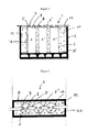
- the Figure 1 shows a battery (1) including a trunk (2) for receiving at least two electrochemical generators (3, 3 ', 3'').
- the trunk may include a lid (not shown).
- the container (4) is preferably of cylindrical shape but other formats may be envisaged such as the parallelepipedal (prismatic) format.
- the container has a wall at one of its ends resting on the bottom of the trunk (5).
- the container is closed at the opposite end by a cover (6) supporting the current output terminals (7, 8).
- One of the two terminals (7) can be fixed on the outer wall of the cover and electrically connected to the cylindrical wall of the container.
- the other terminal (8) can be fixed through the cover and electrically isolated from the cover by a plastic seal.
- the Figure 2 shows that the generator (3 ') is connected to the neighboring generators (3 and 3'') via metal bars (9, 9') which connect each current output terminal of the generator to the current output terminal of opposite polarity of the neighboring generator.
- the container of each generator comprises a side wall (12) whose free surface, that is to say without contact with the inner wall of the box, is covered with rigid fireproof plastic foam (10) with porosity closed.
- the foam covers the wall for a length of at least 25% of the height of the container.
- the foam covers the free surface of the side wall of the container over a length of at least 50% of the height of the container, more preferably at least 75% of the height of the container, more preferably at least 90% of the surface of the container.
- the plastic foam covers the side wall of the container of each electrochemical generator over the entire height of the container. In this case, any short-circuit by contact between two generators is avoided.
- This embodiment provides excellent thermal insulation and a better barrier effect against the propagation of hot gases to the generator (s) neighbor (s).
- the fireproof plastic foam also fills the space between the inner wall of the trunk (11) and the side wall (12) of the container (4) of each electrochemical generator.
- the foam (10) covers the side wall (12) of the container (4) only on its lower part, that is to say the part of the container between the mid-height of the container and the end of the container resting on the bottom (5) of the chest.
- This arrangement of the foam prevents the propagation of gases when they escape through the bottom of the container. It is preferred that the gases escape through the bottom of the container.
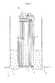
- a generator comprising such thinning is shown in FIG. Figure 5 .
- This thinning constitutes a zone of weakening of the bottom wall of the container (14) which tears in case of overpressure inside the container (4) and causes the release of gases present in This thinning constitutes a safety device making it possible to prevent the internal pressure of the container from exceeding a predetermined threshold value, Such a generator is also described in the patent. FR-B-2,873,495 .
- the container may be cylindrical in which case the thinning preferably has a circular shape whose diameter is smaller than the diameter of the container.
- the foam may cover the portion of the bottom of the container located outside the circle formed by the thinning. However, care must be taken that the thinning is not masked by the foam, which could prevent the thinning from tearing in case of overpressure inside the generator.
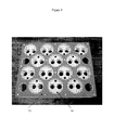
- a portion of the container sidewall (12) is covered with a closed porosity rigid fireproof foam (10) made of an electrical insulating material, while the non-foam covered portion is in contact with the inner wall of the container ( 11).
- the free surface of the container of each of the generators represents in this example approximately 50% of the total surface of the side wall of the container.
- the inner wall of the trunk matches the shape of the containers.
- the trunk is preferably made of plastic. It can be manufactured by molding which allows to modify the shape of the inner wall depending on the format of the containers.
- illustrated containers (4) Figure 6 are of cylindrical shape and the inner wall of the trunk has recesses in the form of half tubes intended to come in coincidence with the cylindrical side wall of the container of each of the generators.
- the presence of foam between two neighboring generators makes it possible to isolate one of the generators with respect to the other. In case of failure of one of the generators, the gases do not propagate to the neighboring generator.
- the inner wall of the box conforming to the shape of the containers makes it possible to fix the position of each generator and immobilize it in the box.
- the foam covers about 50% of the free surface of the side wall of the container, but other percentages of recovery are possible such as 25% to 75%, 40% to 60%, or 45% to 55%. % of the total area of the side wall of the container.
- a conventional battery box contains (empty) air volumes that vary according to the external pressure.
- pressure variations cause inflation and deflation of the trunk.
- an expandable foam in the battery facilitates its filling with a resin, which flows only by gravity, which creates bubbles and causes problems of filling.
- the use of an expandable foam facilitates its filling because the swelling pressure pushes the foam in all the cavities and crevices of the geometry to be filled. Moreover, this method makes it possible to fill all the geometries, which does not allow the method of the prefabricated blocks.
- Polyurethane, epoxy, polyethylene, silicones, melamine, polyester, formophenol and polystyrene, or a mixture thereof, polyurethane and the polyurethane / polyurethane blend can be used as foam material. epoxy being preferred.
- the thermal conductivity of the foam varies between 0.02 and 1 W / mK.
- Polyurethane is produced by reacting a diisocyanate with a hydrogen donor compound.
- Hydrogen donor compounds include water, alcohols, amines and ureas.
- Hydrochlorofluorocarbons HCFCs
- hydrofluorocarbons HFCs
- hydrocarbons HC
- CFCs chlorofluorocarbon compounds
- HFCs hydrofluorocarbons
- CH 2 FCF 3 HFC-134a
- CHF 2 CH 3 HFC-152a
- CH 3 CH 2 CHF 2 HFC-245fa
- CH 3 CH 2 CF 2 CH 3 HFC-365 mfc
- HC hydrocarbons
- iso-butane C 4 H 10 iso-pentane C 5 H 12
- n-pentane CH 3 CH 2 CHF 2 cyclo-pentane (CH 2 ) 5 .
- the use of hydrocarbons requires special precautions because of their high flammability. We can refer to the pages 131-134 of the 2002 edition of "The polyurethanes book” published by John Wiley and Sons .
- the rigid polyurethane foam may be prepared by mixing methylene diphenyl diisocyanate (MDI) or toluene diisocyananate (TDI) with a polyol, a foaming agent among those mentioned above, a flame retardant optionally a catalyst and water.
- a crosslinking agent such as triethanolamine or glycerin may be used to improve the rigidity of the foam.
- Most rigid polyurethane foams are characterized by closed-type cells (closed porosity).
- the percentage of closed cells is generally between 90 and 95%. Closed-type cells can be obtained when the cell wall remains intact during the foam-forming step. The wall is not destroyed by the pressure of gas expanding in the cell.
- the increase in temperature in the reaction mixture plays a decisive role in increasing the internal pressure of the cell.
- the expansion of the resin by the physical route as described above makes it possible to cool the reaction mixture by evaporation of the low-boiling point liquid.
- the increase in pressure therefore occurs at a time when the wall of the cells has become rigid.
- the use of the chemical route leads to a higher temperature of the reaction mixture. A rapid increase in temperature and pressure that can lead to destruction of the cell wall.
- the formation of rigid polyurethane foam is described in more detail on pages 248-251 of the second edition of the book "Polyurethane Handbook" published by Hanser Gardner .
- the flame retardant incorporated into the foam has the role of reducing the amount of flames and products of combustion. It has a latent heat of high transformation. It may be selected from the group consisting of trichloropropyl phosphate (TCPP), triethyl phosphate (PET), diethyl diethyl phosphate (DEPP), diethyl phosphonate bis (2-hydroxyethyl) amino methyl, phthalic anhydride bromo, dibromonéopentyl glycol, brominated polyether polyol, melamine, aluminum trihydrate, ammonium polyphosphate and encapsulated red phosphorus.
- TCPP trichloropropyl phosphate
- PET triethyl phosphate
- DEPP diethyl diethyl phosphate
- diethyl phosphonate bis (2-hydroxyethyl) amino methyl phthalic anhydride bromo, dibromonéopentyl glycol, brominated polyether poly
- a preferred flame retardant is trichloropropyl phosphate (TCPP) because it contains a significant amount of phosphorus and chlorine. It is in the form of a low viscosity liquid. It is easy to use.
- the brominated polyether polyol and the brominated phthalic anhydride contain a large amount of bromine.
- Triethyl phosphate (PET) and diethyl diethyl phosphate (DEEP) are preferred when the use of halogens is prohibited.
- the flame retardant is typically from 3 to 10 percent of the plastic foam.
- the rigid flame retardant foam may also contain fillers such as aluminum trihydrate, calcium carbonate, barium sulfate, glass fibers, carbon fibers, melamine, carbon black, silicon oxide.
- the invention can also be implemented using an epoxy foam made from an epoxy resin.
- the epoxy resin can be obtained by mixing epichlorohydrin with bisphenol A.
- the foaming agent can be air or a low boiling compound, for example pentane.
- the foaming agent is added in an amount of between 5 and 30% by weight of the epoxy resin. It is also possible to use compounds such as sodium bicarbonate and calcium carbonate which in the presence of acid release carbon dioxide.
- the invention can also be implemented using a polystyrene foam.
- Butane, pentane, hexane and heptane can be used as the foaming agent. It is also possible to use air, carbon dioxide, nitrogen, helium, methane, argon and neon.
- Polystyrene is dissolved by certain aromatic hydrocarbons, such as benzene, toluene, xylene and ethylbenzene, and by certain chlorinated aliphatic hydrocarbons such as methylene chloride, chloroform and carbon tetrachloride. These compounds can not therefore be used as foaming agents.
- At least one elastomer seal held for example with an adhesive against the surface of a flange 16, which is in contact with the bottom of the generator container or with the lid of the generators.
- the flange is a template that helps to keep in place the plurality of electrochemical generators by the presence of recesses 76.
- These recesses fit with (or are adapted to receive) a portion of the container surface such as the bottom of the container. or a lid for closing the container.
- the recesses were made to fit either the shape of the lid of the container or the shape of the bottom of the container.
- the elastomer seal has a plurality of openings 75 whose edge coincides with the limit of a recess ( Figure 8 ).
- the surface of the opening is smaller than the area defined by the limit of the recess to allow a good seal between the container and the elastomer seal.
- the elastomer seal due to its high deformation capacity, makes it possible to fill any gaps within a mechanical assembly.
- the assembly comprising the various elements constitutes a closed volume in which the foam is injected.
- the spacer 73 is an element making it possible to fill the empty space between the electrochemical generators. It helps to strengthen the rigidity of the battery.
- the elastomer seal attached to a flange generates a protruding lip flange that comes into contact with the trunk and ensures the absence of play, illustrated by the sealing zone 101 of the Figure 10 , between the pack and the trunk, this game being capable of generating foam leaks (the dimensions (length and width) of the seal are a few millimeters larger than those of the flange).
- FIG. 9 is a diagram showing the introduction of the pack 91 in the trunk 2.
- the generators used are of the lithium type, preferably of the lithium-ion type.
- Lithium polymer generators or liquid cathode lithium generators such as Li / SO 2 , Li / SOCl 2 , Li / MnO 2 Li / CF x , Li / MnO 2 + CF x or LiSO 2 Cl 2 can also be used. used.
Landscapes
- Chemical & Material Sciences (AREA)
- Chemical Kinetics & Catalysis (AREA)
- Electrochemistry (AREA)
- General Chemical & Material Sciences (AREA)
- Engineering & Computer Science (AREA)
- Manufacturing & Machinery (AREA)
- Battery Mounting, Suspending (AREA)
- Secondary Cells (AREA)
- Sealing Battery Cases Or Jackets (AREA)
- Primary Cells (AREA)
- Gas Exhaust Devices For Batteries (AREA)
Applications Claiming Priority (1)
| Application Number | Priority Date | Filing Date | Title |
|---|---|---|---|
| FR1055366A FR2962261B1 (fr) | 2010-07-02 | 2010-07-02 | Batterie de generateurs electrochimiques comprenant une mousse comme materiau de remplissage entre generateurs |
Publications (2)
| Publication Number | Publication Date |
|---|---|
| EP2403050A1 true EP2403050A1 (de) | 2012-01-04 |
| EP2403050B1 EP2403050B1 (de) | 2018-07-18 |
Family
ID=43470523
Family Applications (1)
| Application Number | Title | Priority Date | Filing Date |
|---|---|---|---|
| EP11169991.4A Active EP2403050B1 (de) | 2010-07-02 | 2011-06-15 | Batterie von elektrochemischen Generatoren, die einen Schaumstoff als Füllmaterial zwischen Generatoren umfasst |
Country Status (5)
| Country | Link |
|---|---|
| US (1) | US20120003508A1 (de) |
| EP (1) | EP2403050B1 (de) |
| CA (1) | CA2743528C (de) |
| ES (1) | ES2688483T3 (de) |
| FR (1) | FR2962261B1 (de) |
Cited By (15)
| Publication number | Priority date | Publication date | Assignee | Title |
|---|---|---|---|---|
| WO2013058974A1 (en) * | 2011-10-18 | 2013-04-25 | Johnson Controls Technology Llc | Electrochemical cell having a safety device |
| CN103311471A (zh) * | 2012-03-14 | 2013-09-18 | 株式会社东芝 | 二次电池装置 |
| FR2992775A1 (fr) * | 2012-07-02 | 2014-01-03 | Valeo Equip Electr Moteur | Stockeur d'energie electrique et procede de fabrication correspondant |
| WO2014131875A1 (fr) * | 2013-03-01 | 2014-09-04 | Saft | Dispositif de securite pour une batterie de generateurs electrochimiques au lithium |
| FR3002815A1 (fr) * | 2013-03-01 | 2014-09-05 | Accumulateurs Fixes | Dispositif de securite pour une batterie de generateurs electrochimiques au lithium |
| WO2015086670A3 (de) * | 2013-12-10 | 2015-09-03 | Akasol Gmbh | Batteriemodul |
| US9412985B2 (en) | 2013-03-15 | 2016-08-09 | Saft | Safety device for a lithium electrochemical generator battery |
| FR3042093A1 (fr) * | 2015-10-05 | 2017-04-07 | Blue Solutions | Module de stockage d'energie electrique et son procede de fabrication |
| WO2017178634A1 (fr) | 2016-04-14 | 2017-10-19 | Saft | Assemblage d'elements electrochimiques par un procede de fabrication additive |
| US9853263B2 (en) | 2014-11-10 | 2017-12-26 | Ford Global Technologies, Llc | Battery assembly including structural foamed materials |
| WO2019077245A1 (fr) * | 2017-10-17 | 2019-04-25 | Blue Solutions | Module de stockage d'énergie électrique à résistance de fuite intégrée |
| US10355330B2 (en) | 2016-08-31 | 2019-07-16 | Akasol Gmbh | Battery module assembly and cooling plate for use in a battery module assembly |
| CN110957500A (zh) * | 2019-11-04 | 2020-04-03 | 上海空间电源研究所 | 一种热电池用新型外部隔热装置 |
| WO2022155056A1 (en) * | 2021-01-15 | 2022-07-21 | Rogers Corporation | Thermally insulating multilayer sheet, method of manufacture, and articles using the same |
| FR3121285A1 (fr) | 2021-03-26 | 2022-09-30 | Saft | Matériau de calage d’éléments électrochimiques dans une batterie |
Families Citing this family (79)
| Publication number | Priority date | Publication date | Assignee | Title |
|---|---|---|---|---|
| DE102011102765A1 (de) * | 2011-05-28 | 2012-11-29 | Audi Ag | Batterie für ein Fahrzeug und Verfahren zum Fertigen einer Batterie |
| ITBO20120056A1 (it) * | 2012-02-07 | 2013-08-08 | Ferrari Spa | Sistema di accumulo di energia elettrica per un veicolo con propulsione elettrica e presentante una struttura priva di linee di resistenza longitudinali o trasversali |
| ITBO20120057A1 (it) | 2012-02-07 | 2013-08-08 | Ferrari Spa | Sistema di accumulo di energia elettrica per un veicolo con propulsione elettrica e presentante batteria chimiche cilindriche annegate in una matrice di supporto |
| ITBO20120183A1 (it) * | 2012-04-06 | 2013-10-07 | Ferrari Spa | Sistema di accumulo di energia elettrica per un veicolo con propulsione elettrica e presentante batteria chimiche cilindriche collegate tra loro in parallelo e serie mediante elementi di collegamento rigidi conformati ad "u" |
| ITBO20120184A1 (it) * | 2012-04-06 | 2013-10-07 | Ferrari Spa | Sistema di accumulo di energia elettrica per un veicolo con propulsione elettrica e presentante batterie chimiche cilindriche inserite in una matrice di supporto plastica |
| US10637022B2 (en) | 2012-10-11 | 2020-04-28 | Cadenza Innovation, Inc. | Lithium ion battery |
| KR20170062555A (ko) | 2012-10-11 | 2017-06-07 | 카덴차 이노베이션, 인크 | 리튬 이온 배터리 |
| US10790489B2 (en) | 2012-10-11 | 2020-09-29 | Cadenza Innovation, Inc. | Lithium ion battery |
| JP6286438B2 (ja) | 2012-10-16 | 2018-02-28 | アンブリ・インコーポレイテッド | 電気化学エネルギー蓄積デバイスおよびハウジング |
| US9735450B2 (en) | 2012-10-18 | 2017-08-15 | Ambri Inc. | Electrochemical energy storage devices |
| US9312522B2 (en) | 2012-10-18 | 2016-04-12 | Ambri Inc. | Electrochemical energy storage devices |
| US9520618B2 (en) | 2013-02-12 | 2016-12-13 | Ambri Inc. | Electrochemical energy storage devices |
| US11387497B2 (en) | 2012-10-18 | 2022-07-12 | Ambri Inc. | Electrochemical energy storage devices |
| US11211641B2 (en) | 2012-10-18 | 2021-12-28 | Ambri Inc. | Electrochemical energy storage devices |
| US11721841B2 (en) | 2012-10-18 | 2023-08-08 | Ambri Inc. | Electrochemical energy storage devices |
| US10541451B2 (en) | 2012-10-18 | 2020-01-21 | Ambri Inc. | Electrochemical energy storage devices |
| US20140154539A1 (en) * | 2012-12-05 | 2014-06-05 | Caterpillar Inc. | Module for securing energy storage cells |
| DE102013201052A1 (de) * | 2013-01-23 | 2014-07-24 | Robert Bosch Gmbh | Verfahren zum Herstellen eines Energiespeichers |
| US10270139B1 (en) | 2013-03-14 | 2019-04-23 | Ambri Inc. | Systems and methods for recycling electrochemical energy storage devices |
| US9502737B2 (en) | 2013-05-23 | 2016-11-22 | Ambri Inc. | Voltage-enhanced energy storage devices |
| US9991481B2 (en) * | 2013-05-29 | 2018-06-05 | Inoac Corporation | Thermal insulating cover |
| EP3058605B1 (de) | 2013-10-16 | 2023-12-06 | Ambri Inc. | Dichtungen für vorrichtungen aus reaktivem hochtemperaturmaterial |
| DE102013224738A1 (de) * | 2013-12-03 | 2015-06-03 | Robert Bosch Gmbh | Schutz von Batteriezellen vor einem Durchgehen |
| DE102014002165B3 (de) * | 2014-02-19 | 2015-01-22 | Lisa Dräxlmaier GmbH | Verfahren zur Fixierung von Rundzellen mittels komprimierter Zellenfixierung und Zellenblock |
| DE102014206868B4 (de) * | 2014-04-09 | 2023-08-24 | Frederic Dietze | Gehäuse für eine Energiespeichervorrichtung, Energiespeichervorrichtung mit einem derartigen Gehäuse und Verfahren zu deren Herstellung |
| EP3131645B1 (de) * | 2014-04-13 | 2019-01-30 | Phinergy Ltd. | Sicherheitsverfahren und system für flüssigelektrolytbatterie |
| EP3146574A1 (de) * | 2014-05-21 | 2017-03-29 | Thermal Ceramics, Inc. | Passive wärmedämmstoffe |
| CN104218194B (zh) * | 2014-07-30 | 2018-05-04 | 浙江超威创元实业有限公司 | 一种具有防火防爆装置的锂电池及应用该电池的电动车 |
| US9786883B2 (en) * | 2014-08-27 | 2017-10-10 | X Development Llc | Battery containment mesh |
| US10181800B1 (en) | 2015-03-02 | 2019-01-15 | Ambri Inc. | Power conversion systems for energy storage devices |
| WO2016141354A2 (en) | 2015-03-05 | 2016-09-09 | Ambri Inc. | Ceramic materials and seals for high temperature reactive material devices |
| US10707526B2 (en) | 2015-03-27 | 2020-07-07 | New Dominion Enterprises Inc. | All-inorganic solvents for electrolytes |
| US9893385B1 (en) | 2015-04-23 | 2018-02-13 | Ambri Inc. | Battery management systems for energy storage devices |
| WO2017059419A1 (en) | 2015-10-02 | 2017-04-06 | Alcoa Inc. | Energy storage device and related methods |
| DE102016202024A1 (de) * | 2016-02-10 | 2017-08-10 | Volkswagen Aktiengesellschaft | Batteriebaugruppe sowie Verfahren zur Herstellung derselben |
| US10873111B2 (en) * | 2016-08-09 | 2020-12-22 | Wisk Aero Llc | Battery with compression and prevention of thermal runaway propagation features |
| US11929466B2 (en) | 2016-09-07 | 2024-03-12 | Ambri Inc. | Electrochemical energy storage devices |
| US10707531B1 (en) | 2016-09-27 | 2020-07-07 | New Dominion Enterprises Inc. | All-inorganic solvents for electrolytes |
| JP6845343B2 (ja) | 2017-02-08 | 2021-03-17 | エルケム・シリコーンズ・ユーエスエイ・コーポレーションElkem Silicones Usa Corp. | 温度管理の改善された二次電池パック |
| US10829609B2 (en) | 2017-02-08 | 2020-11-10 | Elkem Silicones USA Corp. | Silicone rubber syntactic foam |
| CN110731027A (zh) | 2017-04-07 | 2020-01-24 | 安保瑞公司 | 具有固体金属阴极的熔盐电池 |
| WO2019105570A1 (de) * | 2017-12-01 | 2019-06-06 | Hoppecke Batterien Gmbh & Co. Kg | Batteriegehäuse |
| EP3496180A1 (de) * | 2017-12-08 | 2019-06-12 | Atnom S.R.L. | Ultraleichte feuerfeste batterieanordnung mit passiver kühlung und optionaler aktiver temperatursteuerung |
| DE102017223438A1 (de) * | 2017-12-20 | 2019-06-27 | Lion Smart Gmbh | Batterievorrichtung für ein elektrisch angetriebenes Fahrzeug |
| US10644282B2 (en) | 2018-01-23 | 2020-05-05 | Nio Usa, Inc. | Staggered battery cell array with two-dimensional inline terminal edges |
| JP7258896B2 (ja) * | 2018-02-16 | 2023-04-17 | エイチ.ビー.フラー カンパニー | 電気セル用ポッティング化合物及び作製する方法 |
| US10892465B2 (en) | 2018-03-22 | 2021-01-12 | Nio Usa, Inc. | Battery cell cover including terminal short isolation feature |
| US10741808B2 (en) | 2018-03-15 | 2020-08-11 | Nio Usa, Inc. | Unified battery module with integrated battery cell structural support |
| US10741889B2 (en) | 2018-03-22 | 2020-08-11 | Nio Usa, Inc. | Multiple-zone thermocouple battery module temperature monitoring system |
| US10707471B2 (en) | 2018-03-22 | 2020-07-07 | Nio Usa, Inc. | Single side cell-to-cell battery module interconnection |
| US10784486B2 (en) | 2018-02-20 | 2020-09-22 | Nio Usa, Inc. | Uniform current density tapered busbar |
| DE102018110269A1 (de) * | 2018-04-27 | 2019-10-31 | Airbus Operations Gmbh | Batteriehaltevorrichtung sowie Flugzeug mit einer derartigen Batteriehaltevorrichtung |
| DE102018206800A1 (de) * | 2018-05-03 | 2019-11-07 | Audi Ag | System zum Herstellen einer Batterieanordnung |
| US10756398B2 (en) | 2018-06-22 | 2020-08-25 | Wisk Aero Llc | Capacitance reducing battery submodule with thermal runaway propagation prevention and containment features |
| EP3830883A4 (de) | 2018-07-30 | 2022-05-18 | Cadenza Innovation, Inc. | Gehäuse für wiederaufladbare batterien |
| US10593920B2 (en) | 2018-08-13 | 2020-03-17 | Wisk Aero Llc | Capacitance reduction in battery systems |
| DE102018214529A1 (de) * | 2018-08-28 | 2020-03-05 | Mahle International Gmbh | Akkumulatoranordnung |
| DE102018214528A1 (de) * | 2018-08-28 | 2020-03-05 | Mahle International Gmbh | Akkumulatoranordnung |
| DE102018217319A1 (de) * | 2018-10-10 | 2020-04-16 | Mahle International Gmbh | Akkumulator |
| US11367893B2 (en) | 2018-11-07 | 2022-06-21 | The Boeing Company | Multifunctional battery packaging and insulation |
| DE102019206284B4 (de) * | 2019-05-02 | 2022-11-03 | Psa Automobiles Sa | Batterieeinheit und Wärmeleitelement für ein Kraftfahrzeug |
| DE102019120708A1 (de) * | 2019-07-31 | 2021-02-04 | Bayerische Motoren Werke Aktiengesellschaft | Energiespeicher für ein Kraftfahrzeug mit mindestens einer flammenverzögernden Schicht |
| KR20210044534A (ko) * | 2019-10-15 | 2021-04-23 | 주식회사 엘지화학 | 배터리 팩 |
| DE102019216606A1 (de) * | 2019-10-29 | 2021-04-29 | Thyssenkrupp Ag | Batteriemodul |
| KR20210061829A (ko) * | 2019-11-20 | 2021-05-28 | 주식회사 엘지에너지솔루션 | 배터리 모듈, 이러한 배터리 모듈을 포함하는 배터리 팩 및 자동차 |
| FR3104323B1 (fr) | 2019-12-06 | 2021-11-05 | Accumulateurs Fixes | Dispositif de deconnexion comprenant un element thermo-activable |
| JP2023501735A (ja) * | 2020-06-16 | 2023-01-18 | エルジー エナジー ソリューション リミテッド | バッテリーパック、それを含む電子デバイス及び自動車 |
| US11349147B2 (en) | 2020-06-26 | 2022-05-31 | Cadenza Innovation, Inc. | Battery systems |
| DE102020005288A1 (de) | 2020-08-28 | 2022-03-03 | Hexion GmbH | Schaumharzzusammensetzung |
| EP4222808A1 (de) * | 2020-10-01 | 2023-08-09 | BAE Systems Controls Inc. | Abschwächung der ausbreitung von thermischem durchgehen in lithium-ionen-batteriepacks |
| JP2023523204A (ja) * | 2020-10-12 | 2023-06-02 | エルジー エナジー ソリューション リミテッド | バッテリーモジュール、バッテリーパック、及び自動車 |
| TW202320393A (zh) | 2021-08-13 | 2023-05-16 | 美商埃肯矽樹脂美國股份有限公司 | 具有經改良熱管理之次要電池組 |
| US20230136731A1 (en) * | 2021-09-15 | 2023-05-04 | Beta Air, Llc | Battery system and method of an electric aircraft with spring conductors |
| TWI797874B (zh) * | 2021-12-07 | 2023-04-01 | 淡江大學學校財團法人淡江大學 | 電池散熱、剛性與阻燃一體化熱管理模組 |
| DE102022103618A1 (de) | 2022-02-16 | 2023-08-17 | Lisa Dräxlmaier GmbH | Batteriemodul und verfahren zum herstellen eines batteriemoduls |
| KR20230130466A (ko) * | 2022-03-03 | 2023-09-12 | 주식회사 엘지에너지솔루션 | 전지 셀 가압지그 |
| WO2024052451A1 (en) | 2022-09-09 | 2024-03-14 | Basf Se | Battery potting material with improved adhesion to metal |
| KR20240043384A (ko) * | 2022-09-27 | 2024-04-03 | 주식회사 엘지에너지솔루션 | 연쇄 발화 방지용 배터리모듈 및 이의 제조 방법 |
| DE102022125203A1 (de) * | 2022-09-29 | 2024-04-04 | Bayerische Motoren Werke Aktiengesellschaft | Energiespeicherzelle, Energiespeicher, Kraftfahrzeug und Verfahren zum Herstellen einer Energiespeicherzelle |
Citations (28)
| Publication number | Priority date | Publication date | Assignee | Title |
|---|---|---|---|---|
| GB938359A (en) | 1961-09-01 | 1963-10-02 | Steels & Busks Ltd | Riveting and rivet setting machines |
| US3269865A (en) | 1963-05-20 | 1966-08-30 | Ford Motor Co | Battery elements anchored with urethane foam |
| CA767207A (en) | 1967-09-12 | Ford Motor Company Of Canada | Battery elements anchored with urethane foam | |
| CA1064575A (en) | 1975-07-09 | 1979-10-16 | W.R. Grace And Co. | Battery enveloping with foam |
| US4418127A (en) | 1981-11-23 | 1983-11-29 | The United States Of America As Represented By The Secretary Of The Air Force | Battery cell module |
| JPS62211854A (ja) | 1986-03-11 | 1987-09-17 | Hitachi Maxell Ltd | リチウム電池 |
| JPH042043A (ja) | 1990-04-18 | 1992-01-07 | Matsushita Electric Ind Co Ltd | 電池 |
| US5352454A (en) | 1991-06-10 | 1994-10-04 | Dyco Associates, Inc. | Anti-chewing and anti-cribbing composition |
| EP0676818A1 (de) | 1994-04-06 | 1995-10-11 | Daniel Longchamp | Batterieschutz |
| JPH07296786A (ja) | 1994-04-22 | 1995-11-10 | Matsushita Electric Ind Co Ltd | 電池ケース |
| JPH09120812A (ja) | 1995-10-27 | 1997-05-06 | Fuji Elelctrochem Co Ltd | 集合電池 |
| JPH11210982A (ja) | 1998-01-19 | 1999-08-06 | Yoshie Kanai | 断熱保温材及びこれを用いたバッテリー機能低下防止装置 |
| JP2002231297A (ja) | 2001-01-29 | 2002-08-16 | Japan Storage Battery Co Ltd | 組電池 |
| KR20040105338A (ko) | 2003-06-07 | 2004-12-16 | 주식회사 코캄엔지니어링 | 리튬 이차 전지 |
| DE202005010708U1 (de) | 2005-07-06 | 2005-09-08 | FRÖTEK Kunststofftechnik GmbH | Gehäuse für Akkumulatorbatterien |
| FR2873495B1 (fr) | 2004-07-23 | 2006-10-20 | Accumulateurs Fixes | Dispositif de securite pour accumulateur etanche |
| JP2006324014A (ja) | 2005-05-17 | 2006-11-30 | Toyo Seikan Kaisha Ltd | 電池用シーリングコンパウンド及び電池用容器の巻締め部形成方法 |
| JP2006339017A (ja) | 2005-06-01 | 2006-12-14 | Sanyo Electric Co Ltd | 組電池 |
| US20070259258A1 (en) | 2006-05-04 | 2007-11-08 | Derrick Scott Buck | Battery assembly with temperature control device |
| CN101106185A (zh) | 2007-09-04 | 2008-01-16 | 北京中润恒动电池有限公司 | 高安全性锂离子动力电池及其装配方法 |
| US20080090137A1 (en) * | 2006-10-13 | 2008-04-17 | Derrick Scott Buck | Battery pack with integral cooling and bussing devices |
| DE102007010751A1 (de) * | 2007-02-27 | 2008-08-28 | Daimler Ag | Batteriegehäuse |
| DE102007063174A1 (de) * | 2007-12-20 | 2009-06-25 | Daimler Ag | Batterie mit mehreren parallel und/oder seriell miteinander verschalteten Einzelzellen und einer Wärmeleitplatte zum Temperieren der Batterie |
| DE102007063194A1 (de) * | 2007-12-20 | 2009-06-25 | Daimler Ag | Zellverbund sowie Verfahren zur Herstellung eines Zellverbundes |
| WO2010040363A2 (de) * | 2008-10-07 | 2010-04-15 | Fev Motorentechnik Gmbh | Lithium-ionen-batterie |
| DE102008059956A1 (de) * | 2008-12-02 | 2010-06-10 | Daimler Ag | Batterie, insbesondere Fahrzeugbatterie |
| DE102008059971A1 (de) * | 2008-12-02 | 2010-06-10 | Daimler Ag | Batterie, insbesondere Fahrzeugbatterie und Verfahren zu dessen Herstellung |
| DE202010002352U1 (de) * | 2010-01-08 | 2010-07-22 | Sensor-Technik Wiedemann Gmbh | Elektrochemischer Energiespeicher |
Family Cites Families (6)
| Publication number | Priority date | Publication date | Assignee | Title |
|---|---|---|---|---|
| US5283137A (en) * | 1991-04-29 | 1994-02-01 | Optima Batteries, Inc. | Cover assembly for rechargeable battery |
| US20070218353A1 (en) * | 2005-05-12 | 2007-09-20 | Straubel Jeffrey B | System and method for inhibiting the propagation of an exothermic event |
| WO2009085191A2 (en) * | 2007-12-21 | 2009-07-09 | Cabot Corporation | Syntactic foam compositions, pipelines insulated with same, and method |
| JP5386155B2 (ja) * | 2008-11-28 | 2014-01-15 | 株式会社日立製作所 | 蓄電装置 |
| FR2939969B1 (fr) * | 2008-12-16 | 2010-12-10 | Saft Groupe Sa | Systeme de maintien d'accumulateurs electrochimiques |
| JP5509684B2 (ja) * | 2009-06-03 | 2014-06-04 | ソニー株式会社 | 電池パック |
-
2010
- 2010-07-02 FR FR1055366A patent/FR2962261B1/fr active Active
-
2011
- 2011-06-15 CA CA2743528A patent/CA2743528C/fr active Active
- 2011-06-15 ES ES11169991.4T patent/ES2688483T3/es active Active
- 2011-06-15 EP EP11169991.4A patent/EP2403050B1/de active Active
- 2011-06-23 US US13/167,521 patent/US20120003508A1/en not_active Abandoned
Patent Citations (28)
| Publication number | Priority date | Publication date | Assignee | Title |
|---|---|---|---|---|
| CA767207A (en) | 1967-09-12 | Ford Motor Company Of Canada | Battery elements anchored with urethane foam | |
| GB938359A (en) | 1961-09-01 | 1963-10-02 | Steels & Busks Ltd | Riveting and rivet setting machines |
| US3269865A (en) | 1963-05-20 | 1966-08-30 | Ford Motor Co | Battery elements anchored with urethane foam |
| CA1064575A (en) | 1975-07-09 | 1979-10-16 | W.R. Grace And Co. | Battery enveloping with foam |
| US4418127A (en) | 1981-11-23 | 1983-11-29 | The United States Of America As Represented By The Secretary Of The Air Force | Battery cell module |
| JPS62211854A (ja) | 1986-03-11 | 1987-09-17 | Hitachi Maxell Ltd | リチウム電池 |
| JPH042043A (ja) | 1990-04-18 | 1992-01-07 | Matsushita Electric Ind Co Ltd | 電池 |
| US5352454A (en) | 1991-06-10 | 1994-10-04 | Dyco Associates, Inc. | Anti-chewing and anti-cribbing composition |
| EP0676818A1 (de) | 1994-04-06 | 1995-10-11 | Daniel Longchamp | Batterieschutz |
| JPH07296786A (ja) | 1994-04-22 | 1995-11-10 | Matsushita Electric Ind Co Ltd | 電池ケース |
| JPH09120812A (ja) | 1995-10-27 | 1997-05-06 | Fuji Elelctrochem Co Ltd | 集合電池 |
| JPH11210982A (ja) | 1998-01-19 | 1999-08-06 | Yoshie Kanai | 断熱保温材及びこれを用いたバッテリー機能低下防止装置 |
| JP2002231297A (ja) | 2001-01-29 | 2002-08-16 | Japan Storage Battery Co Ltd | 組電池 |
| KR20040105338A (ko) | 2003-06-07 | 2004-12-16 | 주식회사 코캄엔지니어링 | 리튬 이차 전지 |
| FR2873495B1 (fr) | 2004-07-23 | 2006-10-20 | Accumulateurs Fixes | Dispositif de securite pour accumulateur etanche |
| JP2006324014A (ja) | 2005-05-17 | 2006-11-30 | Toyo Seikan Kaisha Ltd | 電池用シーリングコンパウンド及び電池用容器の巻締め部形成方法 |
| JP2006339017A (ja) | 2005-06-01 | 2006-12-14 | Sanyo Electric Co Ltd | 組電池 |
| DE202005010708U1 (de) | 2005-07-06 | 2005-09-08 | FRÖTEK Kunststofftechnik GmbH | Gehäuse für Akkumulatorbatterien |
| US20070259258A1 (en) | 2006-05-04 | 2007-11-08 | Derrick Scott Buck | Battery assembly with temperature control device |
| US20080090137A1 (en) * | 2006-10-13 | 2008-04-17 | Derrick Scott Buck | Battery pack with integral cooling and bussing devices |
| DE102007010751A1 (de) * | 2007-02-27 | 2008-08-28 | Daimler Ag | Batteriegehäuse |
| CN101106185A (zh) | 2007-09-04 | 2008-01-16 | 北京中润恒动电池有限公司 | 高安全性锂离子动力电池及其装配方法 |
| DE102007063174A1 (de) * | 2007-12-20 | 2009-06-25 | Daimler Ag | Batterie mit mehreren parallel und/oder seriell miteinander verschalteten Einzelzellen und einer Wärmeleitplatte zum Temperieren der Batterie |
| DE102007063194A1 (de) * | 2007-12-20 | 2009-06-25 | Daimler Ag | Zellverbund sowie Verfahren zur Herstellung eines Zellverbundes |
| WO2010040363A2 (de) * | 2008-10-07 | 2010-04-15 | Fev Motorentechnik Gmbh | Lithium-ionen-batterie |
| DE102008059956A1 (de) * | 2008-12-02 | 2010-06-10 | Daimler Ag | Batterie, insbesondere Fahrzeugbatterie |
| DE102008059971A1 (de) * | 2008-12-02 | 2010-06-10 | Daimler Ag | Batterie, insbesondere Fahrzeugbatterie und Verfahren zu dessen Herstellung |
| DE202010002352U1 (de) * | 2010-01-08 | 2010-07-22 | Sensor-Technik Wiedemann Gmbh | Elektrochemischer Energiespeicher |
Non-Patent Citations (5)
| Title |
|---|
| "Polyurethane Handbook", HANSER GARDNER, pages: 111 - 113 |
| "Polyurethane Handbook", HANSER GARDNER, pages: 248 - 251 |
| "The polyurethanes book", 2002, JOHN WILEY AND SONS, LTD, pages: 160 - 162 |
| "The polyurethanes book", 2002, JOHN WILEY AND SONS, pages: 113 - 122 |
| "The polyurethanes book", 2002, JOHN WILEY AND SONS, pages: 131 - 134 |
Cited By (23)
| Publication number | Priority date | Publication date | Assignee | Title |
|---|---|---|---|---|
| US9196920B2 (en) | 2011-10-18 | 2015-11-24 | Johnson Controls Technology Llc | Electrochemical cell having a safety device |
| WO2013058974A1 (en) * | 2011-10-18 | 2013-04-25 | Johnson Controls Technology Llc | Electrochemical cell having a safety device |
| CN103311471A (zh) * | 2012-03-14 | 2013-09-18 | 株式会社东芝 | 二次电池装置 |
| CN103311471B (zh) * | 2012-03-14 | 2016-08-03 | 株式会社东芝 | 二次电池装置 |
| FR2992775A1 (fr) * | 2012-07-02 | 2014-01-03 | Valeo Equip Electr Moteur | Stockeur d'energie electrique et procede de fabrication correspondant |
| CN105051937A (zh) * | 2013-03-01 | 2015-11-11 | Saft公司 | 锂电化学发电装置式电池的安全装置 |
| FR3002815A1 (fr) * | 2013-03-01 | 2014-09-05 | Accumulateurs Fixes | Dispositif de securite pour une batterie de generateurs electrochimiques au lithium |
| WO2014131875A1 (fr) * | 2013-03-01 | 2014-09-04 | Saft | Dispositif de securite pour une batterie de generateurs electrochimiques au lithium |
| US9412985B2 (en) | 2013-03-15 | 2016-08-09 | Saft | Safety device for a lithium electrochemical generator battery |
| WO2015086670A3 (de) * | 2013-12-10 | 2015-09-03 | Akasol Gmbh | Batteriemodul |
| US11211646B2 (en) | 2013-12-10 | 2021-12-28 | Akasol Ag | Battery module |
| US9853263B2 (en) | 2014-11-10 | 2017-12-26 | Ford Global Technologies, Llc | Battery assembly including structural foamed materials |
| US11264667B2 (en) | 2014-11-10 | 2022-03-01 | Ford Global Technologies, Llc | Battery assembly including structural foamed materials |
| FR3042093A1 (fr) * | 2015-10-05 | 2017-04-07 | Blue Solutions | Module de stockage d'energie electrique et son procede de fabrication |
| CN108140770A (zh) * | 2015-10-05 | 2018-06-08 | 布鲁技术公司 | 电能存储模块以及用于生产电能存储模块的方法 |
| WO2017060284A1 (fr) | 2015-10-05 | 2017-04-13 | Blue Solutions | Module de stockage d'énergie électrique et son procédé de fabrication |
| WO2017178634A1 (fr) | 2016-04-14 | 2017-10-19 | Saft | Assemblage d'elements electrochimiques par un procede de fabrication additive |
| US10355330B2 (en) | 2016-08-31 | 2019-07-16 | Akasol Gmbh | Battery module assembly and cooling plate for use in a battery module assembly |
| WO2019077245A1 (fr) * | 2017-10-17 | 2019-04-25 | Blue Solutions | Module de stockage d'énergie électrique à résistance de fuite intégrée |
| CN110957500A (zh) * | 2019-11-04 | 2020-04-03 | 上海空间电源研究所 | 一种热电池用新型外部隔热装置 |
| WO2022155056A1 (en) * | 2021-01-15 | 2022-07-21 | Rogers Corporation | Thermally insulating multilayer sheet, method of manufacture, and articles using the same |
| FR3121285A1 (fr) | 2021-03-26 | 2022-09-30 | Saft | Matériau de calage d’éléments électrochimiques dans une batterie |
| EP4071908A1 (de) | 2021-03-26 | 2022-10-12 | Saft | Material zum fixieren von elektrochemischen elementen in einer batterie |
Also Published As
| Publication number | Publication date |
|---|---|
| CA2743528C (fr) | 2018-04-10 |
| FR2962261B1 (fr) | 2013-08-02 |
| CA2743528A1 (fr) | 2012-01-02 |
| EP2403050B1 (de) | 2018-07-18 |
| US20120003508A1 (en) | 2012-01-05 |
| FR2962261A1 (fr) | 2012-01-06 |
| ES2688483T3 (es) | 2018-11-02 |
Similar Documents
| Publication | Publication Date | Title |
|---|---|---|
| EP2403050B1 (de) | Batterie von elektrochemischen Generatoren, die einen Schaumstoff als Füllmaterial zwischen Generatoren umfasst | |
| JP6674567B2 (ja) | リチウムイオンバッテリ | |
| CN103931019B (zh) | 改善安全性的电池模块和包括该电池模块的电池组 | |
| US10581043B2 (en) | Frame for portable electrical energy storage cells | |
| CN109891625B (zh) | 具有改进的安全性的电池模块和电池组 | |
| US20160254578A1 (en) | Portable electrical energy storage device with in-situ formable fluid channels | |
| JP2007200880A (ja) | 安全装置を備えた中型又は大型バッテリーパック | |
| US8920950B2 (en) | Pouch type battery cell and module having exhaust part in a region of the sealing part | |
| KR102311426B1 (ko) | 이차 전지 및 이를 포함하는 전지 모듈 | |
| KR102518866B1 (ko) | 벤팅부를 포함하는 이차전지 | |
| CN105849933A (zh) | 带有热逸溃减缓的便携式电能储存器件 | |
| KR102335202B1 (ko) | 열팽창성 층을 도입한 파우치형 이차전지 및 이의 제조방법 | |
| US9196920B2 (en) | Electrochemical cell having a safety device | |
| JP7416829B2 (ja) | バッテリーラック及びそれを含む電力貯蔵装置 | |
| KR101419570B1 (ko) | 가스 배출부를 포함하는 파우치형 리튬 이차 전지 및 그 제조방법 | |
| WO2018124231A1 (ja) | 仕切り部材、組電池及び組電池の熱伝達制御方法 | |
| EP4117093A1 (de) | Batteriepack mit struktur zur unterdrückung von thermischer diffusion | |
| CN109690820B (zh) | 包括热膨胀带的安全性提高的电池单元及其制造方法 | |
| KR100509747B1 (ko) | 리튬 이차 전지 | |
| KR101684321B1 (ko) | 열가소성 수지가 주입된 전지셀의 제조 방법 | |
| EP4117091A1 (de) | Batteriepack mit struktur zur unterdrückung von thermischer diffusion |
Legal Events
| Date | Code | Title | Description |
|---|---|---|---|
| AK | Designated contracting states |
Kind code of ref document: A1 Designated state(s): AL AT BE BG CH CY CZ DE DK EE ES FI FR GB GR HR HU IE IS IT LI LT LU LV MC MK MT NL NO PL PT RO RS SE SI SK SM TR |
|
| AX | Request for extension of the european patent |
Extension state: BA ME |
|
| PUAI | Public reference made under article 153(3) epc to a published international application that has entered the european phase |
Free format text: ORIGINAL CODE: 0009012 |
|
| 17P | Request for examination filed |
Effective date: 20120330 |
|
| 17Q | First examination report despatched |
Effective date: 20130403 |
|
| STAA | Information on the status of an ep patent application or granted ep patent |
Free format text: STATUS: EXAMINATION IS IN PROGRESS |
|
| REG | Reference to a national code |
Ref country code: DE Ref legal event code: R079 Ref document number: 602011050104 Country of ref document: DE Free format text: PREVIOUS MAIN CLASS: H01M0010500000 Ipc: H01M0002100000 |
|
| RIC1 | Information provided on ipc code assigned before grant |
Ipc: H01M 10/653 20140101ALI20171024BHEP Ipc: H01M 10/0525 20100101ALN20171024BHEP Ipc: H01M 2/02 20060101ALN20171024BHEP Ipc: H01M 2/10 20060101AFI20171024BHEP |
|
| GRAP | Despatch of communication of intention to grant a patent |
Free format text: ORIGINAL CODE: EPIDOSNIGR1 |
|
| STAA | Information on the status of an ep patent application or granted ep patent |
Free format text: STATUS: GRANT OF PATENT IS INTENDED |
|
| INTG | Intention to grant announced |
Effective date: 20180226 |
|
| GRAS | Grant fee paid |
Free format text: ORIGINAL CODE: EPIDOSNIGR3 |
|
| GRAA | (expected) grant |
Free format text: ORIGINAL CODE: 0009210 |
|
| STAA | Information on the status of an ep patent application or granted ep patent |
Free format text: STATUS: THE PATENT HAS BEEN GRANTED |
|
| AK | Designated contracting states |
Kind code of ref document: B1 Designated state(s): AL AT BE BG CH CY CZ DE DK EE ES FI FR GB GR HR HU IE IS IT LI LT LU LV MC MK MT NL NO PL PT RO RS SE SI SK SM TR |
|
| REG | Reference to a national code |
Ref country code: GB Ref legal event code: FG4D Free format text: NOT ENGLISH |
|
| REG | Reference to a national code |
Ref country code: CH Ref legal event code: EP |
|
| REG | Reference to a national code |
Ref country code: IE Ref legal event code: FG4D Free format text: LANGUAGE OF EP DOCUMENT: FRENCH |
|
| REG | Reference to a national code |
Ref country code: AT Ref legal event code: REF Ref document number: 1020303 Country of ref document: AT Kind code of ref document: T Effective date: 20180815 |
|
| REG | Reference to a national code |
Ref country code: DE Ref legal event code: R096 Ref document number: 602011050104 Country of ref document: DE |
|
| REG | Reference to a national code |
Ref country code: NL Ref legal event code: FP |
|
| REG | Reference to a national code |
Ref country code: CH Ref legal event code: NV Representative=s name: WEINMANN ZIMMERLI, CH |
|
| REG | Reference to a national code |
Ref country code: SE Ref legal event code: TRGR |
|
| REG | Reference to a national code |
Ref country code: ES Ref legal event code: FG2A Ref document number: 2688483 Country of ref document: ES Kind code of ref document: T3 Effective date: 20181102 |
|
| REG | Reference to a national code |
Ref country code: NO Ref legal event code: T2 Effective date: 20180718 |
|
| REG | Reference to a national code |
Ref country code: LT Ref legal event code: MG4D |
|
| REG | Reference to a national code |
Ref country code: CH Ref legal event code: PK Free format text: RECTIFICATIONS |
|
| REG | Reference to a national code |
Ref country code: AT Ref legal event code: MK05 Ref document number: 1020303 Country of ref document: AT Kind code of ref document: T Effective date: 20180718 |
|
| RIC2 | Information provided on ipc code assigned after grant |
Ipc: H01M 2/02 20060101ALN20171024BHEP Ipc: H01M 10/0525 20100101ALN20171024BHEP Ipc: H01M 2/10 20060101AFI20171024BHEP Ipc: H01M 10/653 20140101ALI20171024BHEP |
|
| PG25 | Lapsed in a contracting state [announced via postgrant information from national office to epo] |
Ref country code: LT Free format text: LAPSE BECAUSE OF FAILURE TO SUBMIT A TRANSLATION OF THE DESCRIPTION OR TO PAY THE FEE WITHIN THE PRESCRIBED TIME-LIMIT Effective date: 20180718 Ref country code: PL Free format text: LAPSE BECAUSE OF FAILURE TO SUBMIT A TRANSLATION OF THE DESCRIPTION OR TO PAY THE FEE WITHIN THE PRESCRIBED TIME-LIMIT Effective date: 20180718 Ref country code: IS Free format text: LAPSE BECAUSE OF FAILURE TO SUBMIT A TRANSLATION OF THE DESCRIPTION OR TO PAY THE FEE WITHIN THE PRESCRIBED TIME-LIMIT Effective date: 20181118 Ref country code: AT Free format text: LAPSE BECAUSE OF FAILURE TO SUBMIT A TRANSLATION OF THE DESCRIPTION OR TO PAY THE FEE WITHIN THE PRESCRIBED TIME-LIMIT Effective date: 20180718 Ref country code: BG Free format text: LAPSE BECAUSE OF FAILURE TO SUBMIT A TRANSLATION OF THE DESCRIPTION OR TO PAY THE FEE WITHIN THE PRESCRIBED TIME-LIMIT Effective date: 20181018 Ref country code: GR Free format text: LAPSE BECAUSE OF FAILURE TO SUBMIT A TRANSLATION OF THE DESCRIPTION OR TO PAY THE FEE WITHIN THE PRESCRIBED TIME-LIMIT Effective date: 20181019 Ref country code: RS Free format text: LAPSE BECAUSE OF FAILURE TO SUBMIT A TRANSLATION OF THE DESCRIPTION OR TO PAY THE FEE WITHIN THE PRESCRIBED TIME-LIMIT Effective date: 20180718 Ref country code: FI Free format text: LAPSE BECAUSE OF FAILURE TO SUBMIT A TRANSLATION OF THE DESCRIPTION OR TO PAY THE FEE WITHIN THE PRESCRIBED TIME-LIMIT Effective date: 20180718 |
|
| REG | Reference to a national code |
Ref country code: CH Ref legal event code: PK Free format text: RECTIFICATIONS |
|
| RIC2 | Information provided on ipc code assigned after grant |
Ipc: H01M 10/0525 20100101ALN20171024BHEP Ipc: H01M 2/02 20060101ALN20171024BHEP Ipc: H01M 2/10 20060101AFI20171024BHEP Ipc: H01M 10/653 20140101ALI20171024BHEP |
|
| PG25 | Lapsed in a contracting state [announced via postgrant information from national office to epo] |
Ref country code: HR Free format text: LAPSE BECAUSE OF FAILURE TO SUBMIT A TRANSLATION OF THE DESCRIPTION OR TO PAY THE FEE WITHIN THE PRESCRIBED TIME-LIMIT Effective date: 20180718 Ref country code: AL Free format text: LAPSE BECAUSE OF FAILURE TO SUBMIT A TRANSLATION OF THE DESCRIPTION OR TO PAY THE FEE WITHIN THE PRESCRIBED TIME-LIMIT Effective date: 20180718 Ref country code: LV Free format text: LAPSE BECAUSE OF FAILURE TO SUBMIT A TRANSLATION OF THE DESCRIPTION OR TO PAY THE FEE WITHIN THE PRESCRIBED TIME-LIMIT Effective date: 20180718 |
|
| REG | Reference to a national code |
Ref country code: DE Ref legal event code: R097 Ref document number: 602011050104 Country of ref document: DE |
|
| PG25 | Lapsed in a contracting state [announced via postgrant information from national office to epo] |
Ref country code: CZ Free format text: LAPSE BECAUSE OF FAILURE TO SUBMIT A TRANSLATION OF THE DESCRIPTION OR TO PAY THE FEE WITHIN THE PRESCRIBED TIME-LIMIT Effective date: 20180718 Ref country code: RO Free format text: LAPSE BECAUSE OF FAILURE TO SUBMIT A TRANSLATION OF THE DESCRIPTION OR TO PAY THE FEE WITHIN THE PRESCRIBED TIME-LIMIT Effective date: 20180718 Ref country code: EE Free format text: LAPSE BECAUSE OF FAILURE TO SUBMIT A TRANSLATION OF THE DESCRIPTION OR TO PAY THE FEE WITHIN THE PRESCRIBED TIME-LIMIT Effective date: 20180718 |
|
| PLBE | No opposition filed within time limit |
Free format text: ORIGINAL CODE: 0009261 |
|
| STAA | Information on the status of an ep patent application or granted ep patent |
Free format text: STATUS: NO OPPOSITION FILED WITHIN TIME LIMIT |
|
| PG25 | Lapsed in a contracting state [announced via postgrant information from national office to epo] |
Ref country code: SM Free format text: LAPSE BECAUSE OF FAILURE TO SUBMIT A TRANSLATION OF THE DESCRIPTION OR TO PAY THE FEE WITHIN THE PRESCRIBED TIME-LIMIT Effective date: 20180718 Ref country code: SK Free format text: LAPSE BECAUSE OF FAILURE TO SUBMIT A TRANSLATION OF THE DESCRIPTION OR TO PAY THE FEE WITHIN THE PRESCRIBED TIME-LIMIT Effective date: 20180718 Ref country code: DK Free format text: LAPSE BECAUSE OF FAILURE TO SUBMIT A TRANSLATION OF THE DESCRIPTION OR TO PAY THE FEE WITHIN THE PRESCRIBED TIME-LIMIT Effective date: 20180718 |
|
| 26N | No opposition filed |
Effective date: 20190423 |
|
| PG25 | Lapsed in a contracting state [announced via postgrant information from national office to epo] |
Ref country code: SI Free format text: LAPSE BECAUSE OF FAILURE TO SUBMIT A TRANSLATION OF THE DESCRIPTION OR TO PAY THE FEE WITHIN THE PRESCRIBED TIME-LIMIT Effective date: 20180718 |
|
| PG25 | Lapsed in a contracting state [announced via postgrant information from national office to epo] |
Ref country code: MC Free format text: LAPSE BECAUSE OF FAILURE TO SUBMIT A TRANSLATION OF THE DESCRIPTION OR TO PAY THE FEE WITHIN THE PRESCRIBED TIME-LIMIT Effective date: 20180718 |
|
| GBPC | Gb: european patent ceased through non-payment of renewal fee |
Effective date: 20190615 |
|
| REG | Reference to a national code |
Ref country code: BE Ref legal event code: MM Effective date: 20190630 |
|
| PG25 | Lapsed in a contracting state [announced via postgrant information from national office to epo] |
Ref country code: TR Free format text: LAPSE BECAUSE OF FAILURE TO SUBMIT A TRANSLATION OF THE DESCRIPTION OR TO PAY THE FEE WITHIN THE PRESCRIBED TIME-LIMIT Effective date: 20180718 |
|
| PG25 | Lapsed in a contracting state [announced via postgrant information from national office to epo] |
Ref country code: IE Free format text: LAPSE BECAUSE OF NON-PAYMENT OF DUE FEES Effective date: 20190615 Ref country code: GB Free format text: LAPSE BECAUSE OF NON-PAYMENT OF DUE FEES Effective date: 20190615 |
|
| PG25 | Lapsed in a contracting state [announced via postgrant information from national office to epo] |
Ref country code: BE Free format text: LAPSE BECAUSE OF NON-PAYMENT OF DUE FEES Effective date: 20190630 Ref country code: LU Free format text: LAPSE BECAUSE OF NON-PAYMENT OF DUE FEES Effective date: 20190615 |
|
| PG25 | Lapsed in a contracting state [announced via postgrant information from national office to epo] |
Ref country code: PT Free format text: LAPSE BECAUSE OF FAILURE TO SUBMIT A TRANSLATION OF THE DESCRIPTION OR TO PAY THE FEE WITHIN THE PRESCRIBED TIME-LIMIT Effective date: 20181118 |
|
| REG | Reference to a national code |
Ref country code: DE Ref legal event code: R079 Ref document number: 602011050104 Country of ref document: DE Free format text: PREVIOUS MAIN CLASS: H01M0002100000 Ipc: H01M0050200000 |
|
| PG25 | Lapsed in a contracting state [announced via postgrant information from national office to epo] |
Ref country code: CY Free format text: LAPSE BECAUSE OF FAILURE TO SUBMIT A TRANSLATION OF THE DESCRIPTION OR TO PAY THE FEE WITHIN THE PRESCRIBED TIME-LIMIT Effective date: 20180718 |
|
| PG25 | Lapsed in a contracting state [announced via postgrant information from national office to epo] |
Ref country code: MT Free format text: LAPSE BECAUSE OF FAILURE TO SUBMIT A TRANSLATION OF THE DESCRIPTION OR TO PAY THE FEE WITHIN THE PRESCRIBED TIME-LIMIT Effective date: 20180718 Ref country code: HU Free format text: LAPSE BECAUSE OF FAILURE TO SUBMIT A TRANSLATION OF THE DESCRIPTION OR TO PAY THE FEE WITHIN THE PRESCRIBED TIME-LIMIT; INVALID AB INITIO Effective date: 20110615 |
|
| PGFP | Annual fee paid to national office [announced via postgrant information from national office to epo] |
Ref country code: NL Payment date: 20210611 Year of fee payment: 11 Ref country code: IT Payment date: 20210622 Year of fee payment: 11 |
|
| PGFP | Annual fee paid to national office [announced via postgrant information from national office to epo] |
Ref country code: CH Payment date: 20210614 Year of fee payment: 11 |
|
| PGFP | Annual fee paid to national office [announced via postgrant information from national office to epo] |
Ref country code: ES Payment date: 20210701 Year of fee payment: 11 |
|
| PG25 | Lapsed in a contracting state [announced via postgrant information from national office to epo] |
Ref country code: MK Free format text: LAPSE BECAUSE OF FAILURE TO SUBMIT A TRANSLATION OF THE DESCRIPTION OR TO PAY THE FEE WITHIN THE PRESCRIBED TIME-LIMIT Effective date: 20180718 |
|
| PGFP | Annual fee paid to national office [announced via postgrant information from national office to epo] |
Ref country code: NO Payment date: 20220617 Year of fee payment: 12 |
|
| REG | Reference to a national code |
Ref country code: CH Ref legal event code: PL |
|
| REG | Reference to a national code |
Ref country code: NL Ref legal event code: MM Effective date: 20220701 |
|
| PG25 | Lapsed in a contracting state [announced via postgrant information from national office to epo] |
Ref country code: NL Free format text: LAPSE BECAUSE OF NON-PAYMENT OF DUE FEES Effective date: 20220701 |
|
| PG25 | Lapsed in a contracting state [announced via postgrant information from national office to epo] |
Ref country code: LI Free format text: LAPSE BECAUSE OF NON-PAYMENT OF DUE FEES Effective date: 20220630 Ref country code: CH Free format text: LAPSE BECAUSE OF NON-PAYMENT OF DUE FEES Effective date: 20220630 |
|
| P01 | Opt-out of the competence of the unified patent court (upc) registered |
Effective date: 20230506 |
|
| REG | Reference to a national code |
Ref country code: ES Ref legal event code: FD2A Effective date: 20230728 |
|
| PG25 | Lapsed in a contracting state [announced via postgrant information from national office to epo] |
Ref country code: IT Free format text: LAPSE BECAUSE OF NON-PAYMENT OF DUE FEES Effective date: 20220615 |
|
| PGFP | Annual fee paid to national office [announced via postgrant information from national office to epo] |
Ref country code: FR Payment date: 20230608 Year of fee payment: 13 Ref country code: DE Payment date: 20230630 Year of fee payment: 13 |
|
| PGFP | Annual fee paid to national office [announced via postgrant information from national office to epo] |
Ref country code: SE Payment date: 20230620 Year of fee payment: 13 |
|
| PG25 | Lapsed in a contracting state [announced via postgrant information from national office to epo] |
Ref country code: ES Free format text: LAPSE BECAUSE OF NON-PAYMENT OF DUE FEES Effective date: 20220616 |
|
| REG | Reference to a national code |
Ref country code: NO Ref legal event code: MMEP |