EP4071908A1 - Material zum fixieren von elektrochemischen elementen in einer batterie - Google Patents
Material zum fixieren von elektrochemischen elementen in einer batterie Download PDFInfo
- Publication number
- EP4071908A1 EP4071908A1 EP22163573.3A EP22163573A EP4071908A1 EP 4071908 A1 EP4071908 A1 EP 4071908A1 EP 22163573 A EP22163573 A EP 22163573A EP 4071908 A1 EP4071908 A1 EP 4071908A1
- Authority
- EP
- European Patent Office
- Prior art keywords
- container
- elements
- battery
- gel
- electrochemical
- Prior art date
- Legal status (The legal status is an assumption and is not a legal conclusion. Google has not performed a legal analysis and makes no representation as to the accuracy of the status listed.)
- Pending
Links
Images



Classifications
-
- H—ELECTRICITY
- H01—ELECTRIC ELEMENTS
- H01M—PROCESSES OR MEANS, e.g. BATTERIES, FOR THE DIRECT CONVERSION OF CHEMICAL ENERGY INTO ELECTRICAL ENERGY
- H01M50/00—Constructional details or processes of manufacture of the non-active parts of electrochemical cells other than fuel cells, e.g. hybrid cells
- H01M50/20—Mountings; Secondary casings or frames; Racks, modules or packs; Suspension devices; Shock absorbers; Transport or carrying devices; Holders
- H01M50/233—Mountings; Secondary casings or frames; Racks, modules or packs; Suspension devices; Shock absorbers; Transport or carrying devices; Holders characterised by physical properties of casings or racks, e.g. dimensions
- H01M50/242—Mountings; Secondary casings or frames; Racks, modules or packs; Suspension devices; Shock absorbers; Transport or carrying devices; Holders characterised by physical properties of casings or racks, e.g. dimensions adapted for protecting batteries against vibrations, collision impact or swelling
-
- Y—GENERAL TAGGING OF NEW TECHNOLOGICAL DEVELOPMENTS; GENERAL TAGGING OF CROSS-SECTIONAL TECHNOLOGIES SPANNING OVER SEVERAL SECTIONS OF THE IPC; TECHNICAL SUBJECTS COVERED BY FORMER USPC CROSS-REFERENCE ART COLLECTIONS [XRACs] AND DIGESTS
- Y02—TECHNOLOGIES OR APPLICATIONS FOR MITIGATION OR ADAPTATION AGAINST CLIMATE CHANGE
- Y02E—REDUCTION OF GREENHOUSE GAS [GHG] EMISSIONS, RELATED TO ENERGY GENERATION, TRANSMISSION OR DISTRIBUTION
- Y02E60/00—Enabling technologies; Technologies with a potential or indirect contribution to GHG emissions mitigation
- Y02E60/10—Energy storage using batteries
Definitions
- the technical field to which the invention relates is that of materials allowing the wedging of one or more electrochemical elements, for example in a battery box.
- the technical field is also that of materials making it possible to protect these elements against the vibrations to which they are exposed during, for example, the transport of the battery, or due to the proximity of a device generating vibrations.
- the technical field is also that of materials capable of protecting the elements against shocks.
- An electrochemical element also called element in the following, is an electricity production device in which chemical energy is converted into electrical energy.
- the chemical energy consists of electrochemically active compounds deposited on at least one face of electrodes arranged in the element. Electrical energy is produced by electrochemical reactions during an element discharge.
- the electrodes, arranged in a container, are electrically connected to current output terminals which provide electrical continuity between the electrodes and an electrical consumer with which the element is associated.
- elements can be connected together in series or in parallel depending on the nominal operating voltage of the electrical consumer and the amount of energy that is expected to be supplied to this consumer.
- the elements can then be placed in a common box, also called grouping box. They can also be secured by parts, such as flanges.
- the entire case and the plurality of elements that it contains or the assembly of the flange(s) and the plurality of elements that they fasten together are generally designated by the term battery.
- the positive and negative current output terminals are often fixed on the wall of the same face of the container or on the cover of the element.
- the battery can be integrated into a land, aerial or underground vehicle (drill head), or maritime or be used for space applications. It can be placed in an environment generating and reverberating vibrations, for example an electric motor or industrial equipment. The battery can also be handled by an operator or by handling trucks. The battery then undergoes in these different situations vibrations that could move the components inside the boot and damage them. These movements lead to strong stresses which can cause damage or breakage of the components of the battery, or even of the cells themselves. Movement of cells in the battery box is limited or prevented through the use of cushioning materials. Cushioning materials hold the elements in place and reduce the intensity of the vibrations transmitted to the elements. The wedging of the elements is currently done for example using plastic materials.
- cushioning materials also have other important but less critical roles, developed in the following.
- the heat is evacuated mainly by conduction, either through metal strips used for the power connection of the elements, or through a flange used to maintain the elements at predetermined locations in the battery group box. Apertures, for example circular, cut in the flange fit into a cylindrical end of the elements.
- the heat is evacuated in the longitudinal direction of the element but also radially from one end of the element towards the flange.
- a wedging material is interposed between the cylindrical outer surface of the elements and the flange. It is important that the wedging material has good thermal conductivity in order to quickly transmit the heat from the element to the flange.
- the flange is preferably made of metal, for example aluminum, to allow good heat dissipation.
- the wedging material is also preferably a good electrical insulator so as not to participate in the electrical conduction between two elements and to avoid current leaks.
- the wedging material is preferably sufficiently fluid to fill the entire space between the flange and the outer surface of the element, avoiding the presence of air bubbles.
- the wedging material must be resistant to ionizing radiation. It must not decompose and emit secondary products.
- the document EP-A-2 403 050 describes a battery of electrochemical cells comprising a box in which a plurality of electrochemical cells is arranged.
- the maintenance of the elements is ensured by the use of a foam which fills the space between the electrochemical elements.
- This foam has the particularity of being fireproof, rigid, and of having a closed porosity.
- Preferred materials which can be used are polyurethane and the mixture of polyurethane and epoxy.
- a material is therefore sought which makes it possible to wedge the elements of a battery, which has good properties for absorbing vibrations at high frequencies and which makes it possible to remove one or more elements likely to present an anomaly.
- the penetrability of the organopolysiloxane gel ranges from 100 to 400 units, preferably from 200 to 300 units, more preferably from 240 to 280 units.
- the thickness of the organopolysiloxane gel ranges from 1 to 10 mm or from 1 to 5 mm.
- the battery comprising a first and a second electrochemical element, the container of each of these elements having a side wall, the organopolysiloxane gel being placed between the side wall of the container of the first element and the side wall of the container of the second element over a height representing at least 25% of the height of the containers.
- the container of said at least one element has one end forming a bottom and the organopolysiloxane gel is placed between the bottom of the element and the support structure.
- the container of said at least one element has an open end allowing the insertion of an electrochemical bundle, this end being closed off by a lid, the organopolysiloxane gel being placed between the lid and the holding structure .
- the structure for holding said at least one electrochemical element in the battery comprises one or two flanges, each flange comprising at least one recess capable of fitting with the bottom of the container of the element and/or with the element cover.
- the battery comprises two flanges, a first flange fitting with the bottom of the container of said at least one element and a second flange fitting with the cover of said at least one element.
- the structure for holding said at least one element in the battery consists of one or more side walls of a box housing said at least one electrochemical element.
- said at least one element is of the lithium-ion type.
- the invention is based on the discovery that a silicone gel having a penetrability ranging from 20 to 500 units, that is to say from 2 to 50 mm, can be used as wedging material for the elements of a battery, the penetrability being measured by a whole cone test as defined in standard NF ISO 2137: 2020-11, for an unworked gel.
- unworked means according to this standard that the test portion having been used for the measurement of the penetrability has undergone the minimum of manipulations during the operations of transfer from the sample holder container to the bowl of the mixer.
- the choice of specific range of penetrability from 20 to 500 units leads to a material offering protection against vibrations for high frequencies, for example higher than 100 Hz, even higher than 1000 Hz, especially for vibrations applied in the direction of the longitudinal axis of the element, i.e. the axis along the longest dimension of the element. Such frequency values are for example observed in the case of a satellite launch.
- the material has insufficient cohesion to allow the elements to be maintained.
- the material exhibits insufficient vibration absorption.
- the penetrability of the material ranges from 100 to 400 units, preferably from 200 to 300 units, more preferably from 240 to 280 units.
- the wedging material allows the elements to be maintained statically. No deflection of the material under the weight of the elements is observed.
- silicone is meant an organopolysiloxane.
- An organopolysiloxane is a polymer formed from an inorganic main chain consisting of a repetition of siloxane bonds (...-Si-O-Si-%) on which organic groups are bonded either to silicon atoms and thus form a side chain, or to the silicon atoms located at the ends of the main chain.
- the silicone gel can be obtained by crosslinking two organopolysiloxane polymers.
- a silicone gel suitable for the invention is the BLUESIL ESA 6025 A&B silicone gel marketed by the company Elkem. Technical Data Sheet No. 6440-V14 - 2020/01/13.
- the consistency of the silicone gel allows the dismantling and removal of the elements in the event of a suspected malfunction of one or more elements.
- the effort expended for disassembly is much less than that which would be necessary if the wedging material were a rigid polyurethane resin or an epoxy resin.
- Faulty elements can be dismantled, appraised, repaired and reinstalled in the battery.
- the fluidity of the material allows it to fill all the space between the element and the support structure.
- the material can be self-healing, that is to say that areas of heterogeneity on the surface of the silicone gel fade spontaneously to lead to a smooth surface.
- the fluidity of the silicone gel contributes to the self-healing phenomenon.
- the retaining structure may be in the form of a cup, the longitudinal section of which is U-shaped and the internal diameter of which is slightly greater than the diameter of the container of the element.
- the silicone gel is deposited in the bottom of the cup, then the element is inserted towards the bottom of the cup. Under the effect of the pressure exerted on the gel by the depression of the element, the silicone gel spreads in the bottom of the dish, rises along the vertical walls of the dish and fills the space between the vertical wall of the cup and the element.
- Another method consists in introducing the gel using a syringe when the available space is large enough, for example in the space between two elements.
- the thickness of the material once in place generally ranges from 1 to 10 mm, preferably from 1 to 5 mm.
- the elements of the battery are of the lithium-ion type.
- the support structure (1) can have the shape of a tube with a circular or rectangular or square section. One of the ends has a return (2) forming an angle of approximately 90° with respect to the longitudinal direction of the tube.
- the internal diameter of the tube is chosen so as to be slightly greater than that of the element (3) which it must maintain.
- a tool is used which is pressed against the opening of the tube and which serves as the bottom of the tube. Silicone gel is poured over the bottoming tool.
- the element is introduced into the tube.
- the element can be introduced by first inserting the cover of the element supporting the current output terminals (6) as in picture 1a .
- the element can also be introduced by inserting the part of the container forming the bottom (7) as figure 1b . Under the effect of the pressure exerted by the tube, the silicone gel rises along the walls of the tube.
- the elements are held only by their side walls.
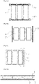
- a rigid envelope (2) consisting of four vertical walls is used.
- the rigid envelope has no lower and upper horizontal walls. Only the two perpendicular walls oriented perpendicular to the plane of the figure are represented on the figure 2b .
- the height of the vertical walls is greater than that of the elements.
- the plurality of elements (7) are placed in the rigid envelope (2). The placement or centering of the elements can be facilitated using a template.
- the silicone gel (4) is poured into the inter-element spaces and into the spaces between the elements and the vertical walls of the rigid envelope.
- This variant allows good wedging of the elements in a plane perpendicular to the longitudinal axis of the elements because the silicone gel absorbs the movements of the elements in this plane.
- the height over which the silicone gel extends can be adjusted to cover almost the entire height of the element container.
- the silicone gel can extend over a height representing at least 25% or at least 50% or at least 75% or at least 90% of the height of the containers.
- This embodiment also has the advantage of allowing access to the lid and to the bottom of the element container. Access to the cover allows power connections to be made using heavy section metal strips.
- a rigid casing consisting of four vertical walls, a lower horizontal wall (8) and a removable cover (9) is used.
- a layer of silicone is deposited on the internal face of the lower horizontal wall.
- the plurality of elements are placed on the silicone layer. The placement or centering of the elements can be facilitated using a template.
- the silicone gel is poured into the inter-element spaces and into the spaces between the elements and the vertical walls of the rigid envelope.
- the upper part is covered with silicone gel leaving free access to the current output terminals of the elements.
- the envelope is closed by the lid.
- This variant allows both a good wedging of the elements in a plane perpendicular to the longitudinal axis of the elements and in a direction along the longitudinal axis of the elements.
- the lower horizontal wall and/or the removable cover can be removed.
- the battery then is a block of silicone gel in which the elements are embedded.
- the elements (7) are aligned in a direction along their longitudinal axis.
- the holding structure (2) has the shape of a tube of circular, rectangular or square section.
- the silicone gel (4) is placed in the inter-element space and in the space between the elements and the inner wall of the tube.
- the cushioning material can be used to cushion the elements of a battery intended to be used in a means of land transport, a means of road transport, a means of rail transport, a means of maritime or river transport, an aircraft, a truck.
- LEO low earth orbit
- GEO geostationary
- a cylindrical-shaped lithium-ion cell was wedged in silicone gel in a holding structure according to the first embodiment illustrated in figures 1a and 1b .
- the element was oriented either upside down, i.e. with the current output terminals facing down ( Picture 1a ), or head up, i.e. with the current output terminals oriented upwards ( Figure 1b ).
- Two silicone gels Gel 1 and Gel 2 were tested.
- Gel 1 has a penetrability of 260 units.
- Gel 2 has a penetrability of less than 200 units.
- a polyurethane resin is the reference wedging material.
- the element wedged by the holding structure is placed on a vibration pot.
- the pot can generate vibrations in a direction perpendicular to the longitudinal axis of the element or in the direction of the longitudinal axis of the element.
- An accelerometer is always placed at the top of the element, on its circumference, the most restrictive location since the element is held only by the base on the opposite side.
- the vibration levels expressed in g 2 /Hz, describe the energy injected by the vibrations at a given frequency.
- the level of vibration measured on the element also called rejected DSP, is compared to the level of vibration applied to the element by the vibration pot, also called injected DSP.
- the objective was to determine with a sine sweep, the frequencies at which an increase in the rejected signal is detected compared to the injected signal. This increase corresponds to an amplification of the signal.
- the frequencies, at which an amplification of the signal appears, are called resonance frequencies F.
- the amplification Q is defined as the square root of the ratio between the spectral density of rejected power and the spectral density of injected power at the resonant frequency.
- Table 2 Upside down element Upside-down element Criterion on frequency >140 Hz Polyurethane resin Silicone gel 1 Polyurethane resin Silicon gel 2 1st resonance frequency detected (Hz) for a vibration perpendicular to the longitudinal axis of the element 275 181 369 232 yes 1st resonance frequency detected (Hz) for a vibration along the longitudinal axis of the element 1841 713 369 1041 yes
- gel 1 and gel 2 satisfy the criterion of a resonance frequency greater than 140 Hz.
- the vibration levels applied to the element are given in Table 3.
- Table 3 Frequency (Hz) DSP level Vibration in a direction perpendicular to the longitudinal axis of the element. 20-80 +3 db/octave 80-100 0.093 g 2 /Hz 100-1000 0.1 g 2 /Hz Vibration in one direction along the longitudinal axis of the element. 1000-2000 -3dB/octave 20-100 +3dB/octave 100-400 0.3 g 2 /Hz 400-2000 -3dB/octave
- the vibration levels applied are represented on a DSP curve as a function of the vibration frequency (Hz).
- the DSP curves were plotted for an element oriented upside down, for a wedging material consisting either of polyurethane resin or of silicone gel 1.
- a wedging material consisting either of polyurethane resin or of silicone gel 1.
- polyurethane resin an amplification of the DSP over almost the entire frequency range swept, whether in the direction of the longitudinal axis or in a direction perpendicular to the longitudinal axis of the element.
- the rejected DSP (B) is above the DSP (A) over almost the entire range of swept frequencies ( Figures 3a and 3b ).
- silicone gel 1 there is a reduction in the rejected DSP, for frequencies ranging from 200 to 800 Hz or greater than 1050 Hz, for a vibration applied in the direction perpendicular to the longitudinal axis of the element. ( Figure 3c ). There is also a reduction in the rejected DSP for a frequency greater than 150 Hz, for a vibration applied in the direction of the longitudinal axis of the element ( 3d figure ).
- the DSP curves were plotted for an element oriented head up, for a wedging material consisting of either polyurethane resin or silicone gel 2.
- a wedging material consisting of either polyurethane resin or silicone gel 2.
- silicone gel 2 there is a reduction in PSD, for frequencies ranging from 350 to 1050 Hz, in the direction perpendicular to the longitudinal axis of the element ( Figure 4c ).
- PSD for a frequency above 350 Hz, in the direction of the longitudinal axis of the element ( Figure 4d ).
- silicone gel therefore allows a reduction of the DSP for certain frequency ranges when the vibrations are applied in the longitudinal axis of the element.
- This property of damping the vibration in the longitudinal axis of the element is remarkable because in the experimental setup of the figures 1a and 1b used for these tests, it is noted that the silicone gel is positioned only around the side wall of the elements and not on the cover or the bottom of the element. Reduction of PSD would therefore be expected to a greater extent for vibrations applied perpendicular to the longitudinal axis of the element than in the direction of the longitudinal axis of the element.
- gel 2 which has a penetrability of less than 200 units, reduces the DSP in the longitudinal direction of the element in a linear manner from 350 Hz.
- Gel 1 which has a penetrability of 260 units, certainly reduces the DSP in the longitudinal direction of the element from 350 Hz, but more randomly, as shown in the 3d figure .
- the G RMS parameter corresponds to the averaged global acceleration (root of the DSP integral by the frequency which is the area under the DSP curve) over the complete range of swept frequencies, i.e. from 20 to 2000 Hz.
- the exploitation of the DSP curves of the figures 3a to 3d and 4a to 4d makes it possible to calculate the value of the parameter G RMS .
- a comparison can be made between the value of the G RMS parameter obtained with silicone gels and that obtained with polyurethane resin.
- the value of G RMS is 30% lower than that of polyurethane resin in the direction perpendicular to the longitudinal axis of the element (20.6 vs. 29 ,5).
- the value of G RMS is 82% lower than that of polyurethane resin in the direction of the longitudinal axis of the element (8.5 vs. 46.9).
- the value of G RMS rejected is even lower than that of G RMS injected (8.5 vs. 17.3).
- G RMS is equivalent to that of polyurethane resin in the direction perpendicular to the longitudinal axis of the element.
- the G RMS value is 36% lower than that of polyurethane resin in the direction of the longitudinal axis of the element (15.6 vs. 24.2).
- the value of G RMS rejected is even lower than that of G RMS injected (15.5 vs. 17.3).
- Gels 1 and 2 therefore reduce the DSP in the direction of the longitudinal axis of the element.
- Tables 5 and 6 show the values of the parameter ⁇ of Miles' formula for the head-up and head-down orientations of the element.
- Table 5 Direction perpendicular to the longitudinal axis of the element Upside down head up Polyurethane resin Silicone gel 1 Polyurethane resin Silicon gel 2 injected Rejected injected Rejected injected Rejected F(Hz) 272 272 112 112 270 270 180 180 P ( g2 /Hz) 0.11 7.01 0.081 3,671 0.1 6.5 0.1 12 ⁇ (g) 19.4 9.8 18.5 17.6 Q 8.0 6.7 8.1 11.0 Direction along the longitudinal axis of the element Upside down head up Polyurethane resin Silicone gel 1 Polyurethane resin Silicon gel 2 injected Rejected injected Rejected injected Rejected F(Hz) 1780 1780 100 100 1790 1790 150 150 P ( g2 /Hz) 0.08 6.75 0.359 0.715 0.65 1.7 0.3 1 ⁇ (g
- Tables 5 and 6 show that the ⁇ accelerations at the resonant frequency for gels 1 and 2 are lower than those of the polyurethane resin.
Landscapes
- Chemical & Material Sciences (AREA)
- Chemical Kinetics & Catalysis (AREA)
- Electrochemistry (AREA)
- General Chemical & Material Sciences (AREA)
- Sealing Battery Cases Or Jackets (AREA)
Applications Claiming Priority (1)
| Application Number | Priority Date | Filing Date | Title |
|---|---|---|---|
| FR2103072A FR3121285B1 (fr) | 2021-03-26 | 2021-03-26 | Matériau de calage d’éléments électrochimiques dans une batterie |
Publications (1)
| Publication Number | Publication Date |
|---|---|
| EP4071908A1 true EP4071908A1 (de) | 2022-10-12 |
Family
ID=76730671
Family Applications (1)
| Application Number | Title | Priority Date | Filing Date |
|---|---|---|---|
| EP22163573.3A Pending EP4071908A1 (de) | 2021-03-26 | 2022-03-22 | Material zum fixieren von elektrochemischen elementen in einer batterie |
Country Status (2)
| Country | Link |
|---|---|
| EP (1) | EP4071908A1 (de) |
| FR (1) | FR3121285B1 (de) |
Citations (7)
| Publication number | Priority date | Publication date | Assignee | Title |
|---|---|---|---|---|
| JPH08106886A (ja) * | 1994-10-03 | 1996-04-23 | Asahi Chem Ind Co Ltd | 電 池 |
| US20050095499A1 (en) * | 2001-12-28 | 2005-05-05 | Hideyuki Kanai | Battery pack and rechargeable vacuum cleaner |
| EP2403050A1 (de) | 2010-07-02 | 2012-01-04 | Saft | Batterie von elektrochemischen Generatoren, die einen Schaumstoff als Füllmaterial zwischen Generatoren umfasst |
| CN108023039A (zh) * | 2017-10-19 | 2018-05-11 | 惠州时代电池有限公司 | 电池组合件 |
| KR20190091631A (ko) * | 2018-01-29 | 2019-08-07 | 주식회사티움리서치 | 진동흡수형 전지 셀 고정 홀더 및 이를 구비한 전지 팩 |
| WO2020094365A1 (en) | 2018-11-05 | 2020-05-14 | Xerotech Limited | A battery pack and a method of manufacturing a battery pack |
| US20200203679A1 (en) * | 2018-12-25 | 2020-06-25 | Honda Motor Co.,Ltd. | Cell structure of solid state battery and manufacturing method of solid state battery |
-
2021
- 2021-03-26 FR FR2103072A patent/FR3121285B1/fr active Active
-
2022
- 2022-03-22 EP EP22163573.3A patent/EP4071908A1/de active Pending
Patent Citations (8)
| Publication number | Priority date | Publication date | Assignee | Title |
|---|---|---|---|---|
| JPH08106886A (ja) * | 1994-10-03 | 1996-04-23 | Asahi Chem Ind Co Ltd | 電 池 |
| US20050095499A1 (en) * | 2001-12-28 | 2005-05-05 | Hideyuki Kanai | Battery pack and rechargeable vacuum cleaner |
| EP2403050A1 (de) | 2010-07-02 | 2012-01-04 | Saft | Batterie von elektrochemischen Generatoren, die einen Schaumstoff als Füllmaterial zwischen Generatoren umfasst |
| CN108023039A (zh) * | 2017-10-19 | 2018-05-11 | 惠州时代电池有限公司 | 电池组合件 |
| KR20190091631A (ko) * | 2018-01-29 | 2019-08-07 | 주식회사티움리서치 | 진동흡수형 전지 셀 고정 홀더 및 이를 구비한 전지 팩 |
| WO2020094365A1 (en) | 2018-11-05 | 2020-05-14 | Xerotech Limited | A battery pack and a method of manufacturing a battery pack |
| WO2020094364A1 (en) * | 2018-11-05 | 2020-05-14 | Xerotech Limited | A duct and a method of manufacturing a duct |
| US20200203679A1 (en) * | 2018-12-25 | 2020-06-25 | Honda Motor Co.,Ltd. | Cell structure of solid state battery and manufacturing method of solid state battery |
Non-Patent Citations (2)
| Title |
|---|
| ANONYMOUS: "Accelerate your transportation revolution with Electronic Silicone Solutions", ELKEM, 1 January 2018 (2018-01-01), pages 1 - 24, XP093074644, Retrieved from the Internet <URL:https://www.hisco.com/userfiles/images/landingpages/elkem/elkememobility/ev_2020_brochure_electronic_vehicles.pdf> [retrieved on 20230817] |
| ANONYMOUS: "SILICONE GEL SOLUTIONS", WACKER CHEMIE AG, 1 September 2016 (2016-09-01), pages 1 - 16, XP093074649, Retrieved from the Internet <URL:https://www.wacker.com/h/medias/6982-EN.pdf> [retrieved on 20230817] |
Also Published As
| Publication number | Publication date |
|---|---|
| FR3121285A1 (fr) | 2022-09-30 |
| FR3121285B1 (fr) | 2023-03-03 |
Similar Documents
| Publication | Publication Date | Title |
|---|---|---|
| EP3208866B1 (de) | Kompensationssystem der quellung von elektrochemischen elementen | |
| EP2403050B1 (de) | Batterie von elektrochemischen Generatoren, die einen Schaumstoff als Füllmaterial zwischen Generatoren umfasst | |
| FR3116657A1 (fr) | Accumulateur métal-ion muni d’un conduit de dégazage, Module de batterie ou Pack-batterie associé à refroidissement liquide. | |
| CA3000587A1 (fr) | Module de stockage d'energie electrique et son procede de fabrication | |
| WO2015097281A1 (fr) | Batterie electrochimique a securite de fonctionnement amelioree en environnement humide | |
| EP4071908A1 (de) | Material zum fixieren von elektrochemischen elementen in einer batterie | |
| FR3119939A1 (fr) | Module de batterie | |
| WO2014131875A1 (fr) | Dispositif de securite pour une batterie de generateurs electrochimiques au lithium | |
| EP3087624A1 (de) | Elektrochemisches batteriemodul mit erhöhter resistenz in feuchten umgebungen und verfahren zur herstellung von mindestens einem derartigen modul | |
| EP3155270B1 (de) | Mittel zum verkeilen eines elektrochemischen generators in einer position in einer batterie | |
| EP3662972B1 (de) | Implantierbares medizinisches gerät mit verbesserter architektur | |
| FR2601819A1 (fr) | Pile electrochimique et son procede de fabrication | |
| EP3948905A1 (de) | Kapazitiver block mit einem abstandshalter | |
| EP4564538B1 (de) | Batteriemodul mit mindestens einem speicher mit einem phasenveränderlichen metallpulver zur begrenzung der ausbreitung von thermischem durchgehen und der druckerhöhung dafür | |
| FR3121265A1 (fr) | Ensemble pour le transport d’hexafluorure d’uranium | |
| EP4468438A1 (de) | Verfahren zur herstellung einer lithium-metall- oder natrium-metall-festkörperbatterie aus einem elektrochemischen flüssigelektrolyt-akkumulator zur thermischen unschädlichmachung | |
| FR3150046A1 (fr) | Pack-batterie comportant un fluide caloporteur apte à contenir l’emballement thermique des accumulateurs électrochimiques du pack-batterie | |
| WO2024033575A1 (fr) | Emballage, conditionnement avec un tel emballage, utilisation d'un tel emballage, équipement de malaxage et procédé de chargement et/ou déchargement | |
| EP4092796A1 (de) | Batteriemodul | |
| WO2026008946A1 (fr) | Dispositif de gestion thermique pour une batterie électrique | |
| FR3136116A1 (fr) | Pack batterie avec dispositif de retardement de propagation d’incendie | |
| FR3001338A1 (fr) | Module de batterie et procede de fabrication | |
| CN121983728A (en) | Battery compartment structure of node instrument and pouring sealant method thereof | |
| FR3121264A1 (fr) | Ensemble pour le transport d’hexafluorure d’uranium, comprenant des capots amortisseurs de choc | |
| WO2022106426A1 (fr) | Cellule électrochimique de type pouch pour un dispositif de stockage d'énergie |
Legal Events
| Date | Code | Title | Description |
|---|---|---|---|
| PUAI | Public reference made under article 153(3) epc to a published international application that has entered the european phase |
Free format text: ORIGINAL CODE: 0009012 |
|
| STAA | Information on the status of an ep patent application or granted ep patent |
Free format text: STATUS: THE APPLICATION HAS BEEN PUBLISHED |
|
| AK | Designated contracting states |
Kind code of ref document: A1 Designated state(s): AL AT BE BG CH CY CZ DE DK EE ES FI FR GB GR HR HU IE IS IT LI LT LU LV MC MK MT NL NO PL PT RO RS SE SI SK SM TR |
|
| STAA | Information on the status of an ep patent application or granted ep patent |
Free format text: STATUS: REQUEST FOR EXAMINATION WAS MADE |
|
| 17P | Request for examination filed |
Effective date: 20230412 |
|
| RBV | Designated contracting states (corrected) |
Designated state(s): AL AT BE BG CH CY CZ DE DK EE ES FI FR GB GR HR HU IE IS IT LI LT LU LV MC MK MT NL NO PL PT RO RS SE SI SK SM TR |
|
| P01 | Opt-out of the competence of the unified patent court (upc) registered |
Effective date: 20230514 |
|
| TPAC | Observations filed by third parties |
Free format text: ORIGINAL CODE: EPIDOSNTIPA |
|
| STAA | Information on the status of an ep patent application or granted ep patent |
Free format text: STATUS: EXAMINATION IS IN PROGRESS |
|
| 17Q | First examination report despatched |
Effective date: 20241004 |