EP3662972B1 - Implantierbares medizinisches gerät mit verbesserter architektur - Google Patents
Implantierbares medizinisches gerät mit verbesserter architektur Download PDFInfo
- Publication number
- EP3662972B1 EP3662972B1 EP19212796.7A EP19212796A EP3662972B1 EP 3662972 B1 EP3662972 B1 EP 3662972B1 EP 19212796 A EP19212796 A EP 19212796A EP 3662972 B1 EP3662972 B1 EP 3662972B1
- Authority
- EP
- European Patent Office
- Prior art keywords
- layer
- housing
- deposited
- thermal paste
- internal space
- Prior art date
- Legal status (The legal status is an assumption and is not a legal conclusion. Google has not performed a legal analysis and makes no representation as to the accuracy of the status listed.)
- Active
Links
Images


Classifications
-
- H—ELECTRICITY
- H05—ELECTRIC TECHNIQUES NOT OTHERWISE PROVIDED FOR
- H05K—PRINTED CIRCUITS; CASINGS OR CONSTRUCTIONAL DETAILS OF ELECTRIC APPARATUS; MANUFACTURE OF ASSEMBLAGES OF ELECTRICAL COMPONENTS
- H05K5/00—Casings, cabinets or drawers for electric apparatus
- H05K5/06—Hermetically-sealed casings
- H05K5/069—Other details of the casing, e.g. wall structure, passage for a connector, a cable, a shaft
-
- A—HUMAN NECESSITIES
- A61—MEDICAL OR VETERINARY SCIENCE; HYGIENE
- A61N—ELECTROTHERAPY; MAGNETOTHERAPY; RADIATION THERAPY; ULTRASOUND THERAPY
- A61N1/00—Electrotherapy; Circuits therefor
- A61N1/18—Applying electric currents by contact electrodes
- A61N1/32—Applying electric currents by contact electrodes alternating or intermittent currents
- A61N1/36—Applying electric currents by contact electrodes alternating or intermittent currents for stimulation
- A61N1/372—Arrangements in connection with the implantation of stimulators
- A61N1/375—Constructional arrangements, e.g. casings
- A61N1/3758—Packaging of the components within the casing
-
- H—ELECTRICITY
- H05—ELECTRIC TECHNIQUES NOT OTHERWISE PROVIDED FOR
- H05K—PRINTED CIRCUITS; CASINGS OR CONSTRUCTIONAL DETAILS OF ELECTRIC APPARATUS; MANUFACTURE OF ASSEMBLAGES OF ELECTRICAL COMPONENTS
- H05K7/00—Constructional details common to different types of electric apparatus
- H05K7/14—Mounting supporting structure in casing or on frame or rack
- H05K7/1422—Printed circuit boards receptacles, e.g. stacked structures, electronic circuit modules or box like frames
- H05K7/1427—Housings
-
- H—ELECTRICITY
- H05—ELECTRIC TECHNIQUES NOT OTHERWISE PROVIDED FOR
- H05K—PRINTED CIRCUITS; CASINGS OR CONSTRUCTIONAL DETAILS OF ELECTRIC APPARATUS; MANUFACTURE OF ASSEMBLAGES OF ELECTRICAL COMPONENTS
- H05K7/00—Constructional details common to different types of electric apparatus
- H05K7/20—Modifications to facilitate cooling, ventilating, or heating
- H05K7/2039—Modifications to facilitate cooling, ventilating, or heating characterised by the heat transfer by conduction from the heat generating element to a dissipating body
-
- H—ELECTRICITY
- H05—ELECTRIC TECHNIQUES NOT OTHERWISE PROVIDED FOR
- H05K—PRINTED CIRCUITS; CASINGS OR CONSTRUCTIONAL DETAILS OF ELECTRIC APPARATUS; MANUFACTURE OF ASSEMBLAGES OF ELECTRICAL COMPONENTS
- H05K7/00—Constructional details common to different types of electric apparatus
- H05K7/20—Modifications to facilitate cooling, ventilating, or heating
- H05K7/2039—Modifications to facilitate cooling, ventilating, or heating characterised by the heat transfer by conduction from the heat generating element to a dissipating body
- H05K7/20436—Inner thermal coupling elements in heat dissipating housings, e.g. protrusions or depressions integrally formed in the housing
- H05K7/20445—Inner thermal coupling elements in heat dissipating housings, e.g. protrusions or depressions integrally formed in the housing the coupling element being an additional piece, e.g. thermal standoff
- H05K7/20454—Inner thermal coupling elements in heat dissipating housings, e.g. protrusions or depressions integrally formed in the housing the coupling element being an additional piece, e.g. thermal standoff with a conformable or flexible structure compensating for irregularities, e.g. cushion bags, thermal paste
-
- A—HUMAN NECESSITIES
- A61—MEDICAL OR VETERINARY SCIENCE; HYGIENE
- A61N—ELECTROTHERAPY; MAGNETOTHERAPY; RADIATION THERAPY; ULTRASOUND THERAPY
- A61N1/00—Electrotherapy; Circuits therefor
- A61N1/18—Applying electric currents by contact electrodes
- A61N1/32—Applying electric currents by contact electrodes alternating or intermittent currents
- A61N1/36—Applying electric currents by contact electrodes alternating or intermittent currents for stimulation
- A61N1/36036—Applying electric currents by contact electrodes alternating or intermittent currents for stimulation of the outer, middle or inner ear
- A61N1/36038—Cochlear stimulation
-
- A—HUMAN NECESSITIES
- A61—MEDICAL OR VETERINARY SCIENCE; HYGIENE
- A61N—ELECTROTHERAPY; MAGNETOTHERAPY; RADIATION THERAPY; ULTRASOUND THERAPY
- A61N1/00—Electrotherapy; Circuits therefor
- A61N1/18—Applying electric currents by contact electrodes
- A61N1/32—Applying electric currents by contact electrodes alternating or intermittent currents
- A61N1/36—Applying electric currents by contact electrodes alternating or intermittent currents for stimulation
- A61N1/3605—Implantable neurostimulators for stimulating central or peripheral nerve system
-
- A—HUMAN NECESSITIES
- A61—MEDICAL OR VETERINARY SCIENCE; HYGIENE
- A61N—ELECTROTHERAPY; MAGNETOTHERAPY; RADIATION THERAPY; ULTRASOUND THERAPY
- A61N1/00—Electrotherapy; Circuits therefor
- A61N1/18—Applying electric currents by contact electrodes
- A61N1/32—Applying electric currents by contact electrodes alternating or intermittent currents
- A61N1/36—Applying electric currents by contact electrodes alternating or intermittent currents for stimulation
- A61N1/372—Arrangements in connection with the implantation of stimulators
- A61N1/375—Constructional arrangements, e.g. casings
- A61N1/37512—Pacemakers
-
- A—HUMAN NECESSITIES
- A61—MEDICAL OR VETERINARY SCIENCE; HYGIENE
- A61N—ELECTROTHERAPY; MAGNETOTHERAPY; RADIATION THERAPY; ULTRASOUND THERAPY
- A61N1/00—Electrotherapy; Circuits therefor
- A61N1/18—Applying electric currents by contact electrodes
- A61N1/32—Applying electric currents by contact electrodes alternating or intermittent currents
- A61N1/36—Applying electric currents by contact electrodes alternating or intermittent currents for stimulation
- A61N1/372—Arrangements in connection with the implantation of stimulators
- A61N1/375—Constructional arrangements, e.g. casings
- A61N1/37514—Brain implants
Definitions
- the present invention relates to an implantable medical device.
- the implantable medical device of the invention has the particularity of being very resistant to impact.
- Patent application no. WO2006 / 081361A2 relates to cochlear implants. It describes a device which comprises a hermetic container in which the electronics of the device are placed and a cover which is affixed to the hermetic container and defining a non-hermetic internal space with said container.
- the patent application specifies that a material including silicone can be injected into this internal space, in particular with a view to reinforcing the impact resistance of the device.
- the architecture proposed in this document is not satisfactory because it does not make it possible to meet all the constraints mentioned above. Indeed, it does not allow good heat dissipation since the electronics are isolated in the hermetic container, no solution being provided to dissipate the heat generated in operation. In addition, it does not make it possible to respond to the various types of shocks that may occur, these being able to cause elastic deformations or plastic deformations of the device.
- the aim of the invention is therefore to provide an implantable medical device which overcomes the drawbacks of the state of the art and which can meet the various operating constraints listed above.
- the structure of the third layer is produced in the form of several concentric cavities.
- the structure of the third layer comprises several parallel rectilinear cavities forming trenches and a comb structure having several teeth of determined height and width.
- the structure of the third layer comprises a spiral.
- each cavity of the structure is through.
- the second layer is formed from a metal of high thermal conductivity such as copper, gold or aluminum.
- the thermal paste of the first layer and of the third layer has a thermal conductivity of between 1 and 12 W / m / K.
- the first layer and the third layer comprises filled silicone.
- the heat dissipation and shock absorption module comprises one or more additional layers made of pyrolytic graphite, deposited under the second layer and between the third layer and the internal wall of the case.
- the invention also relates to a method of manufacturing an implantable medical device as defined above, the structure of the third layer being produced by applying cookie cutters to a layer of thermal paste deposited on a substrate, by molding by compression or injection molding in a chemically soluble or thermally liquefiable mold.
- the solution of the invention applies mainly to active implantable medical devices (AIMD), in particular those whose energy consumption is high.
- Implantable pacemaker type stimulators have been the subject of numerous optimizations and consume very little electrical energy (a few ⁇ W) and therefore dissipate very little heat.
- recording systems of the BCI ("Brain Computer Interface") type can consume up to 350mW (see referenced publication " Mestais, CS, Charvet, G., Sauter-Starace, F., Foerster, M., Ratel, D., & Benabid, AL (2015).
- WIMAGINE wireless 64-channel ECoG recording implant for long term clinical applications. IEEE transactions on neural systems and rehabilitation engineering, 23 (1), 10-21 "). For these devices, the issue of effective and consistent energy extraction becomes critical.
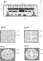
- an implantable medical device comprises a housing 1 which can be produced in two parts assembled one on the other, a first part, called lower, forming a container, and a second part, called upper, forming a cover positioned on the container.
- the housing 1 is hermetically closed and defines an internal space isolated from the outside.
- the hermeticity between the two parts can be achieved by any known means.
- the device comprises an electronic card 2.
- the electronic card 2 has two faces, each of its faces being able to support one or more electronic components 20.
- the device may include a frame 3 housed in the bottom of one of the two parts of the housing 1, on which the electronic card 2 is fixed. figure 1 , the frame 3 is positioned in the bottom of the container.
- the card 2 is mounted by its underside on the frame and can be fixed on the frame 3 by any suitable means.
- the frame 3 can be an independent part fixed in the bottom of the housing container, for example by screws, or directly molded with the housing container so as to present support members for the electronic card 2.
- the implantable medical device also comprises a module 4 for heat dissipation and shock absorption.
- This module 4 comprises a set of several superimposed layers 40, 41, 42.
- the set of superimposed layers comprises a lower face deposited on the upper face of the electronic card 2, opposite its lower face for fixing to the frame 3 and an upper face against which the internal wall 10 of the upper part of the housing 1 comes to rest, making it possible to wedge the heat dissipation and shock absorption device in the housing and to serve as a shock absorber when the housing receives shocks on its upper face.
- the first layer 40 and the third layer 42 can be made from the same thermal paste.
- this material is chosen to ensure excellent thermal conductivity and to have a sufficiently deformable composition to absorb shocks.
- the material chosen to make the thermal paste can be filled silicone. It can thus contain zinc oxide, in addition to the silicone which is used as a binding agent allowing the thermal conductivity to go from 0.2W / m / K to values between 3 and 5W / m / K. If the electrical insulation of the components is ensured by an acrylic-type varnish or an epoxy layer, other thermal pastes can also be cited with thermal conductivities of up to 12W / m / K.
- the material called "Prolimatech PK1" (registered trademark) is composed of 60 to 85% aluminum, 15-25% zinc oxide, 12-20% silicone oil and finally an antioxidant.
- thermal conductive pastes such as the one called “Arctic Silver 5" (registered trademark) additionally contain silver particles.
- Others make use of graphite, such as the paste referenced “WLPG 10" (registered trademark) from Fischer Elektronik, which does not use silicone and has excellent thermal conductivity (10.5 W / m ⁇ K).
- WLPG 10 registered trademark
- the thermal paste used has a thermal conductivity of between 1 and 12 W / m / K.
- the second layer 41 used is advantageously a metal layer in order to integrate a material with high thermal conductivity in the heat dissipation and shock absorption module 4. It can be a plate of copper, gold or aluminum. The second layer can have a thickness between 0.1 and 0.6mm. As this second layer turns out to be relatively rigid, the third layer made of a more flexible and deformable material is necessary to ensure a shock absorption function and to provide an implantable device which has a higher level of deformability than a device which would only include a single metal layer placed between the card and the cover.
- the heat dissipation and shock absorption module 4 may include one or more additional layers made of pyrolytic graphite, deposited under the copper layer and possibly between the third layer 42 and the wall. internal 10 of the housing cover.
- the third layer 42 made of thermal paste, is said to be structured.
- structured is understood to mean that it has several cavities in order to improve its deformability and thus better protect the electronic assembly from shocks. The structure is thus produced to alternate solid parts and hollow parts.
- the cavities can be through (that is to say made through the entire thickness of the layer) or not.
- the structure of the third layer 42 may include a mixture of several cavities, some being through and others not.
- the figures 2A to 2D show several examples of possible structures at the level of the third layer.
- the structure is said to be comb. It thus comprises several parallel rectilinear transverse trenches 420, thus forming several parallel sleepers or teeth.
- the structure comprises several through cavities 421 in a rectangle, arranged concentrically. Two cavities following two rectilinear trenches perpendicular to each other can also be added.
- the structure comprises several circular through cavities 422 or elliptical, arranged concentrically.
- the structure comprises several circular through cavities 423, arranged concentrically, two rectilinear and perpendicular trenches between them being added.
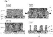
- the figures 3 to 5 show several distinct methods of making a comb structure, such as that of the figure 2A , in a thermal paste.
- the figure 4 shows a second method of producing the structured layer. This solution can be implemented directly on the second layer 41 of the thermal dissipation and shock absorption module 4 or on a separate substrate.
- This negative structure which is chemically soluble or preferably liquefied at temperature is used.
- This negative structure can be a heat-sensitive mold 60 made of wax or paraffin (solid / liquid transition temperature close to 45 ° C.), which comprises a base and structures in relief.
- E30 and E40 The whole is heated until partial and then complete dissolution of the mold 60 used. There then remains only the desired structured layer 42, following the disappearance of the mold.
- the figure 5 shows a final method of generating the structure in the third layer of the module.
- E100 A layer 70 of thermal paste is deposited directly, with a homogeneous thickness, on the second layer 41 of module 4.
- a mold 70 is applied by compression against the layer 70 until it passes through it.
- the mold 70 is of a shape adapted to the structure to be obtained.
- E400 The mold 70 is removed in order to obtain the third layer 42 with the chosen structure.
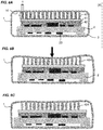
- the figures 6A to 6C represent the device according to the invention subjected to a deformation going beyond its elastic limit and makes it possible to visualize the principle of mechanical absorption allowed by the device.
- the structure has a shape conforming to that of the figure 2A , in a comb with several cross members in parallel.
- the housing 1 When the housing 1 is subjected to a mechanical stress, it deforms first in the elastic domain (reversible deformation) then in the plastic domain (irreversible deformation).
- the challenge of the invention is thus to absorb part of the deformation energy to avoid damaging the electronics in the case and compromising the hermeticity of the device.
- the mechanical shock generates a deformation of the housing 1 and therefore a compression of the cross members 424 of the structure of the third layer 42.
- the housing 1 After the mechanical shock, the housing 1 returns to its initial shape if there has been no plastic deformation.
- the heat dissipation and shock absorption module 4, in particular its third structured layer 42, will have made it possible to absorb part of the energy and limit the deformation of the housing and prevent it from damaging the housing. electronic part of the device.
- the deformation of the tooth In a stationary regime, the deformation of the tooth is homogeneous and symmetrical with respect to the neutral fiber. If the elongation (h / e) is very high (> 10), buckling may occur in the tooth, which then deforms mainly on one side.
- h / e is very high (> 10)
- buckling may occur in the tooth, which then deforms mainly on one side.
- a large amount of energy is dissipated by plastic deformation.
- This force is greater by a factor of n, where n is the number of teeth which is also dependent on the resolution of the embodiment.
- a first type of simulation has been established to compare the behavior of unstructured thermal paste with that of structured thermal paste.
- the unstructured thermal paste was considered as a hexahedron of dimensions: Depth 10 x width 4.8 x height 3 mm 3 .
- This comb consists of 8 identical teeth.
Landscapes
- Engineering & Computer Science (AREA)
- Microelectronics & Electronic Packaging (AREA)
- Health & Medical Sciences (AREA)
- Physics & Mathematics (AREA)
- Thermal Sciences (AREA)
- Nuclear Medicine, Radiotherapy & Molecular Imaging (AREA)
- Biomedical Technology (AREA)
- Radiology & Medical Imaging (AREA)
- Life Sciences & Earth Sciences (AREA)
- Animal Behavior & Ethology (AREA)
- General Health & Medical Sciences (AREA)
- Public Health (AREA)
- Veterinary Medicine (AREA)
- Cooling Or The Like Of Electrical Apparatus (AREA)
- Electrotherapy Devices (AREA)
Claims (10)
- Implantierbares medizinisches Gerät, umfassend:- ein hermetisch dichtes Gehäuse (1), das einen Innenraum definiert,- mindestens eine Leiterplatte (2), die in dem Innenraum des Gehäuses aufgenommen ist, wobei die Leiterplatte elektronische Bauelemente trägt,- ein Wärmeableitungs- und Stoßabsorptionsmodul (4), das in dem Innenraum des Gehäuses aufgenommen ist und zwischen der Leiterplatte (2) und einer Innenwand (10) des Gehäuses angeordnet ist, dadurch gekennzeichnet, dass das Wärmeableitungs- und Stoßabsorptionsmodul beinhaltet:- eine erste Schicht (40) aus Wärmeleitpaste, die in dem Innenraum des Gehäuses platziert ist und auf die Leiterplatte (2) aufgebracht ist,- eine zweite Metallschicht (41) mit hoher Wärmeleitfähigkeit, die auf die erste Schicht (40) aufgebracht ist,- eine dritte Schicht (42) aus Wärmeleitpaste, die auf die zweite Schicht (41) aufgebracht ist und so angeordnet ist, dass sie an der Innenwand (10) des Gehäuses anliegt, wobei die dritte Schicht (42) eine Struktur beinhaltet, die mehrere Kavitäten aufweist, die über den gesamten Kontaktbereich der dritten Schicht mit der Innenwand des Gehäuses verteilt sind.
- Gerät nach Anspruch 1, dadurch gekennzeichnet, dass die Struktur der dritten Schicht (42) in Form mehrerer konzentrischer Kavitäten (422) ausgeführt ist.
- Gerät nach Anspruch 1, dadurch gekennzeichnet, dass die Struktur der dritten Schicht (42) mehrere parallele geradlinige Kavitäten (420) beinhaltet, die Gräben bilden, und eine Kammstruktur, die mehrere Zinken mit bestimmter Höhe und Breite aufweist.
- Gerät nach Anspruch 1, dadurch gekennzeichnet, dass die Struktur der dritten Schicht (42) eine Spirale beinhaltet.
- Gerät nach einem der Ansprüche 1 bis 4, dadurch gekennzeichnet, dass jede Kavität der Struktur durchgehend ist.
- Gerät nach einem der Ansprüche 1 bis 5, dadurch gekennzeichnet, dass die zweite Schicht (41) aus einem Metall mit starker Wärmeleitfähigkeit wie Kupfer, Gold oder Aluminium gebildet ist.
- Gerät nach einem der Ansprüche 1 bis 6, dadurch gekennzeichnet, dass die Wärmeleitpaste der ersten Schicht (40) und der dritten Schicht (42) eine Wärmeleitfähigkeit zwischen 1 und 12 W/m/K aufweist.
- Gerät nach einem der Ansprüche 1 bis 7, dadurch gekennzeichnet, dass die erste Schicht (40) und die dritte Schicht (42) gefülltes Silikon beinhalten.
- Gerät nach einem der Ansprüche 1 bis 8, dadurch gekennzeichnet, dass das Wärmeableitungs- und Stoßabsorptionsmodul (4) eine oder mehrere zusätzliche Schichten aus pyrolytischem Graphit beinhaltet, die unter der zweiten Schicht (41) und zwischen der dritten Schicht (42) und der Innenwand (10) des Gehäuses aufgebracht sind.
- Verfahren zur Herstellung eines implantierbaren medizinischen Geräts wie in einem der Ansprüche 1 bis 9 definiert, dadurch gekennzeichnet, dass die Struktur der dritten Schicht (42) ausgeführt wird, indem Stanzelemente auf eine Schicht (50) aus Wärmeleitpaste gesetzt werden, die auf ein Substrat (51) aufgebracht ist, durch Formpressen oder Spritzgießen in einem chemisch löslichen oder thermisch verflüssigbaren Formwerkzeug (60).
Applications Claiming Priority (1)
| Application Number | Priority Date | Filing Date | Title |
|---|---|---|---|
| FR1872524A FR3089423B1 (fr) | 2018-12-07 | 2018-12-07 | Dispositif médical implantable à architecture améliorée |
Publications (2)
| Publication Number | Publication Date |
|---|---|
| EP3662972A1 EP3662972A1 (de) | 2020-06-10 |
| EP3662972B1 true EP3662972B1 (de) | 2021-08-25 |
Family
ID=67107512
Family Applications (1)
| Application Number | Title | Priority Date | Filing Date |
|---|---|---|---|
| EP19212796.7A Active EP3662972B1 (de) | 2018-12-07 | 2019-12-02 | Implantierbares medizinisches gerät mit verbesserter architektur |
Country Status (3)
| Country | Link |
|---|---|
| US (1) | US10863643B2 (de) |
| EP (1) | EP3662972B1 (de) |
| FR (1) | FR3089423B1 (de) |
Families Citing this family (1)
| Publication number | Priority date | Publication date | Assignee | Title |
|---|---|---|---|---|
| US11311312B2 (en) * | 2013-03-15 | 2022-04-26 | Medtronic, Inc. | Subcutaneous delivery tool |
Family Cites Families (12)
| Publication number | Priority date | Publication date | Assignee | Title |
|---|---|---|---|---|
| US5768104A (en) * | 1996-02-22 | 1998-06-16 | Cray Research, Inc. | Cooling approach for high power integrated circuits mounted on printed circuit boards |
| US20010033476A1 (en) * | 1999-07-15 | 2001-10-25 | Dibene Joseph T. | Thermal/mechanical springbeam mechanism for heat transfer from heat source to heat dissipating device |
| JP5088788B2 (ja) | 2005-01-27 | 2012-12-05 | コクレア リミテッド | 埋め込み可能医療デバイス |
| FR2898462B1 (fr) * | 2006-03-08 | 2020-02-07 | Thales | Drain thermique pour carte electronique comportant des elements en graphite |
| JP5939102B2 (ja) * | 2012-09-18 | 2016-06-22 | 富士通株式会社 | 電子機器 |
| US9338927B2 (en) * | 2013-05-02 | 2016-05-10 | Western Digital Technologies, Inc. | Thermal interface material pad and method of forming the same |
| US9443789B2 (en) * | 2013-09-11 | 2016-09-13 | Harris Corporation | Embedded electronic packaging and associated methods |
| US10772228B2 (en) * | 2015-11-03 | 2020-09-08 | Medtronic, Inc. | Sealed package including electronic device and power source |
| US20170281936A1 (en) * | 2016-04-01 | 2017-10-05 | Boston Scientific Neuromodulation Corporation | Convertible Implantable Stimulator |
| CN106512213A (zh) * | 2016-12-20 | 2017-03-22 | 北京品驰医疗设备有限公司 | 一种植入式骶神经刺激装置 |
| US10608354B2 (en) * | 2017-03-23 | 2020-03-31 | Verily Life Sciences Llc | Implantable connector with two electrical components |
| US10383253B1 (en) * | 2018-03-27 | 2019-08-13 | Nio Usa, Inc. | Sealable multi-surface electronics thermal conduction package |
-
2018
- 2018-12-07 FR FR1872524A patent/FR3089423B1/fr not_active Expired - Fee Related
-
2019
- 2019-12-02 EP EP19212796.7A patent/EP3662972B1/de active Active
- 2019-12-05 US US16/703,989 patent/US10863643B2/en active Active
Also Published As
| Publication number | Publication date |
|---|---|
| FR3089423A1 (fr) | 2020-06-12 |
| EP3662972A1 (de) | 2020-06-10 |
| FR3089423B1 (fr) | 2020-12-18 |
| US10863643B2 (en) | 2020-12-08 |
| US20200187375A1 (en) | 2020-06-11 |
Similar Documents
| Publication | Publication Date | Title |
|---|---|---|
| EP0197847B1 (de) | Verfahren zur Herstellung von Karten mit elektronischem Speicher und derartig hergestellte Karten | |
| EP2741323B1 (de) | Elektronisches Bauteil und Herstellungsverfahren dieses elektronischen Bauteils | |
| EP3154082B1 (de) | Verbesserte dbc-struktur, die mit einem trägerelement ausgestattet ist, in das ein material mit phasenumwandlung eingebaut ist | |
| EP2803085A1 (de) | Passive wärmeverwaltungsvorrichtung | |
| EP3662972B1 (de) | Implantierbares medizinisches gerät mit verbesserter architektur | |
| FR2910701A1 (fr) | Module de puce et son procede de production | |
| EP2608253A2 (de) | Silizium-Durchkontaktierungspunkt (TSV) einer Struktur zur Freisetzung von Stress, und entsprechendes Herstellungsverfahren | |
| EP3182447B1 (de) | Verbundwerkstoffbauteil zur wärmeabsorption, und herstellungsmethode | |
| FR3073760A1 (fr) | Élément à insérer et son procédé de fabrication | |
| EP3728163B1 (de) | Verbessertes wärmematerial mit hoher kapazität und hoher leitfähigkeit, verfahren zur herstellung davon und komponenten damit | |
| EP1050845B1 (de) | Verfahren zum Einsetzen eines Microchips in eine Kartenausnehmung | |
| EP3115128A1 (de) | Anordnung, die zwei elemente mit unterschiedlichen wärmeausdehnungskoeffizienten und eine sinterdichtung mit heterogener dichte umfasst, und herstellungsverfahren dieser anordnung | |
| EP2791969B1 (de) | Herstellung einer elektrischen durchgangsverbindung | |
| EP0641469B1 (de) | Verfahren zur herstellung einer karte, die mindestens einen elektronischen baustein enthält | |
| FR2867303A1 (fr) | Condensateur en pastille isolee pour montage en surface | |
| FR2971233A1 (fr) | Substrat amortissant pour panneau structurel de satellite | |
| EP2647065B1 (de) | Polymer mit leitenden Zonen an bestimmten Stellen | |
| FR3098646A1 (fr) | Composant electronique resistant a l'humidite et procede de realisation d'un tel composant | |
| FR2597695A1 (fr) | Boitier assurant la stabilisation thermique des equipements tels que des composants electroniques qu'il contient. | |
| EP3490742B1 (de) | Verfahren zum erstellen eines nichtpermanenten modells | |
| FR3009649A1 (fr) | Interconnexion de plusieurs niveaux d'un empilement de supports de composants electroniques | |
| EP2502472B1 (de) | Wärmeableitungsvorrichtung, im besonderen für vertikale komponenten und/oder komponenten mit komplexer form | |
| FR2642899A1 (fr) | Procede d'enrobage d'un circuit integre sur un support, dispositif pour la mise en oeuvre et ensemble electronique obtenu par la mise en oeuvre du procede | |
| EP3120954B1 (de) | Verkleidungsmethode eines bauteils | |
| FR3080971A1 (fr) | Carte de circuit imprime avec un dissipateur thermique pour un module de puissance solidarise a la carte |
Legal Events
| Date | Code | Title | Description |
|---|---|---|---|
| PUAI | Public reference made under article 153(3) epc to a published international application that has entered the european phase |
Free format text: ORIGINAL CODE: 0009012 |
|
| STAA | Information on the status of an ep patent application or granted ep patent |
Free format text: STATUS: REQUEST FOR EXAMINATION WAS MADE |
|
| 17P | Request for examination filed |
Effective date: 20191202 |
|
| AK | Designated contracting states |
Kind code of ref document: A1 Designated state(s): AL AT BE BG CH CY CZ DE DK EE ES FI FR GB GR HR HU IE IS IT LI LT LU LV MC MK MT NL NO PL PT RO RS SE SI SK SM TR |
|
| AX | Request for extension of the european patent |
Extension state: BA ME |
|
| GRAP | Despatch of communication of intention to grant a patent |
Free format text: ORIGINAL CODE: EPIDOSNIGR1 |
|
| STAA | Information on the status of an ep patent application or granted ep patent |
Free format text: STATUS: GRANT OF PATENT IS INTENDED |
|
| RIC1 | Information provided on ipc code assigned before grant |
Ipc: A61N 1/36 20060101ALN20210224BHEP Ipc: A61N 1/375 20060101AFI20210224BHEP |
|
| RIC1 | Information provided on ipc code assigned before grant |
Ipc: A61N 1/36 20060101ALN20210305BHEP Ipc: A61N 1/375 20060101AFI20210305BHEP |
|
| INTG | Intention to grant announced |
Effective date: 20210330 |
|
| GRAS | Grant fee paid |
Free format text: ORIGINAL CODE: EPIDOSNIGR3 |
|
| GRAA | (expected) grant |
Free format text: ORIGINAL CODE: 0009210 |
|
| STAA | Information on the status of an ep patent application or granted ep patent |
Free format text: STATUS: THE PATENT HAS BEEN GRANTED |
|
| AK | Designated contracting states |
Kind code of ref document: B1 Designated state(s): AL AT BE BG CH CY CZ DE DK EE ES FI FR GB GR HR HU IE IS IT LI LT LU LV MC MK MT NL NO PL PT RO RS SE SI SK SM TR |
|
| REG | Reference to a national code |
Ref country code: CH Ref legal event code: EP |
|
| REG | Reference to a national code |
Ref country code: DE Ref legal event code: R096 Ref document number: 602019007170 Country of ref document: DE |
|
| REG | Reference to a national code |
Ref country code: IE Ref legal event code: FG4D Free format text: LANGUAGE OF EP DOCUMENT: FRENCH Ref country code: AT Ref legal event code: REF Ref document number: 1423182 Country of ref document: AT Kind code of ref document: T Effective date: 20210915 |
|
| REG | Reference to a national code |
Ref country code: LT Ref legal event code: MG9D |
|
| REG | Reference to a national code |
Ref country code: NL Ref legal event code: MP Effective date: 20210825 |
|
| REG | Reference to a national code |
Ref country code: AT Ref legal event code: MK05 Ref document number: 1423182 Country of ref document: AT Kind code of ref document: T Effective date: 20210825 |
|
| PG25 | Lapsed in a contracting state [announced via postgrant information from national office to epo] |
Ref country code: RS Free format text: LAPSE BECAUSE OF FAILURE TO SUBMIT A TRANSLATION OF THE DESCRIPTION OR TO PAY THE FEE WITHIN THE PRESCRIBED TIME-LIMIT Effective date: 20210825 Ref country code: SE Free format text: LAPSE BECAUSE OF FAILURE TO SUBMIT A TRANSLATION OF THE DESCRIPTION OR TO PAY THE FEE WITHIN THE PRESCRIBED TIME-LIMIT Effective date: 20210825 Ref country code: ES Free format text: LAPSE BECAUSE OF FAILURE TO SUBMIT A TRANSLATION OF THE DESCRIPTION OR TO PAY THE FEE WITHIN THE PRESCRIBED TIME-LIMIT Effective date: 20210825 Ref country code: PT Free format text: LAPSE BECAUSE OF FAILURE TO SUBMIT A TRANSLATION OF THE DESCRIPTION OR TO PAY THE FEE WITHIN THE PRESCRIBED TIME-LIMIT Effective date: 20211227 Ref country code: NO Free format text: LAPSE BECAUSE OF FAILURE TO SUBMIT A TRANSLATION OF THE DESCRIPTION OR TO PAY THE FEE WITHIN THE PRESCRIBED TIME-LIMIT Effective date: 20211125 Ref country code: FI Free format text: LAPSE BECAUSE OF FAILURE TO SUBMIT A TRANSLATION OF THE DESCRIPTION OR TO PAY THE FEE WITHIN THE PRESCRIBED TIME-LIMIT Effective date: 20210825 Ref country code: HR Free format text: LAPSE BECAUSE OF FAILURE TO SUBMIT A TRANSLATION OF THE DESCRIPTION OR TO PAY THE FEE WITHIN THE PRESCRIBED TIME-LIMIT Effective date: 20210825 Ref country code: AT Free format text: LAPSE BECAUSE OF FAILURE TO SUBMIT A TRANSLATION OF THE DESCRIPTION OR TO PAY THE FEE WITHIN THE PRESCRIBED TIME-LIMIT Effective date: 20210825 Ref country code: BG Free format text: LAPSE BECAUSE OF FAILURE TO SUBMIT A TRANSLATION OF THE DESCRIPTION OR TO PAY THE FEE WITHIN THE PRESCRIBED TIME-LIMIT Effective date: 20211125 Ref country code: LT Free format text: LAPSE BECAUSE OF FAILURE TO SUBMIT A TRANSLATION OF THE DESCRIPTION OR TO PAY THE FEE WITHIN THE PRESCRIBED TIME-LIMIT Effective date: 20210825 |
|
| PG25 | Lapsed in a contracting state [announced via postgrant information from national office to epo] |
Ref country code: PL Free format text: LAPSE BECAUSE OF FAILURE TO SUBMIT A TRANSLATION OF THE DESCRIPTION OR TO PAY THE FEE WITHIN THE PRESCRIBED TIME-LIMIT Effective date: 20210825 Ref country code: LV Free format text: LAPSE BECAUSE OF FAILURE TO SUBMIT A TRANSLATION OF THE DESCRIPTION OR TO PAY THE FEE WITHIN THE PRESCRIBED TIME-LIMIT Effective date: 20210825 Ref country code: GR Free format text: LAPSE BECAUSE OF FAILURE TO SUBMIT A TRANSLATION OF THE DESCRIPTION OR TO PAY THE FEE WITHIN THE PRESCRIBED TIME-LIMIT Effective date: 20211126 |
|
| PG25 | Lapsed in a contracting state [announced via postgrant information from national office to epo] |
Ref country code: NL Free format text: LAPSE BECAUSE OF FAILURE TO SUBMIT A TRANSLATION OF THE DESCRIPTION OR TO PAY THE FEE WITHIN THE PRESCRIBED TIME-LIMIT Effective date: 20210825 |
|
| PG25 | Lapsed in a contracting state [announced via postgrant information from national office to epo] |
Ref country code: DK Free format text: LAPSE BECAUSE OF FAILURE TO SUBMIT A TRANSLATION OF THE DESCRIPTION OR TO PAY THE FEE WITHIN THE PRESCRIBED TIME-LIMIT Effective date: 20210825 |
|
| REG | Reference to a national code |
Ref country code: DE Ref legal event code: R097 Ref document number: 602019007170 Country of ref document: DE |
|
| PG25 | Lapsed in a contracting state [announced via postgrant information from national office to epo] |
Ref country code: SM Free format text: LAPSE BECAUSE OF FAILURE TO SUBMIT A TRANSLATION OF THE DESCRIPTION OR TO PAY THE FEE WITHIN THE PRESCRIBED TIME-LIMIT Effective date: 20210825 Ref country code: SK Free format text: LAPSE BECAUSE OF FAILURE TO SUBMIT A TRANSLATION OF THE DESCRIPTION OR TO PAY THE FEE WITHIN THE PRESCRIBED TIME-LIMIT Effective date: 20210825 Ref country code: RO Free format text: LAPSE BECAUSE OF FAILURE TO SUBMIT A TRANSLATION OF THE DESCRIPTION OR TO PAY THE FEE WITHIN THE PRESCRIBED TIME-LIMIT Effective date: 20210825 Ref country code: EE Free format text: LAPSE BECAUSE OF FAILURE TO SUBMIT A TRANSLATION OF THE DESCRIPTION OR TO PAY THE FEE WITHIN THE PRESCRIBED TIME-LIMIT Effective date: 20210825 Ref country code: CZ Free format text: LAPSE BECAUSE OF FAILURE TO SUBMIT A TRANSLATION OF THE DESCRIPTION OR TO PAY THE FEE WITHIN THE PRESCRIBED TIME-LIMIT Effective date: 20210825 Ref country code: AL Free format text: LAPSE BECAUSE OF FAILURE TO SUBMIT A TRANSLATION OF THE DESCRIPTION OR TO PAY THE FEE WITHIN THE PRESCRIBED TIME-LIMIT Effective date: 20210825 |
|
| PLBE | No opposition filed within time limit |
Free format text: ORIGINAL CODE: 0009261 |
|
| STAA | Information on the status of an ep patent application or granted ep patent |
Free format text: STATUS: NO OPPOSITION FILED WITHIN TIME LIMIT |
|
| PG25 | Lapsed in a contracting state [announced via postgrant information from national office to epo] |
Ref country code: MC Free format text: LAPSE BECAUSE OF FAILURE TO SUBMIT A TRANSLATION OF THE DESCRIPTION OR TO PAY THE FEE WITHIN THE PRESCRIBED TIME-LIMIT Effective date: 20210825 Ref country code: IT Free format text: LAPSE BECAUSE OF FAILURE TO SUBMIT A TRANSLATION OF THE DESCRIPTION OR TO PAY THE FEE WITHIN THE PRESCRIBED TIME-LIMIT Effective date: 20210825 |
|
| 26N | No opposition filed |
Effective date: 20220527 |
|
| PG25 | Lapsed in a contracting state [announced via postgrant information from national office to epo] |
Ref country code: SI Free format text: LAPSE BECAUSE OF FAILURE TO SUBMIT A TRANSLATION OF THE DESCRIPTION OR TO PAY THE FEE WITHIN THE PRESCRIBED TIME-LIMIT Effective date: 20210825 |
|
| REG | Reference to a national code |
Ref country code: BE Ref legal event code: MM Effective date: 20211231 |
|
| PG25 | Lapsed in a contracting state [announced via postgrant information from national office to epo] |
Ref country code: LU Free format text: LAPSE BECAUSE OF NON-PAYMENT OF DUE FEES Effective date: 20211202 Ref country code: IE Free format text: LAPSE BECAUSE OF NON-PAYMENT OF DUE FEES Effective date: 20211202 |
|
| PG25 | Lapsed in a contracting state [announced via postgrant information from national office to epo] |
Ref country code: BE Free format text: LAPSE BECAUSE OF NON-PAYMENT OF DUE FEES Effective date: 20211231 |
|
| PG25 | Lapsed in a contracting state [announced via postgrant information from national office to epo] |
Ref country code: CY Free format text: LAPSE BECAUSE OF FAILURE TO SUBMIT A TRANSLATION OF THE DESCRIPTION OR TO PAY THE FEE WITHIN THE PRESCRIBED TIME-LIMIT Effective date: 20210825 |
|
| PG25 | Lapsed in a contracting state [announced via postgrant information from national office to epo] |
Ref country code: HU Free format text: LAPSE BECAUSE OF FAILURE TO SUBMIT A TRANSLATION OF THE DESCRIPTION OR TO PAY THE FEE WITHIN THE PRESCRIBED TIME-LIMIT; INVALID AB INITIO Effective date: 20191202 |
|
| REG | Reference to a national code |
Ref country code: CH Ref legal event code: PL |
|
| PG25 | Lapsed in a contracting state [announced via postgrant information from national office to epo] |
Ref country code: LI Free format text: LAPSE BECAUSE OF NON-PAYMENT OF DUE FEES Effective date: 20221231 Ref country code: CH Free format text: LAPSE BECAUSE OF NON-PAYMENT OF DUE FEES Effective date: 20221231 |
|
| PG25 | Lapsed in a contracting state [announced via postgrant information from national office to epo] |
Ref country code: MK Free format text: LAPSE BECAUSE OF FAILURE TO SUBMIT A TRANSLATION OF THE DESCRIPTION OR TO PAY THE FEE WITHIN THE PRESCRIBED TIME-LIMIT Effective date: 20210825 |
|
| PG25 | Lapsed in a contracting state [announced via postgrant information from national office to epo] |
Ref country code: MT Free format text: LAPSE BECAUSE OF FAILURE TO SUBMIT A TRANSLATION OF THE DESCRIPTION OR TO PAY THE FEE WITHIN THE PRESCRIBED TIME-LIMIT Effective date: 20210825 |
|
| PG25 | Lapsed in a contracting state [announced via postgrant information from national office to epo] |
Ref country code: TR Free format text: LAPSE BECAUSE OF FAILURE TO SUBMIT A TRANSLATION OF THE DESCRIPTION OR TO PAY THE FEE WITHIN THE PRESCRIBED TIME-LIMIT Effective date: 20210825 |
|
| PGFP | Annual fee paid to national office [announced via postgrant information from national office to epo] |
Ref country code: GB Payment date: 20251229 Year of fee payment: 7 |
|
| PGFP | Annual fee paid to national office [announced via postgrant information from national office to epo] |
Ref country code: FR Payment date: 20251222 Year of fee payment: 7 |
|
| PGFP | Annual fee paid to national office [announced via postgrant information from national office to epo] |
Ref country code: DE Payment date: 20251222 Year of fee payment: 7 |