EP4071908A1 - Material for wedging of electrochemical elements in a battery - Google Patents
Material for wedging of electrochemical elements in a battery Download PDFInfo
- Publication number
- EP4071908A1 EP4071908A1 EP22163573.3A EP22163573A EP4071908A1 EP 4071908 A1 EP4071908 A1 EP 4071908A1 EP 22163573 A EP22163573 A EP 22163573A EP 4071908 A1 EP4071908 A1 EP 4071908A1
- Authority
- EP
- European Patent Office
- Prior art keywords
- container
- elements
- battery
- gel
- electrochemical
- Prior art date
- Legal status (The legal status is an assumption and is not a legal conclusion. Google has not performed a legal analysis and makes no representation as to the accuracy of the status listed.)
- Pending
Links
Images



Classifications
-
- H—ELECTRICITY
- H01—ELECTRIC ELEMENTS
- H01M—PROCESSES OR MEANS, e.g. BATTERIES, FOR THE DIRECT CONVERSION OF CHEMICAL ENERGY INTO ELECTRICAL ENERGY
- H01M50/00—Constructional details or processes of manufacture of the non-active parts of electrochemical cells other than fuel cells, e.g. hybrid cells
- H01M50/20—Mountings; Secondary casings or frames; Racks, modules or packs; Suspension devices; Shock absorbers; Transport or carrying devices; Holders
- H01M50/233—Mountings; Secondary casings or frames; Racks, modules or packs; Suspension devices; Shock absorbers; Transport or carrying devices; Holders characterised by physical properties of casings or racks, e.g. dimensions
- H01M50/242—Mountings; Secondary casings or frames; Racks, modules or packs; Suspension devices; Shock absorbers; Transport or carrying devices; Holders characterised by physical properties of casings or racks, e.g. dimensions adapted for protecting batteries against vibrations, collision impact or swelling
-
- Y—GENERAL TAGGING OF NEW TECHNOLOGICAL DEVELOPMENTS; GENERAL TAGGING OF CROSS-SECTIONAL TECHNOLOGIES SPANNING OVER SEVERAL SECTIONS OF THE IPC; TECHNICAL SUBJECTS COVERED BY FORMER USPC CROSS-REFERENCE ART COLLECTIONS [XRACs] AND DIGESTS
- Y02—TECHNOLOGIES OR APPLICATIONS FOR MITIGATION OR ADAPTATION AGAINST CLIMATE CHANGE
- Y02E—REDUCTION OF GREENHOUSE GAS [GHG] EMISSIONS, RELATED TO ENERGY GENERATION, TRANSMISSION OR DISTRIBUTION
- Y02E60/00—Enabling technologies; Technologies with a potential or indirect contribution to GHG emissions mitigation
- Y02E60/10—Energy storage using batteries
Definitions
- the technical field to which the invention relates is that of materials allowing the wedging of one or more electrochemical elements, for example in a battery box.
- the technical field is also that of materials making it possible to protect these elements against the vibrations to which they are exposed during, for example, the transport of the battery, or due to the proximity of a device generating vibrations.
- the technical field is also that of materials capable of protecting the elements against shocks.
- An electrochemical element also called element in the following, is an electricity production device in which chemical energy is converted into electrical energy.
- the chemical energy consists of electrochemically active compounds deposited on at least one face of electrodes arranged in the element. Electrical energy is produced by electrochemical reactions during an element discharge.
- the electrodes, arranged in a container, are electrically connected to current output terminals which provide electrical continuity between the electrodes and an electrical consumer with which the element is associated.
- elements can be connected together in series or in parallel depending on the nominal operating voltage of the electrical consumer and the amount of energy that is expected to be supplied to this consumer.
- the elements can then be placed in a common box, also called grouping box. They can also be secured by parts, such as flanges.
- the entire case and the plurality of elements that it contains or the assembly of the flange(s) and the plurality of elements that they fasten together are generally designated by the term battery.
- the positive and negative current output terminals are often fixed on the wall of the same face of the container or on the cover of the element.
- the battery can be integrated into a land, aerial or underground vehicle (drill head), or maritime or be used for space applications. It can be placed in an environment generating and reverberating vibrations, for example an electric motor or industrial equipment. The battery can also be handled by an operator or by handling trucks. The battery then undergoes in these different situations vibrations that could move the components inside the boot and damage them. These movements lead to strong stresses which can cause damage or breakage of the components of the battery, or even of the cells themselves. Movement of cells in the battery box is limited or prevented through the use of cushioning materials. Cushioning materials hold the elements in place and reduce the intensity of the vibrations transmitted to the elements. The wedging of the elements is currently done for example using plastic materials.
- cushioning materials also have other important but less critical roles, developed in the following.
- the heat is evacuated mainly by conduction, either through metal strips used for the power connection of the elements, or through a flange used to maintain the elements at predetermined locations in the battery group box. Apertures, for example circular, cut in the flange fit into a cylindrical end of the elements.
- the heat is evacuated in the longitudinal direction of the element but also radially from one end of the element towards the flange.
- a wedging material is interposed between the cylindrical outer surface of the elements and the flange. It is important that the wedging material has good thermal conductivity in order to quickly transmit the heat from the element to the flange.
- the flange is preferably made of metal, for example aluminum, to allow good heat dissipation.
- the wedging material is also preferably a good electrical insulator so as not to participate in the electrical conduction between two elements and to avoid current leaks.
- the wedging material is preferably sufficiently fluid to fill the entire space between the flange and the outer surface of the element, avoiding the presence of air bubbles.
- the wedging material must be resistant to ionizing radiation. It must not decompose and emit secondary products.
- the document EP-A-2 403 050 describes a battery of electrochemical cells comprising a box in which a plurality of electrochemical cells is arranged.
- the maintenance of the elements is ensured by the use of a foam which fills the space between the electrochemical elements.
- This foam has the particularity of being fireproof, rigid, and of having a closed porosity.
- Preferred materials which can be used are polyurethane and the mixture of polyurethane and epoxy.
- a material is therefore sought which makes it possible to wedge the elements of a battery, which has good properties for absorbing vibrations at high frequencies and which makes it possible to remove one or more elements likely to present an anomaly.
- the penetrability of the organopolysiloxane gel ranges from 100 to 400 units, preferably from 200 to 300 units, more preferably from 240 to 280 units.
- the thickness of the organopolysiloxane gel ranges from 1 to 10 mm or from 1 to 5 mm.
- the battery comprising a first and a second electrochemical element, the container of each of these elements having a side wall, the organopolysiloxane gel being placed between the side wall of the container of the first element and the side wall of the container of the second element over a height representing at least 25% of the height of the containers.
- the container of said at least one element has one end forming a bottom and the organopolysiloxane gel is placed between the bottom of the element and the support structure.
- the container of said at least one element has an open end allowing the insertion of an electrochemical bundle, this end being closed off by a lid, the organopolysiloxane gel being placed between the lid and the holding structure .
- the structure for holding said at least one electrochemical element in the battery comprises one or two flanges, each flange comprising at least one recess capable of fitting with the bottom of the container of the element and/or with the element cover.
- the battery comprises two flanges, a first flange fitting with the bottom of the container of said at least one element and a second flange fitting with the cover of said at least one element.
- the structure for holding said at least one element in the battery consists of one or more side walls of a box housing said at least one electrochemical element.
- said at least one element is of the lithium-ion type.
- the invention is based on the discovery that a silicone gel having a penetrability ranging from 20 to 500 units, that is to say from 2 to 50 mm, can be used as wedging material for the elements of a battery, the penetrability being measured by a whole cone test as defined in standard NF ISO 2137: 2020-11, for an unworked gel.
- unworked means according to this standard that the test portion having been used for the measurement of the penetrability has undergone the minimum of manipulations during the operations of transfer from the sample holder container to the bowl of the mixer.
- the choice of specific range of penetrability from 20 to 500 units leads to a material offering protection against vibrations for high frequencies, for example higher than 100 Hz, even higher than 1000 Hz, especially for vibrations applied in the direction of the longitudinal axis of the element, i.e. the axis along the longest dimension of the element. Such frequency values are for example observed in the case of a satellite launch.
- the material has insufficient cohesion to allow the elements to be maintained.
- the material exhibits insufficient vibration absorption.
- the penetrability of the material ranges from 100 to 400 units, preferably from 200 to 300 units, more preferably from 240 to 280 units.
- the wedging material allows the elements to be maintained statically. No deflection of the material under the weight of the elements is observed.
- silicone is meant an organopolysiloxane.
- An organopolysiloxane is a polymer formed from an inorganic main chain consisting of a repetition of siloxane bonds (...-Si-O-Si-%) on which organic groups are bonded either to silicon atoms and thus form a side chain, or to the silicon atoms located at the ends of the main chain.
- the silicone gel can be obtained by crosslinking two organopolysiloxane polymers.
- a silicone gel suitable for the invention is the BLUESIL ESA 6025 A&B silicone gel marketed by the company Elkem. Technical Data Sheet No. 6440-V14 - 2020/01/13.
- the consistency of the silicone gel allows the dismantling and removal of the elements in the event of a suspected malfunction of one or more elements.
- the effort expended for disassembly is much less than that which would be necessary if the wedging material were a rigid polyurethane resin or an epoxy resin.
- Faulty elements can be dismantled, appraised, repaired and reinstalled in the battery.
- the fluidity of the material allows it to fill all the space between the element and the support structure.
- the material can be self-healing, that is to say that areas of heterogeneity on the surface of the silicone gel fade spontaneously to lead to a smooth surface.
- the fluidity of the silicone gel contributes to the self-healing phenomenon.
- the retaining structure may be in the form of a cup, the longitudinal section of which is U-shaped and the internal diameter of which is slightly greater than the diameter of the container of the element.
- the silicone gel is deposited in the bottom of the cup, then the element is inserted towards the bottom of the cup. Under the effect of the pressure exerted on the gel by the depression of the element, the silicone gel spreads in the bottom of the dish, rises along the vertical walls of the dish and fills the space between the vertical wall of the cup and the element.
- Another method consists in introducing the gel using a syringe when the available space is large enough, for example in the space between two elements.
- the thickness of the material once in place generally ranges from 1 to 10 mm, preferably from 1 to 5 mm.
- the elements of the battery are of the lithium-ion type.
- the support structure (1) can have the shape of a tube with a circular or rectangular or square section. One of the ends has a return (2) forming an angle of approximately 90° with respect to the longitudinal direction of the tube.
- the internal diameter of the tube is chosen so as to be slightly greater than that of the element (3) which it must maintain.
- a tool is used which is pressed against the opening of the tube and which serves as the bottom of the tube. Silicone gel is poured over the bottoming tool.
- the element is introduced into the tube.
- the element can be introduced by first inserting the cover of the element supporting the current output terminals (6) as in picture 1a .
- the element can also be introduced by inserting the part of the container forming the bottom (7) as figure 1b . Under the effect of the pressure exerted by the tube, the silicone gel rises along the walls of the tube.
- the elements are held only by their side walls.
- a rigid envelope (2) consisting of four vertical walls is used.
- the rigid envelope has no lower and upper horizontal walls. Only the two perpendicular walls oriented perpendicular to the plane of the figure are represented on the figure 2b .
- the height of the vertical walls is greater than that of the elements.
- the plurality of elements (7) are placed in the rigid envelope (2). The placement or centering of the elements can be facilitated using a template.
- the silicone gel (4) is poured into the inter-element spaces and into the spaces between the elements and the vertical walls of the rigid envelope.
- This variant allows good wedging of the elements in a plane perpendicular to the longitudinal axis of the elements because the silicone gel absorbs the movements of the elements in this plane.
- the height over which the silicone gel extends can be adjusted to cover almost the entire height of the element container.
- the silicone gel can extend over a height representing at least 25% or at least 50% or at least 75% or at least 90% of the height of the containers.
- This embodiment also has the advantage of allowing access to the lid and to the bottom of the element container. Access to the cover allows power connections to be made using heavy section metal strips.
- a rigid casing consisting of four vertical walls, a lower horizontal wall (8) and a removable cover (9) is used.
- a layer of silicone is deposited on the internal face of the lower horizontal wall.
- the plurality of elements are placed on the silicone layer. The placement or centering of the elements can be facilitated using a template.
- the silicone gel is poured into the inter-element spaces and into the spaces between the elements and the vertical walls of the rigid envelope.
- the upper part is covered with silicone gel leaving free access to the current output terminals of the elements.
- the envelope is closed by the lid.
- This variant allows both a good wedging of the elements in a plane perpendicular to the longitudinal axis of the elements and in a direction along the longitudinal axis of the elements.
- the lower horizontal wall and/or the removable cover can be removed.
- the battery then is a block of silicone gel in which the elements are embedded.
- the elements (7) are aligned in a direction along their longitudinal axis.
- the holding structure (2) has the shape of a tube of circular, rectangular or square section.
- the silicone gel (4) is placed in the inter-element space and in the space between the elements and the inner wall of the tube.
- the cushioning material can be used to cushion the elements of a battery intended to be used in a means of land transport, a means of road transport, a means of rail transport, a means of maritime or river transport, an aircraft, a truck.
- LEO low earth orbit
- GEO geostationary
- a cylindrical-shaped lithium-ion cell was wedged in silicone gel in a holding structure according to the first embodiment illustrated in figures 1a and 1b .
- the element was oriented either upside down, i.e. with the current output terminals facing down ( Picture 1a ), or head up, i.e. with the current output terminals oriented upwards ( Figure 1b ).
- Two silicone gels Gel 1 and Gel 2 were tested.
- Gel 1 has a penetrability of 260 units.
- Gel 2 has a penetrability of less than 200 units.
- a polyurethane resin is the reference wedging material.
- the element wedged by the holding structure is placed on a vibration pot.
- the pot can generate vibrations in a direction perpendicular to the longitudinal axis of the element or in the direction of the longitudinal axis of the element.
- An accelerometer is always placed at the top of the element, on its circumference, the most restrictive location since the element is held only by the base on the opposite side.
- the vibration levels expressed in g 2 /Hz, describe the energy injected by the vibrations at a given frequency.
- the level of vibration measured on the element also called rejected DSP, is compared to the level of vibration applied to the element by the vibration pot, also called injected DSP.
- the objective was to determine with a sine sweep, the frequencies at which an increase in the rejected signal is detected compared to the injected signal. This increase corresponds to an amplification of the signal.
- the frequencies, at which an amplification of the signal appears, are called resonance frequencies F.
- the amplification Q is defined as the square root of the ratio between the spectral density of rejected power and the spectral density of injected power at the resonant frequency.
- Table 2 Upside down element Upside-down element Criterion on frequency >140 Hz Polyurethane resin Silicone gel 1 Polyurethane resin Silicon gel 2 1st resonance frequency detected (Hz) for a vibration perpendicular to the longitudinal axis of the element 275 181 369 232 yes 1st resonance frequency detected (Hz) for a vibration along the longitudinal axis of the element 1841 713 369 1041 yes
- gel 1 and gel 2 satisfy the criterion of a resonance frequency greater than 140 Hz.
- the vibration levels applied to the element are given in Table 3.
- Table 3 Frequency (Hz) DSP level Vibration in a direction perpendicular to the longitudinal axis of the element. 20-80 +3 db/octave 80-100 0.093 g 2 /Hz 100-1000 0.1 g 2 /Hz Vibration in one direction along the longitudinal axis of the element. 1000-2000 -3dB/octave 20-100 +3dB/octave 100-400 0.3 g 2 /Hz 400-2000 -3dB/octave
- the vibration levels applied are represented on a DSP curve as a function of the vibration frequency (Hz).
- the DSP curves were plotted for an element oriented upside down, for a wedging material consisting either of polyurethane resin or of silicone gel 1.
- a wedging material consisting either of polyurethane resin or of silicone gel 1.
- polyurethane resin an amplification of the DSP over almost the entire frequency range swept, whether in the direction of the longitudinal axis or in a direction perpendicular to the longitudinal axis of the element.
- the rejected DSP (B) is above the DSP (A) over almost the entire range of swept frequencies ( Figures 3a and 3b ).
- silicone gel 1 there is a reduction in the rejected DSP, for frequencies ranging from 200 to 800 Hz or greater than 1050 Hz, for a vibration applied in the direction perpendicular to the longitudinal axis of the element. ( Figure 3c ). There is also a reduction in the rejected DSP for a frequency greater than 150 Hz, for a vibration applied in the direction of the longitudinal axis of the element ( 3d figure ).
- the DSP curves were plotted for an element oriented head up, for a wedging material consisting of either polyurethane resin or silicone gel 2.
- a wedging material consisting of either polyurethane resin or silicone gel 2.
- silicone gel 2 there is a reduction in PSD, for frequencies ranging from 350 to 1050 Hz, in the direction perpendicular to the longitudinal axis of the element ( Figure 4c ).
- PSD for a frequency above 350 Hz, in the direction of the longitudinal axis of the element ( Figure 4d ).
- silicone gel therefore allows a reduction of the DSP for certain frequency ranges when the vibrations are applied in the longitudinal axis of the element.
- This property of damping the vibration in the longitudinal axis of the element is remarkable because in the experimental setup of the figures 1a and 1b used for these tests, it is noted that the silicone gel is positioned only around the side wall of the elements and not on the cover or the bottom of the element. Reduction of PSD would therefore be expected to a greater extent for vibrations applied perpendicular to the longitudinal axis of the element than in the direction of the longitudinal axis of the element.
- gel 2 which has a penetrability of less than 200 units, reduces the DSP in the longitudinal direction of the element in a linear manner from 350 Hz.
- Gel 1 which has a penetrability of 260 units, certainly reduces the DSP in the longitudinal direction of the element from 350 Hz, but more randomly, as shown in the 3d figure .
- the G RMS parameter corresponds to the averaged global acceleration (root of the DSP integral by the frequency which is the area under the DSP curve) over the complete range of swept frequencies, i.e. from 20 to 2000 Hz.
- the exploitation of the DSP curves of the figures 3a to 3d and 4a to 4d makes it possible to calculate the value of the parameter G RMS .
- a comparison can be made between the value of the G RMS parameter obtained with silicone gels and that obtained with polyurethane resin.
- the value of G RMS is 30% lower than that of polyurethane resin in the direction perpendicular to the longitudinal axis of the element (20.6 vs. 29 ,5).
- the value of G RMS is 82% lower than that of polyurethane resin in the direction of the longitudinal axis of the element (8.5 vs. 46.9).
- the value of G RMS rejected is even lower than that of G RMS injected (8.5 vs. 17.3).
- G RMS is equivalent to that of polyurethane resin in the direction perpendicular to the longitudinal axis of the element.
- the G RMS value is 36% lower than that of polyurethane resin in the direction of the longitudinal axis of the element (15.6 vs. 24.2).
- the value of G RMS rejected is even lower than that of G RMS injected (15.5 vs. 17.3).
- Gels 1 and 2 therefore reduce the DSP in the direction of the longitudinal axis of the element.
- Tables 5 and 6 show the values of the parameter ⁇ of Miles' formula for the head-up and head-down orientations of the element.
- Table 5 Direction perpendicular to the longitudinal axis of the element Upside down head up Polyurethane resin Silicone gel 1 Polyurethane resin Silicon gel 2 injected Rejected injected Rejected injected Rejected F(Hz) 272 272 112 112 270 270 180 180 P ( g2 /Hz) 0.11 7.01 0.081 3,671 0.1 6.5 0.1 12 ⁇ (g) 19.4 9.8 18.5 17.6 Q 8.0 6.7 8.1 11.0 Direction along the longitudinal axis of the element Upside down head up Polyurethane resin Silicone gel 1 Polyurethane resin Silicon gel 2 injected Rejected injected Rejected injected Rejected F(Hz) 1780 1780 100 100 1790 1790 150 150 P ( g2 /Hz) 0.08 6.75 0.359 0.715 0.65 1.7 0.3 1 ⁇ (g
- Tables 5 and 6 show that the ⁇ accelerations at the resonant frequency for gels 1 and 2 are lower than those of the polyurethane resin.
Landscapes
- Chemical & Material Sciences (AREA)
- Chemical Kinetics & Catalysis (AREA)
- Electrochemistry (AREA)
- General Chemical & Material Sciences (AREA)
- Sealing Battery Cases Or Jackets (AREA)
Abstract
Une batterie comprenant :a) au moins un élément électrochimique, ledit élément électrochimique comprenant un conteneur,b) une structure de maintien dudit au moins un élément électrochimique dans la batterie,c) un gel d'organopolysiloxane disposé entre la structure de maintien et une paroi du conteneur dudit au moins un élément électrochimiquele gel d'organopolysiloxane présentant une pénétrabilité allant de 20 à 500 unités, la pénétrabilité étant mesurée par un test au cône entier, tel que défini dans la norme NF ISO 2137 : 2020-11, pour un gel non travaillé.A battery comprising:a) at least one electrochemical element, said electrochemical element comprising a container,b) a structure for holding said at least one electrochemical element in the battery,c) an organopolysiloxane gel placed between the holding structure and a wall of the container of said at least one organopolysiloxane gel electrochemical element having a penetrability ranging from 20 to 500 units, the penetrability being measured by a full cone test, as defined in standard NF ISO 2137: 2020-11, for a unworked gel.
Description
Le domaine technique auquel se rapporte l'invention est celui des matériaux permettant le calage d'un ou de plusieurs éléments électrochimiques, par exemple dans un coffre de batterie. Le domaine technique est également celui des matériaux permettant de protéger ces éléments contre les vibrations auxquelles ils sont exposés pendant par exemple le transport de la batterie, ou en raison de la proximité d'un dispositif générant des vibrations. Le domaine technique est également celui des matériaux capables de protéger les éléments contre les chocs.The technical field to which the invention relates is that of materials allowing the wedging of one or more electrochemical elements, for example in a battery box. The technical field is also that of materials making it possible to protect these elements against the vibrations to which they are exposed during, for example, the transport of the battery, or due to the proximity of a device generating vibrations. The technical field is also that of materials capable of protecting the elements against shocks.
Un élément électrochimique, encore appelé élément dans ce qui suit, est un dispositif de production d'électricité dans lequel de l'énergie chimique est convertie en énergie électrique. L'énergie chimique est constituée par des composés électrochimiquement actifs déposés sur au moins une face d'électrodes disposées dans l'élément. L'énergie électrique est produite par des réactions électrochimiques au cours d'une décharge de l'élément. Les électrodes, disposées dans un conteneur, sont connectées électriquement à des bornes de sortie de courant qui assurent une continuité électrique entre les électrodes et un consommateur électrique auquel l'élément est associé.An electrochemical element, also called element in the following, is an electricity production device in which chemical energy is converted into electrical energy. The chemical energy consists of electrochemically active compounds deposited on at least one face of electrodes arranged in the element. Electrical energy is produced by electrochemical reactions during an element discharge. The electrodes, arranged in a container, are electrically connected to current output terminals which provide electrical continuity between the electrodes and an electrical consumer with which the element is associated.
Plusieurs éléments peuvent être connectés ensemble en série ou en parallèle en fonction de la tension nominale de fonctionnement du consommateur électrique et de la quantité d'énergie qu'il est prévu de fournir à ce consommateur. Les éléments peuvent alors être placés dans un boîtier commun, encore appelé coffre de groupement. Ils peuvent aussi être solidarisés par des pièces, telles que des flasques. On désigne généralement l'ensemble du boîtier et de la pluralité d'éléments qu'il renferme ou l'ensemble du ou des flasques et de la pluralité d'éléments qu'ils solidarisent, par le terme de batterie. Dans un souci de commodité de branchement électrique entre des éléments placés dans une batterie, les bornes de sortie de courant positive et négative sont souvent fixées sur la paroi d'une même face du conteneur ou sur le couvercle de l'élément.Several elements can be connected together in series or in parallel depending on the nominal operating voltage of the electrical consumer and the amount of energy that is expected to be supplied to this consumer. The elements can then be placed in a common box, also called grouping box. They can also be secured by parts, such as flanges. The entire case and the plurality of elements that it contains or the assembly of the flange(s) and the plurality of elements that they fasten together are generally designated by the term battery. For convenience of electrical connection between elements placed in a battery, the positive and negative current output terminals are often fixed on the wall of the same face of the container or on the cover of the element.
La batterie peut être intégrée à un véhicule terrestre, aérien ou souterrain (tête de forage), ou maritime ou être utilisée pour des applications spatiales. Elle peut être placée dans un environnement générant et répercutant des vibrations, par exemple un moteur électrique ou un équipement industriel. La batterie peut aussi être manipulée par un opérateur ou par des chariots de manutention. La batterie subit alors dans ces différentes situations des vibrations susceptibles de déplacer les éléments à l'intérieur du coffre et de les endommager. Ces déplacements entrainent de fortes contraintes pouvant provoquer des dégradations ou des ruptures des composants de la batterie, voire des éléments eux-mêmes. Le déplacement des éléments dans le coffre de la batterie est limité ou empêché grâce à l'utilisation de matériaux de calage. Les matériaux de calage maintiennent en place les éléments et réduisent l'intensité des vibrations transmises aux éléments. Le calage des éléments se fait actuellement par exemple à l'aide de matériaux plastiques.The battery can be integrated into a land, aerial or underground vehicle (drill head), or maritime or be used for space applications. It can be placed in an environment generating and reverberating vibrations, for example an electric motor or industrial equipment. The battery can also be handled by an operator or by handling trucks. The battery then undergoes in these different situations vibrations that could move the components inside the boot and damage them. These movements lead to strong stresses which can cause damage or breakage of the components of the battery, or even of the cells themselves. Movement of cells in the battery box is limited or prevented through the use of cushioning materials. Cushioning materials hold the elements in place and reduce the intensity of the vibrations transmitted to the elements. The wedging of the elements is currently done for example using plastic materials.
Les matériaux de calage ont également d'autres rôles importants mais moins critiques, développés dans ce qui suit. Lorsque la batterie est installée dans un aéronef destiné à voler à haute altitude, donc dans un espace dépourvu d'air, l'évacuation de la chaleur émise par le fonctionnement des éléments se fait essentiellement par conduction et non par convection. La chaleur s'évacue principalement par conduction, soit à travers des barrettes métalliques servant à la connexion de puissance des éléments, soit à travers un flasque servant à maintenir les éléments à des emplacements prédéterminés dans le coffre de groupement de la batterie. Des ouvertures, par exemple circulaires, découpées dans le flasque s'encastrent dans une extrémité cylindrique des éléments. La chaleur s'évacue dans la direction longitudinale de l'élément mais aussi radialement depuis une extrémité de l'élément vers le flasque. Un matériau de calage est intercalé entre la surface externe cylindrique des éléments et le flasque. Il est important que le matériau de calage présente une bonne conductivité thermique afin de transmettre rapidement la chaleur de l'élément vers le flasque. Le flasque est de préférence en métal, par exemple en aluminium, pour permettre une bonne évacuation de la chaleur.Cushioning materials also have other important but less critical roles, developed in the following. When the battery is installed in an aircraft intended to fly at high altitude, therefore in a space devoid of air, the evacuation of the heat emitted by the operation of the elements takes place essentially by conduction and not by convection. The heat is evacuated mainly by conduction, either through metal strips used for the power connection of the elements, or through a flange used to maintain the elements at predetermined locations in the battery group box. Apertures, for example circular, cut in the flange fit into a cylindrical end of the elements. The heat is evacuated in the longitudinal direction of the element but also radially from one end of the element towards the flange. A wedging material is interposed between the cylindrical outer surface of the elements and the flange. It is important that the wedging material has good thermal conductivity in order to quickly transmit the heat from the element to the flange. The flange is preferably made of metal, for example aluminum, to allow good heat dissipation.
Le matériau de calage est aussi de préférence un bon isolant électrique afin de ne pas participer à la conduction électrique entre deux éléments et d'éviter les fuites de courant.The wedging material is also preferably a good electrical insulator so as not to participate in the electrical conduction between two elements and to avoid current leaks.
Le matériau de calage est de préférence suffisamment fluide pour combler tout l'espace entre le flasque et la surface extérieure de l'élément en évitant la présence de bulles d'air. Dans le cas d'applications spatiales, le matériau de calage doit être résistant aux rayonnements ionisants. Il ne doit pas se décomposer et émettre de produits secondaires.The wedging material is preferably sufficiently fluid to fill the entire space between the flange and the outer surface of the element, avoiding the presence of air bubbles. In the case of space applications, the wedging material must be resistant to ionizing radiation. It must not decompose and emit secondary products.
Le document
Il est connu d'utiliser des résines polyuréthanes comme matériau de calage d'éléments dans un coffre de groupement d'une batterie. Ces résines sont obtenues par réticulation de prépolymères d'uréthane liquide. Elles présentent néanmoins les inconvénients suivants :
- Elles durcissent de manière irréversible. Après avoir durci, il devient impossible d'extraire un élément présentant une anomalie car celui-ci est fermement maintenu en place par la résine. Le retrait de l'élément défaillant nécessite le retrait de la résine. Or l'étape de retrait de la résine est longue, délicate et est donc généralement incompatible avec les contraintes du milieu industriel. Une fois la résine retirée, elle ne peut plus être réutilisée. Le démontage et la réparation de l'élément ne sont donc en général pas effectués. La batterie entière est souvent mise au rebus, ce qui constitue un important gaspillage.
- La résine polyuréthane amortit insuffisamment les vibrations pour des hautes fréquences, par exemple supérieures à 100 Hz ou supérieures à 1000 Hz. On a en effet observé dans des cas où le matériau de calage était une résine polyuréthane que la densité spectrale de puissance (DSP) mesurée sur l'élément pouvait être supérieure à celle appliquée à l'élément. Ce phénomène d'amplification de la densité spectrale de puissance peut conduire à un endommagement des composants de l'élément. La densité spectrale de puissance décrit l'énergie injectée par les vibrations à une fréquence donnée à un éle-ment. Elle est exprimée en g2/Hz.
- They harden irreversibly. After curing, it becomes impossible to extract an element with an anomaly because it is firmly held in place by the resin. Removal of the failed element requires removal of the resin. However, the step of removing the resin is long, delicate and is therefore generally incompatible with the constraints of the industrial environment. Once the resin is removed, it cannot be reused. Disassembly and repair of the element are therefore generally not carried out. The entire battery is often discarded, which is a major waste.
- The polyurethane resin insufficiently dampens vibrations for high frequencies, for example greater than 100 Hz or greater than 1000 Hz. It has in fact been observed in cases where the wedging material was a polyurethane resin that the power spectral density (PSD) measured on the element could be greater than that applied to the element. This phenomenon of amplification of the power spectral density can lead to damage to the components of the element. The power spectral density describes the energy injected by vibrations at a given frequency at an element. It is expressed in g 2 /Hz.
On cherche donc un matériau permettant de caler les éléments d'une batterie, qui présente de bonnes propriétés d'absorption des vibrations aux hautes fréquences et qui rende possible le retrait d'un ou de plusieurs éléments susceptibles de présenter une anomalie.A material is therefore sought which makes it possible to wedge the elements of a battery, which has good properties for absorbing vibrations at high frequencies and which makes it possible to remove one or more elements likely to present an anomaly.
A cet effet, l'invention propose une batterie comprenant :
- a) au moins un élément électrochimique, ledit élément électrochimique comprenant un conteneur,
- b) une structure de maintien dudit au moins un élément électrochimique dans la batterie,
- c) un gel d'organopolysiloxane disposé entre la structure de maintien et une paroi du conteneur dudit au moins un élément électrochimique
- a) at least one electrochemical element, said electrochemical element comprising a container,
- b) a structure for maintaining said at least one electrochemical element in the battery,
- c) an organopolysiloxane gel placed between the retaining structure and a wall of the container of said at least one electrochemical element
Selon un mode de réalisation, la pénétrabilité du gel d'organopolysiloxane va de 100 à 400 unités, de préférence de 200 à 300 unités, de préférence encore de 240 à 280 unités.According to one embodiment, the penetrability of the organopolysiloxane gel ranges from 100 to 400 units, preferably from 200 to 300 units, more preferably from 240 to 280 units.
Selon un mode de réalisation, l'épaisseur du gel d'organopolysiloxane va de 1 à 10 mm ou de 1 à 5 mm.According to one embodiment, the thickness of the organopolysiloxane gel ranges from 1 to 10 mm or from 1 to 5 mm.
Selon un mode de réalisation, la batteric comprenant un premier et un second élément électrochimique, le conteneur de chacun de ces éléments présentant une paroi latérale, le gel d'organopolysiloxane étant disposé entre la paroi latérale du conteneur du premier élément et la paroi latérale du conteneur du second élément sur une hauteur représentant au moins 25 % de la hauteur des conteneurs.According to one embodiment, the battery comprising a first and a second electrochemical element, the container of each of these elements having a side wall, the organopolysiloxane gel being placed between the side wall of the container of the first element and the side wall of the container of the second element over a height representing at least 25% of the height of the containers.
Selon un mode de réalisation, le conteneur dudit au moins un élément présente une extrémité formant un fond et le gel d'organopolysiloxane est disposé entre le fond de l'élément et la structure de maintien.According to one embodiment, the container of said at least one element has one end forming a bottom and the organopolysiloxane gel is placed between the bottom of the element and the support structure.
Selon un mode de réalisation, le conteneur dudit au moins un élément présente une extrémité ouverte permettant l'insertion d'un faisceau électrochimique, cette extrémité étant obturée par un couvercle, le gel d'organopolysiloxane étant disposé entre le couvercle et la structure de maintien.According to one embodiment, the container of said at least one element has an open end allowing the insertion of an electrochemical bundle, this end being closed off by a lid, the organopolysiloxane gel being placed between the lid and the holding structure .
Selon un mode de réalisation, la structure de maintien dudit au moins un élément électrochimique dans la batterie comprend un ou deux flasques, chaque flasque comprenant au moins un évidement apte à s'emboiter avec le fond du conteneur de l'élément et/ou avec le couvercle de l'élément.According to one embodiment, the structure for holding said at least one electrochemical element in the battery comprises one or two flanges, each flange comprising at least one recess capable of fitting with the bottom of the container of the element and/or with the element cover.
Selon un mode de réalisation, la batterie comprend deux flasques, un premier flasque s'emboitant avec le fond du conteneur dudit au moins un élément et un second flasque s'emboitant avec le couvercle dudit au moins un élément.According to one embodiment, the battery comprises two flanges, a first flange fitting with the bottom of the container of said at least one element and a second flange fitting with the cover of said at least one element.
Selon un mode de réalisation, la structure de maintien dudit au moins un élément dans la batterie est constituée par une ou plusieurs parois latérales d'un coffre logeant ledit au moins un élément électrochimique.According to one embodiment, the structure for holding said at least one element in the battery consists of one or more side walls of a box housing said at least one electrochemical element.
Selon un mode de réalisation, ledit au moins un élément est de type lithium-ion.According to one embodiment, said at least one element is of the lithium-ion type.
-
[
Fig. 1a ] représente un premier mode de réalisation dans lequel l'extrémité du conteneur de l'élément supportant les bornes de sortie de courant est calée dans une structure de maintien en forme de tube.[Fig. 1a ] shows a first embodiment in which the end of the container of the element supporting the current output terminals is wedged in a tube-shaped retaining structure. -
[
Fig. 1b ] représente une variante du premier mode de réalisation dans laquelle le fond du conteneur de l'élément est calé dans la structure de maintien en forme de tube.[Fig. 1b ] shows a variant of the first embodiment in which the bottom of the container of the element is wedged into the tube-shaped holding structure. -
[
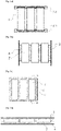
Fig. 2a ] représente un second mode de réalisation dans lequel les deux extrémités des éléments sont chacune maintenues par un flasque.[Fig. 2a ] shows a second embodiment in which the two ends of the elements are each held by a flange. -
[
Fig. 2b ] représente un troisième mode de réalisation dans lequel le matériau de calage est disposé d'une part entre les parois latérales d'éléments adjacents et entre la paroi latérale des éléments situés à la périphérie et la paroi interne d'une structure de maintien.[Fig. 2b ] shows a third embodiment in which the wedging material is placed on the one hand between the side walls of adjacent elements and between the side wall of the elements located at the periphery and the internal wall of a support structure. -
[
Fig. 2c ] représente un quatrième mode de réalisation dans lequel le matériau de calage est disposé entre les parois latérales de deux éléments adjacents et aux deux extrémités haute et basse des éléments.[Fig. 2c ] shows a fourth embodiment in which the wedging material is placed between the side walls of two adjacent elements and at the two upper and lower ends of the elements. -
[
Fig. 2d ] représente un cinquième mode de réalisation dans lequel les éléments sont alignés selon une direction définie par leur axe longitudinal. Les éléments sont placés dans un coffre de groupement de forme tubulaire.[Fig. 2d ] shows a fifth embodiment in which the elements are aligned in a direction defined by their longitudinal axis. The elements are placed in a tubular-shaped grouping box. -
[
Fig. 3 ] représente des courbes de densité spectrale de puissance DSP. Auxfigures 3a à 3d , l'élément testé est orienté tête en bas. La courbe A représente la DSP injectée. La courbe B représente la DSP rejectée.[Fig. 3 ] represents DSP power spectral density curves. Tofigures 3a to 3d , the tested element is oriented upside down. Curve A represents the injected DSP. The curve B represents the rejected DSP. -
La
figure 3a représente la densité spectrale de puissance pour des vibrations aléatoires appliquées dans une direction perpendiculaire à l'axe longitudinal de l'élément pour un matériau de calage constitué d'une résine polyuréthane.Thepicture 3a -
La
figure 3b représente la densité spectrale de puissance pour des vibrations aléatoires appliquées dans une direction selon l'axe longitudinal de l'élément pour un matériau de calage constitué d'une résine polyuréthane.Thefigure 3b represents the power spectral density for random vibrations applied in a direction along the longitudinal axis of the element for a cushioning material consisting of a polyurethane resin. -
La
figure 3c représente la densité spectrale de puissance pour des vibrations aléatoires appliquées dans une direction perpendiculaire à l'axe longitudinal de l'élément pour un matériau de calage constitué du gel de silicone 1.Thefigure 3c represents the power spectral density for random vibrations applied in a direction perpendicular to the longitudinal axis of the element for a cushioning material consisting ofsilicone gel 1. -
La
figure 3d représente la densité spectrale de puissance pour des vibrations aléatoires appliquées dans une direction selon l'axe longitudinal de l'élément pour un matériau de calage constitué du gel de silicone 1.The3d figure represents the power spectral density for random vibrations applied in a direction along the longitudinal axis of the element for a wedging material consisting ofsilicone gel 1. -
[
Fig. 4 ] représente des courbes de densité spectrale de puissance. Auxfigures 4a à 4d , l'élément est orienté tête en haut. La courbe A représente la DSP injectée. La courbe B représente la DSP rejectée.[Fig. 4 ] represents power spectral density curves. Tofigures 4a to 4d , the element is oriented head up. Curve A represents the injected DSP. Curve B represents the rejected DSP. -
La
figure 4a représente la densité spectrale de puissance pour des vibrations aléatoires appliquées dans une direction perpendiculaire à l'axe longitudinal de l'élément pour un matériau de calage constitué d'une résine polyuréthane.Thefigure 4a represents the power spectral density for random vibrations applied in a direction perpendicular to the longitudinal axis of the element for a cushioning material made of a polyurethane resin. -
La
figure 4b représente la densité spectrale de puissance pour des vibrations aléatoires appliquées dans une direction selon l'axe longitudinal de l'élément pour un matériau de calage constitué d'une résine polyuréthane.Thefigure 4b represents the power spectral density for random vibrations applied in a direction along the longitudinal axis of the element for a cushioning material consisting of a polyurethane resin. -
La
figure 4c représente la densité spectrale de puissance pour des vibrations aléatoires appliquées dans une direction perpendiculaire à l'axe longitudinal de l'élément pour un matériau de calage constitué du gel de silicone 2.Thefigure 4c represents the power spectral density for random vibrations applied in a direction perpendicular to the longitudinal axis of the element for a cushioning material consisting ofsilicone gel 2. -
La
figure 4d représente la densité spectrale de puissance pour des vibrations aléatoires appliquées dans une direction selon l'axe longitudinal de l'élément pour un matériau de calage constitué du gel de silicone 2.The4d figure represents the power spectral density for random vibrations applied in a direction along the longitudinal axis of the element for a wedging material consisting ofsilicone gel 2.
L'invention repose sur la découverte qu'un gel de silicone présentant une pénétrabilité allant de 20 à 500 unités, c'est-à-dire de 2 à 50 mm, peut être utilisé comme matériau de calage des éléments d'une batterie, la pénétrabilité étant mesurée par un test au cône entier tel que défini dans la norme NF ISO 2137 : 2020-11, pour un gel non travaillé. Le terme « non travaillé » signifie selon cette norme que la prise d'essai ayant servi pour la mesure de la pénétrabilité a subi le minimum de manipulations lors des opérations de transvasement du récipient porte-échantillon à la coupelle du malaxeur. Le choix de la plage spécifique de pénétrabilité de 20 à 500 unités conduit à un matériau offrant une protection contre les vibrations pour des hautes fréquences, par exemple supérieures à 100 Hz, voire supérieures à 1000 Hz, spécialement pour des vibrations appliquées dans le sens de l'axe longitudinal de l'élément, c'est-à-dire l'axe selon la plus grande dimension de l'élément. De telles valeurs de fréquences sont par exemple observées dans le cas d'un lancement d'un satellite. Au-delà de 500 unités de pénétrabilité, le matériau présente une cohésion insuffisante pour permettre un maintien des éléments. En deçà de 20 unités de pénétrabilité, le matériau présente une absorption insuffisante des vibrations. De préférence, la pénétrabilité du matériau va de 100 à 400 unités, de préférence de 200 à 300 unités, de préférence encore de 240 à 280 unités. Le matériau de calage permet un maintien des éléments en statique. On n'observe pas de fléchissement du matériau sous le poids des éléments.The invention is based on the discovery that a silicone gel having a penetrability ranging from 20 to 500 units, that is to say from 2 to 50 mm, can be used as wedging material for the elements of a battery, the penetrability being measured by a whole cone test as defined in standard NF ISO 2137: 2020-11, for an unworked gel. The term “unworked” means according to this standard that the test portion having been used for the measurement of the penetrability has undergone the minimum of manipulations during the operations of transfer from the sample holder container to the bowl of the mixer. The choice of specific range of penetrability from 20 to 500 units leads to a material offering protection against vibrations for high frequencies, for example higher than 100 Hz, even higher than 1000 Hz, especially for vibrations applied in the direction of the longitudinal axis of the element, i.e. the axis along the longest dimension of the element. Such frequency values are for example observed in the case of a satellite launch. Beyond 500 penetrability units, the material has insufficient cohesion to allow the elements to be maintained. Below 20 penetrability units, the material exhibits insufficient vibration absorption. Preferably, the penetrability of the material ranges from 100 to 400 units, preferably from 200 to 300 units, more preferably from 240 to 280 units. The wedging material allows the elements to be maintained statically. No deflection of the material under the weight of the elements is observed.
On entend par silicone un organopolysiloxane. Un organopolysiloxane est un polymère formé d'une chaîne principale inorganique constituée d'une répétition de liaisons siloxanes (...-Si-O-Si-...) sur laquelle des groupes organiques sont liés soit aux atomes de silicium et former ainsi une chaîne latérale, soit aux atomes de silicium situés aux extrémités de la chaîne principale. Le gel de silicone peut être obtenu par réticulation de deux polymères d'organopolysiloxane. Un gel de silicone convenant à l'invention est le gel de silicone BLUESIL ESA 6025 A&B commercialisé par la société Elkem. Fiche de données technique n° 6440-V14 - 2020/01/13.By silicone is meant an organopolysiloxane. An organopolysiloxane is a polymer formed from an inorganic main chain consisting of a repetition of siloxane bonds (...-Si-O-Si-...) on which organic groups are bonded either to silicon atoms and thus form a side chain, or to the silicon atoms located at the ends of the main chain. The silicone gel can be obtained by crosslinking two organopolysiloxane polymers. A silicone gel suitable for the invention is the BLUESIL ESA 6025 A&B silicone gel marketed by the company Elkem. Technical Data Sheet No. 6440-V14 - 2020/01/13.
La consistance du gel de silicone permet le démontage et le retrait des éléments en cas de soupçon d'anomalie de fonctionnement d'un ou de plusieurs éléments. L'effort déployé pour le démontage est bien inférieur à celui qui serait nécessaire si le matériau de calage était une résine polyuréthane rigide ou une résine époxyde. Les éléments défaillants peuvent être démontés, expertisés, réparés et réinstallés dans la batterie. La fluidité du matériau lui permet de combler tout l'espace entre l'élément et la structure de maintien. Le matériau peut être autocicatrisant, c'est-à-dire que des zones d'hétérogénéité à la surface du gel de silicone s'estompent spontanément pour conduire à une surface lisse. La fluidité du gel de silicone contribue au phénomène d'autocicatrisation.The consistency of the silicone gel allows the dismantling and removal of the elements in the event of a suspected malfunction of one or more elements. The effort expended for disassembly is much less than that which would be necessary if the wedging material were a rigid polyurethane resin or an epoxy resin. Faulty elements can be dismantled, appraised, repaired and reinstalled in the battery. The fluidity of the material allows it to fill all the space between the element and the support structure. The material can be self-healing, that is to say that areas of heterogeneity on the surface of the silicone gel fade spontaneously to lead to a smooth surface. The fluidity of the silicone gel contributes to the self-healing phenomenon.
Différents procédés peuvent être employés pour placer le matériau de calage entre la structure de maintien et un élément. La structure de maintien peut se présenter sous la forme d'une coupelle dont la section longitudinale est en forme de U et dont le diamètre interne est légèrement supérieur au diamètre du conteneur de l'élément. On vient déposer le gel de silicone dans le fond de la coupelle, puis on insère l'élément en direction du fond de la coupelle. Sous l'effet de la pression exercée sur le gel par l'enfoncement de l'élément, le gel de silicone s'étale dans le fond de la coupelle, remonte le long des parois verticales de la coupelle et vient combler l'espace entre la paroi verticale de la coupelle et l'élément.Various methods can be employed to place the wedging material between the supporting structure and an element. The retaining structure may be in the form of a cup, the longitudinal section of which is U-shaped and the internal diameter of which is slightly greater than the diameter of the container of the element. The silicone gel is deposited in the bottom of the cup, then the element is inserted towards the bottom of the cup. Under the effect of the pressure exerted on the gel by the depression of the element, the silicone gel spreads in the bottom of the dish, rises along the vertical walls of the dish and fills the space between the vertical wall of the cup and the element.
Quand l'espace entre deux éléments adjacents est suffisamment important, il est possible de faire couler le gel de silicone entre les deux éléments. Sous l'effet de la gravité, le gel vient combler l'espace entre les éléments. Enfin, un autre procédé consiste à introduire le gel à l'aide d'une seringue quand l'espace disponible est suffisamment important, par exemple dans l'espace entre deux éléments.When the space between two adjacent elements is large enough, it is possible to pour the silicone gel between the two elements. Under the effect of gravity, the gel fills the space between the elements. Finally, another method consists in introducing the gel using a syringe when the available space is large enough, for example in the space between two elements.
L'épaisseur du matériau une fois en place va en général de 1 à 10 mm, de préférence de 1 à 5 mm.The thickness of the material once in place generally ranges from 1 to 10 mm, preferably from 1 to 5 mm.
Différentes structures de maintien des éléments de la batterie vont maintenant être décrites. Ces structures sont décrites dans le cas d'un élément de format cylindrique. Néanmoins, l'invention ne se limite pas au calage d'éléments cylindriques mais s'étend à tout format d'éléments, par exemple prismatique. De préférence, les éléments de la batterie sont de type lithium-ion.Different structures for holding the elements of the battery will now be described. These structures are described in the case of a cylindrical format element. Nevertheless, the invention is not limited to the wedging of cylindrical elements but extends to any format of elements, for example prismatic. Preferably, the elements of the battery are of the lithium-ion type.
1) Un premier mode de réalisation est décrit en référence aux
2) Dans un second mode de réalisation, la structure de maintien est constituée d'un ou de deux flasques. Un flasque est un gabarit qui aide à maintenir en place la pluralité d'élements électrochimiques grâce à la présence d'évidements. Ces évidements s'emboitent avec (ou sont adaptés à recevoir) une portion de la surface du conteneur telle que le fond du conteneur ou un couvercle servant à obturer le conteneur. Les évidements sont pratiqués pour épouser soit la forme du couvercle, soit la forme du fond du conteneur. L'insertion par contact des éléments dans les flasques permet d'avoir un contact sur toute la section transversale des éléments, c'est-à-dire soit le fond du conteneur, soit une partie de la surface du couvercle, non occupée par les bornes de sortie de courant. L'espace entre le flasque et la section des éléments est comblé par le gel de silicone. Le gel de silicone peut permettre d'absorber les jeux éventuels existant entre un élément et le flasque. La périphérie des évidements des flasques peut présenter une épaisseur plus importante que le reste du flasque ou un joint à lèvre de manière à s'emboiter sur une portion de la longueur de la surface latérale du conteneur de l'élément ou sur une partie de l'épaisseur du couvercle de l'élément et ainsi garantir un très bon calage de l'élément. Plusieurs variantes sont possibles :
- un seul flasque maintenant en place la pluralité d'éléments par leur couvercle,
- un seul flasque maintenant en place la pluralité d'éléments par le fond de leur conteneur,
- deux flasques se faisant face, l'un maintenant en place la pluralité d'éléments par leur couvercle, l'autre maintenant en place la pluralité d'éléments par le fond de leur conteneur. Une telle variante est représentée sur la
figure 2a . Deux flasques 2-1 et 2-2 se font face. Le flasque 2-1 maintient l'une des extrémités des éléments tandis que le second flasque 2-2 maintient l'autre extrémité.
- a single flange holding the plurality of elements in place by their cover,
- a single flange holding the plurality of elements in place through the bottom of their container,
- two flanges facing each other, one holding in place the plurality of elements by their cover, the other holding in place the plurality of elements by the bottom of their container. Such a variant is represented on the
figure 2a . Two flanges 2-1 and 2-2 face each other. The flange 2-1 maintains one of the ends of the elements while the second flange 2-2 maintains the other end.
3) Dans un troisième mode de réalisation, les éléments sont maintenus uniquement par leurs parois latérales. Un tel mode de réalisation est illustré à la
4) Dans un quatrième mode de réalisation illustré à la
5) Dans un cinquième mode de réalisation illustré à la
Ces cinq modes de réalisation ont été illustrés aux
Outre les propriétés d'amortissement des vibrations à haute fréquence, spécialement dans la direction de l'axe longitudinal de l'élément, le gel de silicone présente les avantages suivants :
- il est isolant électrique. Sa constante diélectrique est d'environ 3 à 1 kHz selon la norme IEC 60250 ;
- il présente une tension de claquage élevée d'environ 20 kV/mm selon la norme IEC 60243 ;
- il ne se rétracte pas. Il s'expanse peu dans une gamme de températures proches de l'ambiante;
- il peut être utilisé en couche très fine, d'épaisseur inférieure à 2 mm, et également en couche épaisse ;
- il peut permettre un démontage des éléments. Les éléments peuvent être réutilisés hors de la batterie ;
- il n'endommage pas les traitements de surface, ni les peintures ;
- il ne présente pas de risque pour la santé, contrairement aux résines polyuréthanes qui ont des effets cancérogènes, mutagènes ou sont toxiques pour la reproduction (CMR).
- it is an electrical insulator. Its dielectric constant is approximately 3 to 1 kHz according to the IEC 60250 standard;
- it has a high breakdown voltage of around 20 kV/mm according to standard IEC 60243;
- he does not retract. It expands little in a range of temperatures close to ambient;
- it can be used in a very thin layer, with a thickness of less than 2 mm, and also in a thick layer;
- it can allow elements to be dismantled. Cells can be reused out of the battery;
- it does not damage surface treatments or paints;
- it does not pose a health risk, unlike polyurethane resins which have carcinogenic, mutagenic or reproductive toxic effects (CMR).
Le matériau de calage peut être utilisé pour caler les éléments d'une batterie destinée à être utilisée dans un moyen de transport terrestre, un moyen de transport routier, un moyen de transport ferroviaire, un moyen de transport maritime ou fluvial, un aéronef, un chariot de manutention.The cushioning material can be used to cushion the elements of a battery intended to be used in a means of land transport, a means of road transport, a means of rail transport, a means of maritime or river transport, an aircraft, a truck.
Il peut être utilisé dans une batterie destinée à alimenter certains dispositifs tels qu'un satellite à basse orbite terrestre (LEO) et un satellite géostationnaire (GEO). Il peut être utilisé dans des applications pétrolières (alimentation de capteurs placés dans une tête de forage).It can be used in a battery intended to power certain devices such as a low earth orbit (LEO) satellite and a geostationary (GEO) satellite. It can be used in oil applications (supply of sensors placed in a drilling head).
Un élément lithium-ion de format cylindrique a été calé par du gel de silicone dans une structure de maintien selon le premier mode de réalisation illustré aux
L'objectif a été de déterminer avec un balayage sinus, les fréquences auxquelles on repère une augmentation du signal rejecté par rapport au signal injecté. Cette augmentation correspondant à une amplification du signal. Les fréquences, auxquelles une amplification du signal apparaît, sont appelées fréquences de résonance F. L'amplification Q est définie comme la racine carrée du rapport entre la densité spectrale de puissance réjectée et la densité spectrale de puissance injectée à la fréquence de résonance.The objective was to determine with a sine sweep, the frequencies at which an increase in the rejected signal is detected compared to the injected signal. This increase corresponds to an amplification of the signal. The frequencies, at which an amplification of the signal appears, are called resonance frequencies F. The amplification Q is defined as the square root of the ratio between the spectral density of rejected power and the spectral density of injected power at the resonant frequency.
Critères de succès :Success criteria:
- La première fréquence à laquelle est mesurée une amplification doit être supérieure à 140 Hz.The first frequency at which an amplification is measured must be greater than 140 Hz.
- L'amplification à la fréquence de résonance doit être inférieure voire comparable à une résine polyuréthane avec confirmation de la non-dégradation des éléments.The amplification at the resonance frequency must be lower or even comparable to a polyurethane resin with confirmation of the non-degradation of the elements.
Profil :
La recherche de fréquence se fait par un balayage sinus à 2 octaves par minute selon le tableau 1:
The frequency search is done by a sine sweep at 2 octaves per minute according to table 1:
Les résultats sont donnés dans le tableau 2 ci-dessous, avec en comparaison les résultats obtenus sur la résine polyuréthane.
On constate que le gel 1 et le gel 2 satisfont le critère d'une fréquence de résonance supérieure à 140 Hz.It can be seen that
Les tests de vibrations sinus réalisés avec le gel 1 et le gel 2 conduisent à des résultats équivalents à ceux obtenus avec la résine polyuréthane.Sinus vibration tests carried out with
Les niveaux de vibrations appliqués à l'élément, en fonction de la fréquence sont donnés dans le Tableau 3.
Les niveaux de vibration appliqués sont représentés sur une courbe DSP en fonction de la fréquence de la vibration (Hz). Les courbes DSP ont été tracées pour un élément orienté tête en bas, pour un matériau de calage constitué soit de la résine polyuréthane, soit du gel de silicone 1. Dans le cas de la résine polyuréthane, on note une amplification de la DSP sur quasiment toute la plage de fréquences balayée, que ce soit dans la direction de l'axe longitudinal ou dans une direction perpendiculaire à l'axe longitudinal de l'élément. En effet, la DSP rejectée (B) est au-dessus de la DSP (A) sur quasiment toute la gamme de fréquences balayées (
Les courbes DSP ont été tracées pour un élément orienté tête en haut, pour un matériau de calage constitué soit de la résine polyuréthane, soit du gel de silicone 2. Dans le cas de la résine polyuréthane, on note une amplification de la DSP de 70 à 700 Hz, dans la direction perpendiculaire à l'axe longitudinal de l'élément et à partir de 400 Hz dans la direction de l'axe longitudinal de l'élément (
Le paramètre GRMS correspond à l'accélération globale moyennée (racine de l'intégrale de la DSP par la fréquence qui est l'aire sous la courbe DSP) sur la plage complète des fréquences balayées, c'est-à-dire allant de 20 à 2000 Hz. L'exploitation des courbes DSP des
Dans le cas du gel de silicone 1 « tête en bas », la valeur de GRMS est inférieure de 30% à celle de la résine polyuréthane dans la direction perpendiculaire à l'axe longitudinal de l'élément (20,6 vs. 29,5). La valeur du GRMS est inférieure de 82% à celle de la résine polyuréthane dans la direction de l'axe longitudinal de l'élément (8,5 vs. 46,9). Dans la direction de l'axe longitudinal de l'élément, la valeur de GRMS réjecté est même inférieure à celle de GRMS injecté (8,5 vs. 17,3).In the case of
Dans le cas du gel de silicone 2 « tête en haut », la valeur de GRMS est équivalente à celle de la résine polyuréthane dans la direction perpendiculaire à l'axe longitudinal de l'élément. La valeur du GRMS est inférieure de 36 % à celle de la résine polyuréthane dans la direction de l'axe longitudinal de l'élément (15,6 vs. 24,2). Dans la direction de l'axe longitudinal de l'élément, la valeur de GRMS réjecté est même inférieure à celle de GRMS injecté (15,5 vs. 17,3). Les gels 1 et 2 réduisent donc la DSP dans la direction de l'axe longitudinal de l'élément.In the case of “head-up”
L'accélération gamma à la fréquence de résonance est définie selon la formule de Miles suivante :
- F est la fréquence de résonance mesurée lors des vibrations aléatoires ;
- P est la densité spectrale de puissance exprimée en g2/Hz à la fréquence de résonance ;
- Q est l'amplification à la fréquence de résonance F et se définit comme la racine carrée du ratio entre la DSP rejectée (Pmax en g2/Hz) et la DSP injectée.

- F is the resonance frequency measured during random vibrations;
- P is the power spectral density expressed in g 2 /Hz at the resonance frequency;
- Q is the amplification at the resonance frequency F and is defined as the square root of the ratio between the rejected PSD (Pmax in g 2 /Hz) and the injected PSD.
Les tableaux 5 et 6 indiquent les valeurs du paramètre γ de la formule de Miles pour les orientations tête en haut et tête en bas de l'élément.
Les tableaux 5 et 6 montrent que les accélérations γ à la fréquence de résonance pour les gels 1 et 2 sont inférieures à celles de la résine de polyuréthane.Tables 5 and 6 show that the γ accelerations at the resonant frequency for
Claims (10)
Applications Claiming Priority (1)
| Application Number | Priority Date | Filing Date | Title |
|---|---|---|---|
| FR2103072A FR3121285B1 (en) | 2021-03-26 | 2021-03-26 | Wedging material for electrochemical elements in a battery |
Publications (1)
| Publication Number | Publication Date |
|---|---|
| EP4071908A1 true EP4071908A1 (en) | 2022-10-12 |
Family
ID=76730671
Family Applications (1)
| Application Number | Title | Priority Date | Filing Date |
|---|---|---|---|
| EP22163573.3A Pending EP4071908A1 (en) | 2021-03-26 | 2022-03-22 | Material for wedging of electrochemical elements in a battery |
Country Status (2)
| Country | Link |
|---|---|
| EP (1) | EP4071908A1 (en) |
| FR (1) | FR3121285B1 (en) |
Citations (7)
| Publication number | Priority date | Publication date | Assignee | Title |
|---|---|---|---|---|
| JPH08106886A (en) * | 1994-10-03 | 1996-04-23 | Asahi Chem Ind Co Ltd | Battery |
| US20050095499A1 (en) * | 2001-12-28 | 2005-05-05 | Hideyuki Kanai | Battery pack and rechargeable vacuum cleaner |
| EP2403050A1 (en) | 2010-07-02 | 2012-01-04 | Saft | Battery of electrochemical generators including a foam as a filling material between generators |
| CN108023039A (en) * | 2017-10-19 | 2018-05-11 | 惠州时代电池有限公司 | Battery assembly |
| KR20190091631A (en) * | 2018-01-29 | 2019-08-07 | 주식회사티움리서치 | Vibration resistant battery cell holder and battery pack with the same |
| WO2020094365A1 (en) | 2018-11-05 | 2020-05-14 | Xerotech Limited | A battery pack and a method of manufacturing a battery pack |
| US20200203679A1 (en) * | 2018-12-25 | 2020-06-25 | Honda Motor Co.,Ltd. | Cell structure of solid state battery and manufacturing method of solid state battery |
-
2021
- 2021-03-26 FR FR2103072A patent/FR3121285B1/en active Active
-
2022
- 2022-03-22 EP EP22163573.3A patent/EP4071908A1/en active Pending
Patent Citations (8)
| Publication number | Priority date | Publication date | Assignee | Title |
|---|---|---|---|---|
| JPH08106886A (en) * | 1994-10-03 | 1996-04-23 | Asahi Chem Ind Co Ltd | Battery |
| US20050095499A1 (en) * | 2001-12-28 | 2005-05-05 | Hideyuki Kanai | Battery pack and rechargeable vacuum cleaner |
| EP2403050A1 (en) | 2010-07-02 | 2012-01-04 | Saft | Battery of electrochemical generators including a foam as a filling material between generators |
| CN108023039A (en) * | 2017-10-19 | 2018-05-11 | 惠州时代电池有限公司 | Battery assembly |
| KR20190091631A (en) * | 2018-01-29 | 2019-08-07 | 주식회사티움리서치 | Vibration resistant battery cell holder and battery pack with the same |
| WO2020094365A1 (en) | 2018-11-05 | 2020-05-14 | Xerotech Limited | A battery pack and a method of manufacturing a battery pack |
| WO2020094364A1 (en) * | 2018-11-05 | 2020-05-14 | Xerotech Limited | A duct and a method of manufacturing a duct |
| US20200203679A1 (en) * | 2018-12-25 | 2020-06-25 | Honda Motor Co.,Ltd. | Cell structure of solid state battery and manufacturing method of solid state battery |
Non-Patent Citations (2)
| Title |
|---|
| ANONYMOUS: "Accelerate your transportation revolution with Electronic Silicone Solutions", ELKEM, 1 January 2018 (2018-01-01), pages 1 - 24, XP093074644, Retrieved from the Internet <URL:https://www.hisco.com/userfiles/images/landingpages/elkem/elkememobility/ev_2020_brochure_electronic_vehicles.pdf> [retrieved on 20230817] |
| ANONYMOUS: "SILICONE GEL SOLUTIONS", WACKER CHEMIE AG, 1 September 2016 (2016-09-01), pages 1 - 16, XP093074649, Retrieved from the Internet <URL:https://www.wacker.com/h/medias/6982-EN.pdf> [retrieved on 20230817] |
Also Published As
| Publication number | Publication date |
|---|---|
| FR3121285A1 (en) | 2022-09-30 |
| FR3121285B1 (en) | 2023-03-03 |
Similar Documents
| Publication | Publication Date | Title |
|---|---|---|
| EP3208866B1 (en) | System to compensate for the swelling of electrochemical elements | |
| EP2403050B1 (en) | Battery of electrochemical generators including a foam as a filling material between generators | |
| FR3116657A1 (en) | Metal-ion accumulator fitted with a degassing duct, Battery module or Battery pack associated with liquid cooling. | |
| CA3000587A1 (en) | Electrical energy storage module and method for producing same | |
| WO2015097281A1 (en) | Electrochemical battery with improved operating safety in moist environments | |
| EP4071908A1 (en) | Material for wedging of electrochemical elements in a battery | |
| FR3119939A1 (en) | Battery module | |
| WO2014131875A1 (en) | Safety device for a battery of lithium electrochemical generators | |
| EP3087624A1 (en) | Electrochemical battery module having improved resistance in moist environments and method for producing at least one such module | |
| EP3155270B1 (en) | Means for wedging an electrochemical generator in position in a battery | |
| EP3662972B1 (en) | Implantable medical device with improved architecture | |
| FR2601819A1 (en) | ELECTROCHEMICAL CELL AND METHOD FOR MANUFACTURING THE SAME | |
| EP3948905A1 (en) | Capacitive block comprising a spacer | |
| EP4564538B1 (en) | Battery module with at least one battery including phase change metal powder to limit thermal runaway propagation and pressure increase therefor | |
| FR3121265A1 (en) | UNIT FOR THE TRANSPORT OF URANIUM HEXAFLUORIDE | |
| EP4468438A1 (en) | Method for producing a lithium-metal or sodium-metal all-solid battery from a liquid electrolyte metal-ion electrochemical battery for thermal mist testing | |
| FR3150046A1 (en) | Battery pack comprising a heat transfer fluid capable of containing the thermal runaway of the electrochemical accumulators of the battery pack | |
| WO2024033575A1 (en) | Packaging, package having such packaging, use of such packaging, mixing device, and method for loading and/or unloading | |
| EP4092796A1 (en) | Battery module | |
| WO2026008946A1 (en) | Thermal management device for an electric battery | |
| FR3136116A1 (en) | BATTERY PACK WITH FIRE SPREAD DELAY DEVICE | |
| FR3001338A1 (en) | BATTERY MODULE AND METHOD OF MANUFACTURE | |
| CN121983728A (en) | Battery compartment structure of node instrument and pouring sealant method thereof | |
| FR3121264A1 (en) | SET FOR THE TRANSPORT OF URANIUM HEXAFLUORIDE, INCLUDING SHOCK ABSORBING COVERS | |
| WO2022106426A1 (en) | Electrochemical pouch cell for energy storage device |
Legal Events
| Date | Code | Title | Description |
|---|---|---|---|
| PUAI | Public reference made under article 153(3) epc to a published international application that has entered the european phase |
Free format text: ORIGINAL CODE: 0009012 |
|
| STAA | Information on the status of an ep patent application or granted ep patent |
Free format text: STATUS: THE APPLICATION HAS BEEN PUBLISHED |
|
| AK | Designated contracting states |
Kind code of ref document: A1 Designated state(s): AL AT BE BG CH CY CZ DE DK EE ES FI FR GB GR HR HU IE IS IT LI LT LU LV MC MK MT NL NO PL PT RO RS SE SI SK SM TR |
|
| STAA | Information on the status of an ep patent application or granted ep patent |
Free format text: STATUS: REQUEST FOR EXAMINATION WAS MADE |
|
| 17P | Request for examination filed |
Effective date: 20230412 |
|
| RBV | Designated contracting states (corrected) |
Designated state(s): AL AT BE BG CH CY CZ DE DK EE ES FI FR GB GR HR HU IE IS IT LI LT LU LV MC MK MT NL NO PL PT RO RS SE SI SK SM TR |
|
| P01 | Opt-out of the competence of the unified patent court (upc) registered |
Effective date: 20230514 |
|
| TPAC | Observations filed by third parties |
Free format text: ORIGINAL CODE: EPIDOSNTIPA |
|
| STAA | Information on the status of an ep patent application or granted ep patent |
Free format text: STATUS: EXAMINATION IS IN PROGRESS |
|
| 17Q | First examination report despatched |
Effective date: 20241004 |