EP2401221B1 - Aufzug mit einem überwachungssystem - Google Patents
Aufzug mit einem überwachungssystem Download PDFInfo
- Publication number
- EP2401221B1 EP2401221B1 EP10704944.7A EP10704944A EP2401221B1 EP 2401221 B1 EP2401221 B1 EP 2401221B1 EP 10704944 A EP10704944 A EP 10704944A EP 2401221 B1 EP2401221 B1 EP 2401221B1
- Authority
- EP
- European Patent Office
- Prior art keywords
- microprocessor
- code
- control unit
- switch
- bus
- Prior art date
- Legal status (The legal status is an assumption and is not a legal conclusion. Google has not performed a legal analysis and makes no representation as to the accuracy of the status listed.)
- Active
Links
- 238000012544 monitoring process Methods 0.000 title description 32
- 230000006698 induction Effects 0.000 claims description 16
- 238000000034 method Methods 0.000 claims description 7
- 230000008054 signal transmission Effects 0.000 claims description 7
- 239000004020 conductor Substances 0.000 description 39
- 238000012360 testing method Methods 0.000 description 24
- 230000002093 peripheral effect Effects 0.000 description 14
- 238000011156 evaluation Methods 0.000 description 9
- 230000005540 biological transmission Effects 0.000 description 5
- 230000004044 response Effects 0.000 description 4
- 230000002269 spontaneous effect Effects 0.000 description 4
- 230000008034 disappearance Effects 0.000 description 3
- 230000006870 function Effects 0.000 description 3
- 230000009118 appropriate response Effects 0.000 description 1
- 239000000969 carrier Substances 0.000 description 1
- 230000009351 contact transmission Effects 0.000 description 1
- 230000001419 dependent effect Effects 0.000 description 1
- 230000005674 electromagnetic induction Effects 0.000 description 1
- 238000009434 installation Methods 0.000 description 1
- 238000012423 maintenance Methods 0.000 description 1
- 230000007257 malfunction Effects 0.000 description 1
- 230000000737 periodic effect Effects 0.000 description 1
Images


Classifications
-
- B—PERFORMING OPERATIONS; TRANSPORTING
- B66—HOISTING; LIFTING; HAULING
- B66B—ELEVATORS; ESCALATORS OR MOVING WALKWAYS
- B66B13/00—Doors, gates, or other apparatus controlling access to, or exit from, cages or lift well landings
- B66B13/22—Operation of door or gate contacts
Definitions
- the invention relates to an elevator with a monitoring system according to the preamble of the independent claims.
- WO03 / 107295 A1 shows a monitoring system for status monitoring of peripheral devices, for example elevator components.
- the bus system has a bus, a central control unit connected to the bus and several peripheral devices. Each of these devices is located at a bus node and communicates with the control unit via the bus. At any point in time, the peripheral devices assume a specific status.
- the control unit periodically polls the status of each peripheral device via the bus.
- the bus is powered by the control unit and supplies electromagnetic induction loops that are part of a bus node.
- the individual peripheral devices are coupled via a local antenna to the induction loops of the bus nodes and receive electromagnetic energy through the associated induction loop. Via the induction loop, the peripheral device also informs the control unit of its identification code as well as its current status. Thanks to this identification code, the control unit can assign the read status to a particular peripheral device.
- a disadvantage is the periodic polling of the status of the peripheral devices via the bus. Since the control unit actively polls each peripheral device, the bus transmits two signals per poll and peripheral device. With relatively short polling cycles, especially with safety-related peripheral devices, and a relatively high number of such devices, a large number of signals are exchanged between the control unit and the peripheral devices. This means that the control unit has high computing capacity to process all signals. In addition, the bus is heavily loaded and provides high signal transmission capacity to convey all status requests. Accordingly, the control unit and the bus are expensive.
- the elevator has a control unit, a bus, at least a first microprocessor and a second microprocessor, which are assigned to a bus node and which are connected via the bus to the control unit.
- the elevator is characterized in that the control unit transmits an instruction via the bus to the second microprocessor to interrupt a signal transmission to the first microprocessor, so that the first microprocessor sends a status message to the control unit.
- the advantage of this elevator lies in the simple and reliable checking of the functionality of the first microprocessor.
- the spontaneous response of the first microprocessor is provoked by the second microprocessor interrupts the transmission of the state signal to the first microprocessor, thus simulating the occurrence of a dangerous state, for example.
- At least one code-carrying element and at least one code-reading element are assigned to the bus node in the elevator.
- the code reading element non-contactly reads an identification code from the code carrying element and sends a signal to the first microprocessor.
- the code-carrying element and the code-reading element each have an induction loop.
- the code-reading element supplies the code-carrying element by means of the two induction loops contactlessly with electromagnetic energy.
- the code-carrying element transmits its identification code by means of the two induction loops contactlessly to the code-reading element.
- the sensor components used comprising the code-carrying and the code-reading element hardly exploit during operation. This can reduce maintenance costs and increase surveillance security.
- code-carrying and code-reading elements for example, in the embodiment as passive or active RFID system available as a mass product and extremely cheap.
- the code-reading element transmits the signal by means of a data conductor to at least the first microprocessor.
- the second microprocessor actuates a switch for interrupting the data conductor or a switch for interrupting a power supply of the code-reading element.
- the control unit confirms the status message of the first microprocessor due to the interruption of the signal transmission by the second microprocessor.
- control unit can not confirm the provoked status message of the first microprocessor, it can be assumed that at least the first or second microprocessor has a malfunction and the condition monitoring is no longer secure.
- the advantage of this test is that a continuous polling of the state signals received by the first microprocessor by the control unit is eliminated. As long as the functionality of the first microprocessor is detected by the control unit, it is sufficient if the first microprocessor transmits a status message to the control unit only when a potentially dangerous condition of the elevator occurs. This reduces the number of signals to be processed. So cheaper buses and tax units can be used.
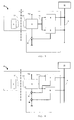
- Fig. 1 shows a first embodiment of the monitoring system, as used for example in an elevator.
- a control unit 10 is connected to a bus 9.
- the control unit 10 communicates via the bus 9 with at least one bus node 30.
- the control unit 10, the bus 9 and the at least one bus node 30 form a Bus system.
- each bus node 30 has a unique identifiable address. By means of this address signals from the control unit 10 can be selectively transmitted to a specific bus node 30.
- incoming signals are uniquely assignable to a bus node 30.
- data can be sent in both directions via the bus 9 between the bus node 30 and the control unit 10.
- the two microprocessors 4 and 5 are designed such that the first microprocessor 4 transmits at least status information to the control unit 10 and the second microprocessor 5 receives at least control commands of the control unit 10.
- the two microprocessors 4, 5 are configurable both physically and virtually. In the case of two physically configured microprocessors 4, 5, for example, two microprocessors 4, 5 are arranged on a die. In an alternative embodiment, the two microprocessors 4, 5 can each realize their own die. However, physically only one microprocessor 4 may be present. In this case, a second microprocessor 5 is virtually configurable by software on the first physically present microprocessor 4.
- the bus node 30 further has at least one code-carrying element 1 and a code-reading element 3.
- the code-carrying element 1 is an RFID tag 1 and the code-reading element 3 is an RFID system 3.
- Both the RFID tag 1 and the RFID system 3 each have an induction loop 2.1, 2.2.
- the RFID system 3 supplies the RFID tag 1 with electromagnetic energy by means of these induction loops 2.1, 2.2.
- the RFID system 3 is connected to a power source Vcc.
- the power source preferably supplies the RFID system 3 with either electrical or electrical power.
- the RFID tag 1 transmits via the induction loops 2.1, 2.2 an identification code stored on the RFID tag 1 to the RFID system 3.
- the power supply Vcc of the RFID tag 1 is only ensured if the RFID tag 1 is in spatial proximity below a critical distance to the RFID system 3 and the induction loop 2.1 of the RFID tag 1 can be excited by the induction loop 2.2 of the RFID system 3.
- the power supply Vcc of the RFID tag 1 thus functions only below a critical distance to the RFID system 3. If the critical distance is exceeded, the RFID tag 1 does not receive enough energy to maintain the transmission of the identification code to the RFID system 3 receive.
- the RFID system 3 is connected via a data conductor 6 to the first microprocessor 4 and transmits the received identification code to this first microprocessor 4.
- the microprocessor 4 compares the identification code with a stored on a memory unit list of identification codes. In this comparison, the microprocessor 4 calculates a status value according to stored rules in dependencies of the identification code. This status value can assume a positive or a negative value. A negative status value is generated, for example, if no identification code or a wrong identification code is transmitted to the microprocessor 4.
- the microprocessor 4 sends a signal via the bus 9 to the control unit 10.
- This signal contains at least the address of the bus node 30 and preferably the identification code of the detected RFID tag 1. Thanks to the communicated address, the control unit 10 is in the Able to locate the origin of the negative status value and initiate an appropriate response.
- bus node 30 monitors the status of a hoistway door.
- the RFID tag 1 and the RFID system 3 are arranged in the area of the shaft doors so that when the shaft door is closed, the distance between the RFID tag 1 and the RFID system 3 is below the critical distance.
- the microprocessor 4 thus receives the identification code from the RFID system 3 and generates a positive status value. If the hoistway door is opened, the RFID tag 1 and the RFID system 3 exceed the critical distance. Since the RFID tag 1 is no longer supplied with electrical energy by the RFID system 3, the RFID tag 1 stops sending its identification code and the microprocessor 4 generates a negative status value. Accordingly, the microprocessor 4 sends a signal of the control unit 10.
- the control unit located thanks to the address of the bus node 30, the open shaft door. If this shaft door is unauthorized open, for example, there is no elevator car in the shaft door area, the control unit 10 initiates a reaction to bring the elevator in a safe state.
- bus node 30 The safe operation of a bus node 30 depends primarily on the functionality of the microprocessor 4. Therefore, a bus node 30 is regularly tested by the control unit 10 to check the spontaneous transmission behavior of the microprocessor 4 when a negative status value occurs.
- the control unit 10 sends a control command via the bus 9 to a second microprocessor 5 to open a switch 31.
- This switch 31 interrupts the data conductor 6 between the RFID system 3 and the first microprocessor 4.
- the microprocessor 4 receives no identification code and generates a negative status value. So a "disappearance" of the RFID tag 1 is simulated. If the microprocessor 4 functions perfectly, it will spontaneously respond to the control unit 10.
- This test is performed in a timely manner for each bus node 30. Since during this test the control unit 10 can not detect any real information about the status of the tested bus node 30, the test time is kept as short as possible and the test is performed only as often as necessary. The test time is largely dependent on the speed of data transmission via the bus 9 and the response time of the microprocessors 4, 5 and is usually 1 to 100 ms. The frequency of the test depends primarily on the failure probability of the entire system. The more reliable the overall system, the less frequently can it be tested so that reliable status monitoring of an elevator component is ensured.
- the test is carried out at least once a day. This test can also be repeated in the order of hours or minutes.
- bus node 30 In the following, further embodiments of the monitoring system, in particular of the bus node 30 will be described. Since the basic structure of the bus node 30 and the operation of the bus components 1 to 5 are comparable in these embodiments, only the differences in the structure and operation of the different bus node 30 will be discussed.
- Fig. 2 shows a second embodiment of the monitoring system.
- the second microprocessor 5 actuates a switch 32 when testing the bus node 30.
- the switch 32 is open, the power supply Vcc of the RFID system 3 is interrupted.
- the power source Vcc is turned off, the RFID system 3 sets the transmission of the identification code signal via the data conductor 7 to the microprocessor 4 a.
- Fig. 3 shows a third embodiment of the monitoring system.
- the second microprocessor 5 actuates a switch 33 when testing the first microprocessor 4.
- this switch 33 connects the RFID system 3 to the first microprocessor 4 via the data conductor 8 and the two microprocessors 4 and 2 in a second switch position 5 by means of another data conductor 90.
- the advantage of this embodiment is that not only a "disappearance" of the RFID tag 1 can be simulated, but that the second microprocessor 5 can also specify different identification codes. This is particularly important if several RFID tags 1 with different identification codes can reach the reception area of the RFID system 3. Depending on which identification code the second microprocessor 4 reads, this generates a positive or negative status value.
- Fig. 4 shows a fourth embodiment of the monitoring system.
- the identification code signal is redundantly detected and evaluated via the data conductor 11 by the two microprocessors 4, 5. If, therefore, at least one of the two microprocessors 4, 5 generates a negative status value, the bus node 30 transmits a signal to the control unit 10.
- An advantage of this fourth embodiment is the redundant and therefore very reliable evaluation of the identification code.
- a microprocessor 4, 5 interrupts the data conductor 11 between the RFID system 3 and the other microprocessor 5, 4 by means of a switch 34 or 35.
- the switch 34, 35 actuated microprocessor 4, 5 continue the real identification code of the RFID tag 1.
- the bus node 30 thus continues to be able to send a real status signal to the control unit 10.
- the control unit 10 therefore detects during the test actually occurring negative status messages of a microprocessor 4, 5. In such a case, as expected, only a negative status message provoked by the test, but the bus node 30 would transmit two status signals to the control unit 10, a virtual and a real status. In the expectation of only one status signal, in this case, the control unit 10 recognizes that the bus node 30 has a real negative status.
- FIGS. 5 and 6 show a fifth and a sixth embodiment of the monitoring system.
- the identification code signal is likewise evaluated redundantly by the two microprocessors 4, 5 via a data conductor 12 or 13.
- the control unit 10 when testing the bus node 30, the control unit 10 sends a control command to open a switch 36 to the second microprocessor 5. In the open position of the switch 36, the power supply Vcc to the RFID system 3 is interrupted. In the sixth embodiment, however, can be the Power supply Vcc of the RFID system 3 by two switches 37 and 38 interrupt, which are respectively switched by the second and first microprocessor 5, 4. In the absence of the identification code signal, both the first and the second microprocessor 4, 5 of the control unit 10 send a corresponding signal.
- the identification code signals read by the RFID systems 3a, 3b are transmitted to at least one of the microprocessors 4, 5 by means of different data conductor arrangements. Furthermore, different switch arrangements for testing the bus node 30 are shown.
- the bus node 30 has two RFID systems 3a, 3b which each supply an RFID tag 1a, 1b by means of an induction loop pair 2.1a, 2.2a, 2.1b, 2.2b with electrical energy and that of the RFID tags 1a, 1b received received identification codes.
- Bus nodes 30 which have two RFID systems 3a, 3b or RFID tags 1a, 1b can either monitor the status of an elevator element redundantly or monitor two different statuses of preferably spatially adjacent elevator elements. Accordingly, in a lift installation, for example by means of two RFID systems 3a, 3b and two RFID tags 1a, 1b, the status of a shaft door can be monitored redundantly or two states of a car door and also an alarm button likewise positioned on an elevator car can be monitored.
- the two RFID systems 3a, 3b transmit the detected identification code via a respective data line 14, 15, 16, 17, 18, 19 to a microprocessor 4, 5.
- Fig. 7 shows a bus node 30, whose functionality is performed by means of mutual interruption of the data line 14, 15 by means of a switch 39, 40.
- a first microprocessor 4 receives from the control unit 10 the instruction to interrupt the data conductor 15 to the second microprocessor 5 by means of switch 40 and the second microprocessor 5 receives from the control unit 10 the instruction to interrupt the data conductor 14 to the first microprocessor 4 by means of switch 39.
- Fig. 8 In contrast to the embodiment of Fig. 7 will be in the Fig. 8 and 9 the spontaneous response of the microprocessors 4, 5 provoked by interrupting the respective power supply Vcca, Vccb to an RFID system 3a, 3b.
- the control unit 10 each has a first microprocessor 4, 5 to open a switch 41, 42 for power supply Vcca, Vccb of the second microprocessor 5, 4 connected RFID system 3b, 3a and vice versa.
- both microprocessors 4, 5 actuate the same switch 43, which interrupts the supply of the power supply Vcc to both RFID systems 3a, 3b. If, for example, the first microprocessor 4 opens the switch 43, not only the second microprocessor 5 spontaneously reports to the control unit 10, but also the first microprocessor 4. Likewise, both microprocessors 4, 5 report to the control unit 10 when the switch 43 from the second Microprocessor 5 is operated.
- Fig. 10 shows an embodiment in which two RFID systems 3a, 3b transmit their identification code by means of a data conductor 20 to a first microprocessor 4.
- a second microprocessor 5 tests the operability of the first microprocessor 4. In this test, the second microprocessor 5 actuates a switch 44 and thus interrupts the data conductor 20.
- the second microprocessor 5 interrupts the power supply Vcc of the switch 74 both RFID systems 3a, 3b.
- This alternative test arrangement is in Fig. 10 shown with dotted lines.
- Embodiments of surveillance systems are also shown, which have two RFID systems 3a, 3b, which each supply an RFID tag 1a, 1b with energy and read their identification code.
- the evaluation of the read identification codes takes place redundantly, since the two RFID systems transmit the respectively read identification code via a data conductor 21, 22, 23, 24, 25, 26 both to the first microprocessor 4 and to the second microprocessor 5.
- the bus node 30 according to one of these three embodiments is tested in different ways.
- the first microprocessor 4 controls a switch 47 for opening the data conductor 22 between the second microprocessor 5 and the two RFID systems 3a, 3b.
- the spontaneous response of the microprocessor 5 is tested.
- the second microprocessor 5 in turn opens when testing the first microprocessor 4 means of another switch 46, the data conductor 21 between the first microprocessor 4 and the RFID systems 3a, 3b and causes it to send a signal to the control unit 10.
- the power supply Vcc of the RFID systems 3a, 3b is interrupted by means of a switch 48.
- This switch is in each case actuated by one of the microprocessors 4, 5.
- both microprocessors 4, 5 transmit a signal to the control unit 10.
- Fig. 13 is different from the one of Fig. 12 in that the RFID systems 3a, 3b each have their own power supply Vcca and Vccb. Furthermore, each of these power supplies Vcca, Vccb can be switched off individually by a separate switch 49, 50. This is done in each case by one of the microprocessors 4, 5 Fig. 13 For example, the microprocessor 4 switches the switch 50 of the power supply Vccb and the microprocessor 5 switches the switch 49 of the power supply Vcca.
- microprocessors 4, 5 function properly, they will be reported simultaneously upon actuation of a switch 49, 50, because, for example, the interruption of the power supply Vcca will cause the RFID system 3a to fail and, accordingly, the identification code to neither the first microprocessor 4 nor the second microprocessor 5 is transmitted by means of the data conductors 25, 26.
- the Fig. 14 and 15 represent further embodiments of the monitoring system.
- a switch 51 In the first embodiment according to Fig. 14 actuates the second microprocessor 5 in the test of the first microprocessor 4, a switch 51.
- This switch 51 connect in a first switch position the RFID systems 3a, 3b by means of the data conductor 27 with the first microprocessor 4 and in a second switch position, the two microprocessors 4 and 5 by means of another data conductor 91.
- the embodiment according to FIG. 15 actuates in each case one of the two microprocessors 4, 5 a switch 52, 53 which connects the RFID systems 3a, 3b by means of a data conductor 28, 29 with the other microprocessor 5, 4 in a first switch position.
- a second switch position in each case one microprocessor 4, 5 is connected to the other microprocessor 5, 4 by means of a respective further data conductor 92, 93.
- the advantage of these two embodiments is that not only a disappearance of the RFID tags 1a, 1b can be simulated, but that the switch operating microprocessor 4, 5 can also specify different identification codes to the other microprocessor 5, 4. This is particularly important if several RFID tags 1a, 1b with different identification codes can reach the reception area of the RFID systems 3a, 3b. Depending on which identification code is read by the first or second microprocessor 4, 5, a positive or negative status values is generated.
Landscapes
- Indicating And Signalling Devices For Elevators (AREA)
- Control By Computers (AREA)
- Elevator Control (AREA)
- Remote Monitoring And Control Of Power-Distribution Networks (AREA)
Priority Applications (2)
| Application Number | Priority Date | Filing Date | Title |
|---|---|---|---|
| PL10704944T PL2401221T3 (pl) | 2009-02-25 | 2010-02-24 | Dźwig z systemem nadzoru |
| EP10704944.7A EP2401221B1 (de) | 2009-02-25 | 2010-02-24 | Aufzug mit einem überwachungssystem |
Applications Claiming Priority (3)
| Application Number | Priority Date | Filing Date | Title |
|---|---|---|---|
| EP09153654 | 2009-02-25 | ||
| PCT/EP2010/052332 WO2010097404A1 (de) | 2009-02-25 | 2010-02-24 | Aufzug mit einem überwachungssystem |
| EP10704944.7A EP2401221B1 (de) | 2009-02-25 | 2010-02-24 | Aufzug mit einem überwachungssystem |
Publications (2)
| Publication Number | Publication Date |
|---|---|
| EP2401221A1 EP2401221A1 (de) | 2012-01-04 |
| EP2401221B1 true EP2401221B1 (de) | 2013-07-31 |
Family
ID=40756854
Family Applications (1)
| Application Number | Title | Priority Date | Filing Date |
|---|---|---|---|
| EP10704944.7A Active EP2401221B1 (de) | 2009-02-25 | 2010-02-24 | Aufzug mit einem überwachungssystem |
Country Status (12)
| Country | Link |
|---|---|
| US (1) | US8807284B2 (pt) |
| EP (1) | EP2401221B1 (pt) |
| CN (1) | CN102333717B (pt) |
| AU (1) | AU2010217638B2 (pt) |
| BR (1) | BRPI1008733B1 (pt) |
| DK (1) | DK2401221T3 (pt) |
| ES (1) | ES2432497T3 (pt) |
| HK (1) | HK1160437A1 (pt) |
| PL (1) | PL2401221T3 (pt) |
| RU (1) | RU2524319C2 (pt) |
| SG (1) | SG173848A1 (pt) |
| WO (1) | WO2010097404A1 (pt) |
Families Citing this family (20)
| Publication number | Priority date | Publication date | Assignee | Title |
|---|---|---|---|---|
| US8556043B2 (en) * | 2007-12-03 | 2013-10-15 | Otis Elevator Company | Passive detection of persons in elevator hoistway |
| FI120449B (fi) * | 2008-08-12 | 2009-10-30 | Kone Corp | Järjestely ja menetelmä hissikorin paikan määrittämiseksi |
| FI122474B (fi) * | 2010-12-01 | 2012-02-15 | Kone Corp | Hissin turvakytkentä sekä menetelmä hissin turvakytkennän toiminnallisen poikkeaman tunnistamiseksi |
| SG2014008825A (en) * | 2011-08-11 | 2014-04-28 | Inventio Ag | Test method for an elevator system and a monitoring device for carrying out the test method |
| CA2823833C (en) | 2011-08-11 | 2019-12-24 | Inventio Ag | Function-monitoring of a safety element |
| EP2607286A1 (de) * | 2011-12-19 | 2013-06-26 | Inventio AG | Testverfahren einer Aufzugsanlage und eine Überwachungseinrichtung zum Durchführen des Testverfahrens |
| ES2687898T3 (es) * | 2013-10-23 | 2018-10-29 | Inventio Ag | Procedimiento y dispositivo para la puesta en servicio de una instalación de ascensor |
| EP2930134B1 (en) | 2014-04-09 | 2018-05-30 | Kone Corporation | Safety system and method for testing safety critical components in an elevator system |
| WO2016091780A1 (de) * | 2014-12-12 | 2016-06-16 | Inventio Ag | Verfahren und vorrichtung zur inbetriebnahme einer aufzugsanlage |
| RU2696647C2 (ru) * | 2014-12-18 | 2019-08-05 | Инвенцио Аг | Способ эксплуатации системы безопасности со временными пользователями |
| US10214384B2 (en) * | 2014-12-18 | 2019-02-26 | Inventio Ag | Method for operating an elevator safety system with temporary participants |
| WO2016096829A1 (de) * | 2014-12-18 | 2016-06-23 | Inventio Ag | Verfahren zum betreiben eines elektronischen sicherheitssystems mit temporären teilnehmern |
| MY190853A (en) | 2015-09-25 | 2022-05-12 | Inventio Ag | Surveillance device for a lift system |
| SG11201803265YA (en) * | 2015-11-19 | 2018-06-28 | Inventio Ag | Method for determining information relating to lift components received in a lift shaft |
| WO2017108525A1 (de) * | 2015-12-21 | 2017-06-29 | Inventio Ag | Überwachungsvorrichtung für eine personentransportanlage, prüfverfahren und personentransportanlage |
| US10112802B2 (en) * | 2017-01-30 | 2018-10-30 | Otis Elevator Company | Elevator service person collision protection system |
| EP3608279A1 (en) * | 2018-08-10 | 2020-02-12 | Otis Elevator Company | Device and method for monitoring the movement of an elevator door using rfid |
| EP3825706B1 (en) | 2019-11-25 | 2023-09-27 | Otis Elevator Company | Electronic test nodes for automatic check of a safety chain |
| CN113942908A (zh) * | 2020-07-16 | 2022-01-18 | 奥的斯电梯公司 | 层门安全电路的故障定位 |
| CN112897270B (zh) * | 2021-02-05 | 2023-03-24 | 浙江理工大学 | 一种基于退化状态监测的电梯检测和维修方法 |
Family Cites Families (15)
| Publication number | Priority date | Publication date | Assignee | Title |
|---|---|---|---|---|
| JPS55106976A (en) * | 1979-02-02 | 1980-08-16 | Hitachi Ltd | Controller for elevator |
| JPS58144071A (ja) * | 1982-02-23 | 1983-08-27 | 三菱電機株式会社 | エレベ−タの制御装置 |
| US4567560A (en) * | 1983-09-09 | 1986-01-28 | Westinghouse Electric Corp. | Multiprocessor supervisory control for an elevator system |
| US5387769A (en) * | 1993-06-01 | 1995-02-07 | Otis Elevator Company | Local area network between an elevator system building controller, group controller and car controller, using redundant communication links |
| US5561277A (en) * | 1994-03-15 | 1996-10-01 | Delaware Capital Formation, Inc. | Dual processor control system with continuous parallel interface integrity testing |
| US6173814B1 (en) * | 1999-03-04 | 2001-01-16 | Otis Elevator Company | Electronic safety system for elevators having a dual redundant safety bus |
| CA2458221C (en) * | 2001-09-03 | 2010-11-09 | Inventio Ag | Situation-dependent reaction in the case of a fault in the region of a door of a lift system |
| KR100953851B1 (ko) * | 2001-09-18 | 2010-04-20 | 인벤티오 아게 | 엘리베이터 도어용 안전 회로 |
| FR2841084B1 (fr) * | 2002-06-13 | 2004-12-17 | Systemig Sa | Dispositif de telereleve d'etats, et applications |
| WO2005000727A1 (de) * | 2003-06-30 | 2005-01-06 | Inventio Ag | Sicherheitssystem einer aufzugsanlage |
| CN100486881C (zh) * | 2003-11-19 | 2009-05-13 | 三菱电机株式会社 | 电梯控制装置 |
| FI117797B (fi) * | 2005-04-08 | 2007-02-28 | Kone Corp | Hissijärjestelmä |
| FI119508B (fi) * | 2007-04-03 | 2008-12-15 | Kone Corp | Vikaturvallinen tehonohjauslaitteisto |
| WO2009010410A1 (de) * | 2007-07-17 | 2009-01-22 | Inventio Ag | Überwachungsverfahren einer aufzugsanlage |
| KR101121826B1 (ko) * | 2008-04-15 | 2012-03-22 | 미쓰비시덴키 가부시키가이샤 | 엘리베이터 장치 |
-
2010
- 2010-02-24 US US13/203,320 patent/US8807284B2/en active Active
- 2010-02-24 DK DK10704944.7T patent/DK2401221T3/da active
- 2010-02-24 EP EP10704944.7A patent/EP2401221B1/de active Active
- 2010-02-24 ES ES10704944T patent/ES2432497T3/es active Active
- 2010-02-24 AU AU2010217638A patent/AU2010217638B2/en active Active
- 2010-02-24 WO PCT/EP2010/052332 patent/WO2010097404A1/de active Application Filing
- 2010-02-24 RU RU2011139086/11A patent/RU2524319C2/ru active
- 2010-02-24 SG SG2011061322A patent/SG173848A1/en unknown
- 2010-02-24 PL PL10704944T patent/PL2401221T3/pl unknown
- 2010-02-24 BR BRPI1008733-8A patent/BRPI1008733B1/pt active IP Right Grant
- 2010-02-24 CN CN201080009282.1A patent/CN102333717B/zh active Active
-
2012
- 2012-02-03 HK HK12101050.1A patent/HK1160437A1/xx unknown
Also Published As
| Publication number | Publication date |
|---|---|
| PL2401221T3 (pl) | 2014-01-31 |
| RU2011139086A (ru) | 2013-04-10 |
| AU2010217638B2 (en) | 2016-07-28 |
| US20110303492A1 (en) | 2011-12-15 |
| RU2524319C2 (ru) | 2014-07-27 |
| BRPI1008733A2 (pt) | 2016-06-28 |
| AU2010217638A1 (en) | 2011-09-29 |
| SG173848A1 (en) | 2011-09-29 |
| CN102333717B (zh) | 2014-03-12 |
| DK2401221T3 (da) | 2013-11-11 |
| BRPI1008733B1 (pt) | 2020-11-10 |
| EP2401221A1 (de) | 2012-01-04 |
| CN102333717A (zh) | 2012-01-25 |
| WO2010097404A1 (de) | 2010-09-02 |
| ES2432497T3 (es) | 2013-12-03 |
| HK1160437A1 (en) | 2012-08-17 |
| US8807284B2 (en) | 2014-08-19 |
Similar Documents
| Publication | Publication Date | Title |
|---|---|---|
| EP2401221B1 (de) | Aufzug mit einem überwachungssystem | |
| DE3706325C2 (pt) | ||
| EP1307395B2 (de) | Überwachungseinrichtung für einen aufzug | |
| EP3393954B1 (de) | Überwachungsvorrichtung für eine personentransportanlage, prüfverfahren und personentransportanlage | |
| EP1738383B2 (de) | Meldegerät für eine sicherheitsschaltung | |
| EP2956396B1 (de) | Batteriegestützte sicherheitskreis-überwachungsanlage | |
| EP2620820B1 (de) | Modulanordnung | |
| DE102016100175B4 (de) | Robotersystem, welches mit einer Mehrzahl von Controllern vorgesehen ist, die eine Mehrzahl von Industrierobotern betätigen | |
| EP1547954B1 (de) | Aufzugsanlage und Überwachungssystem | |
| EP2691969B1 (de) | Sicherheitsschaltungsanordnung zum fehlersicheren ein- oder ausschalten einer gefährlichen anlage | |
| DE102004020995C5 (de) | Meldegerät für eine Sicherheitsschaltung | |
| EP2741993A1 (de) | Testverfahren einer aufzugsanlage und eine überwachungseinrichtung zum durchführen des testverfahrens | |
| EP1427662A1 (de) | Siecherheitskreis für aufzugstüren | |
| EP2167413A1 (de) | Überwachungsverfahren einer aufzugsanlage | |
| EP2099164B1 (de) | Sicherheitsvorrichtung zur sicheren Ansteuerung angeschlossener Aktoren | |
| EP1672446B1 (de) | Sichere Eingabe-/Ausgabe-Baugruppen für eine Steuerung | |
| EP1619565B1 (de) | Verfahren und Vorrichtung zum sicheren Schalten eines Automatisierungsbussystems | |
| DE102005006554A1 (de) | Verfahren zum Betreiben einer Anlage und fahrerloses Transportsystem | |
| DE102014100970A1 (de) | Verfahren und Vorrichtung zum sicheren Abschalten einer elektrischen Last | |
| EP3557598A1 (de) | Sicherheitsschalter | |
| EP3415399A1 (de) | System zur ausfallsicheren versorgung eines elektrischen verbrauchers mit einem redundant ausgeführten energiebus | |
| EP3704048B1 (de) | Sicherheitsüberwachungsvorrichtung zum überwachen von sicherheitsrelevanten zuständen in einer personenförderanlage sowie verfahren zum betreiben derselben | |
| WO2020239437A1 (de) | Anlagenkomponente, sicherheitsrelevante anlage und betriebsverfahren | |
| DE202018006821U1 (de) | Sicherer Werkzeugwechsler | |
| DE102013113978A1 (de) | Modularer RFID-Reader |
Legal Events
| Date | Code | Title | Description |
|---|---|---|---|
| PUAI | Public reference made under article 153(3) epc to a published international application that has entered the european phase |
Free format text: ORIGINAL CODE: 0009012 |
|
| 17P | Request for examination filed |
Effective date: 20110812 |
|
| AK | Designated contracting states |
Kind code of ref document: A1 Designated state(s): AT BE BG CH CY CZ DE DK EE ES FI FR GB GR HR HU IE IS IT LI LT LU LV MC MK MT NL NO PL PT RO SE SI SK SM TR |
|
| DAX | Request for extension of the european patent (deleted) | ||
| REG | Reference to a national code |
Ref country code: HK Ref legal event code: DE Ref document number: 1160437 Country of ref document: HK |
|
| GRAP | Despatch of communication of intention to grant a patent |
Free format text: ORIGINAL CODE: EPIDOSNIGR1 |
|
| GRAS | Grant fee paid |
Free format text: ORIGINAL CODE: EPIDOSNIGR3 |
|
| GRAA | (expected) grant |
Free format text: ORIGINAL CODE: 0009210 |
|
| AK | Designated contracting states |
Kind code of ref document: B1 Designated state(s): AT BE BG CH CY CZ DE DK EE ES FI FR GB GR HR HU IE IS IT LI LT LU LV MC MK MT NL NO PL PT RO SE SI SK SM TR |
|
| REG | Reference to a national code |
Ref country code: GB Ref legal event code: FG4D Free format text: NOT ENGLISH Ref country code: CH Ref legal event code: EP |
|
| REG | Reference to a national code |
Ref country code: AT Ref legal event code: REF Ref document number: 624490 Country of ref document: AT Kind code of ref document: T Effective date: 20130815 |
|
| REG | Reference to a national code |
Ref country code: IE Ref legal event code: FG4D Free format text: LANGUAGE OF EP DOCUMENT: GERMAN |
|
| REG | Reference to a national code |
Ref country code: DE Ref legal event code: R096 Ref document number: 502010004202 Country of ref document: DE Effective date: 20130926 |
|
| REG | Reference to a national code |
Ref country code: DK Ref legal event code: T3 Effective date: 20131104 |
|
| REG | Reference to a national code |
Ref country code: SE Ref legal event code: TRGR |
|
| REG | Reference to a national code |
Ref country code: NL Ref legal event code: T3 |
|
| REG | Reference to a national code |
Ref country code: LT Ref legal event code: MG4D |
|
| REG | Reference to a national code |
Ref country code: NO Ref legal event code: T2 Effective date: 20130731 |
|
| REG | Reference to a national code |
Ref country code: HK Ref legal event code: GR Ref document number: 1160437 Country of ref document: HK |
|
| PG25 | Lapsed in a contracting state [announced via postgrant information from national office to epo] |
Ref country code: LT Free format text: LAPSE BECAUSE OF FAILURE TO SUBMIT A TRANSLATION OF THE DESCRIPTION OR TO PAY THE FEE WITHIN THE PRESCRIBED TIME-LIMIT Effective date: 20130731 Ref country code: CY Free format text: LAPSE BECAUSE OF FAILURE TO SUBMIT A TRANSLATION OF THE DESCRIPTION OR TO PAY THE FEE WITHIN THE PRESCRIBED TIME-LIMIT Effective date: 20130731 Ref country code: HR Free format text: LAPSE BECAUSE OF FAILURE TO SUBMIT A TRANSLATION OF THE DESCRIPTION OR TO PAY THE FEE WITHIN THE PRESCRIBED TIME-LIMIT Effective date: 20130731 Ref country code: PT Free format text: LAPSE BECAUSE OF FAILURE TO SUBMIT A TRANSLATION OF THE DESCRIPTION OR TO PAY THE FEE WITHIN THE PRESCRIBED TIME-LIMIT Effective date: 20131202 Ref country code: IS Free format text: LAPSE BECAUSE OF FAILURE TO SUBMIT A TRANSLATION OF THE DESCRIPTION OR TO PAY THE FEE WITHIN THE PRESCRIBED TIME-LIMIT Effective date: 20131130 |
|
| REG | Reference to a national code |
Ref country code: PL Ref legal event code: T3 |
|
| PG25 | Lapsed in a contracting state [announced via postgrant information from national office to epo] |
Ref country code: GR Free format text: LAPSE BECAUSE OF FAILURE TO SUBMIT A TRANSLATION OF THE DESCRIPTION OR TO PAY THE FEE WITHIN THE PRESCRIBED TIME-LIMIT Effective date: 20131101 Ref country code: SI Free format text: LAPSE BECAUSE OF FAILURE TO SUBMIT A TRANSLATION OF THE DESCRIPTION OR TO PAY THE FEE WITHIN THE PRESCRIBED TIME-LIMIT Effective date: 20130731 Ref country code: LV Free format text: LAPSE BECAUSE OF FAILURE TO SUBMIT A TRANSLATION OF THE DESCRIPTION OR TO PAY THE FEE WITHIN THE PRESCRIBED TIME-LIMIT Effective date: 20130731 |
|
| PG25 | Lapsed in a contracting state [announced via postgrant information from national office to epo] |
Ref country code: RO Free format text: LAPSE BECAUSE OF FAILURE TO SUBMIT A TRANSLATION OF THE DESCRIPTION OR TO PAY THE FEE WITHIN THE PRESCRIBED TIME-LIMIT Effective date: 20130731 Ref country code: SK Free format text: LAPSE BECAUSE OF FAILURE TO SUBMIT A TRANSLATION OF THE DESCRIPTION OR TO PAY THE FEE WITHIN THE PRESCRIBED TIME-LIMIT Effective date: 20130731 Ref country code: EE Free format text: LAPSE BECAUSE OF FAILURE TO SUBMIT A TRANSLATION OF THE DESCRIPTION OR TO PAY THE FEE WITHIN THE PRESCRIBED TIME-LIMIT Effective date: 20130731 |
|
| PLBE | No opposition filed within time limit |
Free format text: ORIGINAL CODE: 0009261 |
|
| STAA | Information on the status of an ep patent application or granted ep patent |
Free format text: STATUS: NO OPPOSITION FILED WITHIN TIME LIMIT |
|
| 26N | No opposition filed |
Effective date: 20140502 |
|
| REG | Reference to a national code |
Ref country code: HU Ref legal event code: AG4A Ref document number: E019572 Country of ref document: HU |
|
| REG | Reference to a national code |
Ref country code: DE Ref legal event code: R097 Ref document number: 502010004202 Country of ref document: DE Effective date: 20140502 |
|
| PG25 | Lapsed in a contracting state [announced via postgrant information from national office to epo] |
Ref country code: MC Free format text: LAPSE BECAUSE OF FAILURE TO SUBMIT A TRANSLATION OF THE DESCRIPTION OR TO PAY THE FEE WITHIN THE PRESCRIBED TIME-LIMIT Effective date: 20130731 |
|
| REG | Reference to a national code |
Ref country code: FR Ref legal event code: PLFP Year of fee payment: 7 |
|
| PG25 | Lapsed in a contracting state [announced via postgrant information from national office to epo] |
Ref country code: MT Free format text: LAPSE BECAUSE OF FAILURE TO SUBMIT A TRANSLATION OF THE DESCRIPTION OR TO PAY THE FEE WITHIN THE PRESCRIBED TIME-LIMIT Effective date: 20130731 |
|
| PG25 | Lapsed in a contracting state [announced via postgrant information from national office to epo] |
Ref country code: SM Free format text: LAPSE BECAUSE OF FAILURE TO SUBMIT A TRANSLATION OF THE DESCRIPTION OR TO PAY THE FEE WITHIN THE PRESCRIBED TIME-LIMIT Effective date: 20130731 |
|
| PG25 | Lapsed in a contracting state [announced via postgrant information from national office to epo] |
Ref country code: BG Free format text: LAPSE BECAUSE OF FAILURE TO SUBMIT A TRANSLATION OF THE DESCRIPTION OR TO PAY THE FEE WITHIN THE PRESCRIBED TIME-LIMIT Effective date: 20130731 |
|
| REG | Reference to a national code |
Ref country code: FR Ref legal event code: PLFP Year of fee payment: 8 |
|
| REG | Reference to a national code |
Ref country code: FR Ref legal event code: PLFP Year of fee payment: 9 |
|
| PG25 | Lapsed in a contracting state [announced via postgrant information from national office to epo] |
Ref country code: MK Free format text: LAPSE BECAUSE OF FAILURE TO SUBMIT A TRANSLATION OF THE DESCRIPTION OR TO PAY THE FEE WITHIN THE PRESCRIBED TIME-LIMIT Effective date: 20130731 |
|
| PGFP | Annual fee paid to national office [announced via postgrant information from national office to epo] |
Ref country code: IT Payment date: 20190326 Year of fee payment: 14 Ref country code: IE Payment date: 20190222 Year of fee payment: 10 |
|
| REG | Reference to a national code |
Ref country code: NO Ref legal event code: MMEP |
|
| PG25 | Lapsed in a contracting state [announced via postgrant information from national office to epo] |
Ref country code: NO Free format text: LAPSE BECAUSE OF NON-PAYMENT OF DUE FEES Effective date: 20200229 Ref country code: LU Free format text: LAPSE BECAUSE OF NON-PAYMENT OF DUE FEES Effective date: 20200224 |
|
| PG25 | Lapsed in a contracting state [announced via postgrant information from national office to epo] |
Ref country code: IE Free format text: LAPSE BECAUSE OF NON-PAYMENT OF DUE FEES Effective date: 20200224 |
|
| PGFP | Annual fee paid to national office [announced via postgrant information from national office to epo] |
Ref country code: NL Payment date: 20210223 Year of fee payment: 12 Ref country code: CZ Payment date: 20210224 Year of fee payment: 12 Ref country code: FI Payment date: 20210218 Year of fee payment: 12 |
|
| PGFP | Annual fee paid to national office [announced via postgrant information from national office to epo] |
Ref country code: HU Payment date: 20210214 Year of fee payment: 12 Ref country code: AT Payment date: 20210218 Year of fee payment: 12 Ref country code: BE Payment date: 20210224 Year of fee payment: 12 Ref country code: TR Payment date: 20210211 Year of fee payment: 12 Ref country code: SE Payment date: 20210219 Year of fee payment: 12 Ref country code: DK Payment date: 20210219 Year of fee payment: 12 |
|
| PGFP | Annual fee paid to national office [announced via postgrant information from national office to epo] |
Ref country code: PL Payment date: 20210216 Year of fee payment: 12 |
|
| REG | Reference to a national code |
Ref country code: DK Ref legal event code: EBP Effective date: 20220228 |
|
| REG | Reference to a national code |
Ref country code: FI Ref legal event code: MAE |
|
| REG | Reference to a national code |
Ref country code: SE Ref legal event code: EUG |
|
| REG | Reference to a national code |
Ref country code: NL Ref legal event code: MM Effective date: 20220301 |
|
| REG | Reference to a national code |
Ref country code: AT Ref legal event code: MM01 Ref document number: 624490 Country of ref document: AT Kind code of ref document: T Effective date: 20220224 |
|
| REG | Reference to a national code |
Ref country code: BE Ref legal event code: MM Effective date: 20220228 |
|
| PG25 | Lapsed in a contracting state [announced via postgrant information from national office to epo] |
Ref country code: SE Free format text: LAPSE BECAUSE OF NON-PAYMENT OF DUE FEES Effective date: 20220225 Ref country code: FI Free format text: LAPSE BECAUSE OF NON-PAYMENT OF DUE FEES Effective date: 20220224 Ref country code: CZ Free format text: LAPSE BECAUSE OF NON-PAYMENT OF DUE FEES Effective date: 20220224 Ref country code: AT Free format text: LAPSE BECAUSE OF NON-PAYMENT OF DUE FEES Effective date: 20220224 |
|
| PG25 | Lapsed in a contracting state [announced via postgrant information from national office to epo] |
Ref country code: HU Free format text: LAPSE BECAUSE OF NON-PAYMENT OF DUE FEES Effective date: 20220225 |
|
| PG25 | Lapsed in a contracting state [announced via postgrant information from national office to epo] |
Ref country code: NL Free format text: LAPSE BECAUSE OF NON-PAYMENT OF DUE FEES Effective date: 20220301 |
|
| PG25 | Lapsed in a contracting state [announced via postgrant information from national office to epo] |
Ref country code: DK Free format text: LAPSE BECAUSE OF NON-PAYMENT OF DUE FEES Effective date: 20220228 |
|
| PG25 | Lapsed in a contracting state [announced via postgrant information from national office to epo] |
Ref country code: BE Free format text: LAPSE BECAUSE OF NON-PAYMENT OF DUE FEES Effective date: 20220228 |
|
| PGFP | Annual fee paid to national office [announced via postgrant information from national office to epo] |
Ref country code: FR Payment date: 20230223 Year of fee payment: 14 Ref country code: ES Payment date: 20230323 Year of fee payment: 14 |
|
| PG25 | Lapsed in a contracting state [announced via postgrant information from national office to epo] |
Ref country code: PL Free format text: LAPSE BECAUSE OF NON-PAYMENT OF DUE FEES Effective date: 20220224 |
|
| PGFP | Annual fee paid to national office [announced via postgrant information from national office to epo] |
Ref country code: IT Payment date: 20230220 Year of fee payment: 14 |
|
| REG | Reference to a national code |
Ref country code: DE Ref legal event code: R084 Ref document number: 502010004202 Country of ref document: DE |
|
| PGFP | Annual fee paid to national office [announced via postgrant information from national office to epo] |
Ref country code: DE Payment date: 20240228 Year of fee payment: 15 Ref country code: CH Payment date: 20240301 Year of fee payment: 15 Ref country code: GB Payment date: 20240220 Year of fee payment: 15 |