EP2401065B1 - Membran mit sulfonsäuregruppen zum entfernen von proteinaggregaten - Google Patents
Membran mit sulfonsäuregruppen zum entfernen von proteinaggregaten Download PDFInfo
- Publication number
- EP2401065B1 EP2401065B1 EP10707995.6A EP10707995A EP2401065B1 EP 2401065 B1 EP2401065 B1 EP 2401065B1 EP 10707995 A EP10707995 A EP 10707995A EP 2401065 B1 EP2401065 B1 EP 2401065B1
- Authority
- EP
- European Patent Office
- Prior art keywords
- protein
- substrate
- solution
- negatively charged
- membrane
- Prior art date
- Legal status (The legal status is an assumption and is not a legal conclusion. Google has not performed a legal analysis and makes no representation as to the accuracy of the status listed.)
- Active
Links
- 102000004169 proteins and genes Human genes 0.000 title claims description 132
- 108090000623 proteins and genes Proteins 0.000 title claims description 131
- 239000012528 membrane Substances 0.000 title claims description 120
- 239000000758 substrate Substances 0.000 claims description 129
- 239000000243 solution Substances 0.000 claims description 98
- 238000001914 filtration Methods 0.000 claims description 72
- 238000000034 method Methods 0.000 claims description 56
- 230000003612 virological effect Effects 0.000 claims description 56
- 239000000178 monomer Substances 0.000 claims description 51
- 239000002245 particle Substances 0.000 claims description 48
- XHZPRMZZQOIPDS-UHFFFAOYSA-N 2-Methyl-2-[(1-oxo-2-propenyl)amino]-1-propanesulfonic acid Chemical compound OS(=O)(=O)CC(C)(C)NC(=O)C=C XHZPRMZZQOIPDS-UHFFFAOYSA-N 0.000 claims description 42
- 239000012460 protein solution Substances 0.000 claims description 42
- 229920000536 2-Acrylamido-2-methylpropane sulfonic acid Polymers 0.000 claims description 38
- 230000008569 process Effects 0.000 claims description 34
- 239000000376 reactant Substances 0.000 claims description 32
- 239000008199 coating composition Substances 0.000 claims description 27
- 238000000108 ultra-filtration Methods 0.000 claims description 26
- 238000006116 polymerization reaction Methods 0.000 claims description 22
- -1 acrylamido Chemical group 0.000 claims description 21
- 150000003839 salts Chemical class 0.000 claims description 21
- 230000014759 maintenance of location Effects 0.000 claims description 19
- 238000000576 coating method Methods 0.000 claims description 18
- 229920000642 polymer Polymers 0.000 claims description 18
- 239000000126 substance Substances 0.000 claims description 18
- 239000011248 coating agent Substances 0.000 claims description 17
- 239000000463 material Substances 0.000 claims description 17
- 238000009736 wetting Methods 0.000 claims description 17
- 238000009295 crossflow filtration Methods 0.000 claims description 16
- 238000010894 electron beam technology Methods 0.000 claims description 15
- 239000003999 initiator Substances 0.000 claims description 15
- 230000000717 retained effect Effects 0.000 claims description 15
- 239000003431 cross linking reagent Substances 0.000 claims description 14
- 230000005855 radiation Effects 0.000 claims description 14
- 239000012982 microporous membrane Substances 0.000 claims description 13
- ZIUHHBKFKCYYJD-UHFFFAOYSA-N n,n'-methylenebisacrylamide Chemical compound C=CC(=O)NCNC(=O)C=C ZIUHHBKFKCYYJD-UHFFFAOYSA-N 0.000 claims description 12
- 238000011065 in-situ storage Methods 0.000 claims description 11
- 239000001913 cellulose Substances 0.000 claims description 10
- 229920002678 cellulose Polymers 0.000 claims description 10
- 239000007788 liquid Substances 0.000 claims description 9
- 229920002981 polyvinylidene fluoride Polymers 0.000 claims description 9
- 229920006393 polyether sulfone Polymers 0.000 claims description 8
- 150000003254 radicals Chemical class 0.000 claims description 8
- 239000012530 fluid Substances 0.000 claims description 7
- 229920002492 poly(sulfone) Polymers 0.000 claims description 7
- MYRTYDVEIRVNKP-UHFFFAOYSA-N 1,2-Divinylbenzene Chemical compound C=CC1=CC=CC=C1C=C MYRTYDVEIRVNKP-UHFFFAOYSA-N 0.000 claims description 6
- 239000004696 Poly ether ether ketone Substances 0.000 claims description 6
- PPBRXRYQALVLMV-UHFFFAOYSA-N Styrene Chemical compound C=CC1=CC=CC=C1 PPBRXRYQALVLMV-UHFFFAOYSA-N 0.000 claims description 6
- 229920002530 polyetherether ketone Polymers 0.000 claims description 6
- 229920001343 polytetrafluoroethylene Polymers 0.000 claims description 6
- 238000005406 washing Methods 0.000 claims description 6
- 238000004132 cross linking Methods 0.000 claims description 5
- 239000004642 Polyimide Substances 0.000 claims description 4
- 239000004793 Polystyrene Substances 0.000 claims description 4
- 229920001721 polyimide Polymers 0.000 claims description 4
- 229920002223 polystyrene Polymers 0.000 claims description 4
- 229920000785 ultra high molecular weight polyethylene Polymers 0.000 claims description 4
- 239000004953 Aliphatic polyamide Substances 0.000 claims description 3
- 229920000742 Cotton Polymers 0.000 claims description 3
- 229920003231 aliphatic polyamide Polymers 0.000 claims description 3
- 239000004760 aramid Substances 0.000 claims description 3
- 229920003235 aromatic polyamide Polymers 0.000 claims description 3
- 125000003118 aryl group Chemical group 0.000 claims description 3
- 239000000919 ceramic Substances 0.000 claims description 3
- 229920001577 copolymer Polymers 0.000 claims description 3
- 239000011152 fibreglass Substances 0.000 claims description 3
- 150000004676 glycans Chemical class 0.000 claims description 3
- 229910052751 metal Inorganic materials 0.000 claims description 3
- 239000002184 metal Substances 0.000 claims description 3
- 239000004745 nonwoven fabric Substances 0.000 claims description 3
- 229920002401 polyacrylamide Polymers 0.000 claims description 3
- 229920000058 polyacrylate Polymers 0.000 claims description 3
- 239000004417 polycarbonate Substances 0.000 claims description 3
- 229920000515 polycarbonate Polymers 0.000 claims description 3
- 229920000728 polyester Polymers 0.000 claims description 3
- 229920000193 polymethacrylate Polymers 0.000 claims description 3
- 229920000098 polyolefin Polymers 0.000 claims description 3
- 229920001282 polysaccharide Polymers 0.000 claims description 3
- 239000005017 polysaccharide Substances 0.000 claims description 3
- 238000009738 saturating Methods 0.000 claims description 3
- 229920001169 thermoplastic Polymers 0.000 claims description 3
- 229920002554 vinyl polymer Polymers 0.000 claims description 3
- 230000000379 polymerizing effect Effects 0.000 claims description 2
- 239000004810 polytetrafluoroethylene Substances 0.000 claims 4
- 150000002739 metals Chemical class 0.000 claims 2
- 238000011010 flushing procedure Methods 0.000 claims 1
- 238000011045 prefiltration Methods 0.000 description 64
- 241000700605 Viruses Species 0.000 description 31
- XLYOFNOQVPJJNP-UHFFFAOYSA-N water Chemical compound O XLYOFNOQVPJJNP-UHFFFAOYSA-N 0.000 description 29
- 229910001868 water Inorganic materials 0.000 description 19
- OKKJLVBELUTLKV-UHFFFAOYSA-N Methanol Chemical compound OC OKKJLVBELUTLKV-UHFFFAOYSA-N 0.000 description 18
- 239000011148 porous material Substances 0.000 description 18
- 239000002609 medium Substances 0.000 description 14
- 239000000706 filtrate Substances 0.000 description 13
- 238000011144 upstream manufacturing Methods 0.000 description 13
- 239000004971 Cross linker Substances 0.000 description 12
- 239000013621 viresolve pro solution Substances 0.000 description 12
- 239000008367 deionised water Substances 0.000 description 10
- 229910021641 deionized water Inorganic materials 0.000 description 10
- HEMHJVSKTPXQMS-UHFFFAOYSA-M Sodium hydroxide Chemical compound [OH-].[Na+] HEMHJVSKTPXQMS-UHFFFAOYSA-M 0.000 description 9
- 238000000926 separation method Methods 0.000 description 9
- 238000011100 viral filtration Methods 0.000 description 9
- 239000007864 aqueous solution Substances 0.000 description 8
- 239000000470 constituent Substances 0.000 description 8
- 239000000203 mixture Substances 0.000 description 8
- 239000002904 solvent Substances 0.000 description 8
- 238000010828 elution Methods 0.000 description 7
- 238000000746 purification Methods 0.000 description 7
- 229920006395 saturated elastomer Polymers 0.000 description 7
- 238000001542 size-exclusion chromatography Methods 0.000 description 7
- 238000012360 testing method Methods 0.000 description 7
- 238000010200 validation analysis Methods 0.000 description 7
- FAPWRFPIFSIZLT-UHFFFAOYSA-M Sodium chloride Chemical compound [Na+].[Cl-] FAPWRFPIFSIZLT-UHFFFAOYSA-M 0.000 description 6
- 239000003518 caustics Substances 0.000 description 6
- 238000004140 cleaning Methods 0.000 description 6
- 230000000694 effects Effects 0.000 description 6
- 239000012632 extractable Substances 0.000 description 6
- 238000004519 manufacturing process Methods 0.000 description 6
- 239000013638 trimer Substances 0.000 description 6
- LSNNMFCWUKXFEE-UHFFFAOYSA-M Bisulfite Chemical compound OS([O-])=O LSNNMFCWUKXFEE-UHFFFAOYSA-M 0.000 description 5
- 238000011143 downstream manufacturing Methods 0.000 description 5
- 230000004907 flux Effects 0.000 description 5
- 239000003960 organic solvent Substances 0.000 description 5
- 230000035699 permeability Effects 0.000 description 5
- 238000002415 sodium dodecyl sulfate polyacrylamide gel electrophoresis Methods 0.000 description 5
- CSCPPACGZOOCGX-UHFFFAOYSA-N Acetone Chemical compound CC(C)=O CSCPPACGZOOCGX-UHFFFAOYSA-N 0.000 description 4
- KFZMGEQAYNKOFK-UHFFFAOYSA-N Isopropanol Chemical compound CC(C)O KFZMGEQAYNKOFK-UHFFFAOYSA-N 0.000 description 4
- 239000004695 Polyether sulfone Substances 0.000 description 4
- 239000012298 atmosphere Substances 0.000 description 4
- 230000008901 benefit Effects 0.000 description 4
- 230000008859 change Effects 0.000 description 4
- 238000006243 chemical reaction Methods 0.000 description 4
- 239000003153 chemical reaction reagent Substances 0.000 description 4
- 230000000052 comparative effect Effects 0.000 description 4
- 150000002632 lipids Chemical class 0.000 description 4
- 230000007246 mechanism Effects 0.000 description 4
- 108020004707 nucleic acids Proteins 0.000 description 4
- 102000039446 nucleic acids Human genes 0.000 description 4
- 150000007523 nucleic acids Chemical class 0.000 description 4
- 238000011084 recovery Methods 0.000 description 4
- 159000000000 sodium salts Chemical class 0.000 description 4
- 230000001225 therapeutic effect Effects 0.000 description 4
- 241001515965 unidentified phage Species 0.000 description 4
- 239000004743 Polypropylene Substances 0.000 description 3
- 241000125945 Protoparvovirus Species 0.000 description 3
- VYPSYNLAJGMNEJ-UHFFFAOYSA-N Silicium dioxide Chemical compound O=[Si]=O VYPSYNLAJGMNEJ-UHFFFAOYSA-N 0.000 description 3
- 239000008351 acetate buffer Substances 0.000 description 3
- 150000001413 amino acids Chemical class 0.000 description 3
- 239000013060 biological fluid Substances 0.000 description 3
- 238000004113 cell culture Methods 0.000 description 3
- 229920006037 cross link polymer Polymers 0.000 description 3
- 238000001514 detection method Methods 0.000 description 3
- 230000007717 exclusion Effects 0.000 description 3
- 239000000499 gel Substances 0.000 description 3
- 239000012510 hollow fiber Substances 0.000 description 3
- 230000002209 hydrophobic effect Effects 0.000 description 3
- 230000005865 ionizing radiation Effects 0.000 description 3
- 229920001155 polypropylene Polymers 0.000 description 3
- 238000002360 preparation method Methods 0.000 description 3
- 239000007870 radical polymerization initiator Substances 0.000 description 3
- 230000001105 regulatory effect Effects 0.000 description 3
- 239000011780 sodium chloride Substances 0.000 description 3
- 238000012956 testing procedure Methods 0.000 description 3
- 238000012546 transfer Methods 0.000 description 3
- 150000003626 triacylglycerols Chemical class 0.000 description 3
- LFQSCWFLJHTTHZ-UHFFFAOYSA-N Ethanol Chemical compound CCO LFQSCWFLJHTTHZ-UHFFFAOYSA-N 0.000 description 2
- 239000004952 Polyamide Substances 0.000 description 2
- WYURNTSHIVDZCO-UHFFFAOYSA-N Tetrahydrofuran Chemical compound C1CCOC1 WYURNTSHIVDZCO-UHFFFAOYSA-N 0.000 description 2
- 230000000274 adsorptive effect Effects 0.000 description 2
- 239000012670 alkaline solution Substances 0.000 description 2
- 238000004458 analytical method Methods 0.000 description 2
- 150000001720 carbohydrates Chemical class 0.000 description 2
- 229920002301 cellulose acetate Polymers 0.000 description 2
- 238000004587 chromatography analysis Methods 0.000 description 2
- 239000012501 chromatography medium Substances 0.000 description 2
- 230000001276 controlling effect Effects 0.000 description 2
- 238000000151 deposition Methods 0.000 description 2
- 238000010586 diagram Methods 0.000 description 2
- 238000001962 electrophoresis Methods 0.000 description 2
- 239000012527 feed solution Substances 0.000 description 2
- 230000006870 function Effects 0.000 description 2
- 238000007429 general method Methods 0.000 description 2
- 230000003993 interaction Effects 0.000 description 2
- 229920002521 macromolecule Polymers 0.000 description 2
- 210000004962 mammalian cell Anatomy 0.000 description 2
- 238000005259 measurement Methods 0.000 description 2
- 238000001471 micro-filtration Methods 0.000 description 2
- 229920002647 polyamide Polymers 0.000 description 2
- 102000004196 processed proteins & peptides Human genes 0.000 description 2
- 108090000765 processed proteins & peptides Proteins 0.000 description 2
- 239000000523 sample Substances 0.000 description 2
- 238000011012 sanitization Methods 0.000 description 2
- 238000001179 sorption measurement Methods 0.000 description 2
- 230000000153 supplemental effect Effects 0.000 description 2
- 238000009281 ultraviolet germicidal irradiation Methods 0.000 description 2
- RYHBNJHYFVUHQT-UHFFFAOYSA-N 1,4-Dioxane Chemical compound C1COCCO1 RYHBNJHYFVUHQT-UHFFFAOYSA-N 0.000 description 1
- SXAMGRAIZSSWIH-UHFFFAOYSA-N 2-[3-[2-(2,3-dihydro-1H-inden-2-ylamino)pyrimidin-5-yl]-1,2,4-oxadiazol-5-yl]-1-(2,4,6,7-tetrahydrotriazolo[4,5-c]pyridin-5-yl)ethanone Chemical compound C1C(CC2=CC=CC=C12)NC1=NC=C(C=N1)C1=NOC(=N1)CC(=O)N1CC2=C(CC1)NN=N2 SXAMGRAIZSSWIH-UHFFFAOYSA-N 0.000 description 1
- 229920003043 Cellulose fiber Polymers 0.000 description 1
- 239000003298 DNA probe Substances 0.000 description 1
- 102000004190 Enzymes Human genes 0.000 description 1
- 108090000790 Enzymes Proteins 0.000 description 1
- 241000702315 Escherichia virus phiX174 Species 0.000 description 1
- 102000008100 Human Serum Albumin Human genes 0.000 description 1
- 108091006905 Human Serum Albumin Proteins 0.000 description 1
- 108060003951 Immunoglobulin Proteins 0.000 description 1
- 241000538132 Moya Species 0.000 description 1
- 108091005461 Nucleic proteins Proteins 0.000 description 1
- 241000709749 Pseudomonas phage PP7 Species 0.000 description 1
- 108020004518 RNA Probes Proteins 0.000 description 1
- 239000003391 RNA probe Substances 0.000 description 1
- 239000004699 Ultra-high molecular weight polyethylene Substances 0.000 description 1
- 238000005377 adsorption chromatography Methods 0.000 description 1
- 150000001298 alcohols Chemical class 0.000 description 1
- 238000013459 approach Methods 0.000 description 1
- 239000012062 aqueous buffer Substances 0.000 description 1
- 238000010364 biochemical engineering Methods 0.000 description 1
- 239000012620 biological material Substances 0.000 description 1
- 230000015572 biosynthetic process Effects 0.000 description 1
- 239000008280 blood Substances 0.000 description 1
- 210000004369 blood Anatomy 0.000 description 1
- 235000010633 broth Nutrition 0.000 description 1
- 235000014633 carbohydrates Nutrition 0.000 description 1
- 230000015556 catabolic process Effects 0.000 description 1
- 239000000356 contaminant Substances 0.000 description 1
- 238000010924 continuous production Methods 0.000 description 1
- 238000000354 decomposition reaction Methods 0.000 description 1
- 238000006731 degradation reaction Methods 0.000 description 1
- 230000008021 deposition Effects 0.000 description 1
- 238000011118 depth filtration Methods 0.000 description 1
- 238000011161 development Methods 0.000 description 1
- 238000001035 drying Methods 0.000 description 1
- 229920001971 elastomer Polymers 0.000 description 1
- 150000002148 esters Chemical class 0.000 description 1
- 238000011156 evaluation Methods 0.000 description 1
- 238000002474 experimental method Methods 0.000 description 1
- 238000011011 extractables test Methods 0.000 description 1
- 238000000605 extraction Methods 0.000 description 1
- 238000000855 fermentation Methods 0.000 description 1
- 230000004151 fermentation Effects 0.000 description 1
- 239000000835 fiber Substances 0.000 description 1
- 238000011049 filling Methods 0.000 description 1
- 238000005194 fractionation Methods 0.000 description 1
- 239000012949 free radical photoinitiator Substances 0.000 description 1
- 125000000524 functional group Chemical group 0.000 description 1
- 230000004927 fusion Effects 0.000 description 1
- 238000005227 gel permeation chromatography Methods 0.000 description 1
- 238000001415 gene therapy Methods 0.000 description 1
- 239000011521 glass Substances 0.000 description 1
- 229920000578 graft copolymer Polymers 0.000 description 1
- 229920001477 hydrophilic polymer Polymers 0.000 description 1
- 230000003100 immobilizing effect Effects 0.000 description 1
- 102000018358 immunoglobulin Human genes 0.000 description 1
- 230000006872 improvement Effects 0.000 description 1
- 238000004255 ion exchange chromatography Methods 0.000 description 1
- 239000012500 ion exchange media Substances 0.000 description 1
- 239000011159 matrix material Substances 0.000 description 1
- 238000011140 membrane chromatography Methods 0.000 description 1
- 238000005374 membrane filtration Methods 0.000 description 1
- QSHDDOUJBYECFT-UHFFFAOYSA-N mercury Chemical compound [Hg] QSHDDOUJBYECFT-UHFFFAOYSA-N 0.000 description 1
- 229910052753 mercury Inorganic materials 0.000 description 1
- 238000012986 modification Methods 0.000 description 1
- 230000004048 modification Effects 0.000 description 1
- 239000002773 nucleotide Substances 0.000 description 1
- 125000003729 nucleotide group Chemical group 0.000 description 1
- 238000000016 photochemical curing Methods 0.000 description 1
- 230000036619 pore blockages Effects 0.000 description 1
- 239000002243 precursor Substances 0.000 description 1
- 230000002028 premature Effects 0.000 description 1
- 230000004845 protein aggregation Effects 0.000 description 1
- 239000013636 protein dimer Substances 0.000 description 1
- 238000001742 protein purification Methods 0.000 description 1
- 239000004627 regenerated cellulose Substances 0.000 description 1
- 230000004044 response Effects 0.000 description 1
- 239000012465 retentate Substances 0.000 description 1
- 210000002966 serum Anatomy 0.000 description 1
- 238000007873 sieving Methods 0.000 description 1
- 239000000377 silicon dioxide Substances 0.000 description 1
- 238000012421 spiking Methods 0.000 description 1
- 238000010561 standard procedure Methods 0.000 description 1
- 125000000542 sulfonic acid group Chemical group 0.000 description 1
- YLQBMQCUIZJEEH-UHFFFAOYSA-N tetrahydrofuran Natural products C=1C=COC=1 YLQBMQCUIZJEEH-UHFFFAOYSA-N 0.000 description 1
- 238000013024 troubleshooting Methods 0.000 description 1
- 239000013598 vector Substances 0.000 description 1
- 238000012795 verification Methods 0.000 description 1
- 229960004854 viral vaccine Drugs 0.000 description 1
Images


Classifications
-
- B—PERFORMING OPERATIONS; TRANSPORTING
- B01—PHYSICAL OR CHEMICAL PROCESSES OR APPARATUS IN GENERAL
- B01D—SEPARATION
- B01D71/00—Semi-permeable membranes for separation processes or apparatus characterised by the material; Manufacturing processes specially adapted therefor
- B01D71/06—Organic material
- B01D71/56—Polyamides, e.g. polyester-amides
-
- B—PERFORMING OPERATIONS; TRANSPORTING
- B01—PHYSICAL OR CHEMICAL PROCESSES OR APPARATUS IN GENERAL
- B01D—SEPARATION
- B01D67/00—Processes specially adapted for manufacturing semi-permeable membranes for separation processes or apparatus
- B01D67/0002—Organic membrane manufacture
- B01D67/0006—Organic membrane manufacture by chemical reactions
-
- B—PERFORMING OPERATIONS; TRANSPORTING
- B01—PHYSICAL OR CHEMICAL PROCESSES OR APPARATUS IN GENERAL
- B01D—SEPARATION
- B01D67/00—Processes specially adapted for manufacturing semi-permeable membranes for separation processes or apparatus
- B01D67/0081—After-treatment of organic or inorganic membranes
- B01D67/009—After-treatment of organic or inorganic membranes with wave-energy, particle-radiation or plasma
-
- B—PERFORMING OPERATIONS; TRANSPORTING
- B01—PHYSICAL OR CHEMICAL PROCESSES OR APPARATUS IN GENERAL
- B01D—SEPARATION
- B01D69/00—Semi-permeable membranes for separation processes or apparatus characterised by their form, structure or properties; Manufacturing processes specially adapted therefor
- B01D69/12—Composite membranes; Ultra-thin membranes
- B01D69/125—In situ manufacturing by polymerisation, polycondensation, cross-linking or chemical reaction
-
- C—CHEMISTRY; METALLURGY
- C07—ORGANIC CHEMISTRY
- C07K—PEPTIDES
- C07K1/00—General methods for the preparation of peptides, i.e. processes for the organic chemical preparation of peptides or proteins of any length
- C07K1/14—Extraction; Separation; Purification
- C07K1/24—Extraction; Separation; Purification by electrochemical means
-
- C—CHEMISTRY; METALLURGY
- C07—ORGANIC CHEMISTRY
- C07K—PEPTIDES
- C07K1/00—General methods for the preparation of peptides, i.e. processes for the organic chemical preparation of peptides or proteins of any length
- C07K1/14—Extraction; Separation; Purification
- C07K1/34—Extraction; Separation; Purification by filtration, ultrafiltration or reverse osmosis
-
- B—PERFORMING OPERATIONS; TRANSPORTING
- B01—PHYSICAL OR CHEMICAL PROCESSES OR APPARATUS IN GENERAL
- B01D—SEPARATION
- B01D2323/00—Details relating to membrane preparation
- B01D2323/30—Cross-linking
-
- B—PERFORMING OPERATIONS; TRANSPORTING
- B01—PHYSICAL OR CHEMICAL PROCESSES OR APPARATUS IN GENERAL
- B01D—SEPARATION
- B01D2323/00—Details relating to membrane preparation
- B01D2323/34—Use of radiation
-
- B—PERFORMING OPERATIONS; TRANSPORTING
- B01—PHYSICAL OR CHEMICAL PROCESSES OR APPARATUS IN GENERAL
- B01D—SEPARATION
- B01D2325/00—Details relating to properties of membranes
- B01D2325/14—Membrane materials having negatively charged functional groups
-
- B—PERFORMING OPERATIONS; TRANSPORTING
- B01—PHYSICAL OR CHEMICAL PROCESSES OR APPARATUS IN GENERAL
- B01D—SEPARATION
- B01D2325/00—Details relating to properties of membranes
- B01D2325/30—Chemical resistance
Definitions
- the present invention relates generally to media for removing biological material from protein solutions. More particularly, to a negatively charged filtration membrane saturated with a polymerized cross-linked coating composition, and methods of making and using the same.
- protein based therapeutic biological molecules derived from either whole organisms or mammalian cell culture sources For example, plasma derived protein solutions such as immunoglobulin proteins (IgG) and other proteins (natural or recombinant) such as monoclonal antibodies (mAb), peptides, saccharides, and/or nucleic acid(s) typically contain protein aggregates comprising protein trimers or higher protein polymers that plug and foul viral retention filters and the like.
- immunoglobulin proteins IgG
- other proteins naturally or recombinant
- mAb monoclonal antibodies
- peptides amino acids
- saccharides amino acids
- nucleic acid(s) typically contain protein aggregates comprising protein trimers or higher protein polymers that plug and foul viral retention filters and the like.
- a common problem in the removal of viral particles from a protein solution by filtration is the use of relatively low capacity ultrafiltration filters which significantly increase the cost, and slows down the filtration operation. Since the size of a viral particle is only about 3-5 times larger than that of a protein molecule, i.e., about 25 nm vs. about 5-10nm, the pore size of the filter has to be carefully chosen to fall in between the sizes of these entities, usually around 20nm. Thus, protein aggregates larger than approximately a trimer or higher protein polymers, as well as denatured proteins, lipids, triglycerides and the like, will not be able to pass through a typical viral retention filter, causing pore blockage and significantly reducing capacity (throughput) of the filter. Even at low concentrations of 0.01 to 0.1 % these unwanted and undesirable constituents will rapidly plug virus retention filters.
- Protein aggregation remains a growing problem in bioprocess manufacturing of protein based therapeutic biological molecules due to increasing solution titers. Protein aggregates form at different stages of the purification process, and in order to maintain adequate throughput of virus retention filters, protein aggregates need to be removed prior to reaching the virus retention filters.
- Options for selectively removing protein aggregates larger than approximately a trimer or higher protein polymers from a protein solution include utilizing expensive gel chromatography or size exclusion chromatography.
- the most convenient way to selectively remove protein aggregates is by passing a solution of proteins and/or other biomolecules through a filtration media upstream prior to reaching the viral particle ultrafiltration retention filter located downstream, whereby the protein aggregates are selectively retained upstream, permitting protein monomers in the protein solution to flow through onto the viral retention filter.
- One method for removing protein aggregates and viral particles from a protein solution comprises a two-step ultrafiltration process using ultrafiltration membranes in each step. See for example U.S. Patent No. 6,365,395 to Antoniou , wherein protein aggregates are removed from a protein solution upstream, in a first filtration step, and viral particles are removed from the protein aggregate-free protein solution downstream, in the second filtration step.
- U.S. Patent No. 7,118,675 to Siwak et al. teaches another two-step filtration process for removing protein aggregates and viral particles from a protein stream wherein the protein stream is first filtered through one or more layers of adsorptive depth filters, charged or surface modified porous membranes, or a small bed of chromatography media to produce a protein aggregate-free protein stream. This is followed by a second step of passing the recovered solution through an ultrafiltration membrane to remove the viral particles.
- US 2009/0029438 A1 relates to macroporous gels filling pores of a substrate, that can be used for filtration, adsorption and ion-chromatography, e.g. the use for removal of proteins via ultrafiltration.
- D1 describes in-situ polymerisation of 2.50 g ( ⁇ 10wt% of solution) AMPS, 0.372 g ( ⁇ 15wt% of AMPS) MBA cross-linker, photo-initiator, dissolved in 25 ml of a dioxane:H2O mixture with a volume ratio 9:1 on a support. The solution is applied to the support, which is sandwiched between two sheets and a rubber roller was run over the sandwich to remove excess solution. UV irradiation was used for 1 hour at 350 nm.
- Viresolve® Prefilter available commercially from Millipore Corporation, is intended to increase throughput of parvovirus filters when used to pretreat a protein stream prior to virus filtration.
- this prefilter has demonstrated inadequate resistance to caustic treatment, as well as relatively high-organic extractables. Since it is often desirable to clean or sanitize virus filters with a caustic solution, and when a virus filter is combined with a prefilter, the sanitizing process becomes significantly more robust and economical when both can be sanitized in-line by the same treatment.
- a pretreatment media for a protein solution that can withstand exposure to an aqueous caustic solution (e.g. 0.1 N NaOH for 1 hour) without loss of prefiltration properties.
- virus filtration is typically used late in the protein purification process where it is desirable to minimize the amount of organic extractables entering the fluid stream. Depth filters based on cellulose and filter aids have demonstrated significantly higher levels of extractables than membranes, and thus may pose a potential problem for late-stage purification of biological molecules and the like.
- filtration media, and devices and processes for using and making the same for removing protein aggregates and other plugging and fouling constituents from a protein and/or biomolecule containing solution by an upstream prefiltration process that avoids premature plugging of the downstream filtration media such as those utilized in conjunction with the downstream ultrafiltration removal of viral particles from a protein and/or biomolecule containing solution.
- the present invention provides for a negatively charged filtration medium according to claim 1 and a method for making a negatively charged polymerized cross-linked coated porous medium according to claim 7.
- a negatively charged microporous filtration medium having a high charge density that is caustic stable, i.e. resistant to degradation by alkaline solutions, and suitable for use in selectively removing protein aggregates from a protein solution upstream from the ultrafiltration removal of viral particles.
- This specification teaches, in certain embodiments, the upstream removal of protein aggregates from a protein stream before downstream viral filtration or other bioprocessing steps of the protein stream.
- the upstream removal of the protein aggregates reduces the fouling and clogging that would otherwise occur to downstream viral filters, thereby increasing their throughput and flux.
- this specification teaches a disposable negatively charged microporous medium for removing protein aggregates from a protein solution, thereby eliminating .the cost associated with cleaning and storing the filtering medium between uses, as well as eliminating the cost and time associated with validating such cleaning procedures as required by governmental regulatory agencies.
- this specification provides a negatively charged coated microporous medium having a high charge density, comprising a microporous substrate and a cross-linked coating composition polymerized in situ on the exterior and interior surfaces of the substrate upon exposure to an electron beam, and in the absence of a chemical polymerization free radical initiator.
- the cross-linked coating composition is preferably formed from a negatively charged free radical polymerizable acrylamidoalkyl monomer and an acrylamido cross-linking agent.
- this specification provides a negatively charged coated microporous medium having a high charge density comprising a microporous substrate and a cross-linked coating composition formed from a polymerizable polyfunctional acrylamidoalkyl monomer having negatively charged pendant sulfonic acid containing groups and salts thereof, and a polyfunctional acrylamido cross-linking agent polymerized in situ on the exterior and interior surfaces of the substrate.
- polymerization is preferably initiated by exposing the monomer/cross-linker/media system to ionizing radiation such as electron beam in the absence of a chemical polymerization free radical initiator, a suitable chemical polymerization free-radical initiator can also be employed to initiate polymerization.
- this specification teaches a negatively charged coated microporous medium comprising a microporous substrate and a cross-linked coating composition formed from a reactant solution comprising a polymerizeable monomer of 2-acrylamido-2-methylpropanesulfonic acid (AMPS) and salts thereof, and a N, N'-methylenebisacrylamide (MBAm) cross-linker polymerized in situ on the inner and outer surfaces of the substrate.
- AMPS 2-acrylamido-2-methylpropanesulfonic acid
- MBAm N, N'-methylenebisacrylamide
- this specification teaches a negatively charged coated microporous membrane comprising a microporous substrate and a cross-linked polymerized coating composition of AMPS and salts thereof, wherein the cross-linked coating composition is polymerized in situ on the inner and outer surfaces of the substrate
- this specification teaches a microporous membrane having a polymerized cross-linked coating composition covering the entire inner and outer surfaces of the microporous substrate, further comprising a supplemental property modifying monomer, which is preferably present in an amount that is less than either of the negatively charged sulfonic acid containing group monomer or the cross-linking agent.
- this specification provides a coated microporous membrane, suitable for use in a prefiltration device, for selectively removing protein aggregates from a protein solution in a dead end normal flow filtration (NFF) process.
- the protein solution is prefiltered through filtration media including one or more layers of a coated microporous membrane as taught herein, to recover a protein solution substantially free of protein aggregates.
- this specification provides methods for the preparation of a negatively charged coated microporous medium having a high charge density, wherein a microporous substrate is coated, contacted, or otherwise saturated with a cross-linked coating composition comprising a negatively charged sulfonic acid group containing a polymerizeable acrylamidoalkyl monomer an acrylamido cross-linking agent, and optionally, a chemical free-radical initiator, deposited onto the entire inner and outer surfaces of the microporous substrate.
- this specification provides methods for the preparation of negatively charged coated microporous medium having a high charge density, wherein a microporous substrate is coated with a polymerized cross-linked coating composition comprising polymerizeable monomers of AMPS and salts thereof, and an acrylamido cross-linking agent, such as MBAm over the entire outer and inner surfaces of the microporous substrate, such that the cross-linked coating composition is polymerized in situ on the entire inner and outer surfaces of the microporous substrate.
- a polymerized cross-linked coating composition comprising polymerizeable monomers of AMPS and salts thereof, and an acrylamido cross-linking agent, such as MBAm
- this specification provides a method for the preparation of a microporous substrate coated with a polymerized cross-linked coating composition comprising the steps of: a) providing a microporous substrate; b) optionally washing the microporous substrate with a wetting liquid to wet the entire inner and outer surface of the substrate; c) optionally washing the wet surfaces of the microporous substrate with a second wetting liquid to replace the first wetting liquid, leaving the outer and inner surfaces of the substrate wetted with the second liquid; d) contacting the substrate with a reactant solution comprising a negatively charged polymerizable acrylamidoalkyl monomers, an acrylamido cross-linking agent such as MBAm, and optionally a free-radical polymerization initiator; e) depositing the negatively charged cross-linked acrylamidoalkyl monomers coating composition on the inner and outer surfaces of the substrate; f) removing the coated substrate saturated with the cross-linked coating composition from the reactant solution; g) poly
- this specification provides for the selective separation of protein aggregates and viral particles from a protein solution by a two-step filtration process comprising first filtering, under normal flow filtration mode, a protein solution through a prefiltration device having one or more layers of the coated microporous membrane as taught herein, then recovering the protein solution substantially free of protein aggregate.
- the second filtration step comprises filtering, under either NFF or tangential flow filtration (TFF) mode, the recovered protein solution through one or more ultrafiltration viral removal membranes to retain the viral particles, and permit the passage of the protein solution free of viral particles therethrough.
- this specification provides a negatively charged coated microporous membrane suitable for use in a prefiltration device using a dead end NFF process for selectively removing protein aggregates and other fouling and plugging constituents from an aqueous solution of proteins.
- this specification provides a prefiltration process using a prefiltration device including one or more disposable coated microporous membranes as taught herein, to selectively remove protein aggregates from a biological solution by using NFF process.
- this specification provides a process for selectively removing protein aggregates from an aqueous biomolecule containing solution prior to the removal of viral particles, comprising filtering the aqueous biomolecule containing solution through one or more coated microporous membranes as taught herein, under NFF mode of operation, and recovering the biomolecule containing solution substantially free of protein aggregates.
- this specification provides a process for selectively removing protein aggregates from a protein solution using one or more negatively charged coated microporous membranes as taught herein in a NFF mode of operation.
- this specification provides a process for selectively removing protein aggregates from a protein a solution using one or more negatively charged coated microporous membranes as taught herein, in a NFF mode, followed by the removal of viral particles by NFF or TFF mode through one or more ultrafiltration viral removal membranes.
- This specification further provides a process for treating a biological fluid containing positively charged biomolecules, comprising contacting the biological fluid with a negatively charged coated microporous membrane as taught herein.
- This specification further provides a filter device, a chromatography device, and/or a membrane module comprising one or more negatively charged microporous coated substrates having a high charge density as taught herein.
- AMPS refers to 2-acrylamido-2-methylpropanesulfonic acid and salts thereof.
- biomolecule or “biological molecule” are intended to mean any organic molecule that is part of a living organism, or analogs thereof.
- biomolecules include, but are not limited to, polymers of amino acids, for example peptides and proteins (including antibodies and enzymes), and polymers of nucleotides such as DNA or RNA molecules, and DNA and RNA probes.
- carbohydrates and lipids are also included within the definition of biomolecules. It is intended that synthetically produced analogs of each of the foregoing be included in the definition of the term "biomolecule”.
- clean membrane means a membrane or membrane substrate that, when produced, has either:
- caustic resistant or “caustic stable” as applied to coated microporous membranes of the invention means a membrane that has no measurable change of permeability or adsorption characteristics after exposure to 0.1 NaOH for two hours at ambient temperature.
- cross-linked polymer means a polymer made from two or more monomers that has two or more reactive sites that can take part in a polymerization reaction, or can cross-link separate polymer chains.
- MAm refers to N , N '-methylenebisacrylamide.
- NFF normal flow filtration
- polymer as used herein is meant to include polymeric compositions formed from one or more polymerizeable monomers.
- polyfunctional monomer means monomers which have more than one unsaturated functional group.
- reactant solution means a solution comprising at least a polyfunctional polymerizable monomer having one or more negatively charged sulfonic acid containing groups and salts thereof, and a polyfunctional acrylamido cross-linking agent.
- An example of a preferred embodiment of the reactant solution is an aqueous solution comprising polymerizable monomers of AMPS and salts thereof, and a MBAm cross-linking agent.
- the term "surface” as applied to the surface coatings of the membranes and methods of the invention shall mean the entire surface area of a microporous media or membrane, including external or outer surfaces and internal or inner surfaces of the microporous media or membrane.
- the terms “external surface” or “outer surface” means a surface that is exposed to view, for example either of the planar or microporous surfaces of a membrane.
- the term “internal surface” or “inner surface” is intended to denote the internal surface of a microporous network, i.e., the interstitial area, of a microporous media or membrane.
- TFF tangential flow filtration
- ultrafiltration substrates as compared to substrates membranes based on the definitions of the International Union of Pure and Applied Chemistry (IUPAC), " Terminology for membranes and membrane processes” published in Pure Appl. Chem., 1996, 68, 1479 , as follows:
- microfiltration or “microporous” when used in connection with a membrane, substrate, filter or medium can be in any of several forms, including, but not limited to sheets, tubes, and hollow fibers.
- the term "ultrafiltration” when used in connection with a membrane, substrate, filter or medium can be in any of several forms, including, but not limited to sheets, tubes, and hollow fibers.
- Porous membranes useful in the practice of the present invention are classified as symmetric or asymmetric, referring to the uniformity of the pore sizes across the thickness of the membrane, or, for a hollow fiber, across the microporous wall of the fiber.
- symmetric membrane means a membrane that has substantially uniform pore size across the membrane cross-section.
- asymmetric membrane means a membrane in which the average pore size is not constant across the membrane cross-section.
- pore sizes can vary smoothly or discontinuously as a function of location through the membrane cross-section.
- asymmetric membranes included within the definition of "asymmetric membranes" are membranes that have a ratio of pore sizes on one external surface to those on the opposite external surface that are substantially greater than one.
- Representative membranes for use in the present invention taught herein include those formed from of microporous membranes or substrates which are negatively charged, and which may have a surface chemistry (such as hydrophilicity or hydrophobicity), such as taught in U.S. Patent Nos. 5,629,084 to Moya and 4,618,533 to Steuck .
- a wide variety of microporous substrates made from a wide variety of materials are useful in the practice of the present invention. Examples of such microporous substrates include polysaccharides, nonwoven fabric, ceramic, metal, cotton, cellulose including cellulose/silica blends as well as cellulose derivatives such as cellulose acetate, fiberglass, polymer-based and combinations thereof.
- the microporous substrate for receiving the cross-linked coating composition is a microporous polymer-based membrane.
- Representative polymers that can be used to manufacture the microporous substrate and membranes useful in the present invention include, but are not limited to, substituted or unsubstituted polyacrylamides, polystyrenes, polymethacrylamides, polyimides, polyacrylates, polycarbonates, polymethacrylates, polyvinyl hydrophilic polymers, polystyrenes, polysulfones, polyethersulfones, copolymers or styrene and divinylbenzene, aromatic polysulfones, polytetrafluoroethylenes (PTFE), perfluorinated thermoplastic polymers, polyolefins, aromatic polyamides, aliphatic polyamides, ultrahigh molecular weight polyethylenes, polyvinylidene difluoride (PVDF), polyetheretherketones (PEEK), polyesters, and combinations thereof.
- polyacrylamides polystyrenes, polymethacrylamides, polyimides
- polyacrylates polycarbonates,
- microporous substrates useful in the present invention may also be made from chromatography media including size exclusion media, ion exchange media, and hydrophobic or hydrophilic media.
- the microporous membrane substrate is a polyethersulfone membrane.
- the preferred materials for the substrate include polyamides, cellulose acetate and cellulose.
- the polymerized cross-linked coating composition is the polymerized cross-linked coating composition
- the polymerized cross-linked coating composition described herein is formed from a reactant solution comprising at least a polymerizable polyfunctional acrylamidoalkyl monomer having one or more negatively charged pendant sulfonic acid containing groups and/or salts thereof, and a polyfunctional acrylamido cross-linking agent.
- the reactant solution is an aqueous solution comprising polymerizable monomers of 2-acrylamido-2-methylpropanesulfonic acid (AMPS) and salts thereof, and a polyfunctional acrylamido cross-linking agent such as N, N'-methylenebisacrylamide (MBAm), wherein the resulting polymerized cross-linked coating composition comprises only amide-amide cross-linking bonds.
- AMPS 2-acrylamido-2-methylpropanesulfonic acid
- MAm N, N'-methylenebisacrylamide
- the reactant solution preferably comprises an aqueous solution of polymerizable monomers of 2-acrylamido-2-methylpropanesulfonic acid (AMPS) and salts thereof, and N, N'-methylenebisacrylamide (MBAm) cross-linkers.
- AMPS 2-acrylamido-2-methylpropanesulfonic acid
- MAm N, N'-methylenebisacrylamide
- the AMPS monomer is present in the reactant solution at a concentration between 1 wt% and 20 wt%, preferably between 3 wt% and 6 wt% based upon the weight of the reactant solution.
- MBAm cross-linking agent is present in the reactant solution in a concentration between 5 wt% and 100 wt% based upon the weight of the AMPS monomer.
- the cross-linked coating composition is polymerized in situ on the surface of the microporous substrate, as well as the inner pore walls, in the absence of any chemical polymerization free radical initiator, upon exposure to electron beam radiation.
- the polymerized cross-linked coating composition covers the entire outer and inner surfaces of the microporous substrate.
- the cross-linked coating composition may further comprise a supplemental property modifying monomer, which is preferably present in an amount that is less than either of the polyfunctional acrylamidoalkyl monomer having a negatively charged pendant sulfonic acid containing group, or the polyfunctional acrylamido cross-linking agent.
- a supplemental property modifying monomer which is preferably present in an amount that is less than either of the polyfunctional acrylamidoalkyl monomer having a negatively charged pendant sulfonic acid containing group, or the polyfunctional acrylamido cross-linking agent.
- the reactant solution is applied onto the outer and the inner surfaces the microporous substrate, such that the substrate is saturated with the reactant solution throughout its entire outer and inner surfaces.
- the desired deposition of the reactant solution onto the inner and outer surfaces of the microporous substrate is effected as a direct coating, and does not require or utilize an intermediate binding chemical component or moiety such as an amino acid or the like.
- microporous substrate that readily wets with polymerization solution. This minimizes time and expense related to pre-wetting non-wettable substrates with organic solvent and performing solvent exchange.
- the first step in forming the coated microporous substrate preferably comprises washing the substrate with a solvent composition such as a mixture of water and an organic solvent that does not swell or dissolve the microporous substrate, and which wets the outer surfaces of the microporous substrate as well as the inner walls of the pores.
- a solvent composition such as a mixture of water and an organic solvent that does not swell or dissolve the microporous substrate, and which wets the outer surfaces of the microporous substrate as well as the inner walls of the pores.
- Suitable water-organic solvent compositions for this purpose include methanol/water, ethanol/water, acetone/water, tetrahydrofuran/water or the like.
- the purpose of this wetting step is to assure that the polymerizable AMPS monomer and salts thereof and MBAm cross-linker, subsequently contacted with the microporous substrate, wet the entire inner and outer surfaces of the microporous substrate.
- This preliminary wetting step can be eliminated when the reagent bath, described below, itself functions to wet the entire surface of the microporous substrate. This can be effected when the reagent bath contains a high concentration of organic reactants, for example 15% by weight or higher.
- a reagent bath comprising the free radical polymerizable AMPS monomer and salts thereof, and MBAm cross-linker in a solvent, is contacted with the microporous substrate, thereby saturating the inner and outer surfaces of the substrate.
- the particular solvent employed for the reagent bath will depend upon the particular polymer or material utilized to form the microporous substrate. All that is necessary is that the AMPS monomer and MBAm cross-linker dissolve in the solvent, that the solvent does not attack the microporous substrate, and that the solvent does not negatively affect the polymerization reaction.
- suitable solvents include water or organic solvents such as alcohols, esters, acetone or compatible aqueous mixtures thereof.
- the microporous substrate After the microporous substrate is immersed in the reactant solution, such that the inner and outer surfaces are thoroughly saturated with the reactant solution, the microporous substrate is removed from the solution to effect the polymerization reaction outside of the solution so that the polymerizable AMPS monomer is not wasted.
- the reaction can be conducted batchwise or continuously.
- a sheet of microporous substrate When operating as a continuous process, a sheet of microporous substrate is saturated with the reactant solution and then transferred to a reaction zone where it is exposed to energy from the electron beam to effect the polymerization reaction.
- Polymerization can be initiated by employing ionizing radiation in the absence of a chemical polymerization free radical initiator, or not according to the invention a free-radical chemical initiator can be used instead of the ionizing radiation.
- UV-activated initiator i.e. photoinitiator
- Irgacure® 2959 1-[4-(2-Hydroxyethoxy)-phenyl]-2-hydroxy-2-methyl-1-propane-1-one (available from Ciba Specialty Chemicals, Basel, Switzerland, under the trade name Irgacure® 2959).
- the polymerization which occurs in situ, relies upon exposing the reactant solution saturating the inner and outer surfaces of the substrate to electron beam radiation, at a dose of at least about 0.1 Mrads to about 6 Mrads, in order to effect polymerization of the AMPS monomers, resulting in a microporous substrate coated on its enter inner and outer surfaces with a polymerized cross-linked coating composition. It has been found that complete coating of the microporous substrate with the cross-linked polymer can be effected without the need of a chemical free radical polymerization initiator.
- the coated microporous substrate is rinsed in water and/or methanol to remove unreacted and oligomeric materials.
- the coated substrate is then dried and tested for rewet, flow and other properties.
- Flow time is a measure of the effect of the coating thickness on the substrate pore size. If the coating is very thin, then the change in the pore size of the substrate is small and the change in the flow time will be small. If the coating thickness is large, then the change in the substrate pore size and in the flow time will be large. Flow time of the substrate is measured before and after modification to determine the degree of pore restriction that has occurred. The percent of the original flow that is retained by the modified substrate is calculated. Generally, the greater the retention of original flow, the more desirable is the substrate.
- the flow time is measured under specific and reproducible conditions.
- the standard method for determining flow time used herein is to measure the time in seconds required for 500 ml of water to flow through a 47 mm disk of substrate in a glass filter holder at 69.85 cm (27.5 inches) mercury vacuum.
- Aggregate-containing solution of proteins was generated according to the procedure described in G.R. Bolton et al., Biotechnol. Appl. Biochem. (2006) 43, 55-63 .
- a solution of 0.1 g/l human IgG (HS-475; SeraCare Life Sciences, Oceanside, CA, U.S.A.) in 50 mM acetate buffer (pH 5.0, 100 mM NaCl) was heated at 60°C for 1 h to denature the protein and produce aggregates. This solution was spiked back into the non-denatured IgG at 9 vol. %. This solution was used throughout the examples to measure membrane throughput.
- the ability of a coated substrate to wet with water spontaneously is an important property of a coated substrate.
- the rewet time is determined by dropping the coated substrate onto water and measuring the time in seconds for the coated substrate to wet through. This is observed visually by the coated substrate becoming darker as it wets.
- the following procedure describes a general method for the treatment of the coated microporous substrate by electron beam radiation to produce a negatively charged coated microporous substrate having a high charge density.
- the substrate is wetted in methanol, rinsed in water, and soaked in an aqueous polymerizeable AMPS monomers/MBAm cross-linkers reactant solution for several minutes to assure complete exchange. If the aqueous polymerizeable AMPS monomer/MBAm cross-linker reaction solution is capable of wetting the substrate directly, the prewet exchange steps are not necessary.
- the electron beam technology used to initiate polymerization of AMPS monomers on the surfaces of the substrate include for example, methods described in U.S. Patent No. 4,944,879 to Steuck .
- Steuck for example, teaches a web or individual sample passed through a curtain of electrons generated by an electron beam processor.
- the processor delivers the desired dose from about 100 kV to about 200 kV.
- the moving web or sample is transported at a speed suitable to give the desired exposure time under the curtain.
- the treated microporous substrate is rinsed in water and/or methanol to remove unreacted and oligomeric materials.
- the substrate is then dried and tested for rewet, flow and other properties.
- the following procedure describes a general method for the treatment of the coated microporous substrate by using a photoinitiator to produce a negatively charged coated microporous substrate having a high charge density.
- the substrate is wetted in methanol, rinsed in water, and soaked in an aqueous polymerizeable AMPS monomers/MBAm cross-linkers reactant solution containing a free radical photoinitiator for several minutes to assure complete exchange. If the aqueous polymerizeable AMPS monomer/MBAm cross-linker reaction solution is capable of wetting the substrate directly, the prewet exchange steps are not necessary.
- the photoinitiators used to initiate polymerization of AMPS monomers on the surfaces of the substrate include for example, those described in J.-P. Fouassier, Photoinitiation, Photopolymerization, and Photocuring: Carl Hanser Verlag, Kunststoff, Germany, 1995, pp. 20-93 , and in Table 3-1, p. 21.
- AMPS polymerization is effected by exposing the porous substrate saturated with AMPS/cross-linker/photoinitiator solution to ultra-violet, visible, or infrared radiation, to the dose sufficient to effect decomposition of the photoinitiator and generation of free radicals.
- a suitable source of ultra-violet radiation may include UV conveyor with two UV light sources, one on top and one on the bottom, as manufactured by Fusion UV Systems, Inc. (Gaithersburg, MD).
- the treated microporous substrate is rinsed in water and/or methanol to remove unreacted and oligomeric materials.
- the substrate is then dried and tested for rewet, flow and other properties.
- this specification provides a process for selectively removing protein aggregates including, but not limited to, protein trimers and higher protein polymers, as well as other plugging and fouling undesired constituents from a protein and/or biomolecule containing solution.
- a protein solution is first filtered with a retentive media to selectively retain protein aggregates comprising protein trimers and higher protein polymers while permitting passage of protein monomers therethrough.
- This filtration step is effected using a device of one or more layers of an adsorptive membrane.
- substantially complete protein aggregate removal is effected while permitting recovery of greater than about 85% protein monomer, preferably greater than about 90% protein monomer, most preferably greater than 98% protein monomer.
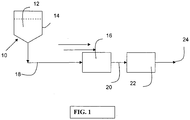
- FIG. 1 depicts one of the preferred embodiments of the process of this invention 10 utilizing a constant pressure mode of filtration.
- a protein solution 12 is retained by pressurized reservoir 14 and is pumped to the filtration media unit 16 by the pressure in the tank through conduit 18.
- the solution is subjected to a normal flow mode of filtration with the aggregates being retained by the media and the aggregate free solution discharged as the filtrate from the first step 10.
- the filtrate is passed through conduit 20 for further downstream processing such as the second step of filtration 22 (explained in detail below), and then to an outlet conduit 24.
- the second step of filtration 22 explained in detail below
- a pump to create the constant pressure of the system, although it is not preferred, as the pump output would need to be carefully controlled to a constant pressure via valves or pump speed and would require a feedback system to ensure that the pressure is kept constant.
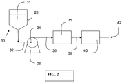
- FIG. 2 Another embodiment of this specification is shown in FIG. 2 in which a constant flow mode of operation is used.
- a pump 26 located between the reservoir 28 (typically non-pressurized, as compared to the pressurized reservoir 14 of the embodiment in FIG. 1 ) and the first filtration step 30 to maintain a constant flow.
- a protein solution 31 is pumped through conduit 32 to pump inlet 34, and then pumped through conduit 36 to the first filtration step 30.
- the protein solution 31 is subjected to a normal flow mode of filtration with the aggregates being retained by the filter of the first step 30, wherein the aggregate free solution is discharged as filtrate from the first step 30.
- the filtrate is passed through conduit 38 for further downstream processing such as the second step of filtration 40 (explained in detail below), and then to an outlet conduit 42.
- a valve (not shown) is the simplest means for controlling the flow between the recirculation loop and the downstream conduit.
- additional recirculation passes are generally unnecessary and increase manufacturing time and costs unnecessarily. It has been found that one recirculation pass is typically sufficient.
- Viruses are removed from the aggregate free solution by either a normal flow filter (NFF) or a tangential flow filtration (TFF) filter such as is described in U.S. Pat. No. 6,365,395, filed Nov. 3,2000 .
- NPF normal flow filter
- THF tangential flow filtration
- a protein solution is first prefiltered through a negatively charged coated microporous medium prefilter having a high charge density as taught herein, for the removal of protein aggregates.
- Prefiltration is preferably effected using a dead end NFF mode.
- Dead-end filtration refers to filtration where the entire fluid stream being filtered goes through the filter with no recycle or retentate flow. Whatever material does not pass through the filter either remains on the upper surface of the filter or remains within the filter.
- viral particle retention filters can be utilized downstream in a second step.
- the protein aggregate removal filter can be disposed of after use.
- filtration can be effected with one or more ultrafiltration membranes either by TFF or by dead end NFF, wherein the protein solution produced by this two step filtration process is agglomerate-free and viral-free protein.
- the one or more ultrafiltration membranes retain viral particles while permitting passage of protein monomers therethrough.
- the ultrafiltration membrane can be optionally flushed with water or an aqueous buffer solution to recover any protein retained by the membrane.
- a protein solution comprising protein trimers and higher protein polymers is first prefiltered with the negatively charged microporous coated membrane having a high charge density as taught herein, protein aggregates are selectively retained while permitting passage of protein monomers therethrough.
- This prefiltration step is effected using a prefilter having one or more layers of a negatively charged coated microporous membranes, wherein substantially complete protein aggregate removal from the protein solution is effected while permitting recovery of greater than about 85% protein monomers, preferably greater than about 90% protein monomers, and more preferably greater than 98%.
- the use of the negatively charged coated microporous membranes used in the prefiltration step to remove plugging constituents from a biomolecule solution provides substantial advantages over presently used conventional protein and viral particle separation processes. Since the filtration device of the first step (removing plugging constituents) is operated in the NFF mode, it may be disposable and there is no cleaning process that would be subject to validation procedures and the like. In addition, normal flow mode of operation is less expensive to purchase and operate, as less capital needs to be expended to set up such a system as compared to a TFF ultrafiltration type system. Furthermore, since the membrane utilized in the second filtration step of removing viral particles does not foul or plug with protein aggregates, its useful life is extended.
- Another advantage provided by the invention as taught herein includes the coated microporous membrane used in the first prefiltration step does not have to be an ultrafiltration membrane.
- the Vmax was at least 900% greater than that of the Vmax obtained without the NFF aggregate removal step.
- the present invention provides a simple means for the upstream removal of protein aggregates from a protein stream and/or solution before downstream viral filtration or other process steps occur. This prefiltation step reduces the fouling and clogging that would otherwise occur to downstream viral retention filters and the like, increasing throughput dramatically. Additionally, this is done without the need for TFF that is more costly to purchase and to run and which needs to be cleaned between uses.
- the present invention allows one to dispose of the aggregate filter allowing one to eliminate the cost of cleaning and storing the membrane between uses and the cost and time of validating one's procedures in doing so to regulatory agencies such as the FDA.
- the filtrate from the protein aggregate removal step is directed to a second filtration step.
- the second filtration step utilizes one or more viral retention filtration (typically ultrafiltration) membranes that can be conducted either in the TFF mode or the NFF mode.
- the filtration is conducted under conditions to retain the viral particles, generally having a 20 to 100 nanometer (nm) diameter, on the membrane surface while permitting passage of protein monomer and a portion of protein dimer through the membrane.
- Representative suitable ultrafiltration viral retention membranes used in the second step viral particle removal step include those formed from regenerated cellulose, polyethersulfones, polyarylsulphones, polysulfones, polyimides, polyamides, polyvinylidenedifluoride (PVDF) or the like, and include VIRESOLVE® NFP, VIRESOLVE® Pro, and RETROPORE® membranes available from Millipore Corporation of Billerica, MA, USA. These can be supplied in either a cartridge NFF form, such as VIRESOLVE® NFP viral filters, or as cassettes for TFF, such as PELLICON® cassettes, also available from Millipore Corporation of Billerica, MA, USA.
- Viral filters utilized in the process of this invention are characterized by a log retention value (LRV; the negative logarithm of the sieving coefficient) for viral particles and other, particles that increase monotonically with the diameter of the particle; in the size range of interest for viral particles of 20 to 100 nm diameter. Empirically, the LRV increases continuously with the size of the particle projected area (the square of the particle diameter).
- LRV log retention value
- the membranes utilized in the process of this invention are capable of producing an LRV for viral particles of 3 and can extend to as high as about 8 or greater where the viral particle size is between a 10 and 100 nm diameter.
- the protein stream free of protein aggregates can then be filtered through one or more ultrafiltration membranes to retain viral particles at a retention level of at least 3 LRV, and allow the passage therethrough of a protein solution free of viral particles and free protein aggregates.
- This specification further provides a device, e.g., a filter device, chromatography device, macromolecular transfer device, flow distributor arrangement, and/or a membrane module comprising one or more negatively charged microporous coated substrates as taught herein.
- the device can be in any suitable form, for example, the device can include a filter element comprising the negatively charged microporous coated substrate as taught herein in a substantially planar or pleated form.
- the filter element can have a hollow generally cylindrical form.
- the device can include the prefilter microporous coated membranes as taught herein in combination with upstream and/or downstream support or drainage layers.
- the device can include a plurality of membranes, e.g., to provide a multilayered filter element, or stacked to provide a membrane module, such as a membrane module for use in membrane chromatography.
- Filter cartridges can be constructed by including a housing and endcaps to provide fluid seal as well as at least one inlet and at least one outlet.
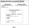
- the devices can be constructed to operate in crossflow or tangential flow (TFF) mode, as well as dead-end mode (NFF). Accordingly, the protein containing solution or stream to be treated can be passed, for example, tangentially to a membrane surface, or passed perpendicular to a membrane surface.
- the microporous coated membranes as taught herein may be used singularly or in groups, such that the protein containing solution contacts one or more prefilter elements either in parallel or series flow.
- the coated microporous membranes as taught herein can be used in groups, for example stacked multiple layers (generally from 3 to 8) sealed in the same housing. See, for example, U.S. Patent No. 2,788,901 to Boeddinghaus et al. and U.S. Patent No. 5,085,784 to Ostreicher .
- FIG. 1 depicts a first process step 10, wherein a constant pressure mode of filtration is utilized.
- a protein solution 12 is retained by pressurized reservoir 14 and is pumped to the filtration media unit 16 by the pressure in the tank through conduit 18.
- the protein solution 12 is subjected to a normal flow mode of filtration with the protein aggregates being retained by a negatively charged microporous coated media prefilter as taught herein, contained within the filtration media unit 16, and the protein aggregate free solution is discharged as filtrate from the first step 10.
- the filtrate is next passed through a conduit 20 for further downstream processing, such as a second filtration process step 22 (as explained infra), and wherein the filtrate exits process step 22 via an outlet conduit 24.
- a protein aggregate free solution results from protein aggregates being retained by media unit 16 having the negatively charged microporous coated media prefilter taught herein, while protein monomers and the like pass through the media unit 16.
- a pump can be used to create the constant pressure of the system although it is not preferred as the pump output would need to be carefully controlled to a constant pressure via valves or pump speed and would require a feedback system to ensure that the pressure is kept constant.
- FIG. 2 depicts a first process step 30, wherein a constant flow mode of operation is used.
- a pump 26 is located between the reservoir 28 (typically a non-pressurized reservoir, as compared to the pressurized reservoir vessel 14 of the embodiment shown FIG. 1 ), and the filtration media unit 35 to maintain a constant flow.
- the protein solution 31 is pumped through conduit 32 to the pump inlet 34, and pumped through conduit 36 to the filtration media unit 35.
- the prefilter used in the first step 30 is the negatively charged microporous coated media as taught herein, and also used in FIG. 1 .
- the protein solution 31 is subjected to a normal flow mode of filtration wherein protein aggregates are retained by the prefilter in the filtration media unit 35, and a protein aggregate free solution is discharged as filtrate and passed through conduit 38 for further downstream processing, such as a second filtration process step 40 (as explained infra), and then to an outlet conduit 42.
- a protein aggregate free solution results from protein aggregates being retained by media unit 35 having the negatively charged microporous coated media prefilter taught herein, while protein monomers and the like pass through the media unit 35.
- a recirculation loop (not shown) can be located at an outlet (not shown) of the first filtration step (10, 30) and recirculate the filtrate through the first filtration step one or more additional times to further reduce the protein aggregate level in the filtrate if needed.
- Use of a valve is the simplest means for controlling the flow between the recirculation loop and the downstream conduit. It has been found that one recirculation pass is sufficient. Additional recirculation passes are generally unnecessary and increase manufacturing time and costs unnecessarily.
- the membrane prefilter of the present invention operates predominantly by ionic binding of positively-charged protein aggregates on its negatively-charged surface. Based on this understanding of how the mechanism of the prefilter is thought to operate, operating conditions, choosing validation strategies, and addressing potential troubleshooting issues may appropriately be determined.
- the mechanism of the prefilter operation can be investigated by analyzing the prefilter's performance in a range of solution conditions. For example, conductivity and pH of a challenge solution were varied and the throughput of the prefilter/filter combination was measured. Heat-shocked SeraCare IgG (isoelectric point or "pl" of about 6-9) (SeraCare Life Sciences, Inc., Milford, MA, USA) was used in the challenge solution at 30 psig operating pressure. As depicted in FIG. 3 , the prefilter is most effective in a pH range below the pl of aggregates, and a conductivity range of about 2-16 mS/cm. The net positive charge on the aggregates is reduced as the pH approaches the pl, and overall charge interactions are weakened as the conductivity is increased. The relatively poor performance of the prefilter at high pH and high conductivity seems to confirm that ionic interactions are primarily responsible for aggregate removal from the antibody stream.
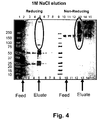
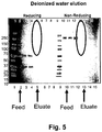
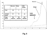
- the proteinaceous material bound to the membrane prefilter during the throughput testing was removed (eluted) and analyzed by sodium dodecyl sulfate polyacrylamide gel electrophoresis (SDS-PAGE) and size exclusion chromatography (SEC).
- SDS-PAGE sodium dodecyl sulfate polyacrylamide gel electrophoresis
- SEC size exclusion chromatography
- Two elution conditions were studied: elution with 1M NaCl solution (shown in FIG. 4 ) and with deionized water (shown in FIG. 5 ). From the SDS-PAGE data, no protein elution was observed in deionized water in FIG. 5 , while strong antibody and aggregate bands were present in 1M salt eluate FIG. 4 .
- the molecular weight of eluted protein was quantified with SEC as shown in FIG. 6 .
- HMW high molecular weight
- aqueous solution was prepared containing 4.5 wt.% of sodium salt of 2-acrylamido-2-methylpropanesulfonic acid (AMPS-Na) and 0.9% of N, N'-methylenebisacrylamide.
- AMPS-Na 2-acrylamido-2-methylpropanesulfonic acid
- N, N'-methylenebisacrylamide N, N'-methylenebisacrylamide.
- a hydrophilic polyethersulfone membrane with pore size rating 0.22 um commercially available as Millipore Express® SHF was cut into square pieces of 14 cm by 14 cm and submerged in this solution for 30 seconds to ensure complete wetting. The excess of solution was nipped off, and the membrane was exposed to 2 MRads of electron beam radiation under inert atmosphere. The membrane was subsequently rinsed with deionized water and dried in air.
- Example 1 The procedure outlined in Example 1 was followed but AMPS-Na was replaced with 4.0 wt.% of 2-acrylamido-2-methylpropanesulfonic acid (AMPS).
- AMPS 2-acrylamido-2-methylpropanesulfonic acid
- An aqueous solution was prepared containing 4.5 wt.% of sodium salt of 2-acrylamido-2-methylpropanesulfonic acid (AMPS-Na) and 0.9% of N, N'-methylenebisacrylamide.
- a hydrophobic polyethersulfone membrane with pore size rating 0.22 um unhydrophilized precursor of Millipore Express® SHF was cut into square pieces of 14 by 14 cm and submerged into isopropanol for 1 minute, transferred into deionized water for 5 minutes, and then submerged into the monomer solution for 3 minutes. The excess of solution was nipped off, and the membrane was exposed to 2 MRads of electron beam radiation under inert atmosphere. The membrane was subsequently rinsed with deionized water and dried in air. The testing procedure outlined in Example 1 was followed.
- Example 1 The procedure outlined in Example 1 was followed with a hydrophilic polyethersulfone membrane having pore size rating 0.8 um, commercially available under the trade name Micropes from Polypore Inc.'s unit Membrana GMBH, Wuppertal, Germany.
- aqueous solution was prepared containing 4.5 wt.% of sodium salt of 2-acrylamido-2-methylpropanesulfonic acid (AMPS-Na), 0.9% of N, N'-methylenebisacrylamide, and 0.2% of UV initiator 1-[4-(2-Hydroxyethoxy)-phenyl]-2-hydroxy-2-methyl-1-propane-1-one (available from Ciba Specialty Chemicals, Basel, Switzerland, under the trade name Irgacure® 2959).
- AMPS-Na 2-acrylamido-2-methylpropanesulfonic acid
- UV initiator 1-[4-(2-Hydroxyethoxy)-phenyl]-2-hydroxy-2-methyl-1-propane-1-one available from Ciba Specialty Chemicals, Basel, Switzerland, under the trade name Irgacure® 2959.
- a hydrophobic polyvinylidenedifluoride membrane with pore size rating 0.65 um was cut into square pieces of 14 cm by 14 cm and submerged into isopropanol for 1 minute, transferred into deionized water for 5 minutes, and then submerged into the monomer solution for 3 minutes. The excess of solution was nipped off, and the membrane was exposed to ultra-violet radiation under inert atmosphere. The membrane was subsequently rinsed with deionized water and dried in air. The testing procedure outlined in Example 1 was followed.
- An aqueous solution was prepared containing 4.5 wt.% of sodium salt of 2-acrylamido-2-methylpropanesulfonic acid (AMPS-Na), 0.9% of N, N'-methylenebisacrylamide, and 0.2% of UV initiator 1-[4-(2-Hydroxyethoxy)-phenyl]-2-hydroxy-2-methyl-1-propane-1-one (available from Ciba Specialty Chemicals, Basel, Switzerland, under the trade name Irgacure® 2959).
- a hydrophilic ultra-high molecular weight polyethylene membrane with pore size rating 0.65 um was cut into square pieces of 14 by 14 cm and submerged in this solution for 30 seconds to ensure complete wetting. The excess of solution was nipped off, and the membrane was exposed to ultra-violet radiation under inert atmosphere. The membrane was subsequently rinsed with deionized water and dried in air. The testing procedure outlined in Example 1 was followed.
- Modified membrane was prepared as described in Example 1. Molded polypropylene devices were manufactured containing 1, 2, 3, and 6 layers of this membrane, and tested as described in Example 1.
- Membrane prepared in Example 1 was exposed twice to gamma irradiation of 30 kGy each, for a total dosage of 60 kGy, i.e. 3 Mrads each, for a total dosage of 6 Mrads. Aggregate removal efficiency was tested before and after exposure as outlined in Example 1.
- Membrane prepared in Example 1 was flushed with 0.5N solution of sodium hydroxide for 1 hour at constant pressure 1.72 bar (25 psi), then flushed with deionized water for 60 min at 2.07 bar (30 psi), and tested for aggregate removal efficiency as outlined in Example 1.
- Example 1 Throughput testing was carried out as described in Example 1, with the exception that no prefiltration step was used. Two layers of Viresolve®Pro parvovirus removal membrane from Millipore Corporation were sealed in a polypropylene vented device. This device was first tested for permeability with acetate buffer solution, and then for throughput with an aggregate-containing solution of polyclonal antibodies prepared as described above. Table 1 shows the combined throughput of this filter combination.
- Example 5 A Viresolve® Prefilter from Millipore Corporation was used to remove protein aggregates from a protein stream.
- a commercially available device with 5 cm 2 filtration area was connected in-line to a Viresolve® Pro-containing device and tested as described above.
- Table 1 (example 5,6 are not according to the invention) Membrane Permeability, L/(m 2 h-psi) V 75 throughput of aggregate-containing solution of polyclonal antibodies, L/m 2 ⁇ permeability * 14.50 to obtain L/(m 2 hbar)
- Example 1 15.5 3549
- Example 3 14.1 2782
- Example 4 14.9 825
- Example 5 1.64 850
- Example 6 14.6 1602
- Example 7 1 Layer 15.5 708 2 Layers 14.6 1725 3 Layers 14.1 3549 6 Layers 13.7 11548
- Example 8 15.5 3879 Example 9 15.5 3743 Comparative Example 1 17 75 Comparative Example 2 12.8 14765
- Virus validation strategies and recommendations are developed by an understanding of virus binding to a prefilter.
- the Viresolve® Prefilter (cellulose fibers with Diatomite) has been shown to remove mammalian viruses by mixed-mode adsorption. Since it is a regulatory requirement to demonstrate virus removal by only size exclusion (SEC) during the validation of the virus filtration step, the Viresolve® Prefilter must be decoupled from the virus filter, as depicted in FIG. 7 .
- the feed material is first filtered through the Viresolve® Prefilter, and then spiked with virus, followed by virus filtration. In many cases, decoupling the Viresolve® Prefilter from the virus filter can lead to reduced capacities even in the absence of virus spikes.
- FIG. 7 schematically depicts a decoupled prefiltration mode of virus removal. While FIG. 8 schematically depicts a spike-across (coupled) prefiltration mode of virus removal.
- a potential benefit of a membrane based, negatively charged prefilter in accordance with this invention in a viral clearance application may be the ability to spike virus through the prefilter during virus validation to maximize capacities and improve ease of use.
- Feed samples collected from coupled devices resulted in minimal ( ⁇ 0.2logs) bacteriophage (Phi-X 174 and PP7) retention and approximately 0.6-1 logs of MMV across the prefilter. On average, about 2 logs of XMuLV were retained. This is most likely due to the size difference between this virus and the others in the test.
- An advantageous property of the negatively charged microporous coated media taught herein includes chemical resistance to withstand contact with highly alkaline solutions in cleaning or sanitation operations without loss of filtration properties, as well as other desirable surface, chemical and mechanical properties
- a prefiltration process using the negatively charged coated microporous media as taught herein and operated in the NFF mode to remove plugging and fouling constituents such as protein aggregates from a biological solution offers several advantages over currently used separation processes, because the coated microporous media is disposable, thereby requiring no cleaning process that would be subject to validation procedures. Additionally, the NFF mode of operation is less expensive to operate compared to a TFF ultrafiltration type systems.
- the negatively charged coated microporous media taught herein and used upstream from the removal of viral particles from a protein solution inhibits the fouling of the viral particle retention ultrafiltration media utilized downstream by retaining the fouling constituents upstream, thereby extending the useful life of the ultrafiltration viral particle retention media.
- the properties of the negatively charged coated microporous media of the present invention make them attractive for use in the prefiltration, detection, separation, and/or purification of biomolecules such as proteins, amino acids, nucleic acids, and viral particles.
- biomolecules such as proteins, amino acids, nucleic acids, and viral particles.
- nucleic acids include modified or unmodified, synthetic or natural RNA and DNA.
- the negatively charged coated microporous media as taught herein also finds use in various applications such as prefiltration and filtration of fluids containing proteins, positively charged atoms, molecules, biomolecules, and particulates, and macromolecular transfer from electrophoresis gels such as the transfer of nucleic acids and proteins from electrophoresis gels to an immobilizing matrix.
- coated microporous media as taught herein also find use in the separation or purification of various components present in biological fluids.
- the coated microporous media can be used in the purification of human albumin from serum, in the therapeutic fractionation of blood, and the separation of components in genetically engineered cell cultures or fermentation broths.
- the coated microporous media can also be used in the purification of, for example, viral vaccines and gene therapy vectors such as adeno-associated viral particles.
- the present invention provides a simple prefiltration means for the removal of protein aggregates from a protein stream upstream or before viral filtration or other downstream processing steps.
- the prefiltration means taught herein reduces the fouling and clogging that would otherwise occur to viral retention filters and the like, thereby increasing throughput and flux over traditional filtration processes that do not incorporate the coated microporous membrane as taught herein.
Claims (17)
- Negativ geladenes Filtermedium, umfassend
ein poröses Substrat, das mit einer negative geladenen polymerisierten vernetzten Acrylamidoalkylbeschichtung beschichtet ist, die in situ auf der Oberfläche des Substrats bei Exposition an einen Elektronenstrahl und in Abwesenheit eines radikalliefernden Polymerisierungsinitiators polymerisiert wird, wobei die Beschichtung nur Amid-Amid-Vernetzungen umfasst und aus einem polymerisierbaren Acrylamidoalkylmonomer, das 2- Acrylamido-2-methylpropansulfonsäure und Salze davon umfasst, und einem Acrylamido-Vernetzungsmittel, umfassend N,N'-Methylenbisacrylamid, gebildet ist, und ferner wobei die Beschichtung aus einer wässrigen Eduktlösung gebildet ist, die bezogen auf das Gewicht der Eduktlösung 1 - 20 Gew. % 2-Acrylamido-2-methylpropansulfonsäure und Salze davon und bezogen auf das Gewicht der 2-Acrylamido-2-methylpropansulfonsäure und der Salze davon 5 - 100 Gew. % N, N'-Methylenbisacrylamid umfasst, dadurch gekennzeichnet, dass die Beschichtung durch Exposition der Beschichtung an einen Elektronenstrahl, der eine Strahlungsdosis von 0,1 - 6 Mrad über mindestens 0,1 s bereitstellt, polymerisiert wird. - Medium nach Anspruch 1, wobei das poröse Substrat ein Material umfasst, das aus der nachfolgenden Gruppe gewählt ist: substituierte oder nicht substituierte Polyacrylamide, Polystyrole, Polymethacrylamide, Polyimide, Polyacrylate, Polycarbonate, Polymethacrylate, Polyvinylpolymere, Polysulfone, Polyethersulfone, Copolymere von Styrol und Divinylbenzol, aromatische Polysulfone, Polytetrafluorethylen (PTFE), perfluorierte thermoplastische Polymere, Polyolefine, aromatische Polyamide, aliphatische Polyamide, ultrahochmolekulare Polyethylene, Polyvinylidendifluorid (PVDF), Polyetheretherketone (PEEK), Polysaccharide, Polyester, Cellulose, Cellulosederivate, Glasfaser, Baumwolle, Keramik, Metalle, Vliesstoffe und Kombinationen davon.
- Medium nach Anspruch 1, wobei das poröse Substrat mit einer benetzenden Flüssigkeit gewaschen wird, um das Substrat zu benetzen, bevor dieses mit der negativ geladenen polymerisierten vernetzten Acryloamidoalkylbeschichtung beschichtet wird.
- Medium nach Anspruch 1, wobei das poröse Substrat umfasst:a) eine mikroporöse Membran oderb) mindestens eine plissierte mikroporöse Membran.
- Medium nach Anspruch 1, das eine hohlzylindrische Form aufweist.
- Negative geladene beschichtete poröse Membran, umfassend das Medium nach einem der Ansprüche 1 - 5, wobei das Substrat umfasst:eine poröse Membran mit Innen- und Außenflächen, und wobei die negative geladene polymerisierte vernetzte Acryloamidoalkylbeschichtung, die nur Amid-Amid-Vernetzungen aufweist, in situ auf den Innen- und Außenflächen der porösen Membran polymerisiert wird.
- Verfahren zur Herstellung eines negative geladenen polymerisierten, vernetzten, beschichteten, porösen Medium, umfassend die Schritte:a) Vorsehen eines porösen Substrats mit Innen- und Außenflächen;b) Vorsehen einer wässrigen Eduktlösung aus polymerisierbaren Acrylamidoalkylmonomeren, die 2-Acrylamido-2-methylpropansulfonsäure und Salze davon umfasst, wobei das Acrylamido-Vernetzungsmittel N, N'-Methylenbisacrylamid umfasst;c) Kontaktieren des porösen Substrats mit der Eduktlösung;d) Bilden einer negativ geladenen, vernetzten Beschichtungszusammensetzung, die nur Amid-Amid-Vernetzungen aufweist, aus der Eduktlösung auf dem porösen Substrat, wobei die Eduktlösung, bezogen auf das Gewicht der Eduktlösung, 1 - 20 Gew. % 2-Acrylamido-2-methylpropansulfonsäure und Salze davon und, bezogen auf das Gewicht der 2-Acrylamido-2-methylpropansulfonsäure und der Salze davon, 5 - 100 Gew. % N,N'-Methylenbisacrylamid umfasst;e) Polymerisieren der negative geladenen, vernetzten Beschichtungszusammensetzung in situ auf dem porösen Substrat in Abwesenheit eines radikalliefernden chemischen Polymerisierungsinitiators, dadurch gekennzeichnet, dass die Beschichtung durch Exposition der Beschichtung an einen Elektronenstrahl polymerisiert wird, der eine Strahlungsdosis von 0,1 - 6 Mrad über mindestens etwa 0,1 s bereitstellt; undf) Bilden einer polymerisierten, negativ geladenen, vernetzten Beschichtung auf dem porösen Substrat.
- Verfahren nach Anspruch 7, ferner umfassend einen Schritt (a1) zwischen den Schritten (a) und (b): Waschen des porösen Substrats mit einer benetzenden Flüssigkeit, um dieses zu benetzen.
- Verfahren nach Anspruch 8, ferner umfassend einen zusätzlichen Waschschritt zwischen den Schritten (a1) und (b): Waschen des nassen porösen Substrats mit einer zweiten benetzenden Flüssigkeit, um die erste benetzende Flüssigkeit zu ersetzen, wobei das poröse Substrat mit der zweiten Flüssigkeit benetzt wird.
- Verfahren nach einem der Ansprüche 7 - 9, wobei der Schritt (c) umfasst: Eintauchen des porösen Substrats in ein Eduktlösungsbad, Sättigen der Innen- und Außenflächen des Substrats, Entnehmen des beschichteten Substrats aus dem Eduktlösungsbad und ggf. Entfernen der überschüssigen Eduktlösung vom beschichteten Substrat.
- Verfahren nach einem der Ansprüche 7 - 10, wobei das poröse Substrat ein Material umfasst, das aus der nachfolgenden Gruppe gewählt ist: substituierte oder nicht substituierte Polyacrylamide, Polystyrole, Polymethacrylamide, Polyimide, Polyacrylate, Polycarbonate, Polymethacrylate, Polyvinylpolymere, Polysulfone, Polyethersulfone, Copolymere von Styrol und Divinylbenzol, aromatische Polysulfone, Polytetrafluorethylen (PTFE), perfluorierte thermoplastische Polymere, Polyolefine, aromatische Polyamide, aliphatische Polyamide, ultrahochmolekulare Polyethylene, Polyvinylidendifluorid (PVDF), Polyetheretherketone (PEEK), Polysaccharide, Polyester, Cellulose, Cellulosederivate, Glasfaser, Baumwolle, Keramik, Metalle, Vliesstoffe und Kombinationen davon.
- Verfahren nach einem der Ansprüche 7 - 11, wobei das poröse Substrat eine mikroporöse Membran umfasst.
- Vorrichtung zur Flüssigkeitsaufbereitung, umfassend:ein Gehäuse, das mindestens eine Eintrittsöffnung, mindestens eine Austrittsöffnung umfasst und einen Strömungsweg zwischen Eintritts- und Austrittsöffnung definiert, wobei zwischen Eintritts- und Austrittsöffnung und quer über den Strömungsweg eine Mehrzahl negativ geladener mikroporöser Membranen nach Anspruch 4 oder 6 angeordnet ist.
- Verfahren zur selektiven Entfernung von Proteinaggregaten und Viruspartikeln au seiner Proteinlösung, die Proteinaggregate und Viruspartikel enthält, umfassend die Schritte:a) Filtern einer Proteinlösung, die Proteinaggregate und Viruspartikel enthält, durch ein negativ geladenes, mikroporöses Medium nach einem der Ansprüche 1 - 5;b) Zurückgewinnen einer Proteinlösung, die im Wesentlichen frei von Proteinaggregaten ist;c) Filtern der zurückgewonnenen Proteinlösung durch mindestens eine Ultrafiltrationsmembran;d) Zurückbehalten von Viruspartikeln in der mindestens einen Ultrafiltrationsmembran auf einem Niveau von mindestens 3 LRV (Log-Rückhaltewert) unde) Zurückgewinnen einer Proteinlösung, die im Wesentlichen frei von Viruspartikeln ist.
- Verfahren nach Anspruch 14, ferner umfassend den Schritt: Spülen des auf der mindestens einen Ultrafiltrationsmembran zurückbehaltenen Proteins.
- Verfahren nach Anspruch 15, wobei der Schritt (a) Filtern einen Filtermodus mit normalem Durchfluss umfasst.
- Verfahren nach Anspruch 14, wobei der Schritt (c) Filtern einen Filtermodus entweder mit normaler Strömung oder mit Tangentialströmung umfasst.
Applications Claiming Priority (2)
| Application Number | Priority Date | Filing Date | Title |
|---|---|---|---|
| US20878409P | 2009-02-27 | 2009-02-27 | |
| PCT/US2010/000578 WO2010098867A1 (en) | 2009-02-27 | 2010-02-26 | Membrane with sulfonic groups for removing protein aggregates |
Publications (2)
| Publication Number | Publication Date |
|---|---|
| EP2401065A1 EP2401065A1 (de) | 2012-01-04 |
| EP2401065B1 true EP2401065B1 (de) | 2017-12-13 |
Family
ID=42224444
Family Applications (1)
| Application Number | Title | Priority Date | Filing Date |
|---|---|---|---|
| EP10707995.6A Active EP2401065B1 (de) | 2009-02-27 | 2010-02-26 | Membran mit sulfonsäuregruppen zum entfernen von proteinaggregaten |
Country Status (7)
| Country | Link |
|---|---|
| US (2) | US20130056415A1 (de) |
| EP (1) | EP2401065B1 (de) |
| JP (2) | JP6141597B2 (de) |
| CN (2) | CN102333583B (de) |
| ES (1) | ES2661237T3 (de) |
| SG (2) | SG173491A1 (de) |
| WO (1) | WO2010098867A1 (de) |
Families Citing this family (25)
| Publication number | Priority date | Publication date | Assignee | Title |
|---|---|---|---|---|
| DE102011105525B4 (de) * | 2011-06-24 | 2015-03-26 | Sartorius Stedim Biotech Gmbh | Verfahren zur Abtrennung von Biopolymer-Aggregaten und Viren aus einem Fluid |
| ES2705000T3 (es) * | 2011-07-25 | 2019-03-21 | Fujifilm Mfg Europe Bv | Método para producir membranas compuestas con poros llenos de polímero |
| CN102443109B (zh) * | 2011-09-23 | 2013-07-31 | 长春工业大学 | 一种官能化超高分子量聚乙烯树脂及其制备方法 |
| SG10201701224UA (en) * | 2012-03-12 | 2017-04-27 | Merck Patent Gmbh | Removal of protein aggregates from biopharmaceutical preparations in a flowthrough mode |
| US20130284669A1 (en) * | 2012-04-25 | 2013-10-31 | Millipore Corporation | Negatively charged porous medium for removing protein aggregates |
| EP2682168A1 (de) | 2012-07-02 | 2014-01-08 | Millipore Corporation | Reinigung biologischer Moleküle |
| CA2885263C (en) | 2012-09-17 | 2021-11-16 | W. R. Grace & Co.-Conn. | Chromatography media and devices |
| CN103272502B (zh) * | 2013-06-24 | 2015-07-08 | 南京大学 | 一种荷负电微滤复合膜的制造方法及应用 |
| EP3019262A1 (de) | 2013-07-12 | 2016-05-18 | Merck Patent GmbH | Entfernung von fragmenten von einer probe mit einem zielprotein unter verwendung von aktivkohlenstoff |
| CN110054661A (zh) * | 2013-12-12 | 2019-07-26 | Emd密理博公司 | 使用含丙烯酰胺的过滤器分离蛋白 |
| JP6853670B2 (ja) | 2014-01-16 | 2021-04-07 | ダブリュー・アール・グレース・アンド・カンパニー−コーンW R Grace & Co−Conn | 親和性クロマトグラフィー媒体及びクロマトグラフィーデバイス |
| WO2015168383A1 (en) | 2014-05-02 | 2015-11-05 | W. R. Grace & Co.-Conn. | Functionalized support material and methods of making and using functionalized support material |
| JP6437553B2 (ja) | 2014-07-25 | 2018-12-12 | 旭化成メディカル株式会社 | 陽イオン交換クロマトグラフィー担体及びその使用方法 |
| ES2786179T3 (es) * | 2014-11-04 | 2020-10-09 | Asahi Kasei Medical Co Ltd | Membrana de filtración de fibras huecas |
| SG10201911134QA (en) | 2015-06-05 | 2020-01-30 | Grace W R & Co | Adsorbent bioprocessing clarification agents and methods of making and using the same |
| DE102016005049B4 (de) * | 2016-04-26 | 2020-06-18 | Sartorius Stedim Biotech Gmbh | Verfahren zur Bestimmung des logarithmischen Reduktionswertes LRV eines Größenausschlussfilters |
| JP7138096B2 (ja) * | 2016-09-09 | 2022-09-15 | スリーエム イノベイティブ プロパティズ カンパニー | 生物学的溶液中の単量体タンパク質から凝集タンパク質を分離するための方法 |
| JP7085533B2 (ja) | 2016-09-09 | 2022-06-16 | スリーエム イノベイティブ プロパティズ カンパニー | 官能化コポリマー及びその使用 |
| WO2018230397A1 (ja) * | 2017-06-12 | 2018-12-20 | 旭化成メディカル株式会社 | タンパク質含有液のろ過方法 |
| EP3773969A1 (de) * | 2018-04-03 | 2021-02-17 | Merck Patent GmbH | Cex-chromatografiemedien und salzarme elution von zielproteinen aus biopharmazeutischen speisungen |
| KR102009256B1 (ko) * | 2018-06-05 | 2019-08-09 | 한국에너지기술연구원 | 광경화성 용액의 제조방법 및 이를 포함하는 양이온교환막의 제조방법 |
| US11045773B2 (en) * | 2018-08-31 | 2021-06-29 | Pall Corporation | Salt tolerant porous medium |
| JP7273142B2 (ja) * | 2019-03-29 | 2023-05-12 | 旭化成メディカル株式会社 | タンパク質の精製方法 |
| EP3954725B1 (de) * | 2019-04-08 | 2024-03-06 | Asahi Kasei Medical Co., Ltd. | Polyamidmedium zur reinigung einer protein enthaltenden lösung und verfahren zur herstellung eines polyamidmediums |
| WO2024008256A1 (en) * | 2022-07-05 | 2024-01-11 | Lihme Protein Solutions | Improved apparatus for compound separation |
Citations (1)
| Publication number | Priority date | Publication date | Assignee | Title |
|---|---|---|---|---|
| JP2005082728A (ja) * | 2003-09-09 | 2005-03-31 | Toagosei Co Ltd | 機能性膜の連続製造方法 |
Family Cites Families (26)
| Publication number | Priority date | Publication date | Assignee | Title |
|---|---|---|---|---|
| US2788901A (en) | 1954-10-11 | 1957-04-16 | American Felt Co | Fused edge filter unit |
| JPS5430284A (en) * | 1977-08-12 | 1979-03-06 | Terumo Corp | Method of making film |
| US4618533A (en) | 1984-11-30 | 1986-10-21 | Millipore Corporation | Porous membrane having hydrophilic surface and process |
| US5085784A (en) | 1989-04-07 | 1992-02-04 | Cuno, Incorporated | Use of cationic charge modified filter media |
| US4944879A (en) | 1989-07-27 | 1990-07-31 | Millipore Corporation | Membrane having hydrophilic surface |
| EP0772488B1 (de) | 1994-07-28 | 2001-01-31 | Millipore Corporation | Porösesverbundmembran und verfahren |
| US6039872A (en) * | 1997-10-27 | 2000-03-21 | Pall Corporation | Hydrophilic membrane |
| AU3376400A (en) * | 1999-02-25 | 2000-09-14 | Pall Corporation | Negatively charged membrane |
| US6783937B1 (en) * | 1999-02-25 | 2004-08-31 | Pall Corporation | Negatively charged membrane |
| US6849185B1 (en) * | 1999-05-14 | 2005-02-01 | Pall Corp | Charged membrane |
| CA2371060A1 (en) * | 1999-05-14 | 2000-11-23 | Pall Corporation | Charged membrane |
| EP1246682B1 (de) * | 2000-01-14 | 2007-11-28 | Entegris, Inc. | Filtriermethode basierend auf einem neutralen verhalten des filtermaterials |
| US6365395B1 (en) | 2000-11-03 | 2002-04-02 | Millipore Corporation | Process for removing protein aggregates and virus from a protein solution |
| US7118675B2 (en) * | 2002-02-04 | 2006-10-10 | Millipore Corporation | Process for removing protein aggregates and virus from a protein solution |
| AU2003211739A1 (en) * | 2002-03-07 | 2003-10-08 | Ube Industries. Ltd. | Electrolyte film and solid polymer fuel cell using the same |
| US7073671B2 (en) * | 2002-06-07 | 2006-07-11 | Millipore Corporation | Microporous membrane substrate having caustic stable, low protein binding surface |
| WO2004073843A1 (en) * | 2003-02-19 | 2004-09-02 | Mcmaster University | Composite materials comprising supported porous gels |
| ATE366617T1 (de) * | 2003-05-19 | 2007-08-15 | Millipore Corp | Verfahren zur vorfilterung einer proteinlösung |
| JP4427291B2 (ja) * | 2003-09-03 | 2010-03-03 | 東亞合成株式会社 | 機能性膜の連続製造方法 |
| US7179847B2 (en) * | 2003-11-13 | 2007-02-20 | 3M Innovative Properties Company | Polymer electrolytes crosslinked by e-beam |
| US8025696B2 (en) * | 2004-06-18 | 2011-09-27 | National University Corporation Hokkaido University | Artificial meniscus and process of making thereof |
| JP4748655B2 (ja) * | 2004-06-25 | 2011-08-17 | ミリポア・コーポレイション | 限外濾過膜および製造方法 |
| KR20080003789A (ko) * | 2005-03-09 | 2008-01-08 | 더 리전츠 오브 더 유니버시티 오브 캘리포니아 | 나노복합체막 및 이의 제조 및 사용 방법 |
| TW200733460A (en) * | 2006-02-15 | 2007-09-01 | Toagosei Co Ltd | Method for preparing functional film |
| JP4721439B2 (ja) * | 2006-05-17 | 2011-07-13 | 株式会社 資生堂 | ジェル状化粧料 |
| CN101557839B (zh) * | 2006-11-29 | 2013-05-15 | 国立大学法人北海道大学 | 软骨组织再生治疗用骨填充剂 |
-
2010
- 2010-02-26 WO PCT/US2010/000578 patent/WO2010098867A1/en active Application Filing
- 2010-02-26 US US13/504,085 patent/US20130056415A1/en not_active Abandoned
- 2010-02-26 CN CN201080009642.8A patent/CN102333583B/zh active Active
- 2010-02-26 SG SG2011055373A patent/SG173491A1/en unknown
- 2010-02-26 CN CN201510154638.5A patent/CN104801204B/zh active Active
- 2010-02-26 EP EP10707995.6A patent/EP2401065B1/de active Active
- 2010-02-26 SG SG10201609893SA patent/SG10201609893SA/en unknown
- 2010-02-26 ES ES10707995.6T patent/ES2661237T3/es active Active
- 2010-02-26 JP JP2011552030A patent/JP6141597B2/ja active Active
-
2015
- 2015-09-25 JP JP2015187740A patent/JP2016041424A/ja active Pending
- 2015-10-08 US US14/878,030 patent/US20160051943A1/en not_active Abandoned
Patent Citations (1)
| Publication number | Priority date | Publication date | Assignee | Title |
|---|---|---|---|---|
| JP2005082728A (ja) * | 2003-09-09 | 2005-03-31 | Toagosei Co Ltd | 機能性膜の連続製造方法 |
Also Published As
| Publication number | Publication date |
|---|---|
| JP6141597B2 (ja) | 2017-06-07 |
| EP2401065A1 (de) | 2012-01-04 |
| ES2661237T3 (es) | 2018-03-28 |
| CN104801204A (zh) | 2015-07-29 |
| CN102333583B (zh) | 2015-09-30 |
| WO2010098867A1 (en) | 2010-09-02 |
| US20160051943A1 (en) | 2016-02-25 |
| JP2012519065A (ja) | 2012-08-23 |
| WO2010098867A8 (en) | 2011-04-28 |
| CN102333583A (zh) | 2012-01-25 |
| US20130056415A1 (en) | 2013-03-07 |
| SG173491A1 (en) | 2011-09-29 |
| JP2016041424A (ja) | 2016-03-31 |
| CN104801204B (zh) | 2019-01-01 |
| SG10201609893SA (en) | 2017-01-27 |
Similar Documents
| Publication | Publication Date | Title |
|---|---|---|
| EP2401065B1 (de) | Membran mit sulfonsäuregruppen zum entfernen von proteinaggregaten | |
| EP1775016B1 (de) | Mit Hydroxyalkylcellulose hydrophilisierte Ultrafiltrationsmembran sowie Herstellungsmethode und Anwendung hierfür | |
| RU2698822C1 (ru) | Упорядоченный фильтрующий материал для очистки биоматериала | |
| EP1511558B1 (de) | Mikroporöses membran-substrat mit basenstabiler, wenig protein bindender oberfläche | |
| EP1381447B1 (de) | Beschichtete membranen | |
| JP5014576B2 (ja) | 多孔質複合膜及びその製造法 | |
| TWI412394B (zh) | Purification of proteins | |
| US20130284669A1 (en) | Negatively charged porous medium for removing protein aggregates | |
| WO2007102427A1 (ja) | 孔拡散式平膜分離装置・平膜濃縮装置・孔拡散用再生セルロース多孔膜および非破壊式の平膜検査方法 | |
| WO2008091658A1 (en) | Modified porous membranes, methods of membrane pore modification, and methods of use thereof | |
| JP2012245002A (ja) | 合成生体分子の精製及び濃縮 | |
| JP5756328B2 (ja) | グラフト鎖を導入する方法、多孔質吸着膜、及びタンパク質の精製方法 | |
| CN116528968A (zh) | 多孔中空纤维膜及完整性试验方法 | |
| CA2578202C (en) | Fractionation apparatus | |
| CN114653222A (zh) | 一种低非特异性吸附的除病毒滤膜及其制备方法 | |
| Brose et al. | Membrane filtration | |
| JP2023184194A (ja) | クロマトグラフィー担体を使用するタンパク質の精製方法 | |
| EP1779922A1 (de) | Neue beschichtete Membranen und andere Artikel | |
| JPH0323177B2 (de) | ||
| JP2010024412A (ja) | イオン交換膜、タンパク質精製モジュール、及びタンパク質の分離方法 |
Legal Events
| Date | Code | Title | Description |
|---|---|---|---|
| PUAI | Public reference made under article 153(3) epc to a published international application that has entered the european phase |
Free format text: ORIGINAL CODE: 0009012 |
|
| 17P | Request for examination filed |
Effective date: 20110808 |
|
| AK | Designated contracting states |
Kind code of ref document: A1 Designated state(s): AT BE BG CH CY CZ DE DK EE ES FI FR GB GR HR HU IE IS IT LI LT LU LV MC MK MT NL NO PL PT RO SE SI SK SM TR |
|
| RAP1 | Party data changed (applicant data changed or rights of an application transferred) |
Owner name: EMD MILLIPORE CORPORATION |
|
| DAX | Request for extension of the european patent (deleted) | ||
| 17Q | First examination report despatched |
Effective date: 20141105 |
|
| GRAP | Despatch of communication of intention to grant a patent |
Free format text: ORIGINAL CODE: EPIDOSNIGR1 |
|
| INTG | Intention to grant announced |
Effective date: 20170705 |
|
| GRAS | Grant fee paid |
Free format text: ORIGINAL CODE: EPIDOSNIGR3 |
|
| GRAA | (expected) grant |
Free format text: ORIGINAL CODE: 0009210 |
|
| AK | Designated contracting states |
Kind code of ref document: B1 Designated state(s): AT BE BG CH CY CZ DE DK EE ES FI FR GB GR HR HU IE IS IT LI LT LU LV MC MK MT NL NO PL PT RO SE SI SK SM TR |
|
| REG | Reference to a national code |
Ref country code: GB Ref legal event code: FG4D |
|
| REG | Reference to a national code |
Ref country code: AT Ref legal event code: REF Ref document number: 953846 Country of ref document: AT Kind code of ref document: T Effective date: 20171215 Ref country code: CH Ref legal event code: EP |
|
| REG | Reference to a national code |
Ref country code: IE Ref legal event code: FG4D |
|
| REG | Reference to a national code |
Ref country code: DE Ref legal event code: R096 Ref document number: 602010047317 Country of ref document: DE Ref country code: FR Ref legal event code: PLFP Year of fee payment: 9 |
|
| REG | Reference to a national code |
Ref country code: CH Ref legal event code: NV Representative=s name: FELBER UND PARTNER AG, CH |
|
| RAP2 | Party data changed (patent owner data changed or rights of a patent transferred) |
Owner name: EMD MILLIPORE CORPORATION |
|
| REG | Reference to a national code |
Ref country code: NL Ref legal event code: FP |
|
| REG | Reference to a national code |
Ref country code: ES Ref legal event code: FG2A Ref document number: 2661237 Country of ref document: ES Kind code of ref document: T3 Effective date: 20180328 |
|
| REG | Reference to a national code |
Ref country code: LT Ref legal event code: MG4D |
|
| PG25 | Lapsed in a contracting state [announced via postgrant information from national office to epo] |
Ref country code: SE Free format text: LAPSE BECAUSE OF FAILURE TO SUBMIT A TRANSLATION OF THE DESCRIPTION OR TO PAY THE FEE WITHIN THE PRESCRIBED TIME-LIMIT Effective date: 20171213 Ref country code: FI Free format text: LAPSE BECAUSE OF FAILURE TO SUBMIT A TRANSLATION OF THE DESCRIPTION OR TO PAY THE FEE WITHIN THE PRESCRIBED TIME-LIMIT Effective date: 20171213 Ref country code: LT Free format text: LAPSE BECAUSE OF FAILURE TO SUBMIT A TRANSLATION OF THE DESCRIPTION OR TO PAY THE FEE WITHIN THE PRESCRIBED TIME-LIMIT Effective date: 20171213 Ref country code: NO Free format text: LAPSE BECAUSE OF FAILURE TO SUBMIT A TRANSLATION OF THE DESCRIPTION OR TO PAY THE FEE WITHIN THE PRESCRIBED TIME-LIMIT Effective date: 20180313 |
|
| REG | Reference to a national code |
Ref country code: AT Ref legal event code: MK05 Ref document number: 953846 Country of ref document: AT Kind code of ref document: T Effective date: 20171213 |
|
| PG25 | Lapsed in a contracting state [announced via postgrant information from national office to epo] |
Ref country code: GR Free format text: LAPSE BECAUSE OF FAILURE TO SUBMIT A TRANSLATION OF THE DESCRIPTION OR TO PAY THE FEE WITHIN THE PRESCRIBED TIME-LIMIT Effective date: 20180314 Ref country code: HR Free format text: LAPSE BECAUSE OF FAILURE TO SUBMIT A TRANSLATION OF THE DESCRIPTION OR TO PAY THE FEE WITHIN THE PRESCRIBED TIME-LIMIT Effective date: 20171213 Ref country code: LV Free format text: LAPSE BECAUSE OF FAILURE TO SUBMIT A TRANSLATION OF THE DESCRIPTION OR TO PAY THE FEE WITHIN THE PRESCRIBED TIME-LIMIT Effective date: 20171213 Ref country code: BG Free format text: LAPSE BECAUSE OF FAILURE TO SUBMIT A TRANSLATION OF THE DESCRIPTION OR TO PAY THE FEE WITHIN THE PRESCRIBED TIME-LIMIT Effective date: 20180313 |
|
| PG25 | Lapsed in a contracting state [announced via postgrant information from national office to epo] |
Ref country code: CZ Free format text: LAPSE BECAUSE OF FAILURE TO SUBMIT A TRANSLATION OF THE DESCRIPTION OR TO PAY THE FEE WITHIN THE PRESCRIBED TIME-LIMIT Effective date: 20171213 Ref country code: CY Free format text: LAPSE BECAUSE OF FAILURE TO SUBMIT A TRANSLATION OF THE DESCRIPTION OR TO PAY THE FEE WITHIN THE PRESCRIBED TIME-LIMIT Effective date: 20171213 Ref country code: EE Free format text: LAPSE BECAUSE OF FAILURE TO SUBMIT A TRANSLATION OF THE DESCRIPTION OR TO PAY THE FEE WITHIN THE PRESCRIBED TIME-LIMIT Effective date: 20171213 Ref country code: SK Free format text: LAPSE BECAUSE OF FAILURE TO SUBMIT A TRANSLATION OF THE DESCRIPTION OR TO PAY THE FEE WITHIN THE PRESCRIBED TIME-LIMIT Effective date: 20171213 |
|
| PG25 | Lapsed in a contracting state [announced via postgrant information from national office to epo] |
Ref country code: SM Free format text: LAPSE BECAUSE OF FAILURE TO SUBMIT A TRANSLATION OF THE DESCRIPTION OR TO PAY THE FEE WITHIN THE PRESCRIBED TIME-LIMIT Effective date: 20171213 Ref country code: IS Free format text: LAPSE BECAUSE OF FAILURE TO SUBMIT A TRANSLATION OF THE DESCRIPTION OR TO PAY THE FEE WITHIN THE PRESCRIBED TIME-LIMIT Effective date: 20180413 Ref country code: RO Free format text: LAPSE BECAUSE OF FAILURE TO SUBMIT A TRANSLATION OF THE DESCRIPTION OR TO PAY THE FEE WITHIN THE PRESCRIBED TIME-LIMIT Effective date: 20171213 Ref country code: AT Free format text: LAPSE BECAUSE OF FAILURE TO SUBMIT A TRANSLATION OF THE DESCRIPTION OR TO PAY THE FEE WITHIN THE PRESCRIBED TIME-LIMIT Effective date: 20171213 Ref country code: PL Free format text: LAPSE BECAUSE OF FAILURE TO SUBMIT A TRANSLATION OF THE DESCRIPTION OR TO PAY THE FEE WITHIN THE PRESCRIBED TIME-LIMIT Effective date: 20171213 |
|
| REG | Reference to a national code |
Ref country code: DE Ref legal event code: R097 Ref document number: 602010047317 Country of ref document: DE |
|
| PG25 | Lapsed in a contracting state [announced via postgrant information from national office to epo] |
Ref country code: MC Free format text: LAPSE BECAUSE OF FAILURE TO SUBMIT A TRANSLATION OF THE DESCRIPTION OR TO PAY THE FEE WITHIN THE PRESCRIBED TIME-LIMIT Effective date: 20171213 |
|
| PLBE | No opposition filed within time limit |
Free format text: ORIGINAL CODE: 0009261 |
|
| STAA | Information on the status of an ep patent application or granted ep patent |
Free format text: STATUS: NO OPPOSITION FILED WITHIN TIME LIMIT |
|
| 26N | No opposition filed |
Effective date: 20180914 |
|
| PG25 | Lapsed in a contracting state [announced via postgrant information from national office to epo] |
Ref country code: DK Free format text: LAPSE BECAUSE OF FAILURE TO SUBMIT A TRANSLATION OF THE DESCRIPTION OR TO PAY THE FEE WITHIN THE PRESCRIBED TIME-LIMIT Effective date: 20171213 Ref country code: LU Free format text: LAPSE BECAUSE OF NON-PAYMENT OF DUE FEES Effective date: 20180226 |
|
| PG25 | Lapsed in a contracting state [announced via postgrant information from national office to epo] |
Ref country code: SI Free format text: LAPSE BECAUSE OF FAILURE TO SUBMIT A TRANSLATION OF THE DESCRIPTION OR TO PAY THE FEE WITHIN THE PRESCRIBED TIME-LIMIT Effective date: 20171213 |
|
| PG25 | Lapsed in a contracting state [announced via postgrant information from national office to epo] |
Ref country code: MT Free format text: LAPSE BECAUSE OF NON-PAYMENT OF DUE FEES Effective date: 20180226 |
|
| PG25 | Lapsed in a contracting state [announced via postgrant information from national office to epo] |
Ref country code: TR Free format text: LAPSE BECAUSE OF FAILURE TO SUBMIT A TRANSLATION OF THE DESCRIPTION OR TO PAY THE FEE WITHIN THE PRESCRIBED TIME-LIMIT Effective date: 20171213 |
|
| PG25 | Lapsed in a contracting state [announced via postgrant information from national office to epo] |
Ref country code: PT Free format text: LAPSE BECAUSE OF FAILURE TO SUBMIT A TRANSLATION OF THE DESCRIPTION OR TO PAY THE FEE WITHIN THE PRESCRIBED TIME-LIMIT Effective date: 20171213 Ref country code: HU Free format text: LAPSE BECAUSE OF FAILURE TO SUBMIT A TRANSLATION OF THE DESCRIPTION OR TO PAY THE FEE WITHIN THE PRESCRIBED TIME-LIMIT; INVALID AB INITIO Effective date: 20100226 |
|
| PG25 | Lapsed in a contracting state [announced via postgrant information from national office to epo] |
Ref country code: MK Free format text: LAPSE BECAUSE OF NON-PAYMENT OF DUE FEES Effective date: 20171213 |
|
| PGFP | Annual fee paid to national office [announced via postgrant information from national office to epo] |
Ref country code: IE Payment date: 20230110 Year of fee payment: 14 Ref country code: FR Payment date: 20230110 Year of fee payment: 14 Ref country code: ES Payment date: 20230310 Year of fee payment: 14 Ref country code: CH Payment date: 20230307 Year of fee payment: 14 |
|
| PGFP | Annual fee paid to national office [announced via postgrant information from national office to epo] |
Ref country code: IT Payment date: 20230110 Year of fee payment: 14 Ref country code: GB Payment date: 20230105 Year of fee payment: 14 Ref country code: DE Payment date: 20221230 Year of fee payment: 14 Ref country code: BE Payment date: 20230117 Year of fee payment: 14 |
|
| PGFP | Annual fee paid to national office [announced via postgrant information from national office to epo] |
Ref country code: NL Payment date: 20230113 Year of fee payment: 14 |
|
| P01 | Opt-out of the competence of the unified patent court (upc) registered |
Effective date: 20230602 |
|
| PGFP | Annual fee paid to national office [announced via postgrant information from national office to epo] |
Ref country code: NL Payment date: 20240108 Year of fee payment: 15 |
|
| PGFP | Annual fee paid to national office [announced via postgrant information from national office to epo] |
Ref country code: IE Payment date: 20240103 Year of fee payment: 15 Ref country code: ES Payment date: 20240304 Year of fee payment: 15 |