EP2399317B1 - Methode zur speicherung von elektrischer energie in ionischen flüssigkeiten - Google Patents
Methode zur speicherung von elektrischer energie in ionischen flüssigkeiten Download PDFInfo
- Publication number
- EP2399317B1 EP2399317B1 EP10711357.3A EP10711357A EP2399317B1 EP 2399317 B1 EP2399317 B1 EP 2399317B1 EP 10711357 A EP10711357 A EP 10711357A EP 2399317 B1 EP2399317 B1 EP 2399317B1
- Authority
- EP
- European Patent Office
- Prior art keywords
- flow battery
- redox flow
- redox
- electrolyte
- ionic liquid
- Prior art date
- Legal status (The legal status is an assumption and is not a legal conclusion. Google has not performed a legal analysis and makes no representation as to the accuracy of the status listed.)
- Not-in-force
Links
Images

Classifications
-
- H—ELECTRICITY
- H01—ELECTRIC ELEMENTS
- H01M—PROCESSES OR MEANS, e.g. BATTERIES, FOR THE DIRECT CONVERSION OF CHEMICAL ENERGY INTO ELECTRICAL ENERGY
- H01M8/00—Fuel cells; Manufacture thereof
- H01M8/18—Regenerative fuel cells, e.g. redox flow batteries or secondary fuel cells
- H01M8/184—Regeneration by electrochemical means
- H01M8/188—Regeneration by electrochemical means by recharging of redox couples containing fluids; Redox flow type batteries
-
- H—ELECTRICITY
- H01—ELECTRIC ELEMENTS
- H01M—PROCESSES OR MEANS, e.g. BATTERIES, FOR THE DIRECT CONVERSION OF CHEMICAL ENERGY INTO ELECTRICAL ENERGY
- H01M8/00—Fuel cells; Manufacture thereof
- H01M8/18—Regenerative fuel cells, e.g. redox flow batteries or secondary fuel cells
-
- H—ELECTRICITY
- H01—ELECTRIC ELEMENTS
- H01B—CABLES; CONDUCTORS; INSULATORS; SELECTION OF MATERIALS FOR THEIR CONDUCTIVE, INSULATING OR DIELECTRIC PROPERTIES
- H01B1/00—Conductors or conductive bodies characterised by the conductive materials; Selection of materials as conductors
- H01B1/06—Conductors or conductive bodies characterised by the conductive materials; Selection of materials as conductors mainly consisting of other non-metallic substances
-
- H—ELECTRICITY
- H01—ELECTRIC ELEMENTS
- H01M—PROCESSES OR MEANS, e.g. BATTERIES, FOR THE DIRECT CONVERSION OF CHEMICAL ENERGY INTO ELECTRICAL ENERGY
- H01M8/00—Fuel cells; Manufacture thereof
- H01M8/02—Details
-
- Y—GENERAL TAGGING OF NEW TECHNOLOGICAL DEVELOPMENTS; GENERAL TAGGING OF CROSS-SECTIONAL TECHNOLOGIES SPANNING OVER SEVERAL SECTIONS OF THE IPC; TECHNICAL SUBJECTS COVERED BY FORMER USPC CROSS-REFERENCE ART COLLECTIONS [XRACs] AND DIGESTS
- Y02—TECHNOLOGIES OR APPLICATIONS FOR MITIGATION OR ADAPTATION AGAINST CLIMATE CHANGE
- Y02E—REDUCTION OF GREENHOUSE GAS [GHG] EMISSIONS, RELATED TO ENERGY GENERATION, TRANSMISSION OR DISTRIBUTION
- Y02E60/00—Enabling technologies; Technologies with a potential or indirect contribution to GHG emissions mitigation
- Y02E60/30—Hydrogen technology
- Y02E60/50—Fuel cells
Definitions
- Electrical energy can be stored by various processes.
- One possibility is the conversion of electrical energy into chemical energy by chemical reactions on electrode surfaces by electric current.
- This type of energy storage is used technically in secondary batteries (accumulators) on a large scale.
- the U.S. Patent 4,786,567 relates to a vanadium redox battery as well as methods of charging and energy recovery using the vanadium redox battery.
- a secondary battery is an electrochemical cell that consists of two half-cells, which in turn are separated by an ion-conducting separator.
- the separator ensures a charge balance, but prevents the mass transfer between the half-cells.
- a reduction of the active substance takes place during the storage process, in the positive half cell an oxidation.
- electrons thus flow from the positive half-cell into the negative half-cell, in the discharge process in the opposite direction.
- electrolyte liquid substance or substance mixture, referred to as electrolyte, is necessary in both half-cells as the ion conductor.
- the electrode is the phase boundary between the electrical conductor and the ionic conductor.
- the active material may be the electrode itself, a substance dissolved in the electrolyte or substances stored in the electrode material.
- the active material consists of negative electrolyte (anolyte) and positive electrolyte (catholyte) of substances dissolved in the electrolyte
- the result is that in this type of battery the amount of energy and power can be scaled independently, since the electrolyte from reservoirs at the electrodes can be passed.
- This type of electrochemical energy storage is called the redox flow battery.
- the electrolyte of redox flow batteries typically consists of mineral acids or organic acids dissolved in water.
- a potential window of about -0.5 V to 1.2 V with graphite electrodes compared to a standard hydrogen electrode is possible. Beyond these limits, which are referred to as potential windows, decomposition of water, and thus the destruction of the water-based electrolyte, gas evolution and loss of efficiency begins.
- the total voltage of a water-based redox flow battery with graphite electrodes is thus limited to max. Limited to 1.7V.
- the energy density of redox flow batteries depends on the solubility of the redox couples. For the highest possible energy density, the redox pairs are at the limit of solubility in the electrolyte.
- One type of redox flow battery is the vanadium redox flow battery. The reaction equation of such a vanadium redox flow battery is as follows:
- vanadium In this electrochemical energy storage vanadium is used in different oxidation states in the positive (catholyte) and in the negative (anolyte) electrolyte.
- concentration of vanadium When using aqueous sulfuric acid as solvent, the concentration of vanadium is limited to about 1.6 mol / L. The reason for this is the limited solubility of divanadyl cations (VO 2 + ) in aqueous sulfuric acid.
- vanadium pentoxide forms as a function of time and the ratio of vanadyl / divanadyl cations (VO 2+ / VO 2 + ) from dissolved divanadyl cations (VO 2 + ) 2 O 5 ) in the catholyte, which is no longer available for the chemical reactions, thereby reducing power and capacity of the memory and causes a pressure increase in the catholyte by the filtering action of the graphite felt in the positive half-cell.
- the electrochemical potential window i. the voltage range between formation of oxygen and hydrogen, i. the decomposition (electrolysis) of water relative to the standard hydrogen electrode is dependent on the material of the electrode.
- Metallic electrodes usually have a much lower potential window than carbon-based electrodes made of graphite or form passivating, i. performance-reducing layers.
- the widest possible electrochemical potential window is needed to use the redox pairs, as already explained above, one resorts to carbon in its modifications diamond, graphite and glassy carbon. Pure graphite electrodes have much lower strength and electrical conductivity than metals.
- composite materials of graphite / polymer mixtures are used. The use of polymers, however, in turn leads to a reduction of the electrical conductivity and thus to performance losses due to resistance losses.
- the energy density of a redox flow battery depends directly on the solubility of the redox couples in the electrolyte.
- acids or bases are used as constituents of the electrolyte in higher concentrations or stabilizers added.
- the working temperature is limited to well below the boiling temperature of the electrolyte, since due to the rapidly increasing partial pressure of the electrolyte, a pressure build-up in the entire system begins, which can lead to leaks and the electrolyte can not participate in the reaction. Therefore, the currently used redox flow batteries can only be operated in a very limited temperature range.
- An object of the present invention is to provide a redox flow battery, in which the disadvantages described above are avoided as far as possible and an improved variability in the selection of operating parameters such as operating temperature or choice of electrode material is made possible.
- a redox flow battery comprising an electrolyte containing at least one ionic liquid, wherein the anion of the ionic liquid (s) of halide, phosphate, nitrite, nitrate, sulfate, Hydrogen sulfate, carbonate, bicarbonate, phosphonate, phosphinate, sulfonate, carboxylate, imide, methide, or mixtures thereof, and the electrolyte is at least 90% by weight of the ionic liquid (s).
- redox flow battery In the context of the present invention, the term "redox flow battery" is used in its usual meaning.
- the basic structure of a redox flow battery is known in the art.
- the redox flow battery stores electrical energy in chemical compounds and is therefore related to the accumulators.
- the two energy-storing electrolytes circulate in two separate circuits, between which a charge exchange is possible in the battery by means of a membrane or a separator.
- the electrolytes are stored outside the battery in separate tanks, which means that the stored energy no longer depends on the size of the cell, so energy and power can be scaled separately.
- the redox flow battery according to the invention therefore has a positive half cell, a negative half cell, a separator separating the two half cells, two electrodes, and two electrolyte containers located outside the cells.
- the separator provides charge balance, but prevents mass transfer between the half cells.
- the negative half cell takes place during the storage process, a reduction of the active substance, in the positive half-cell oxidation.
- electrons thus flow from the positive half-cell into the negative half-cell, in the discharge process in the opposite direction.
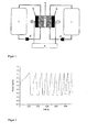
- FIG. 1 the basic structure of a redox flow battery with (a) an ion-conducting separator, (b) electrodes, (c) electrolyte containers, (d) electrolyte pumps, (e) electrical source / sink and (f) positive or negative half cell.
- ionic liquid is used in its usual meaning, i.
- Ionic liquids are understood as meaning organic, ionic compounds which are composed of an organic or inorganic anion and a voluminous organic cation. If the ionic liquid is molten below 100 ° C, it is called RTILs (Room Temperature Ionic Liquids).
- both (ie, the positive and negative) half cells of the redox flow battery contain an ionic liquid, which ionic liquids may be the same or different.
- the electrolyte contains less than 0.05% by weight of water, more preferably less than 0.02% by weight, even more preferably less than 0.01% by weight of water.
- the electrolyte is anhydrous.
- anhydrous electrolytes By using anhydrous electrolytes, a larger electrochemical potential window can be realized than with water-based redox flow batteries. Increasing the voltage increases the performance and energy density of the system.
- the electrolyte of the redox flow battery consists of at least 90% by weight, preferably at least 100% by weight, of the ionic liquid (s).
- phosphate such. Hexafluorophosphate, nitrite, nitrate, sulfate, e.g. Alkylsulfate, hydrogensulfate, carbonate, bicarbonate, phosphonate, phosphinate, sulfonate, e.g. Tosylate or methanesulfonate, carboxylate,
- Preferred anions may be exemplified by: fluoride, hexafluorophosphate, nitrite, nitrate, sulfate, hydrogensulfate, carbonate, hydrogencarbonate, phosphate, hydrogenphosphate, dihydrogenphosphate, vinylphosphonate, dicyanamide, bis (pentafluoroethyl) phosphinate, tris (pentafluoroethyl) trifluorophosphate, tris (heptafluoropropyl) trifluorophosphate, organic sulfonate of the general formula [R e -SO 3 ] - , wherein R e is a carbon-containing organic, saturated or unsaturated, acyclic or cyclic, aliphatic, aromatic or araliphatic radical having 1 to 30 carbon atoms containing one or more heteroatoms and or may be substituted by one or more functional groups or halogen,
- a carboxylate of the general formula [R f -COO] - wherein R f is hydrogen or a carbon-containing organic, saturated or unsaturated, acyclic or cyclic, aliphatic, aromatic or araliphatic radical having 1 to 30 carbon atoms containing one or more heteroatoms and or may be substituted by one or more functional groups or halogen, (Fluoroalkyl) fluorophosphate,
- R g to R l independently of one another are hydrogen or a carbon-containing organic, saturated or unsaturated, acyclic or cyclic, aliphatic, aromatic or araliphatic radical having 1 to 30 carbon atoms which contain one or more heteroatoms and / or by one or more a plurality of functional groups or halogen may be substituted;
- R m to R o are independently hydrogen or a carbon-containing organic, saturated or unsaturated, acyclic or cyclic, aliphatic, aromatic or araliphatic radical having 1 to 30 carbon atoms, which contain one or more heteroatoms and / or by one or more functional Groups or halogen may be substituted; organic sulfate of the general formula [R P O-SO 3 ] - , wherein R P is a carbon-containing organic, saturated or unsaturated, acyclic or cyclic, aliphatic, aromatic or araliphatic radical having 1 to 30 carbon atoms containing one or more heteroatoms and / or may be substituted by one or more functional groups or halogen.
- the cation of the ionic liquid (s) of imidazolium, pyridinium, pyrazolium, quinolinium, thiazolium, triazinium, pyrrolidinium, phosphonium, ammonium, sulfonium, or mixtures thereof is selected.
- Ionic liquids offer the possibility to dissolve redox couples and to use them as an electrolyte in redox flow batteries.
- the redox pair of V is preferable for the positive half-cell 4+ / V 5+, F 2 / F -, O 2 / O 2, O 3 / O 2, Ag 2+ / Ag +, Co 3+ / Co 2+ , N 2 O / N 2 , Ce 4+ / Ce 3+ , Au + / Au, Mn 7+ / Mn 4+ Ni 4+ / Ni 2+ , Mn 3+ / Mn 2+ , Pb 4+ / Pb 2+ , Au 3+ / Au + , Cl 2 / Cl - , Tl 3+ / Tl 2+ , Mn 4+ / Mn 2+ , Cu 2+ / Cu + , Pu 5+ / Pu 4+ , Br 2 / Br - , I 5+ / I - , Fe 3+ / Fe 2+ , Pu 4+ / Pu 3+ , Hg 2+ / Hg 2 2+ , Hg 2+ / Hg, U
- the redox flow battery is a vanadium redox flow battery, ie for the positive half cell, V 4+ / V 5+ is used as the redox couple and for the negative half cell V 3+ / V 2+ used as a redox couple.
- the vanadium redox flow battery has an operating temperature in the range of -30 ° C to 400 ° C, more preferably in the range of -20 ° C to 200 ° C. In a preferred embodiment, the operating temperature of the vanadium redox flow battery is above 40 ° C, more preferably above 50 ° C.
- the concentration of vanadium ions in the electrolyte is in the range of 0.1 mol / L to 10 mol / L, more preferably in the range of 0.1 mol / L to 5 mol / L , In a preferred In the embodiment, the concentration of vanadium ions in the electrolyte is above 2 mol / L, more preferably above 3 mol / L.
- Ionic liquids have melting and boiling points other than water and acids and bases dissolved in water. This results in other work areas that can not be achieved with aqueous electrolytes. Thus, operating temperatures well above the boiling point of water (100 ° C), concomitantly higher power densities can be achieved. Any cooling and monitoring devices can be omitted. Likewise, operating temperatures below freezing point of water (0 ° C) can be achieved with ionic liquids. This can be omitted any heating of the system.
- the redox couple is formed by the ionic liquid.
- Ionic liquids can themselves form the redox pairs. As a result, it is no longer necessary to dissolve substances as redox couples to the limit of their solubility in a liquid, but to use the solvent itself as the electrolyte and redox couple.
- the redox flow battery according to the invention has metallic electrodes.
- the metal is selected from iron, iron alloys, copper, copper alloys, nickel, nickel alloys, zinc, zinc alloys, silver, silver alloys, aluminum, aluminum alloys.
- ionic liquids with very low water content or anhydrous ionic liquids the decomposition of water can be completely or at least largely avoided.
- the potential window is within the decomposition of the ionic liquids.
- metallic electrodes can thus be used.
- the electrode is diamond or indium tin oxide (ITO). These electrode materials are chemically inert to a variety of materials, mechanically stable.
- the electrodes are either deposited on a suitable substrate by known coating techniques (e.g., CVD, PVD) or separately prepared and pressed with the substrate.
- CVD chemical vapor deposition
- PVD physical vapor deposition
- the last-mentioned variant is used when no coating processes are available for the desired substrate.
- Diamond electrodes are preferably doped with boron, nitrogen and / or phosphorus to set the desired electrical conductivity. By the Choice of dopant and the degree of doping, the electrical conductivity can be adjusted.
- the electrolyte of the redox flow battery according to the invention has no addition of stabilizers and / or acids or bases.
- Redox couples have different solubilities in ionic liquids than in aqueous systems. In addition, the solubilities are also very different from the ionic liquids. Redox couples can have a higher solubility in ionic liquids than would be possible in aqueous systems. Stabilizing agents or the addition of acids or bases can be omitted.
- the separator between the two half-cells is selected from NAFION; Fumasep FAP, FAD, FAB, FKE, FCS, FKB, FTCM-A, FTCM-E, FKL, FAA, FTAM-E, FTAM-A, FAS, FBM; microporous separators.
- the present invention relates to the use of an electrolyte containing an ionic liquid in a redox flow battery, wherein the anion of the ionic liquid (s) of halide, phosphate, nitrite, nitrate, sulfate, hydrogen sulfate, carbonate , Bicarbonate, phosphonate, phosphinate, sulfonate, carboxylate, imide, methide, or mixtures thereof; and the electrolyte is at least 90% by weight of the ionic liquid (s).
- 2-hydroxyethyl formate was used as the ionic liquid and inorganic salt solvent in a redox flow battery.
- VCl 3 vanadium (III) chloride
- the trivalent vanadium was electrolytically reduced or oxidized to V 2+ and V 4+ by means of a flow cell on carbon electrodes.
- Another solution of 0.5 mol of VCl 3 in 50 ml of 2-hydroxyethylammonium formate was used with the electrolytically prepared V 4+ solution as the starting electrolyte for the experiments on energy storage or energy removal.
- the V 3+ solution served as the anolyte and was pumped into the negative half cell of an electrochemical flow cell.
- the V 4+ solution served as the catholyte and was filled in the positive half cell of the flow cell.
- the solutions were not further pumped through the cell in the circulation.
- the cell was static with a max. Current density of 5 mA / cm 2 within the limits of 0.5V - 1.65V charged and discharged. Almost 9000 cycles were completed.
- FIG. 2 the voltage curve of the first 10 charging and discharging cycles is plotted.
- FIG. 3 the course of the discharge capacity, based on the first discharge capacity, the first 5000 charging and discharging cycles is shown.
- FIG. 2 shows the first ten charging and discharging curves of a stationary vanadium redox flow battery with 2-hydroxyethylammonium formate as solvent.
- the cell was charged galvanostatically with a constant current of 0.25 A up to a voltage of 1.65 V. Thereafter, the switching to the potentiostatic charging was carried out at a voltage of 1.65 V up to a current of 0.15 A. Subsequently, the discharge took place immediately. At a current strength 0.25 A, the battery was galvanostatically discharged to a voltage of 0.5 V. Thereafter, the potentiostatic discharge was carried out at a voltage of 0.5 V until a lower current limit of 0.15 A was reached.
- a step was carried out with the measurement of the clamping voltage for 60 seconds without load.
- the voltage of the battery increases to about 0.7 V.
- These charge / discharge cycles were as in FIG. 3 shown performed 5000 times. It is in FIG. 3 the capacity calculated from the current, voltage, and time measurements relative to the first discharge capacity.
- the discharge capacity of the first discharge in ampere-hours (Ah) was set to 1 and the discharge capacity of the following cycles related to the first value. During the first 1000 cycles, a large drop in the capacity can be seen, which subsequently recovers shortly after the initial value. Even after 5000 cycles, a capacity of approx. 20% of the output capacity can still be measured.
Landscapes
- Life Sciences & Earth Sciences (AREA)
- Engineering & Computer Science (AREA)
- Manufacturing & Machinery (AREA)
- Sustainable Development (AREA)
- Sustainable Energy (AREA)
- Chemical & Material Sciences (AREA)
- Chemical Kinetics & Catalysis (AREA)
- Electrochemistry (AREA)
- General Chemical & Material Sciences (AREA)
- Fuel Cell (AREA)
Applications Claiming Priority (2)
| Application Number | Priority Date | Filing Date | Title |
|---|---|---|---|
| DE102009009357A DE102009009357B4 (de) | 2009-02-18 | 2009-02-18 | Redox-Flow-Batterie zur Speicherung von elektrischer Energie in ionischen Flüssigkeiten |
| PCT/EP2010/051872 WO2010094657A1 (de) | 2009-02-18 | 2010-02-15 | Methode zur speicherung von elektrischer energie in ionischen flüssigkeiten |
Publications (2)
| Publication Number | Publication Date |
|---|---|
| EP2399317A1 EP2399317A1 (de) | 2011-12-28 |
| EP2399317B1 true EP2399317B1 (de) | 2015-04-08 |
Family
ID=42229119
Family Applications (1)
| Application Number | Title | Priority Date | Filing Date |
|---|---|---|---|
| EP10711357.3A Not-in-force EP2399317B1 (de) | 2009-02-18 | 2010-02-15 | Methode zur speicherung von elektrischer energie in ionischen flüssigkeiten |
Country Status (9)
| Country | Link |
|---|---|
| US (1) | US8802265B2 (enExample) |
| EP (1) | EP2399317B1 (enExample) |
| JP (1) | JP5468090B2 (enExample) |
| KR (2) | KR20140017017A (enExample) |
| CA (1) | CA2751982C (enExample) |
| DE (1) | DE102009009357B4 (enExample) |
| DK (1) | DK2399317T3 (enExample) |
| ES (1) | ES2539957T3 (enExample) |
| WO (1) | WO2010094657A1 (enExample) |
Families Citing this family (45)
| Publication number | Priority date | Publication date | Assignee | Title |
|---|---|---|---|---|
| US7820321B2 (en) | 2008-07-07 | 2010-10-26 | Enervault Corporation | Redox flow battery system for distributed energy storage |
| US8785023B2 (en) | 2008-07-07 | 2014-07-22 | Enervault Corparation | Cascade redox flow battery systems |
| AU2010341425B2 (en) | 2010-03-12 | 2012-11-15 | Sumitomo Electric Industries, Ltd. | Redox flow battery |
| DK2485312T3 (da) * | 2010-04-27 | 2013-10-14 | Sumitomo Electric Industries | Redox-flow-batteri |
| US9960443B2 (en) * | 2010-09-28 | 2018-05-01 | Battelle Memorial Institute | Redox flow batteries having multiple electroactive elements |
| US8628880B2 (en) | 2010-09-28 | 2014-01-14 | Battelle Memorial Institute | Redox flow batteries based on supporting solutions containing chloride |
| US8916281B2 (en) | 2011-03-29 | 2014-12-23 | Enervault Corporation | Rebalancing electrolytes in redox flow battery systems |
| US8980484B2 (en) | 2011-03-29 | 2015-03-17 | Enervault Corporation | Monitoring electrolyte concentrations in redox flow battery systems |
| CN102244285B (zh) * | 2011-05-24 | 2016-03-02 | 周成壁 | 一种高浓度锌钒氧化还原电池 |
| CN102856573A (zh) * | 2011-06-30 | 2013-01-02 | 中国科学院大连化学物理研究所 | 一种锌钒液流储能电池 |
| DE102011107185B3 (de) * | 2011-07-13 | 2012-08-16 | Fraunhofer-Gesellschaft zur Förderung der angewandten Forschung e.V. | Luftatmende Brennstoffzelle und Zellstapel für die Oxidation von Ionen mit Sauerstoff |
| US10003097B2 (en) * | 2011-08-02 | 2018-06-19 | Vizn Energy Systems, Incorporated | Process for operating a redox flow battery system |
| US9123943B1 (en) | 2011-08-04 | 2015-09-01 | Sandia Corporation | Synthesis of electroactive ionic liquids for flow battery applications |
| JP5780090B2 (ja) * | 2011-09-28 | 2015-09-16 | 凸版印刷株式会社 | 二次電池用の電極材料 |
| EP2862225A4 (en) | 2012-06-15 | 2015-12-30 | Univ Delaware | DESIGN OF A REDOX FLUX BATTERY WITH SEVERAL MEMBRANES AND SEVERAL ELECTRODES |
| US9537192B2 (en) * | 2012-08-01 | 2017-01-03 | Sharp Laboratories Of America, Inc. | Battery with low temperature molten salt (LTMS) cathode |
| KR102038619B1 (ko) | 2013-01-08 | 2019-10-30 | 삼성전자주식회사 | 레독스 플로우 전지 |
| CN105264704A (zh) | 2013-02-14 | 2016-01-20 | 海卓瑞道克斯技术控股有限公司 | 采用正电解质溶液中的氧化还原电对V+4/V+5和辅助氧化还原电对Ce+3/Ce+4的全钒氧化还原液流电池系统 |
| US8980454B2 (en) | 2013-03-15 | 2015-03-17 | Enervault Corporation | Systems and methods for rebalancing redox flow battery electrolytes |
| US10290889B2 (en) | 2013-08-07 | 2019-05-14 | Sumitomo Electric Industries, Ltd. | Redox flow battery |
| JP2016177868A (ja) * | 2013-08-07 | 2016-10-06 | 住友電気工業株式会社 | レドックスフロー電池 |
| DK3050149T3 (da) * | 2013-09-25 | 2023-07-24 | Lockheed Martin Energy Llc | Elektrolytbalancerende strategier til flowbatterier |
| KR102126034B1 (ko) | 2013-11-01 | 2020-06-23 | 삼성전자주식회사 | 이온 교환막, 그 제조방법 및 그것을 포함한 레독스 플로우 전지 |
| DE102013222716B4 (de) | 2013-11-08 | 2020-06-04 | Solarworld Industries Gmbh | Elektrochemischer Energiespeicher, Energiegewinnungsanlage und Verfahren zum Betrieb eines elektrochemischen Energiespeichers |
| KR102163726B1 (ko) | 2013-11-22 | 2020-10-08 | 삼성전자주식회사 | 레독스 플로우 전지 |
| US9748595B2 (en) * | 2013-11-25 | 2017-08-29 | Battelle Memorial Institute | High-energy-density, aqueous, metal-polyiodide redox flow batteries |
| CN103794813B (zh) * | 2014-03-07 | 2015-12-02 | 江西理工大学 | 铕铈液流电池 |
| DE102014103291A1 (de) | 2014-03-12 | 2015-09-17 | Schmid Energy Systems Gmbh | Elektrochemische Zelle und Verbund aus elektrochemischen Zellen |
| DE102014103286B4 (de) * | 2014-03-12 | 2022-10-27 | Schmid Energy Systems Gmbh | Seriell verschalteter Verbund aus Zellen, insbesondere für ein Redoxflow-Speichersystem, und Verfahren zu dessen Herstellung |
| DE102014103292A1 (de) | 2014-03-12 | 2015-09-17 | Schmid Energy Systems Gmbh | Verbund von elektrochemischen Zellen |
| CA2958909C (en) | 2014-10-06 | 2023-05-02 | Battelle Memorial Institute | All-vanadium sulfate acid redox flow battery system |
| JP2016164859A (ja) * | 2015-03-06 | 2016-09-08 | 古河電池株式会社 | バナジウムレドックス電池 |
| KR102127055B1 (ko) * | 2015-09-24 | 2020-06-26 | 주식회사 메디포럼제약 | 레독스흐름전지용 전해액을 위한 알킬기 치환된 이온성 액체 제조방법 |
| KR102003299B1 (ko) * | 2015-09-25 | 2019-07-24 | 주식회사 엘지화학 | 광재생 전지 |
| JP6682852B2 (ja) * | 2015-12-25 | 2020-04-15 | Jfeエンジニアリング株式会社 | レドックスフロー電池 |
| US10868332B2 (en) | 2016-04-01 | 2020-12-15 | NOHMs Technologies, Inc. | Modified ionic liquids containing phosphorus |
| FR3052598B1 (fr) * | 2016-06-10 | 2018-06-01 | Universite De Rennes 1 | Utilisation de liquides ioniques comme adjuvant en electrochimie |
| EP4087005A1 (en) | 2017-07-17 | 2022-11-09 | Nohms Technologies, Inc. | Phosphorus-containing electrolytes |
| JP2021121983A (ja) * | 2018-05-02 | 2021-08-26 | 昭和電工株式会社 | レドックスフロー電池の運転方法 |
| DE102018116293A1 (de) * | 2018-07-05 | 2020-01-09 | Albert-Ludwigs-Universität Freiburg | Flussbatterie |
| CN109638329A (zh) * | 2018-12-19 | 2019-04-16 | 中国科学技术大学 | 一种水系液流电池 |
| WO2020209274A1 (ja) | 2019-04-08 | 2020-10-15 | ARM Technologies株式会社 | レドックスフロー電池用負極電解液及びレドックスフロー電池 |
| DE102021126138A1 (de) | 2021-01-13 | 2022-07-14 | Schaeffler Technologies AG & Co. KG | Redox-Flussbatterie |
| WO2022152341A1 (de) | 2021-01-13 | 2022-07-21 | Schaeffler Technologies AG & Co. KG | Redox-flussbatterie |
| DE102022128209B4 (de) * | 2022-10-25 | 2024-05-02 | Fraunhofer-Gesellschaft zur Förderung der angewandten Forschung eingetragener Verein | Chlorid-freie Elektrolytzusammensetzung für einen längeren Betrieb bei hohen Temperaturen (>40°C) in Vanadium Redox-Flow-Batterien |
Family Cites Families (14)
| Publication number | Priority date | Publication date | Assignee | Title |
|---|---|---|---|---|
| US4786567A (en) | 1986-02-11 | 1988-11-22 | Unisearch Limited | All-vanadium redox battery |
| AU696452B2 (en) * | 1993-11-17 | 1998-09-10 | Jd Holding Inc. | Stabilised electrolyte solutions, methods of preparation thereof and redox cells and batteries containing stabilised electrolyte solutions |
| EP0829104B1 (en) * | 1995-05-03 | 2003-10-08 | Pinnacle VRB Limited | Method of preparing a high energy density vanadium electrolyte solution for all-vanadium redox cells and batteries |
| JP2001189156A (ja) * | 2000-01-06 | 2001-07-10 | Sumitomo Electric Ind Ltd | 電池用電極および電池 |
| DE10061959A1 (de) * | 2000-12-13 | 2002-06-20 | Creavis Tech & Innovation Gmbh | Kationen-/protonenleitende, mit einer ionischen Flüssigkeit infiltrierte keramische Membran, Verfahren zu deren Herstellung und die Verwendung der Membran |
| US7060169B2 (en) * | 2002-08-14 | 2006-06-13 | Mst Technology Gmbh | Electrochemical cell for gas sensor |
| JP2004111182A (ja) * | 2002-09-18 | 2004-04-08 | Sumitomo Electric Ind Ltd | レドックスフロー電池用電極の再賦活方法 |
| JP2004168560A (ja) * | 2002-11-15 | 2004-06-17 | Sumitomo Electric Ind Ltd | バナジウム化合物の生成方法及びバナジウム電解液の生成方法 |
| WO2005036573A1 (ja) * | 2003-10-09 | 2005-04-21 | Kaneka Corporation | 電極複合体および電解質、ならびにレドックスキャパシター |
| JP2007179745A (ja) * | 2004-08-26 | 2007-07-12 | Yokohama National Univ | プロトン伝導体 |
| JP5050847B2 (ja) * | 2005-05-31 | 2012-10-17 | パナソニック株式会社 | 二次電池とこれを用いた電源システム、電源システムの使用方法 |
| JP5158403B2 (ja) * | 2006-09-19 | 2013-03-06 | ソニー株式会社 | 燃料電池および燃料電池システム、並びに電子機器 |
| CN101675023B (zh) * | 2007-05-05 | 2014-10-29 | 巴斯夫欧洲公司 | 包含聚醚羧酸根作为阴离子的离子液体,其制备方法及其用途 |
| JP2010086935A (ja) | 2008-09-03 | 2010-04-15 | Sharp Corp | レドックスフロー電池 |
-
2009
- 2009-02-18 DE DE102009009357A patent/DE102009009357B4/de not_active Expired - Fee Related
-
2010
- 2010-02-15 DK DK10711357T patent/DK2399317T3/en active
- 2010-02-15 KR KR1020147000660A patent/KR20140017017A/ko not_active Withdrawn
- 2010-02-15 ES ES10711357.3T patent/ES2539957T3/es active Active
- 2010-02-15 JP JP2011549591A patent/JP5468090B2/ja not_active Expired - Fee Related
- 2010-02-15 KR KR1020117018958A patent/KR20110126623A/ko not_active Ceased
- 2010-02-15 WO PCT/EP2010/051872 patent/WO2010094657A1/de not_active Ceased
- 2010-02-15 EP EP10711357.3A patent/EP2399317B1/de not_active Not-in-force
- 2010-02-15 CA CA2751982A patent/CA2751982C/en not_active Expired - Fee Related
- 2010-02-15 US US13/201,813 patent/US8802265B2/en not_active Expired - Fee Related
Also Published As
| Publication number | Publication date |
|---|---|
| DE102009009357B4 (de) | 2011-03-03 |
| KR20140017017A (ko) | 2014-02-10 |
| JP5468090B2 (ja) | 2014-04-09 |
| DK2399317T3 (en) | 2015-04-27 |
| JP2012518247A (ja) | 2012-08-09 |
| ES2539957T3 (es) | 2015-07-07 |
| CA2751982A1 (en) | 2010-08-26 |
| CA2751982C (en) | 2014-03-25 |
| DE102009009357A1 (de) | 2010-09-02 |
| EP2399317A1 (de) | 2011-12-28 |
| KR20110126623A (ko) | 2011-11-23 |
| US20120115069A1 (en) | 2012-05-10 |
| US8802265B2 (en) | 2014-08-12 |
| WO2010094657A1 (de) | 2010-08-26 |
Similar Documents
| Publication | Publication Date | Title |
|---|---|---|
| EP2399317B1 (de) | Methode zur speicherung von elektrischer energie in ionischen flüssigkeiten | |
| EP3794666B9 (de) | Wiederaufladbare batteriezelle | |
| KR102818684B1 (ko) | 광범위한 전기화학적 안정성 윈도우가 있는 수성 및 혼성 전해질 | |
| DE3518859C2 (de) | Wiederaufladbare elektrochemische Hochtemperaturzelle und ein Verfahren zum Betrieb derselben | |
| DE2732332C2 (de) | Elektrochemische stromliefernde Zelle | |
| EP2659541B1 (de) | Lithium-schwefel-zelle auf festkörperelektrolytbasis | |
| DE102015105754B4 (de) | Fluoridionenbatterie | |
| EP3298642B1 (en) | Electrochemical cell | |
| DE2713780A1 (de) | Elektrochemische metall-halogen- zelle | |
| KR20170032884A (ko) | 다전자 수계 전지 | |
| DE3884572T2 (de) | Überladeschutz für nichtwässrige Sekundärbatterien. | |
| WO2017097594A1 (de) | Elektrodenmaterial, batteriezelle dieses enthaltend und verfahren zu deren herstellung | |
| WO2022162005A1 (de) | Auf so2-basierender elektrolyt für eine wiederaufladbare batteriezelle und wiederaufladbare batteriezelle | |
| DE112021003738T5 (de) | Wiederaufladbare metallhalogenidbatterie mit interkalationsanode | |
| JP2012009322A (ja) | 水系リチウムイオン二次電池 | |
| KR20170026574A (ko) | 배터리 | |
| Chen et al. | Aqueous Aluminium‐Ion Batteries: Cathode Material Design, Anode Engineering and Electrolyte Innovation | |
| WO2002071507A2 (de) | Wiederaufladbare nichtwässrige batteriezelle mit auf so2 basierendem elektrolytsystem | |
| AU2020243832A1 (en) | Carbon gel electrode | |
| Timofeeva et al. | Rechargeable nanoelectrofuel electrodes and devices for high energy density flow batteries | |
| WO2016045886A1 (de) | Elektrochemische zelle, elektrolyt geeignet zum befüllen derselben, verfahren zum herstellen derselben und verfahren zum betreiben derselben | |
| WO2025026495A1 (de) | Flüssige elektrolytzusammensetzung mit einem salz, elektrochemische zelle mit der elektrolytzusammensetzung, salz sowie verwendung des salzes in der elektrochemischen zelle | |
| DE102023136016A1 (de) | Elektrolytmembranen für batterien, die lithium-ionen zyklisieren, und verfahren zu deren herstellung | |
| DE3335454C2 (enExample) | ||
| EP3113275A1 (de) | Sekundäre magnesiumbatterie und elektrolytsystem sowie elektrode für eine sekundäre magnesiumbatterie |
Legal Events
| Date | Code | Title | Description |
|---|---|---|---|
| PUAI | Public reference made under article 153(3) epc to a published international application that has entered the european phase |
Free format text: ORIGINAL CODE: 0009012 |
|
| 17P | Request for examination filed |
Effective date: 20110915 |
|
| AK | Designated contracting states |
Kind code of ref document: A1 Designated state(s): AT BE BG CH CY CZ DE DK EE ES FI FR GB GR HR HU IE IS IT LI LT LU LV MC MK MT NL NO PL PT RO SE SI SK SM TR |
|
| DAX | Request for extension of the european patent (deleted) | ||
| 17Q | First examination report despatched |
Effective date: 20140310 |
|
| GRAP | Despatch of communication of intention to grant a patent |
Free format text: ORIGINAL CODE: EPIDOSNIGR1 |
|
| INTG | Intention to grant announced |
Effective date: 20141022 |
|
| GRAS | Grant fee paid |
Free format text: ORIGINAL CODE: EPIDOSNIGR3 |
|
| GRAA | (expected) grant |
Free format text: ORIGINAL CODE: 0009210 |
|
| AK | Designated contracting states |
Kind code of ref document: B1 Designated state(s): AT BE BG CH CY CZ DE DK EE ES FI FR GB GR HR HU IE IS IT LI LT LU LV MC MK MT NL NO PL PT RO SE SI SK SM TR |
|
| REG | Reference to a national code |
Ref country code: GB Ref legal event code: FG4D Free format text: NOT ENGLISH |
|
| REG | Reference to a national code |
Ref country code: CH Ref legal event code: EP |
|
| REG | Reference to a national code |
Ref country code: DK Ref legal event code: T3 Effective date: 20150423 |
|
| REG | Reference to a national code |
Ref country code: IE Ref legal event code: FG4D Free format text: LANGUAGE OF EP DOCUMENT: GERMAN |
|
| REG | Reference to a national code |
Ref country code: AT Ref legal event code: REF Ref document number: 721161 Country of ref document: AT Kind code of ref document: T Effective date: 20150515 Ref country code: CH Ref legal event code: NV Representative=s name: NIIZUMA WASNER GMBH PATENTANWALTSBUERO, CH |
|
| REG | Reference to a national code |
Ref country code: DE Ref legal event code: R096 Ref document number: 502010009299 Country of ref document: DE Effective date: 20150521 |
|
| REG | Reference to a national code |
Ref country code: SE Ref legal event code: TRGR |
|
| REG | Reference to a national code |
Ref country code: NL Ref legal event code: T3 |
|
| REG | Reference to a national code |
Ref country code: ES Ref legal event code: FG2A Ref document number: 2539957 Country of ref document: ES Kind code of ref document: T3 Effective date: 20150707 |
|
| REG | Reference to a national code |
Ref country code: LT Ref legal event code: MG4D |
|
| PG25 | Lapsed in a contracting state [announced via postgrant information from national office to epo] |
Ref country code: LT Free format text: LAPSE BECAUSE OF FAILURE TO SUBMIT A TRANSLATION OF THE DESCRIPTION OR TO PAY THE FEE WITHIN THE PRESCRIBED TIME-LIMIT Effective date: 20150408 Ref country code: FI Free format text: LAPSE BECAUSE OF FAILURE TO SUBMIT A TRANSLATION OF THE DESCRIPTION OR TO PAY THE FEE WITHIN THE PRESCRIBED TIME-LIMIT Effective date: 20150408 Ref country code: PT Free format text: LAPSE BECAUSE OF FAILURE TO SUBMIT A TRANSLATION OF THE DESCRIPTION OR TO PAY THE FEE WITHIN THE PRESCRIBED TIME-LIMIT Effective date: 20150810 Ref country code: HR Free format text: LAPSE BECAUSE OF FAILURE TO SUBMIT A TRANSLATION OF THE DESCRIPTION OR TO PAY THE FEE WITHIN THE PRESCRIBED TIME-LIMIT Effective date: 20150408 Ref country code: NO Free format text: LAPSE BECAUSE OF FAILURE TO SUBMIT A TRANSLATION OF THE DESCRIPTION OR TO PAY THE FEE WITHIN THE PRESCRIBED TIME-LIMIT Effective date: 20150708 |
|
| PG25 | Lapsed in a contracting state [announced via postgrant information from national office to epo] |
Ref country code: IS Free format text: LAPSE BECAUSE OF FAILURE TO SUBMIT A TRANSLATION OF THE DESCRIPTION OR TO PAY THE FEE WITHIN THE PRESCRIBED TIME-LIMIT Effective date: 20150808 Ref country code: GR Free format text: LAPSE BECAUSE OF FAILURE TO SUBMIT A TRANSLATION OF THE DESCRIPTION OR TO PAY THE FEE WITHIN THE PRESCRIBED TIME-LIMIT Effective date: 20150709 Ref country code: LV Free format text: LAPSE BECAUSE OF FAILURE TO SUBMIT A TRANSLATION OF THE DESCRIPTION OR TO PAY THE FEE WITHIN THE PRESCRIBED TIME-LIMIT Effective date: 20150408 |
|
| REG | Reference to a national code |
Ref country code: DE Ref legal event code: R097 Ref document number: 502010009299 Country of ref document: DE |
|
| PG25 | Lapsed in a contracting state [announced via postgrant information from national office to epo] |
Ref country code: EE Free format text: LAPSE BECAUSE OF FAILURE TO SUBMIT A TRANSLATION OF THE DESCRIPTION OR TO PAY THE FEE WITHIN THE PRESCRIBED TIME-LIMIT Effective date: 20150408 |
|
| PLBE | No opposition filed within time limit |
Free format text: ORIGINAL CODE: 0009261 |
|
| STAA | Information on the status of an ep patent application or granted ep patent |
Free format text: STATUS: NO OPPOSITION FILED WITHIN TIME LIMIT |
|
| REG | Reference to a national code |
Ref country code: FR Ref legal event code: PLFP Year of fee payment: 7 |
|
| PG25 | Lapsed in a contracting state [announced via postgrant information from national office to epo] |
Ref country code: RO Free format text: LAPSE BECAUSE OF NON-PAYMENT OF DUE FEES Effective date: 20150408 Ref country code: SK Free format text: LAPSE BECAUSE OF FAILURE TO SUBMIT A TRANSLATION OF THE DESCRIPTION OR TO PAY THE FEE WITHIN THE PRESCRIBED TIME-LIMIT Effective date: 20150408 Ref country code: CZ Free format text: LAPSE BECAUSE OF FAILURE TO SUBMIT A TRANSLATION OF THE DESCRIPTION OR TO PAY THE FEE WITHIN THE PRESCRIBED TIME-LIMIT Effective date: 20150408 Ref country code: PL Free format text: LAPSE BECAUSE OF FAILURE TO SUBMIT A TRANSLATION OF THE DESCRIPTION OR TO PAY THE FEE WITHIN THE PRESCRIBED TIME-LIMIT Effective date: 20150408 |
|
| REG | Reference to a national code |
Ref country code: DE Ref legal event code: R082 Ref document number: 502010009299 Country of ref document: DE |
|
| 26N | No opposition filed |
Effective date: 20160111 |
|
| PG25 | Lapsed in a contracting state [announced via postgrant information from national office to epo] |
Ref country code: SI Free format text: LAPSE BECAUSE OF FAILURE TO SUBMIT A TRANSLATION OF THE DESCRIPTION OR TO PAY THE FEE WITHIN THE PRESCRIBED TIME-LIMIT Effective date: 20150408 Ref country code: BE Free format text: LAPSE BECAUSE OF NON-PAYMENT OF DUE FEES Effective date: 20160229 |
|
| PG25 | Lapsed in a contracting state [announced via postgrant information from national office to epo] |
Ref country code: MC Free format text: LAPSE BECAUSE OF FAILURE TO SUBMIT A TRANSLATION OF THE DESCRIPTION OR TO PAY THE FEE WITHIN THE PRESCRIBED TIME-LIMIT Effective date: 20150408 Ref country code: LU Free format text: LAPSE BECAUSE OF FAILURE TO SUBMIT A TRANSLATION OF THE DESCRIPTION OR TO PAY THE FEE WITHIN THE PRESCRIBED TIME-LIMIT Effective date: 20160215 |
|
| REG | Reference to a national code |
Ref country code: IE Ref legal event code: MM4A |
|
| PG25 | Lapsed in a contracting state [announced via postgrant information from national office to epo] |
Ref country code: IE Free format text: LAPSE BECAUSE OF NON-PAYMENT OF DUE FEES Effective date: 20160215 |
|
| REG | Reference to a national code |
Ref country code: FR Ref legal event code: PLFP Year of fee payment: 8 |
|
| PGFP | Annual fee paid to national office [announced via postgrant information from national office to epo] |
Ref country code: SE Payment date: 20170221 Year of fee payment: 8 Ref country code: FR Payment date: 20170220 Year of fee payment: 8 Ref country code: DE Payment date: 20170222 Year of fee payment: 8 Ref country code: CH Payment date: 20170221 Year of fee payment: 8 |
|
| PGFP | Annual fee paid to national office [announced via postgrant information from national office to epo] |
Ref country code: DK Payment date: 20170222 Year of fee payment: 8 Ref country code: AT Payment date: 20170217 Year of fee payment: 8 Ref country code: GB Payment date: 20170221 Year of fee payment: 8 Ref country code: NL Payment date: 20170220 Year of fee payment: 8 |
|
| PGFP | Annual fee paid to national office [announced via postgrant information from national office to epo] |
Ref country code: IT Payment date: 20170217 Year of fee payment: 8 Ref country code: ES Payment date: 20170220 Year of fee payment: 8 |
|
| PG25 | Lapsed in a contracting state [announced via postgrant information from national office to epo] |
Ref country code: MT Free format text: LAPSE BECAUSE OF FAILURE TO SUBMIT A TRANSLATION OF THE DESCRIPTION OR TO PAY THE FEE WITHIN THE PRESCRIBED TIME-LIMIT Effective date: 20150408 |
|
| PG25 | Lapsed in a contracting state [announced via postgrant information from national office to epo] |
Ref country code: SM Free format text: LAPSE BECAUSE OF FAILURE TO SUBMIT A TRANSLATION OF THE DESCRIPTION OR TO PAY THE FEE WITHIN THE PRESCRIBED TIME-LIMIT Effective date: 20150408 Ref country code: CY Free format text: LAPSE BECAUSE OF FAILURE TO SUBMIT A TRANSLATION OF THE DESCRIPTION OR TO PAY THE FEE WITHIN THE PRESCRIBED TIME-LIMIT Effective date: 20150408 Ref country code: HU Free format text: LAPSE BECAUSE OF FAILURE TO SUBMIT A TRANSLATION OF THE DESCRIPTION OR TO PAY THE FEE WITHIN THE PRESCRIBED TIME-LIMIT; INVALID AB INITIO Effective date: 20100215 |
|
| PG25 | Lapsed in a contracting state [announced via postgrant information from national office to epo] |
Ref country code: TR Free format text: LAPSE BECAUSE OF FAILURE TO SUBMIT A TRANSLATION OF THE DESCRIPTION OR TO PAY THE FEE WITHIN THE PRESCRIBED TIME-LIMIT Effective date: 20150408 Ref country code: MK Free format text: LAPSE BECAUSE OF FAILURE TO SUBMIT A TRANSLATION OF THE DESCRIPTION OR TO PAY THE FEE WITHIN THE PRESCRIBED TIME-LIMIT Effective date: 20150408 |
|
| PG25 | Lapsed in a contracting state [announced via postgrant information from national office to epo] |
Ref country code: BG Free format text: LAPSE BECAUSE OF FAILURE TO SUBMIT A TRANSLATION OF THE DESCRIPTION OR TO PAY THE FEE WITHIN THE PRESCRIBED TIME-LIMIT Effective date: 20150408 |
|
| REG | Reference to a national code |
Ref country code: DE Ref legal event code: R119 Ref document number: 502010009299 Country of ref document: DE |
|
| REG | Reference to a national code |
Ref country code: CH Ref legal event code: PL |
|
| REG | Reference to a national code |
Ref country code: DK Ref legal event code: EBP Effective date: 20180228 |
|
| REG | Reference to a national code |
Ref country code: SE Ref legal event code: EUG |
|
| REG | Reference to a national code |
Ref country code: NL Ref legal event code: MM Effective date: 20180301 |
|
| REG | Reference to a national code |
Ref country code: AT Ref legal event code: MM01 Ref document number: 721161 Country of ref document: AT Kind code of ref document: T Effective date: 20180215 |
|
| GBPC | Gb: european patent ceased through non-payment of renewal fee |
Effective date: 20180215 |
|
| PG25 | Lapsed in a contracting state [announced via postgrant information from national office to epo] |
Ref country code: SE Free format text: LAPSE BECAUSE OF NON-PAYMENT OF DUE FEES Effective date: 20180216 |
|
| PG25 | Lapsed in a contracting state [announced via postgrant information from national office to epo] |
Ref country code: AT Free format text: LAPSE BECAUSE OF NON-PAYMENT OF DUE FEES Effective date: 20180215 Ref country code: LI Free format text: LAPSE BECAUSE OF NON-PAYMENT OF DUE FEES Effective date: 20180228 Ref country code: CH Free format text: LAPSE BECAUSE OF NON-PAYMENT OF DUE FEES Effective date: 20180228 |
|
| REG | Reference to a national code |
Ref country code: FR Ref legal event code: ST Effective date: 20181031 |
|
| PG25 | Lapsed in a contracting state [announced via postgrant information from national office to epo] |
Ref country code: NL Free format text: LAPSE BECAUSE OF NON-PAYMENT OF DUE FEES Effective date: 20180301 |
|
| PG25 | Lapsed in a contracting state [announced via postgrant information from national office to epo] |
Ref country code: DK Free format text: LAPSE BECAUSE OF NON-PAYMENT OF DUE FEES Effective date: 20180228 Ref country code: DE Free format text: LAPSE BECAUSE OF NON-PAYMENT OF DUE FEES Effective date: 20180901 |
|
| PG25 | Lapsed in a contracting state [announced via postgrant information from national office to epo] |
Ref country code: GB Free format text: LAPSE BECAUSE OF NON-PAYMENT OF DUE FEES Effective date: 20180215 Ref country code: FR Free format text: LAPSE BECAUSE OF NON-PAYMENT OF DUE FEES Effective date: 20180228 Ref country code: IT Free format text: LAPSE BECAUSE OF NON-PAYMENT OF DUE FEES Effective date: 20180215 |
|
| REG | Reference to a national code |
Ref country code: ES Ref legal event code: FD2A Effective date: 20190801 |
|
| PG25 | Lapsed in a contracting state [announced via postgrant information from national office to epo] |
Ref country code: ES Free format text: LAPSE BECAUSE OF NON-PAYMENT OF DUE FEES Effective date: 20180216 |