EP2399317B1 - Method for storing electrical energy in ionic liquids - Google Patents
Method for storing electrical energy in ionic liquids Download PDFInfo
- Publication number
- EP2399317B1 EP2399317B1 EP10711357.3A EP10711357A EP2399317B1 EP 2399317 B1 EP2399317 B1 EP 2399317B1 EP 10711357 A EP10711357 A EP 10711357A EP 2399317 B1 EP2399317 B1 EP 2399317B1
- Authority
- EP
- European Patent Office
- Prior art keywords
- flow battery
- redox flow
- redox
- electrolyte
- ionic liquid
- Prior art date
- Legal status (The legal status is an assumption and is not a legal conclusion. Google has not performed a legal analysis and makes no representation as to the accuracy of the status listed.)
- Not-in-force
Links
Images

Classifications
-
- H—ELECTRICITY
- H01—ELECTRIC ELEMENTS
- H01M—PROCESSES OR MEANS, e.g. BATTERIES, FOR THE DIRECT CONVERSION OF CHEMICAL ENERGY INTO ELECTRICAL ENERGY
- H01M8/00—Fuel cells; Manufacture thereof
- H01M8/18—Regenerative fuel cells, e.g. redox flow batteries or secondary fuel cells
- H01M8/184—Regeneration by electrochemical means
- H01M8/188—Regeneration by electrochemical means by recharging of redox couples containing fluids; Redox flow type batteries
-
- H—ELECTRICITY
- H01—ELECTRIC ELEMENTS
- H01M—PROCESSES OR MEANS, e.g. BATTERIES, FOR THE DIRECT CONVERSION OF CHEMICAL ENERGY INTO ELECTRICAL ENERGY
- H01M8/00—Fuel cells; Manufacture thereof
- H01M8/18—Regenerative fuel cells, e.g. redox flow batteries or secondary fuel cells
-
- H—ELECTRICITY
- H01—ELECTRIC ELEMENTS
- H01B—CABLES; CONDUCTORS; INSULATORS; SELECTION OF MATERIALS FOR THEIR CONDUCTIVE, INSULATING OR DIELECTRIC PROPERTIES
- H01B1/00—Conductors or conductive bodies characterised by the conductive materials; Selection of materials as conductors
- H01B1/06—Conductors or conductive bodies characterised by the conductive materials; Selection of materials as conductors mainly consisting of other non-metallic substances
-
- H—ELECTRICITY
- H01—ELECTRIC ELEMENTS
- H01M—PROCESSES OR MEANS, e.g. BATTERIES, FOR THE DIRECT CONVERSION OF CHEMICAL ENERGY INTO ELECTRICAL ENERGY
- H01M8/00—Fuel cells; Manufacture thereof
- H01M8/02—Details
-
- Y—GENERAL TAGGING OF NEW TECHNOLOGICAL DEVELOPMENTS; GENERAL TAGGING OF CROSS-SECTIONAL TECHNOLOGIES SPANNING OVER SEVERAL SECTIONS OF THE IPC; TECHNICAL SUBJECTS COVERED BY FORMER USPC CROSS-REFERENCE ART COLLECTIONS [XRACs] AND DIGESTS
- Y02—TECHNOLOGIES OR APPLICATIONS FOR MITIGATION OR ADAPTATION AGAINST CLIMATE CHANGE
- Y02E—REDUCTION OF GREENHOUSE GAS [GHG] EMISSIONS, RELATED TO ENERGY GENERATION, TRANSMISSION OR DISTRIBUTION
- Y02E60/00—Enabling technologies; Technologies with a potential or indirect contribution to GHG emissions mitigation
- Y02E60/30—Hydrogen technology
- Y02E60/50—Fuel cells
Definitions
- Electrical energy can be stored by various processes.
- One possibility is the conversion of electrical energy into chemical energy by chemical reactions on electrode surfaces by electric current.
- This type of energy storage is used technically in secondary batteries (accumulators) on a large scale.
- the U.S. Patent 4,786,567 relates to a vanadium redox battery as well as methods of charging and energy recovery using the vanadium redox battery.
- a secondary battery is an electrochemical cell that consists of two half-cells, which in turn are separated by an ion-conducting separator.
- the separator ensures a charge balance, but prevents the mass transfer between the half-cells.
- a reduction of the active substance takes place during the storage process, in the positive half cell an oxidation.
- electrons thus flow from the positive half-cell into the negative half-cell, in the discharge process in the opposite direction.
- electrolyte liquid substance or substance mixture, referred to as electrolyte, is necessary in both half-cells as the ion conductor.
- the electrode is the phase boundary between the electrical conductor and the ionic conductor.
- the active material may be the electrode itself, a substance dissolved in the electrolyte or substances stored in the electrode material.
- the active material consists of negative electrolyte (anolyte) and positive electrolyte (catholyte) of substances dissolved in the electrolyte
- the result is that in this type of battery the amount of energy and power can be scaled independently, since the electrolyte from reservoirs at the electrodes can be passed.
- This type of electrochemical energy storage is called the redox flow battery.
- the electrolyte of redox flow batteries typically consists of mineral acids or organic acids dissolved in water.
- a potential window of about -0.5 V to 1.2 V with graphite electrodes compared to a standard hydrogen electrode is possible. Beyond these limits, which are referred to as potential windows, decomposition of water, and thus the destruction of the water-based electrolyte, gas evolution and loss of efficiency begins.
- the total voltage of a water-based redox flow battery with graphite electrodes is thus limited to max. Limited to 1.7V.
- the energy density of redox flow batteries depends on the solubility of the redox couples. For the highest possible energy density, the redox pairs are at the limit of solubility in the electrolyte.
- One type of redox flow battery is the vanadium redox flow battery. The reaction equation of such a vanadium redox flow battery is as follows:
- vanadium In this electrochemical energy storage vanadium is used in different oxidation states in the positive (catholyte) and in the negative (anolyte) electrolyte.
- concentration of vanadium When using aqueous sulfuric acid as solvent, the concentration of vanadium is limited to about 1.6 mol / L. The reason for this is the limited solubility of divanadyl cations (VO 2 + ) in aqueous sulfuric acid.
- vanadium pentoxide forms as a function of time and the ratio of vanadyl / divanadyl cations (VO 2+ / VO 2 + ) from dissolved divanadyl cations (VO 2 + ) 2 O 5 ) in the catholyte, which is no longer available for the chemical reactions, thereby reducing power and capacity of the memory and causes a pressure increase in the catholyte by the filtering action of the graphite felt in the positive half-cell.
- the electrochemical potential window i. the voltage range between formation of oxygen and hydrogen, i. the decomposition (electrolysis) of water relative to the standard hydrogen electrode is dependent on the material of the electrode.
- Metallic electrodes usually have a much lower potential window than carbon-based electrodes made of graphite or form passivating, i. performance-reducing layers.
- the widest possible electrochemical potential window is needed to use the redox pairs, as already explained above, one resorts to carbon in its modifications diamond, graphite and glassy carbon. Pure graphite electrodes have much lower strength and electrical conductivity than metals.
- composite materials of graphite / polymer mixtures are used. The use of polymers, however, in turn leads to a reduction of the electrical conductivity and thus to performance losses due to resistance losses.
- the energy density of a redox flow battery depends directly on the solubility of the redox couples in the electrolyte.
- acids or bases are used as constituents of the electrolyte in higher concentrations or stabilizers added.
- the working temperature is limited to well below the boiling temperature of the electrolyte, since due to the rapidly increasing partial pressure of the electrolyte, a pressure build-up in the entire system begins, which can lead to leaks and the electrolyte can not participate in the reaction. Therefore, the currently used redox flow batteries can only be operated in a very limited temperature range.
- An object of the present invention is to provide a redox flow battery, in which the disadvantages described above are avoided as far as possible and an improved variability in the selection of operating parameters such as operating temperature or choice of electrode material is made possible.
- a redox flow battery comprising an electrolyte containing at least one ionic liquid, wherein the anion of the ionic liquid (s) of halide, phosphate, nitrite, nitrate, sulfate, Hydrogen sulfate, carbonate, bicarbonate, phosphonate, phosphinate, sulfonate, carboxylate, imide, methide, or mixtures thereof, and the electrolyte is at least 90% by weight of the ionic liquid (s).
- redox flow battery In the context of the present invention, the term "redox flow battery" is used in its usual meaning.
- the basic structure of a redox flow battery is known in the art.
- the redox flow battery stores electrical energy in chemical compounds and is therefore related to the accumulators.
- the two energy-storing electrolytes circulate in two separate circuits, between which a charge exchange is possible in the battery by means of a membrane or a separator.
- the electrolytes are stored outside the battery in separate tanks, which means that the stored energy no longer depends on the size of the cell, so energy and power can be scaled separately.
- the redox flow battery according to the invention therefore has a positive half cell, a negative half cell, a separator separating the two half cells, two electrodes, and two electrolyte containers located outside the cells.
- the separator provides charge balance, but prevents mass transfer between the half cells.
- the negative half cell takes place during the storage process, a reduction of the active substance, in the positive half-cell oxidation.
- electrons thus flow from the positive half-cell into the negative half-cell, in the discharge process in the opposite direction.
- FIG. 1 the basic structure of a redox flow battery with (a) an ion-conducting separator, (b) electrodes, (c) electrolyte containers, (d) electrolyte pumps, (e) electrical source / sink and (f) positive or negative half cell.
- ionic liquid is used in its usual meaning, i.
- Ionic liquids are understood as meaning organic, ionic compounds which are composed of an organic or inorganic anion and a voluminous organic cation. If the ionic liquid is molten below 100 ° C, it is called RTILs (Room Temperature Ionic Liquids).
- both (ie, the positive and negative) half cells of the redox flow battery contain an ionic liquid, which ionic liquids may be the same or different.
- the electrolyte contains less than 0.05% by weight of water, more preferably less than 0.02% by weight, even more preferably less than 0.01% by weight of water.
- the electrolyte is anhydrous.
- anhydrous electrolytes By using anhydrous electrolytes, a larger electrochemical potential window can be realized than with water-based redox flow batteries. Increasing the voltage increases the performance and energy density of the system.
- the electrolyte of the redox flow battery consists of at least 90% by weight, preferably at least 100% by weight, of the ionic liquid (s).
- phosphate such. Hexafluorophosphate, nitrite, nitrate, sulfate, e.g. Alkylsulfate, hydrogensulfate, carbonate, bicarbonate, phosphonate, phosphinate, sulfonate, e.g. Tosylate or methanesulfonate, carboxylate,
- Preferred anions may be exemplified by: fluoride, hexafluorophosphate, nitrite, nitrate, sulfate, hydrogensulfate, carbonate, hydrogencarbonate, phosphate, hydrogenphosphate, dihydrogenphosphate, vinylphosphonate, dicyanamide, bis (pentafluoroethyl) phosphinate, tris (pentafluoroethyl) trifluorophosphate, tris (heptafluoropropyl) trifluorophosphate, organic sulfonate of the general formula [R e -SO 3 ] - , wherein R e is a carbon-containing organic, saturated or unsaturated, acyclic or cyclic, aliphatic, aromatic or araliphatic radical having 1 to 30 carbon atoms containing one or more heteroatoms and or may be substituted by one or more functional groups or halogen,
- a carboxylate of the general formula [R f -COO] - wherein R f is hydrogen or a carbon-containing organic, saturated or unsaturated, acyclic or cyclic, aliphatic, aromatic or araliphatic radical having 1 to 30 carbon atoms containing one or more heteroatoms and or may be substituted by one or more functional groups or halogen, (Fluoroalkyl) fluorophosphate,
- R g to R l independently of one another are hydrogen or a carbon-containing organic, saturated or unsaturated, acyclic or cyclic, aliphatic, aromatic or araliphatic radical having 1 to 30 carbon atoms which contain one or more heteroatoms and / or by one or more a plurality of functional groups or halogen may be substituted;
- R m to R o are independently hydrogen or a carbon-containing organic, saturated or unsaturated, acyclic or cyclic, aliphatic, aromatic or araliphatic radical having 1 to 30 carbon atoms, which contain one or more heteroatoms and / or by one or more functional Groups or halogen may be substituted; organic sulfate of the general formula [R P O-SO 3 ] - , wherein R P is a carbon-containing organic, saturated or unsaturated, acyclic or cyclic, aliphatic, aromatic or araliphatic radical having 1 to 30 carbon atoms containing one or more heteroatoms and / or may be substituted by one or more functional groups or halogen.
- the cation of the ionic liquid (s) of imidazolium, pyridinium, pyrazolium, quinolinium, thiazolium, triazinium, pyrrolidinium, phosphonium, ammonium, sulfonium, or mixtures thereof is selected.
- Ionic liquids offer the possibility to dissolve redox couples and to use them as an electrolyte in redox flow batteries.
- the redox pair of V is preferable for the positive half-cell 4+ / V 5+, F 2 / F -, O 2 / O 2, O 3 / O 2, Ag 2+ / Ag +, Co 3+ / Co 2+ , N 2 O / N 2 , Ce 4+ / Ce 3+ , Au + / Au, Mn 7+ / Mn 4+ Ni 4+ / Ni 2+ , Mn 3+ / Mn 2+ , Pb 4+ / Pb 2+ , Au 3+ / Au + , Cl 2 / Cl - , Tl 3+ / Tl 2+ , Mn 4+ / Mn 2+ , Cu 2+ / Cu + , Pu 5+ / Pu 4+ , Br 2 / Br - , I 5+ / I - , Fe 3+ / Fe 2+ , Pu 4+ / Pu 3+ , Hg 2+ / Hg 2 2+ , Hg 2+ / Hg, U
- the redox flow battery is a vanadium redox flow battery, ie for the positive half cell, V 4+ / V 5+ is used as the redox couple and for the negative half cell V 3+ / V 2+ used as a redox couple.
- the vanadium redox flow battery has an operating temperature in the range of -30 ° C to 400 ° C, more preferably in the range of -20 ° C to 200 ° C. In a preferred embodiment, the operating temperature of the vanadium redox flow battery is above 40 ° C, more preferably above 50 ° C.
- the concentration of vanadium ions in the electrolyte is in the range of 0.1 mol / L to 10 mol / L, more preferably in the range of 0.1 mol / L to 5 mol / L , In a preferred In the embodiment, the concentration of vanadium ions in the electrolyte is above 2 mol / L, more preferably above 3 mol / L.
- Ionic liquids have melting and boiling points other than water and acids and bases dissolved in water. This results in other work areas that can not be achieved with aqueous electrolytes. Thus, operating temperatures well above the boiling point of water (100 ° C), concomitantly higher power densities can be achieved. Any cooling and monitoring devices can be omitted. Likewise, operating temperatures below freezing point of water (0 ° C) can be achieved with ionic liquids. This can be omitted any heating of the system.
- the redox couple is formed by the ionic liquid.
- Ionic liquids can themselves form the redox pairs. As a result, it is no longer necessary to dissolve substances as redox couples to the limit of their solubility in a liquid, but to use the solvent itself as the electrolyte and redox couple.
- the redox flow battery according to the invention has metallic electrodes.
- the metal is selected from iron, iron alloys, copper, copper alloys, nickel, nickel alloys, zinc, zinc alloys, silver, silver alloys, aluminum, aluminum alloys.
- ionic liquids with very low water content or anhydrous ionic liquids the decomposition of water can be completely or at least largely avoided.
- the potential window is within the decomposition of the ionic liquids.
- metallic electrodes can thus be used.
- the electrode is diamond or indium tin oxide (ITO). These electrode materials are chemically inert to a variety of materials, mechanically stable.
- the electrodes are either deposited on a suitable substrate by known coating techniques (e.g., CVD, PVD) or separately prepared and pressed with the substrate.
- CVD chemical vapor deposition
- PVD physical vapor deposition
- the last-mentioned variant is used when no coating processes are available for the desired substrate.
- Diamond electrodes are preferably doped with boron, nitrogen and / or phosphorus to set the desired electrical conductivity. By the Choice of dopant and the degree of doping, the electrical conductivity can be adjusted.
- the electrolyte of the redox flow battery according to the invention has no addition of stabilizers and / or acids or bases.
- Redox couples have different solubilities in ionic liquids than in aqueous systems. In addition, the solubilities are also very different from the ionic liquids. Redox couples can have a higher solubility in ionic liquids than would be possible in aqueous systems. Stabilizing agents or the addition of acids or bases can be omitted.
- the separator between the two half-cells is selected from NAFION; Fumasep FAP, FAD, FAB, FKE, FCS, FKB, FTCM-A, FTCM-E, FKL, FAA, FTAM-E, FTAM-A, FAS, FBM; microporous separators.
- the present invention relates to the use of an electrolyte containing an ionic liquid in a redox flow battery, wherein the anion of the ionic liquid (s) of halide, phosphate, nitrite, nitrate, sulfate, hydrogen sulfate, carbonate , Bicarbonate, phosphonate, phosphinate, sulfonate, carboxylate, imide, methide, or mixtures thereof; and the electrolyte is at least 90% by weight of the ionic liquid (s).
- 2-hydroxyethyl formate was used as the ionic liquid and inorganic salt solvent in a redox flow battery.
- VCl 3 vanadium (III) chloride
- the trivalent vanadium was electrolytically reduced or oxidized to V 2+ and V 4+ by means of a flow cell on carbon electrodes.
- Another solution of 0.5 mol of VCl 3 in 50 ml of 2-hydroxyethylammonium formate was used with the electrolytically prepared V 4+ solution as the starting electrolyte for the experiments on energy storage or energy removal.
- the V 3+ solution served as the anolyte and was pumped into the negative half cell of an electrochemical flow cell.
- the V 4+ solution served as the catholyte and was filled in the positive half cell of the flow cell.
- the solutions were not further pumped through the cell in the circulation.
- the cell was static with a max. Current density of 5 mA / cm 2 within the limits of 0.5V - 1.65V charged and discharged. Almost 9000 cycles were completed.
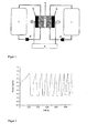
- FIG. 2 the voltage curve of the first 10 charging and discharging cycles is plotted.
- FIG. 3 the course of the discharge capacity, based on the first discharge capacity, the first 5000 charging and discharging cycles is shown.
- FIG. 2 shows the first ten charging and discharging curves of a stationary vanadium redox flow battery with 2-hydroxyethylammonium formate as solvent.
- the cell was charged galvanostatically with a constant current of 0.25 A up to a voltage of 1.65 V. Thereafter, the switching to the potentiostatic charging was carried out at a voltage of 1.65 V up to a current of 0.15 A. Subsequently, the discharge took place immediately. At a current strength 0.25 A, the battery was galvanostatically discharged to a voltage of 0.5 V. Thereafter, the potentiostatic discharge was carried out at a voltage of 0.5 V until a lower current limit of 0.15 A was reached.
- a step was carried out with the measurement of the clamping voltage for 60 seconds without load.
- the voltage of the battery increases to about 0.7 V.
- These charge / discharge cycles were as in FIG. 3 shown performed 5000 times. It is in FIG. 3 the capacity calculated from the current, voltage, and time measurements relative to the first discharge capacity.
- the discharge capacity of the first discharge in ampere-hours (Ah) was set to 1 and the discharge capacity of the following cycles related to the first value. During the first 1000 cycles, a large drop in the capacity can be seen, which subsequently recovers shortly after the initial value. Even after 5000 cycles, a capacity of approx. 20% of the output capacity can still be measured.
Description
Elektrische Energie kann durch verschiedene Prozesse gespeichert werden. Eine Möglichkeit ist die Umwandlung von elektrischer Energie in chemische Energie durch chemische Reaktionen an Elektrodenoberflächen durch elektrischen Strom. Diese Art der Energiespeicherung wird in sekundären Batterien (Akkumulatoren) in großem Umfang technisch genutzt.Electrical energy can be stored by various processes. One possibility is the conversion of electrical energy into chemical energy by chemical reactions on electrode surfaces by electric current. This type of energy storage is used technically in secondary batteries (accumulators) on a large scale.
In
Das
Eine sekundäre Batterie ist eine elektrochemische Zelle, die aus zwei Halbzellen besteht, die wiederum durch einen ionenleitenden Separator getrennt sind. Der Separator sorgt für einen Ladungsausgleich, verhindert aber den Stoffübergang zwischen den Halbzellen. In der negativen Halbzelle findet während des Speichervorgangs eine Reduktion des aktiven Stoffes statt, in der positiven Halbzelle eine Oxidation. Im Speichervorgang fließen somit Elektronen von der positiven Halbzelle in die negative Halbzelle, im Entladevorgang in umgekehrter Richtung.A secondary battery is an electrochemical cell that consists of two half-cells, which in turn are separated by an ion-conducting separator. The separator ensures a charge balance, but prevents the mass transfer between the half-cells. In the negative half cell, a reduction of the active substance takes place during the storage process, in the positive half cell an oxidation. In the storage process, electrons thus flow from the positive half-cell into the negative half-cell, in the discharge process in the opposite direction.
Um einen Ausgleich der Ladung und eine Bewegung der Ionen zu ermöglichen, ist in beiden Halbzellen als Ionenleiter ein flüssiger Stoff oder Stoffgemisch, als Elektrolyt bezeichnet, notwendig. Die Elektrode ist dabei die Phasengrenze zwischen elektrischem Leiter und ionischem Leiter. Das aktive Material kann die Elektrode selbst sein, ein im Elektrolyt gelöster Stoff oder in das Elektrodenmaterial eingelagerte Stoffe.In order to allow a compensation of the charge and a movement of the ions, a liquid substance or substance mixture, referred to as electrolyte, is necessary in both half-cells as the ion conductor. The electrode is the phase boundary between the electrical conductor and the ionic conductor. The active material may be the electrode itself, a substance dissolved in the electrolyte or substances stored in the electrode material.
Besteht das aktive Material von negativem Elektrolyt (Anolyt) und positivem Elektrolyt (Katholyt) aus im Elektrolyt gelösten Stoffen, dann entsteht der Fall, dass sich bei diesem Typ von Batterie Energiemenge und Leistung unabhängig voneinander skalieren lassen, da der Elektrolyt aus Vorratsbehältern an den Elektroden vorbeigeführt werden kann. Dieser Typ von elektrochemischem Energiespeicher wird Redox-Flow-Batterie genannt.If the active material consists of negative electrolyte (anolyte) and positive electrolyte (catholyte) of substances dissolved in the electrolyte, the result is that in this type of battery the amount of energy and power can be scaled independently, since the electrolyte from reservoirs at the electrodes can be passed. This type of electrochemical energy storage is called the redox flow battery.
Die allgemeinen chemischen Reaktionen sind folgende:
![]()
![]()
![]()
![]()
Der Elektrolyt von Redox-Flow-Batterien besteht typischerweise aus in Wasser gelösten Mineralsäuren oder organischen Säuren. Durch die Verwendung von Wasser als Bestandteil des Elektrolyts ist ein Potentialfenster von ca. -0,5 V bis 1,2 V mit Graphitelektroden gegenüber einer Standardwasserstoffelektrode möglich. Jenseits dieser als Potentialfenster bezeichneten Grenzen setzt eine Zersetzung von Wasser und damit die Zerstörung des wasserbasierten Elektrolyten, Gasentwicklung und Wirkungsgradverlust ein. Die Gesamtspannung einer wasserbasierten Redox-Flow-Batterie mit Graphitelektroden ist damit auf max. 1,7 V begrenzt.The electrolyte of redox flow batteries typically consists of mineral acids or organic acids dissolved in water. By using water as a constituent of the electrolyte, a potential window of about -0.5 V to 1.2 V with graphite electrodes compared to a standard hydrogen electrode is possible. Beyond these limits, which are referred to as potential windows, decomposition of water, and thus the destruction of the water-based electrolyte, gas evolution and loss of efficiency begins. The total voltage of a water-based redox flow battery with graphite electrodes is thus limited to max. Limited to 1.7V.
Es existieren jedoch Kombinationen aus Redoxpaaren, bei der sich eine höhere Spannung als 1,7 V einstellt. Um diese Kombinationen von Redoxpaaren als elektrochemischen Energiespeicher nutzen zu können, müssen nichtwässrige Elektrolyte eingesetzt werden, so wie es mit organischen Säuren möglich ist oder neue Elektrodenmaterialien mit höherem Potentialfenster gefunden werden. Einhergehend mit der Erhöhung der Spannung ist durch P = U*I eine steigende Leistungsdichte und durch W=U*I*t eine steigende Energiedichte möglich.However, there are combinations of redox pairs in which a higher voltage than 1.7 V is established. In order to use these combinations of redox couples as electrochemical energy storage, non-aqueous electrolytes must be used, as it is possible with organic acids or new electrode materials are found with a higher potential window. As the voltage increases, P = U * I increases the power density and W = U * I * t increases the energy density.
Die Energiedichte von Redox-Flow-Batterien ist abhängig von der Löslichkeit der Redoxpaare. Für eine möglichst hohe Energiedichte befinden sich die Redoxpaare an der Grenze der Löslichkeit im Elektrolyt. Ein Typ von Redox-Flow-Batterie ist die Vanadium-Redox-Flow-Batterie. Die Reaktionsgleichung einer solchen Vanadium-Redox-Flow-Batterie lautet wie folgt:

Bei diesem elektrochemischen Energiespeicher wird Vanadium in unterschiedlichen Oxidationsstufen im positiven (Katholyt) sowie im negativen (Anolyt) Elektrolyt verwendet. Bei Verwendung von wässriger Schwefelsäure als Lösungsmittel ist die Konzentration des Vanadium auf ca. 1,6 mol/L begrenzt. Der Grund hierfür liegt in der begrenzten Löslichkeit von Divanadyl-Kationen (VO2 +) in wässriger Schwefelsäure. Bei Temperaturen oberhalb von 40°C bildet sich nach der Gleichung in Abhängigkeit von der Zeit und dem Verhältnis an Vanadyl-/Divanadyl-Kationen (VO2+/VO2 +) aus gelösten Divanadyl-Kationen (VO2 +) festes Vanadiumpentoxid (V2O5) im Katholyt, das für die chemischen Reaktionen nicht mehr zur Verfügung steht, dadurch Leistung und Kapazität des Speichers verringert und einen Druckanstieg im Katholyten durch die filtrierende Wirkung des Graphitfilzes in der positiven Halbzelle bewirkt.
![]()
![]()
Divanadyl-Kationen (VO2 +) entstehen in einer Vanadium-Redox-Flow-Batterie während des Ladevorgangs nach folgender Reaktionsgleichung:

In wässrigen Systemen besitzt Kohlenstoff in seinen Modifikationen Diamant, Graphit sowie Glaskohlenstoff ein großes elektrochemisches Potentialfenster. Elektrodenmaterialen mit vergleichbarem Potentialfenster dürfen keine passivierenden Schichten oder Nebenreaktionen eingehen. Aus diesem Grund werden in Redox-Flow-Batterien üblicherweise Graphitelektroden eingesetzt, um eine Zersetzung von Wasser zu verhindern. Andererseits werden organische Säuren wie z.B. Methansulfonsäure als Elektrolytbestandteil eingesetzt, um Redoxpaar-Kombinationen jenseits der Grenze von 1,7 V einsetzten zu können.In aqueous systems, carbon has a large electrochemical potential window in its diamond, graphite, and glassy carbon modifications. Electrode materials with a comparable potential window must not undergo passivating layers or side reactions. For this reason, graphite electrodes are commonly used in redox flow batteries to prevent decomposition of water. On the other hand, organic acids such as e.g. Methanesulfonic acid used as an electrolyte component in order to use redox couple combinations beyond the limit of 1.7 V can.
Das elektrochemische Potentialfenster, d.h. der Spannungsbereich zwischen Bildung von Sauerstoff und Wasserstoff, d.h. der Zersetzung (Elektrolyse) von Wasser in Bezug zur Standardwasserstoffelektrode ist vom Material der Elektrode abhängig. Metallische Elektroden weisen meist ein wesentlich niedrigeres Potentialfenster auf als kohlenstoffbasierte Elektroden aus Graphit oder bilden passivierende, d.h. leistungsmindernde Schichten. Da jedoch ein möglichst breites elektrochemisches Potentialfenster zu Verwendung der Redoxpaare benötigt wird, greift man, wie oben bereits erläutert, auf Kohlenstoff in seinen Modifikationen Diamant, Graphit sowie Glaskohlenstoff zurück. Reine Graphitelektroden besitzen gegenüber Metallen eine wesentlich geringere Festigkeit und elektrische Leitfähigkeit. Zur Erhöhung der Stabilität werden Kompositmaterialien aus Graphit/Polymergemischen genutzt. Die Verwendung von Polymeren führt aber wiederum zu einer Verringerung der elektrischen Leitfähigkeit und damit zu Leistungseinbußen durch Widerstandsverluste.The electrochemical potential window, i. the voltage range between formation of oxygen and hydrogen, i. the decomposition (electrolysis) of water relative to the standard hydrogen electrode is dependent on the material of the electrode. Metallic electrodes usually have a much lower potential window than carbon-based electrodes made of graphite or form passivating, i. performance-reducing layers. However, since the widest possible electrochemical potential window is needed to use the redox pairs, as already explained above, one resorts to carbon in its modifications diamond, graphite and glassy carbon. Pure graphite electrodes have much lower strength and electrical conductivity than metals. To increase the stability composite materials of graphite / polymer mixtures are used. The use of polymers, however, in turn leads to a reduction of the electrical conductivity and thus to performance losses due to resistance losses.
Generell hängt die Energiedichte einer Redox-Flow-Batterie unmittelbar von der Löslichkeit der Redoxpaare in dem Elektrolyten ab. Um die Löslichkeit zu erhöhen, werden Säuren oder Basen als Bestandteile des Elektrolyten in höheren Konzentrationen eingesetzt oder Stabilisierungsmittel zugegeben.In general, the energy density of a redox flow battery depends directly on the solubility of the redox couples in the electrolyte. To increase the solubility, acids or bases are used as constituents of the electrolyte in higher concentrations or stabilizers added.
Wie oben bereits diskutiert, stellt die Ausfällung von Vanadiumpentoxid bei Vanadium-Redox-Flow-Batterien ein Problem dar. Um solche Ausfällungen von Vanadiumpentoxid zu verhindern, werden im Stand der Technik üblicherweise vier Maßnahmen angewendet.
- 1. Die Arbeitstemperatur des Batteriesystems wird zwischen 0°C < T < 40°C festgelegt. Bei T < 0°C beginnt der wässrige Elektrolyt in den festen Aggregatzustand überzugehen, wobei die Viskosität des Elektrolyts vom Arbeitsbereich mit sinkender Temperatur zunimmt. Ein Gefrieren des Elektrolyts bewirkt eine Zerstörung der Batterie. Bei Temperaturen über 40°C entstehen irreversible Ausfällungen von festem Vanadiumpentoxid. Eine Einschränkung der Temperatur in diesem Arbeitsbereich bedeutet eine Temperaturüberwachung und -regelung der Anlage. Einerseits muss durch z.B. Heizung gewährleistet werden, dass der Elektrolyt nicht einfriert und damit die Anlage zerstört wird und andererseits darf die Temperatur im Reaktionsraum nicht über 40°C ansteigen. Dies muss gegebenenfalls durch Kühlung gewährleistet werden.
- 2. Die Ausfällung von festem Vanadiumpentoxid ist von dem Verhältnis an Vanadyl-/Divanadyl-Kationen abhängig. Je höher die Konzentration an Divanadyl-Kationen ist, die beim Ladevorgang zunimmt, desto höher ist die Wahrscheinlichkeit des Ausfallens von festem Vanadiumpentoxid auch innerhalb der Temperaturgrenzen von 0°C < T < 40°C. Aus diesem Grund wird bei einer Vanadiumkonzentration > 1,6 mol/L im Ladevorgang nur bis zu ca. 80% der Vanadyl-Kationen zu Divanadyl-Kationen umgesetzt, entsprechend einem Ladungszustand von 80%.
- 3. Die standardmäßige Konzentration des Vanadiumelektrolyts ist 1,6 mol/L in 3 M Schwefelsäure (H2SO4). Dies bildet einen Kompromiss zwischen erhöhter Viskosität bei höheren Schwefelsäurekonzentrationen (erhöhter Energieaufwand für Pumpen, damit Wirkungsgradverlust) und Energiedichte. In den Temperaturgrenzen wird das Ausfallen von Vanadiumpentoxid durch ca. 0,05 mol/L Phosphorsäure verhindert.
- 4. Durch eine Erhöhung der Konzentration an Schwefelsäure im Elektrolyt ist eine geringfügig höhere Löslichkeit an Vanadyl-/Divanadyl-Kationen möglich. Die Grenzen hierbei liegen bei ca. 2 M Vanadium in 4-5 M Schwefelsäure.
- 1. The working temperature of the battery system is set between 0 ° C <T <40 ° C. At T <0 ° C, the aqueous electrolyte begins to transition to the solid state, with the viscosity of the electrolyte increasing from the operating region as the temperature decreases. A freezing of the electrolyte causes a destruction of the battery. At temperatures above 40 ° C, irreversible precipitations of solid vanadium pentoxide are formed. A limitation of the temperature in this work area means a temperature monitoring and control of the system. On the one hand, it must be ensured, for example by heating, that the electrolyte does not freeze and thus the system is destroyed and, on the other hand, the temperature in the reaction space must not rise above 40 ° C. If necessary, this must be ensured by cooling.
- 2. The precipitation of solid vanadium pentoxide is dependent on the ratio of vanadyl / divanadyl cations. The higher the concentration of divanadyl cations which increases during charging, the higher the probability of precipitation of solid vanadium pentoxide even within the temperature limits of 0 ° C <T <40 ° C. For this reason, only about 80% of the vanadyl cations are converted to divanadyl cations at a vanadium concentration> 1.6 mol / L during the charging process, corresponding to a charge state of 80%.
- 3. The standard concentration of vanadium electrolyte is 1.6 mol / L in 3 M sulfuric acid (H 2 SO 4 ). This forms a compromise between increased viscosity at higher sulfuric acid concentrations (increased energy expenditure for pumps, hence loss of efficiency) and energy density. In the temperature limits the precipitation of vanadium pentoxide is prevented by about 0.05 mol / L phosphoric acid.
- 4. By increasing the concentration of sulfuric acid in the electrolyte, a slightly higher solubility of vanadyl / divanadyl cations is possible. The limits here are about 2 M vanadium in 4-5 M sulfuric acid.
Die oben geschilderten Maßnahmen führen daher zu Beeinträchtigungen beim Betrieb einer Vanadium-Redox-Flow-Batterie.The above-described measures therefore lead to impairments in the operation of a vanadium redox flow battery.
In diesem Zusammenhang ist auch zu berücksichtigen, dass gemäß der VAN'T HOFFSCHEN REGEL (RGT-Regel) bei einer Erhöhung der Temperatur um 10K die Reaktionsgeschwindigkeit von chemischen Reaktionen um etwa das Doppelte ansteigt. Eine Erhöhung der Reaktionsgeschwindigkeit ist mit einer Erhöhung der Leistungsdichte verbunden. Bei Redox-Flow-Batterien arbeitet man soweit möglich bei Temperaturen oberhalb der Raumtemperatur. Bei der Vanadium-Redox-Flow-Batterie ist man durch die Ausfällung von Vanadiumpentoxid auf eine Temperatur von maximal 40°C beschränkt.In this context, it should also be considered that according to the VAN'T HOFFSCHEN RULE (RGT Rule), as the temperature increases by 10K, the reaction rate of chemical reactions increases by about double. An increase in the reaction rate is associated with an increase in power density. As far as possible, redox flow batteries work at temperatures above room temperature. In the vanadium redox flow battery is limited by the precipitation of vanadium pentoxide to a temperature of 40 ° C maximum.
Generell ist die Arbeitstemperatur auf weit unterhalb der Siedetemperatur des Elektrolyten begrenzt, da durch den rasch ansteigenden Partialdruck des Elektrolyten ein Druckaufbau im gesamten System einsetzt, was zu Leckagen führen kann und der Elektrolyt nicht mehr an der Reaktion teilhaben kann. Daher können die derzeit üblichen Redox-Flow-Batterien nur in einem recht begrenzten Temperaturbereich betrieben werden.In general, the working temperature is limited to well below the boiling temperature of the electrolyte, since due to the rapidly increasing partial pressure of the electrolyte, a pressure build-up in the entire system begins, which can lead to leaks and the electrolyte can not participate in the reaction. Therefore, the currently used redox flow batteries can only be operated in a very limited temperature range.
Eine Aufgabe der vorliegenden Erfindung besteht in der Bereitstellung einer Redox-Flow-Batterie, bei der die oben beschriebenen Nachteile möglichst vermieden werden und eine verbesserte Variabilität bei der Auswahl der Betriebsparameter wie z.B. Betriebstemperatur oder Wahl des Elektrodenmaterials ermöglicht wird.An object of the present invention is to provide a redox flow battery, in which the disadvantages described above are avoided as far as possible and an improved variability in the selection of operating parameters such as operating temperature or choice of electrode material is made possible.
Gelöst wird diese Aufgabe gemäß der vorliegenden Erfindung durch die Bereitstellung einer Redox-Flow-Batterie, die einen Elektrolyten umfasst, der zumindest eine ionische Flüssigkeit enthält, wobei das Anion der ionischen Flüssigkeit(en) aus Halogenid, Phosphat, Nitrit, Nitrat, Sulfat, Hydrogensulfat, Carbonat, Hydrogencarbonat, Phosphonat, Phosphinat, Sulfonat, Carboxylat, Imid, Methid, oder deren Gemischen ausgewählt wird, und der Elektrolyt zu mindestens 90 Gew% aus der/den ionischen Flüssigkeit/en besteht.This object is achieved according to the present invention by providing a redox flow battery comprising an electrolyte containing at least one ionic liquid, wherein the anion of the ionic liquid (s) of halide, phosphate, nitrite, nitrate, sulfate, Hydrogen sulfate, carbonate, bicarbonate, phosphonate, phosphinate, sulfonate, carboxylate, imide, methide, or mixtures thereof, and the electrolyte is at least 90% by weight of the ionic liquid (s).
Im Rahmen der vorliegenden Erfindung wird der Begriff "Redox-Flow-Batterie" in seiner üblichen Bedeutung verwendet. Der prinzipielle Aufbau einer Redox-Flow-Batterie ist dem Fachmann bekannt.In the context of the present invention, the term "redox flow battery" is used in its usual meaning. The basic structure of a redox flow battery is known in the art.
Die Redox-Flow-Batterie speichert elektrische Energie in chemischen Verbindungen und ist daher mit den Akkumulatoren verwandt. Im Unterschied zu klassischen Akkumulatoren zirkulieren die zwei energiespeichernden Elektrolyte in zwei getrennten Kreisläufen, zwischen denen in der Batterie mittels einer Membran bzw. eines Separators ein Ladungsaustausch möglich wird. Die Elektrolyte werden außerhalb der Batterie in getrennten Behältern bzw. Tanks gelagert, wodurch die gespeicherte Energie nicht mehr von der Größe der Zelle abhängt, somit Energie und Leistung separat skaliert werden können.The redox flow battery stores electrical energy in chemical compounds and is therefore related to the accumulators. In contrast to classical accumulators, the two energy-storing electrolytes circulate in two separate circuits, between which a charge exchange is possible in the battery by means of a membrane or a separator. The electrolytes are stored outside the battery in separate tanks, which means that the stored energy no longer depends on the size of the cell, so energy and power can be scaled separately.
In Übereinstimmung mit einer herkömmlichen Redox-Flow-Batterie weist die erfindungsgemäße Redox-Flow-Batterie daher eine positive Halbzelle, eine negative Halbzelle, einen die beiden Halbzellen trennenden Separator, zwei Elektroden, sowie zwei außerhalb der Zellen befindliche Elektrolytbehälter auf.In accordance with a conventional redox flow battery, the redox flow battery according to the invention therefore has a positive half cell, a negative half cell, a separator separating the two half cells, two electrodes, and two electrolyte containers located outside the cells.
Wie bereits oben diskutiert, sorgt der Separator für einen Ladungsausgleich, verhindert aber den Stoffübergang zwischen den Halbzellen. In der negativen Halbzelle findet während des Speichervorgangs eine Reduktion des aktiven Stoffes statt, in der positiven Halbzelle eine Oxidation. Im Speichervorgang fließen somit Elektronen von der positiven Halbzelle in die negative Halbzelle, im Entladevorgang in umgekehrter Richtung.As discussed above, the separator provides charge balance, but prevents mass transfer between the half cells. In the negative half cell takes place during the storage process, a reduction of the active substance, in the positive half-cell oxidation. In the storage process, electrons thus flow from the positive half-cell into the negative half-cell, in the discharge process in the opposite direction.
Beispielhaft zeigt
Im Rahmen der vorliegenden Erfindung wird der Begriff "ionische Flüssigkeit" in seiner üblichen Bedeutung verwendet, d.h. unter ionischen Flüssigkeiten werden organische, ionische Verbindungen verstanden, die sich aus einem organischen oder anorganischen Anion und einem voluminösen organischen Kationen zusammensetzen. Liegt die Ionische Flüssigkeit unter 100 °C schmelzflüssig vor, spricht man von RTILs (Room Temperature Ionic Liquids).In the context of the present invention, the term "ionic liquid" is used in its usual meaning, i. Ionic liquids are understood as meaning organic, ionic compounds which are composed of an organic or inorganic anion and a voluminous organic cation. If the ionic liquid is molten below 100 ° C, it is called RTILs (Room Temperature Ionic Liquids).
Typische Eigenschaften ionischer Flüssigkeiten sind
- hohe chemische Stabilität,
- weites Potentialfenster (hohe elektrochemische Stabilität),
- hohe ionische Leitfähigkeit,
- geringer Dampfdruck,
- nicht brennbar,
- hohe thermische Stabilität.
- high chemical stability,
- wide potential window (high electrochemical stability),
- high ionic conductivity,
- low vapor pressure,
- non-flammable,
- high thermal stability.
Die große Variationsbreite der organischen Substituenten und die Vielzahl an Kombinationsmöglichkeiten von Anionen und Kationen erlauben es, die physikalisch-chemischen Eigenschaften ionischer Flüssigkeiten in einem weiten Bereich zu beeinflussen bzw. gezielt an Anwendungen anzupassen.The wide variety of organic substituents and the large number of possible combinations of anions and cations make it possible to influence the physical-chemical properties of ionic liquids in a wide range or to adapt them specifically to applications.
Bevorzugt enthalten beide (d.h. die positive und negative) Halbzellen der Redox-Flow-Batterie eine ionische Flüssigkeit, wobei die ionischen Flüssigkeiten gleich oder verschieden sein können.Preferably, both (ie, the positive and negative) half cells of the redox flow battery contain an ionic liquid, which ionic liquids may be the same or different.
In einer bevorzugten Ausführungsform enthält der Elektrolyt weniger als 0,05 Gew.-% Wasser, bevorzugter weniger als 0,02 Gew.-%, noch bevorzugter weniger als 0,01 Gew.-% Wasser.In a preferred embodiment, the electrolyte contains less than 0.05% by weight of water, more preferably less than 0.02% by weight, even more preferably less than 0.01% by weight of water.
Bevorzugt ist der Elektrolyt wasserfrei.Preferably, the electrolyte is anhydrous.
Durch die Verwendung von wasserfreien Elektrolyten ist ein größeres elektrochemisches Potentialfenster als bei wasserbasierten Redox-Flow-Batterien realisierbar. Mit Erhöhung der Spannung erhöhen sich die Leistung und die Energiedichte des Systems.By using anhydrous electrolytes, a larger electrochemical potential window can be realized than with water-based redox flow batteries. Increasing the voltage increases the performance and energy density of the system.
Erfindungsgemäß besteht der Elektrolyt der Redox-Flow-Batterie zu mindestens 90 Gew.-%, bevorzugt zu mindestens 100 Gew.-% aus der/den ionischen Flüssigkeit/en.According to the invention, the electrolyte of the redox flow battery consists of at least 90% by weight, preferably at least 100% by weight, of the ionic liquid (s).
Erfindungsgemäß wird das Anion der ionischen Flüssigkeit(en) aus Halogenid, Phosphat wie z.B. Hexafluorophosphat, Nitrit, Nitrat, Sulfat wie z.B. Alkylsulfat, Hydrogensulfat, Carbonat, Hydrogencarbonat, Phosphonat, Phosphinat, Sulfonat wie z.B. Tosylat oder Methansulfonat, Carboxylat wie z.B. Formiat, Imid wie z.B. bis(Trifluormethylsulfonyl)imid, Methid, oder deren Gemischen ausgewählt.According to the invention, the anion of the ionic liquid (s) of halide, phosphate such. Hexafluorophosphate, nitrite, nitrate, sulfate, e.g. Alkylsulfate, hydrogensulfate, carbonate, bicarbonate, phosphonate, phosphinate, sulfonate, e.g. Tosylate or methanesulfonate, carboxylate, e.g. Formate, imide, e.g. bis (trifluoromethylsulfonyl) imide, methide, or mixtures thereof.
Als bevorzugte Anionen können beispielhaft genannt werden: Fluorid, Hexafluorophosphat, Nitrit, Nitrat, Sulfat, Hydrogensulfat, Carbonat, Hydrogencarbonat, Phosphat, Hydrogenphosphat, Dihydrogenphosphat, Vinylphosphonat, Dicyanamid, Bis(pentafluoroethyl)phosphinat, Tris(pentafluoroethyl)trifluorophosphat, Tris(heptafluoropropyl)trifluorophosphat, organisches Sulfonat der allgemeinen Formel [Re-SO3]-, wobei Re für einen Kohlenstoff enthaltenden organischen, gesättigten oder ungesättigten, acyclischen oder cyclischen, aliphatischen, aromatischen oder araliphatischen Rest mit 1 bis 30 Kohlenstoffatomen, welcher ein oder mehrere Heteroatome enthalten und/oder durch eine oder mehrere funktionelle Gruppen oder Halogen substituiert sein kann, steht,Preferred anions may be exemplified by: fluoride, hexafluorophosphate, nitrite, nitrate, sulfate, hydrogensulfate, carbonate, hydrogencarbonate, phosphate, hydrogenphosphate, dihydrogenphosphate, vinylphosphonate, dicyanamide, bis (pentafluoroethyl) phosphinate, tris (pentafluoroethyl) trifluorophosphate, tris (heptafluoropropyl) trifluorophosphate, organic sulfonate of the general formula [R e -SO 3 ] - , wherein R e is a carbon-containing organic, saturated or unsaturated, acyclic or cyclic, aliphatic, aromatic or araliphatic radical having 1 to 30 carbon atoms containing one or more heteroatoms and or may be substituted by one or more functional groups or halogen,
Carboxylat der allgemeinen Formel [Rf-COO]-, wobei Rf für Wasserstoff oder einen Kohlenstoff enthaltenden organischen, gesättigten oder ungesättigten, acyclischen oder cyclischen, aliphatischen, aromatischen oder araliphatischen Rest mit 1 bis 30 Kohlenstoffatomen, welcher ein oder mehrere Heteroatome enthalten und/oder durch eine oder mehrere funktionelle Gruppen oder Halogen substituiert sein kann, steht,
(Fluoralkyl)fluorphosphat,A carboxylate of the general formula [R f -COO] - , wherein R f is hydrogen or a carbon-containing organic, saturated or unsaturated, acyclic or cyclic, aliphatic, aromatic or araliphatic radical having 1 to 30 carbon atoms containing one or more heteroatoms and or may be substituted by one or more functional groups or halogen,
(Fluoroalkyl) fluorophosphate,
Imid der allgemeinen Formeln [Rg-SO2-N-SO2-Rh]-, [Rj-SO2-N-CO-Rj]- oder [Rk-CO-N-CO-Rl]-, wobei Rg bis Rl unabhängig voneinander für Wasserstoff oder einen Kohlenstoff enthaltenden organischen, gesättigten oder ungesättigten, acyclischen oder cyclischen, aliphatischen, aromatischen oder araliphatischen Rest mit 1 bis 30 Kohlenstoffatomen, welcher ein oder mehrere Heteroatome enthalten und/oder durch eine oder mehrere funktionelle Gruppen oder Halogen substituiert sein kann, stehen;Imide of the general formulas [R g -SO 2 -N-SO 2 -R h ] - , [R j -SO 2 -N-CO-R j ] - or [R k -CO-N-CO-R l ] - , wherein R g to R l independently of one another are hydrogen or a carbon-containing organic, saturated or unsaturated, acyclic or cyclic, aliphatic, aromatic or araliphatic radical having 1 to 30 carbon atoms which contain one or more heteroatoms and / or by one or more a plurality of functional groups or halogen may be substituted;

organisches Sulfat der allgemeinen Formel [RPO-SO3]-, wobei RP für einen Kohlenstoff enthaltenden organischen, gesättigten oder ungesättigten, acyclischen oder cyclischen, aliphatischen, aromatischen oder araliphatischen Rest mit 1 bis 30 Kohlenstoffatomen, welcher ein oder mehrere Heteroatome enthalten und/oder durch eine oder mehrere funktionelle Gruppen oder Halogen substituiert sein kann, steht.
organic sulfate of the general formula [R P O-SO 3 ] - , wherein R P is a carbon-containing organic, saturated or unsaturated, acyclic or cyclic, aliphatic, aromatic or araliphatic radical having 1 to 30 carbon atoms containing one or more heteroatoms and / or may be substituted by one or more functional groups or halogen.
Bevorzugt wird das Kation der ionischen Flüssigkeit(en) aus Imidazolium, Pyridinium, Pyrazolium, Chinolinium, Thiazolium, Triazinium, Pyrrolidinium, Phosphonium, Ammonium, Sulfonium, oder deren Gemischen ausgewählt.Preferably, the cation of the ionic liquid (s) of imidazolium, pyridinium, pyrazolium, quinolinium, thiazolium, triazinium, pyrrolidinium, phosphonium, ammonium, sulfonium, or mixtures thereof is selected.
Als bevorzugte Kationen der ionischen Flüssigkeit können beispielhaft genannt werden:
- Quartäre Ammonium-Kationen der allgemeinen Formel [NR1R2R3R4]+, wobei R1, R2, R3, R4, die gleich oder unterschiedlich sein können, C1-12-Alkyl oder Phenyl-C1-4-Alkyl bedeuten, und/oder R1 und R2 zusammen für einen substituierten oder unsubstituierten C4-5-Alkenylenrest stehen;
- quartäre Phosphonium-Kationen der allgemeinen Formel [PR1R2R3R4]+, wobei R1, R2, R3, R4, die gleich oder unterschiedlich sein können, C1-12-Alkyl oder Phenyl-C1-4-Alkyl bedeuten, und/oder R1 und R2 zusammen für einen substituierten oder unsubstituierten C4-5-Alkenylenrest stehen;
- Quaternary ammonium cations of the general formula [NR 1 R 2 R 3 R 4 ] + , where R 1 , R 2 , R 3 , R 4 , which may be identical or different, are C 1-12 -alkyl or phenyl-C 1 -4- alkyl, and / or R1 and R2 together represent a substituted or unsubstituted C 4-5 alkenylene radical;
- quaternary phosphonium cations of the general formula [PR 1 R 2 R 3 R 4 ] + , where R 1 , R 2 , R 3 , R 4 , which can be identical or different, are C 1-12 -alkyl or phenyl-C 1 -4- alkyl, and / or R1 and R2 together represent a substituted or unsubstituted C 4-5 alkenylene radical;
Imidazolium-Kationen der allgemeinen Formel

Pyridinium-Kationen der allgemeinen Formel

Pyrazolium-Kationen der allgemeinen Formel

Chinolinium-Kationen der allgemeinen Formel

Thiazolium-Kationen der allgemeinen Formel

Triazinium-Kationen der allgemeinen Formel

- n ist 0, 1, 2, 3 oder 4;
- R ist Wasserstoff, C1-12-Alkyl oder Phenyl-C1-4-alkyl;
- Rx ist C1-6-Alkyl, Halogen, Amino, Cyan, C1-4-Alkoxy, Carboxylat oder Sulfonat.
- n is 0, 1, 2, 3 or 4;
- R is hydrogen, C 1-12 alkyl or phenylC 1-4 alkyl;
- R x is C 1-6 alkyl, halogen, amino, cyano, C 1-4 alkoxy, carboxylate or sulfonate.
Ionische Flüssigkeiten bieten die Möglichkeit, Redox-Paare zu lösen und als Elektrolyt in Redox-Flow-Batterien zu nutzen.Ionic liquids offer the possibility to dissolve redox couples and to use them as an electrolyte in redox flow batteries.
Bevorzugt wird für die positive Halbzelle das Redox-Paar aus V4+/V5+, F2/F-, O2/O2-, O3/O2, Ag2+/Ag+, Co3+/Co2+, N2O/N2, Ce4+/Ce3+, Au+/Au, Mn7+/Mn4+ Ni4+/Ni2+, Mn3+/Mn2+, Pb4+/Pb2+, Au3+/Au+, Cl2/Cl-, Tl3+/Tl2+, Mn4+/Mn2+, Cu2+/Cu+, Pu5+/Pu4+, Br2/Br-, I5+/I-, Fe3+/Fe2+, Pu4+/Pu3+, Hg2+/Hg2 2+, Hg2+/Hg, U5+/U4+, Ag2+/Ag+, V4+/V3+, Ru3+/Ru2+, Sn4+/Sn2+ Cl2/Cl-, I2/I- ausgewählt.The redox pair of V is preferable for the positive half-cell 4+ / V 5+, F 2 / F -, O 2 / O 2, O 3 / O 2, Ag 2+ / Ag +, Co 3+ / Co 2+ , N 2 O / N 2 , Ce 4+ / Ce 3+ , Au + / Au, Mn 7+ / Mn 4+ Ni 4+ / Ni 2+ , Mn 3+ / Mn 2+ , Pb 4+ / Pb 2+ , Au 3+ / Au + , Cl 2 / Cl - , Tl 3+ / Tl 2+ , Mn 4+ / Mn 2+ , Cu 2+ / Cu + , Pu 5+ / Pu 4+ , Br 2 / Br - , I 5+ / I - , Fe 3+ / Fe 2+ , Pu 4+ / Pu 3+ , Hg 2+ / Hg 2 2+ , Hg 2+ / Hg, U 5+ / U 4+ , Ag 2+ / Ag + , V 4+ / V 3+ , Ru 3+ / Ru 2+ , Sn 4+ / Sn 2+ Cl 2 / Cl - , I 2 / I - .
Bevorzugt wird für die negative Halbzelle das Redox-Paar aus V3+/V2+, Np4+/Np3+, Sn4+/Sn2+, Sr2+/Sr, Ba2+/Ba, Ce3+/Ce, Zn2+/Zn, As5+/As3+, U4+/U3+, Sb5+/Sb3+, S4+/S2+, Ti4+/Ti2+, In3+/In2+, Ni4+/Ni2+, S/S2-, Cr3+/Cr2+, In2+/In+, Ti3+/Ti2+, Eu3+/Eu2+, Pb2+/Pb, Tl+/Tl, Ti4+/Ti3+, Na+/Na, Li+/Li, K+/K, Mg+/Mg, Mg2+/Mg, Ca+/Ca, Ca2+/Ca, Sr+/Sr, Be2+/Be ausgewählt.For the negative half-cell, preference is given to the redox couple of V 3+ / V 2+ , Np 4+ / Np 3+ , Sn 4+ / Sn 2+ , Sr 2+ / Sr, Ba 2+ / Ba, Ce 3+ / Ce, Zn 2 + / Zn, As 5+ / As 3+ , U 4+ / U 3+ , Sb 5+ / Sb 3+ , S 4+ / S 2+ , Ti 4+ / Ti 2+ , In 3+ / In 2+ , Ni 4+ / Ni 2+ , S / S 2- , Cr 3+ / Cr 2+ , In 2+ / In + , Ti 3+ / Ti 2+ , Eu 3+ / Eu 2 + , Pb 2+ / Pb, Tl + / Tl, Ti 4+ / Ti 3+ , Na + / Na, Li + / Li, K + / K, Mg + / Mg, Mg 2+ / Mg, Ca + / Ca, Ca 2+ / Ca, Sr + / Sr, Be 2+ / Be selected.
In einer bevorzugten Ausführungsform handelt es sich bei der Redox-Flow-Batterie um eine Vanadium-Redox-Flow-Batterie, d.h. für die positive Halbzelle wird V4+/V5+ als Redox-Paar und für die negative Halbzelle V3+/V2+ als Redox-Paar verwendet.In a preferred embodiment, the redox flow battery is a vanadium redox flow battery, ie for the positive half cell, V 4+ / V 5+ is used as the redox couple and for the negative half cell V 3+ / V 2+ used as a redox couple.
In weiteren bevorzugten Ausführungsformen lassen sich beispielhaft folgende Redox-Flow-Batterien nennen:
- Eisen-Chrom-Redox-Flow-Batterie
Positive Halbzelle: Fe2+/Fe3+; negative Halbzelle: Cr2+/Cr3+ - Cer-Vanadium-Redox-Flow-Batterie
Positive Halbzelle: Ce3+/Ce4+; negative Halbzelle: V2+N3+ - Eisen-Titan-Redox-Flow-Batterie
Positive Halbzelle: Fe2+/Fe3+; negative Halbzelle: Ti3+/Ti4+ - Polysulfid-Bromid-Redox-Flow-Batterie
Positive Halbzelle: Br2/Br-; negative Halbzelle: S4 2-/S2 2- - Vanadium-Bromid-Redox-Flow-Batterie
Positive Halbzelle: Br2/Br-; negative Halbzelle: V2+/V3+ - Zink-Brom-Redox-Flow-Batterie
Positive Halbzelle: Zn/Zn2+ ; negative Halbzelle: Br2/Br-
- Iron-chromium-flow battery
Positive half-cell: Fe 2+ / Fe 3+ ; negative half-cell: Cr 2+ / Cr 3+ - Cerium-vanadium redox flow battery
Positive half-cell: Ce 3+ / Ce 4+ ; negative half-cell: V 2+ N 3+ - Iron-titanium-flow battery
Positive half-cell: Fe 2+ / Fe 3+ ; negative half-cell: Ti 3+ / Ti 4+ - Polysulfide bromide flow battery
Positive half cell: Br 2 / Br - ; negative half cell: S 4 2- / S 2 2- - Vanadium bromide flow battery
Positive half cell: Br 2 / Br - ; negative half-cell: V 2+ / V 3+ - Zinc-bromine flow battery
Positive half cell: Zn / Zn 2+ ; negative half cell: Br 2 / Br -
In einer bevorzugten Ausführungsform weist die Vanadium-Redox-Flow-Batterie eine Betriebstemperatur im Bereich von -30 °C bis 400 °C, bevorzugter im Bereich von -20 °C bis 200 °C auf. In einer bevorzugten Ausführungsform liegt die Betriebstemperatur der Vanadium-Redox-Flow-Batterie oberhalb von 40°C, noch bevorzugter oberhalb von 50°C.In a preferred embodiment, the vanadium redox flow battery has an operating temperature in the range of -30 ° C to 400 ° C, more preferably in the range of -20 ° C to 200 ° C. In a preferred embodiment, the operating temperature of the vanadium redox flow battery is above 40 ° C, more preferably above 50 ° C.
Bevorzugt liegt in der Vanadium-Redox-Flow-Batterie die Konzentration der Vanadium-Ionen im Elektrolyten im Bereich von 0,1 mol/L bis 10 mol/L, noch bevorzugter im Bereich von 0,1 mol/L bis 5 mol/L. In einer bevorzugten Ausführungsform liegt die Konzentration der Vanadium-Ionen im Elektrolyten oberhalb von 2 mol/L, noch bevorzugter oberhalb von 3 mol/L.Preferably, in the vanadium redox flow battery, the concentration of vanadium ions in the electrolyte is in the range of 0.1 mol / L to 10 mol / L, more preferably in the range of 0.1 mol / L to 5 mol / L , In a preferred In the embodiment, the concentration of vanadium ions in the electrolyte is above 2 mol / L, more preferably above 3 mol / L.
Wie bereits oben diskutiert, kommt es bei der herkömmlichen Vanadium-Redox-Flow-Batterie zur Bildung von festem Vanadiumpentoxid bei Temperaturen über 40°C und Konzentrationen an Vanadium über 1,6 mol/L. Durch den Einsatz von ionischen Flüssigkeiten, bevorzugt wasserfreien ionischen Flüssigkeiten, findet die Bildung von festem Vanadiumpentoxid nicht statt. Damit können höhere Konzentrationen an Vanadium im Elektrolyt erreicht werden. Dies führt zu höheren Energiedichten bei einer Vanadium-Redox-Flow-Batterie. Weiterhin kann der Arbeitsbereich der Batterie über 40°C ausgedehnt werden, was zu einer höheren Leistungsdichte führt.As discussed above, in the conventional vanadium redox flow battery, the formation of solid vanadium pentoxide at temperatures above 40 ° C and concentrations of vanadium above 1.6 mol / L. Through the use of ionic liquids, preferably anhydrous ionic liquids, the formation of solid vanadium pentoxide does not take place. Thus, higher concentrations of vanadium in the electrolyte can be achieved. This leads to higher energy densities in a vanadium redox flow battery. Furthermore, the working range of the battery can be extended beyond 40 ° C, resulting in a higher power density.
Ionische Flüssigkeiten besitzen andere Schmelz- und Siedepunkte als Wasser und in Wasser gelöste Säuren und Basen. Damit ergeben sich andere Arbeitsbereiche, die mit wässrigen Elektrolyten nicht erreicht werden können. So können Betriebstemperaturen weit über dem Siedepunkt von Wasser (100°C), damit einhergehend höhere Leistungsdichten erzielt werden. Eventuelle Kühlungs- und Überwachungsvorrichtungen können entfallen. Ebenso können mit ionischen Flüssigkeiten Betriebstemperaturen unterhalb des Gefrierpunktes von Wasser (0°C) erreicht werden. Damit kann eine eventuelle Heizung der Anlage entfallen.Ionic liquids have melting and boiling points other than water and acids and bases dissolved in water. This results in other work areas that can not be achieved with aqueous electrolytes. Thus, operating temperatures well above the boiling point of water (100 ° C), concomitantly higher power densities can be achieved. Any cooling and monitoring devices can be omitted. Likewise, operating temperatures below freezing point of water (0 ° C) can be achieved with ionic liquids. This can be omitted any heating of the system.
In einer bevorzugten Ausführungsform wird in zumindest einer Halbzelle, bevorzugter in beiden Halbzellen der Redox-Flow-Batterie das Redox-Paar von der ionischen Flüssigkeit gebildet.In a preferred embodiment, in at least one half cell, more preferably in both half cells of the redox flow battery, the redox couple is formed by the ionic liquid.
Ionische Flüssigkeiten können selbst die Redox-Paare bilden. Dadurch ist es nicht mehr notwendig, Stoffe als Redox-Paare bis an die Grenze ihrer Löslichkeit in einer Flüssigkeit zu lösen, sondern das Lösungsmittel selbst als Elektrolyt und Redox-Paar zu nutzen.Ionic liquids can themselves form the redox pairs. As a result, it is no longer necessary to dissolve substances as redox couples to the limit of their solubility in a liquid, but to use the solvent itself as the electrolyte and redox couple.
Das bietet den Vorteil, dass die Energiedichte des Systems nicht mehr von der Löslichkeit der Redox-Paare im Elektrolyt und der Spannung abhängt, sondern von der molaren Masse der ionischen Flüssigkeiten und der sich einstellenden Spannung. Damit können wesentlich höhere Energiedichten erzielt werden als in jetzigen Systemen mit wässrigen Elektrolyten.This has the advantage that the energy density of the system no longer depends on the solubility of the redox pairs in the electrolyte and the voltage, but on the molar mass of the ionic liquids and the resulting voltage. Thus, much higher energy densities can be achieved than in current systems with aqueous electrolytes.
In einer bevorzugten Ausführungsform weist die erfindungsgemäße Redox-Flow-Batterie metallische Elektroden auf. Bevorzugt wird das Metall aus Eisen, Eisenlegierungen, Kupfer, Kupferlegierungen, Nickel, Nickellegierungen, Zink, Zinklegierungen, Silber, Silberlegierungen, Aluminium, Aluminiumlegierungen ausgewählt.In a preferred embodiment, the redox flow battery according to the invention has metallic electrodes. Preferably, the metal is selected from iron, iron alloys, copper, copper alloys, nickel, nickel alloys, zinc, zinc alloys, silver, silver alloys, aluminum, aluminum alloys.
Durch die Verwendung von ionischen Flüssigkeiten mit sehr geringem Wassergehalt oder wasserfreien ionischen Flüssigkeiten kann die Zersetzung von Wasser vollständig oder zumindest weitgehend vermieden werden. Das Potentialfenster befindet sich innerhalb der Zersetzung der ionischen Flüssigkeiten. Damit lassen sich im Gegensatz zu wässrigen Elektrolyten metallische Elektroden verwenden.The use of ionic liquids with very low water content or anhydrous ionic liquids, the decomposition of water can be completely or at least largely avoided. The potential window is within the decomposition of the ionic liquids. In contrast to aqueous electrolytes, metallic electrodes can thus be used.
Alternativ besteht die Elektrode in einer weiteren bevorzugten Ausführungsform aus Diamant oder Indium-Zinn-Oxid (ITO). Diese Elektrodenmaterialien sind chemisch inert gegenüber einer Vielzahl von Stoffen, mechanisch stabil.Alternatively, in another preferred embodiment, the electrode is diamond or indium tin oxide (ITO). These electrode materials are chemically inert to a variety of materials, mechanically stable.
Die Elektroden werden entweder mittels bekannter Beschichtungsverfahren (z.B. CVD, PVD) auf ein geeignetes Substrat aufgebracht oder gesondert hergestellt und mit dem Substrat verpresst. Die letztgenannte Variante wird dann eingesetzt, wenn für das gewünschte Substrat keine Beschichtungsverfahren zur Verfügung stehen.The electrodes are either deposited on a suitable substrate by known coating techniques (e.g., CVD, PVD) or separately prepared and pressed with the substrate. The last-mentioned variant is used when no coating processes are available for the desired substrate.
Elektroden aus Diamant sind zur Einstellung der gewünschten elektrischen Leitfähigkeit bevorzugt mit Bor, Stickstoff und/oder Phosphor dotiert. Durch die Wahl des Dotierungsmittels und den Dotierungsgrad kann die elektrische Leitfähigkeit angepasst werden.Diamond electrodes are preferably doped with boron, nitrogen and / or phosphorus to set the desired electrical conductivity. By the Choice of dopant and the degree of doping, the electrical conductivity can be adjusted.
In einer bevorzugten Ausführungsform weist der Elektrolyt der erfindungsgemäßen Redox-Flow-Batterie keinen Zusatz von Stabilisierungsmitteln und/oder Säuren bzw. Basen auf.In a preferred embodiment, the electrolyte of the redox flow battery according to the invention has no addition of stabilizers and / or acids or bases.
Redox-Paare weisen in ionischen Flüssigkeiten andere Löslichkeiten auf als in wässrigen Systemen. Zudem unterscheiden sich die Löslichkeiten auch sehr stark von den ionischen Flüssigkeiten untereinander. Redox-Paare können in ionischen Flüssigkeiten eine höhere Löslichkeit aufweisen, als dies in wässrigen Systemen möglich wäre. Stabilisierungsmittel oder der Zusatz von Säuren oder Basen können entfallen.Redox couples have different solubilities in ionic liquids than in aqueous systems. In addition, the solubilities are also very different from the ionic liquids. Redox couples can have a higher solubility in ionic liquids than would be possible in aqueous systems. Stabilizing agents or the addition of acids or bases can be omitted.
Bevorzugt wird der Separator zwischen den beiden Halbzellen ausgewählt aus NAFION; Fumasep FAP, FAD, FAB, FKE, FKS, FKB, FTCM-A, FTCM-E, FKL, FAA, FTAM-E, FTAM-A, FAS, FBM; mikroporöse Separatoren.Preferably, the separator between the two half-cells is selected from NAFION; Fumasep FAP, FAD, FAB, FKE, FCS, FKB, FTCM-A, FTCM-E, FKL, FAA, FTAM-E, FTAM-A, FAS, FBM; microporous separators.
Gemäß eines weiteren Aspekts betrifft die vorliegende Erfindung die Verwendung eines Elektrolyts, der eine ionischen Flüssigkeit enthält, in einer Redox-Flow-Batterie, wobei das Anion der ionischen Flüssigkeit(en) aus Halogenid, Phosphat, Nitrit, Nitrat, Sulfat, Hydrogensulfat, Carbonat, Hydrogencarbonat, Phosphonat, Phosphinat, Sulfonat, Carboxylat, Imid, Methid, oder deren Gemischen ausgewählt wird; und der Elektrolyt zu mindestens 90 Gew% aus der/den ionischen Flüssigkeit/en besteht.According to a further aspect, the present invention relates to the use of an electrolyte containing an ionic liquid in a redox flow battery, wherein the anion of the ionic liquid (s) of halide, phosphate, nitrite, nitrate, sulfate, hydrogen sulfate, carbonate , Bicarbonate, phosphonate, phosphinate, sulfonate, carboxylate, imide, methide, or mixtures thereof; and the electrolyte is at least 90% by weight of the ionic liquid (s).
Bezüglich der bevorzugten Eigenschaften der ionischen Flüssigkeit, des Elektrolyts und der Redox-Flow-Batterie kann auf die obigen Ausführungen verwiesen werden.With regard to the preferred properties of the ionic liquid, of the electrolyte and of the redox flow battery, reference may be made to the above statements.
Durch die nachfolgend beschriebenen Beispiele wird die vorliegende Erfindung eingehender erläutert.By the examples described below, the present invention will be explained in more detail.
In dem nachfolgend beschriebenen Beispiel wurde 2-Hydroxyethylformiat als ionische Flüssigkeit und Lösungsmittel für anorganische Salze in einer Redox-Flow-Batterie verwendet.In the example described below, 2-hydroxyethyl formate was used as the ionic liquid and inorganic salt solvent in a redox flow battery.
Je 0,5 mol Vanadium(III)-chlorid (VCl3) wurden in 2 x 50 ml 2-Hydroxyethylammoniumformiat gelöst. In den beiden Lösungen wurde das dreiwertige Vanadium mittels einer Durchflusszelle an Kohlenstoffelektroden elektrolytisch zu V2+ und V4+ reduziert bzw. oxidiert. Eine weitere Lösung von 0,5 mol VCl3 in 50 ml 2-Hydroxyethylammoniumformiat diente mit der elektrolytisch hergestellten V4+-Lösung als Ausgangselektrolyt für die Versuche zu Energiespeicherung bzw. Energieentnahme.0.5 mol of vanadium (III) chloride (VCl 3 ) were dissolved in 2 x 50 ml of 2-hydroxyethylammonium formate. In the two solutions, the trivalent vanadium was electrolytically reduced or oxidized to V 2+ and V 4+ by means of a flow cell on carbon electrodes. Another solution of 0.5 mol of VCl 3 in 50 ml of 2-hydroxyethylammonium formate was used with the electrolytically prepared V 4+ solution as the starting electrolyte for the experiments on energy storage or energy removal.
Die V3+-Lösung diente als Anolyt und wurde mittels einer Pumpe in die negative Halbzelle einer elektrochemischen Durchflusszelle gefüllt. Die V4+-Lösung diente als Katholyt und wurde in die positive Halbzelle der Durchflusszelle gefüllt. Die Lösungen wurden weiter nicht durch die Zelle im Kreislauf gepumpt. Mittels eines Batterietestsystems wurde die Zelle statisch mit einer max. Stromdichte von 5 mA/cm2 in den Grenzen von 0,5V - 1,65V geladen und entladen. Dabei wurden nahezu 9000 Zyklen absolviert. In
In
Claims (13)
- Redox flow battery comprising an electrolyte containing at least one ionic liquid, wherein the anion of the ionic liquid(s) is selected from among halide, phosphate, nitrite, nitrate, sulphate, hydrogensulphate, carbonate, hydrogencarbonate, phosphonate, phosphinate, sulphonate, carboxylate, imide, methide and mixtures thereof and the electrolyte consists to an extent of at least 90% by weight of the ionic liquid(s).
- Redox flow battery according to Claim 1, wherein both half cells of the Redox flow battery contain an ionic liquid and the ionic liquids can be identical or different.
- Redox flow battery according to either of the preceding claims, wherein the electrolyte contains less than 0.02% by weight of water and is preferably free of water.
- Redox flow battery according to any of the preceding claims, wherein the cation of the ionic liquid(s) is selected from among imidazolium, pyridinium, pyrazolium, quinolinium, thiazolium, triazinium, pyrrolidinium, phosphonium, ammonium, sulphonium and mixtures thereof.
- Redox flow battery according to any of the preceding claims, wherein the Redox pair for the positive half cell is selected from among V4+/V5+, F2/F-, O2/O2-, O3/O2, Ag2+/Ag+, Co3+/Co2+, N2O/N2, Ce4+/Ce3+, Au+/Au, Mn7+/Mn4+, Ni4+/Ni2+, Mn3+/Mn2+, Pb4+/Pb2+, Au3+/Au+, Cl2/Cl-, Tl3+/Tl2+, Mn4+/Mn2+, Cu2+/Cu+, Pu5+/Pu4+, Br2/Br-, I5+/I-, Fe3+/Fe2+, Pu4+/Pu3+, Hg2+/Hg2 2+, Hg2+/Hg, U5+/U4+, Ag2+/Ag+, V4+/V3+, Ru3+/Ru2+, Sn4+/Sn2+, Cl2/Cl- and I2/I-.
- Redox flow battery according to any of the preceding claims, wherein the Redox pair for the negative half cell is selected from among V3+/V2+, Np4+/Np3+, Sn4+/Sn2+, Sr2+/Sr, Ba2+/Ba, Ce3+/Ce, Zn2+/Zn, As5+/As3+, U4+/U3+, Sb5+/Sb3+, S4+/S2+, Ti4+/Ti2+, In3+/In2+, Ni4+/Ni2+, S/S2-, Cr3+/Cr2+, In2+/In+, Ti3+/Ti2+, Eu3+/Eu2+, Pb2+/Pb, Tl+/Tl, Ti4+/Ti3+, Na+/Na, Li+/Li, K+/K, Mg+/Mg, Mg2+/Mg, Ca+/Ca, Ca2+/Ca, Sr+/Sr and Be2+/Be.
- Redox flow battery according to any of the preceding claims, wherein v4+/V5+ is used as Redox pair for the positive half cell and V3+/V2+ is used as Redox pair for the negative half cell.
- Redox flow battery according to Claim 7, wherein the operating temperature is in the range from -30°C to 400°C.
- Redox flow battery according to Claim 7 or 8, wherein the concentration of the vanadium ions in the electrolyte is in the range from 0.1 mol/l to 10 mol/l.
- Redox flow battery according to any of Claims 1-4, wherein the Redox pair is formed by the ionic liquid in at least one half cell, more preferably in both half cells, of the Redox flow battery.
- Redox flow battery according to any of the preceding claims, wherein the electrodes are selected from among metallic electrodes, diamond electrodes and indium-tin oxide electrodes.
- Redox flow battery according to any of the preceding claims, wherein the electrolyte does not contain any addition of stabilizers and/or acids or bases.
- Use of an electrolyte containing an ionic liquid, in a Redox flow battery, wherein the anion of the ionic liquid(s) is selected from among halide, phosphate, nitrite, nitrate, sulphate, hydrogensulphate, carbonate, hydrogencarbonate, phosphonate, phosphinate, sulphonate, carboxylate, imide, methide and mixtures thereof; and the electrolyte consists to an extent of at least 90% by weight of the ionic liquid(s).
Applications Claiming Priority (2)
| Application Number | Priority Date | Filing Date | Title |
|---|---|---|---|
| DE102009009357A DE102009009357B4 (en) | 2009-02-18 | 2009-02-18 | Redox flow battery for storing electrical energy in ionic liquids |
| PCT/EP2010/051872 WO2010094657A1 (en) | 2009-02-18 | 2010-02-15 | Method for storing electrical energy in ionic liquids |
Publications (2)
| Publication Number | Publication Date |
|---|---|
| EP2399317A1 EP2399317A1 (en) | 2011-12-28 |
| EP2399317B1 true EP2399317B1 (en) | 2015-04-08 |
Family
ID=42229119
Family Applications (1)
| Application Number | Title | Priority Date | Filing Date |
|---|---|---|---|
| EP10711357.3A Not-in-force EP2399317B1 (en) | 2009-02-18 | 2010-02-15 | Method for storing electrical energy in ionic liquids |
Country Status (9)
| Country | Link |
|---|---|
| US (1) | US8802265B2 (en) |
| EP (1) | EP2399317B1 (en) |
| JP (1) | JP5468090B2 (en) |
| KR (2) | KR20110126623A (en) |
| CA (1) | CA2751982C (en) |
| DE (1) | DE102009009357B4 (en) |
| DK (1) | DK2399317T3 (en) |
| ES (1) | ES2539957T3 (en) |
| WO (1) | WO2010094657A1 (en) |
Families Citing this family (44)
| Publication number | Priority date | Publication date | Assignee | Title |
|---|---|---|---|---|
| US7820321B2 (en) | 2008-07-07 | 2010-10-26 | Enervault Corporation | Redox flow battery system for distributed energy storage |
| US8785023B2 (en) | 2008-07-07 | 2014-07-22 | Enervault Corparation | Cascade redox flow battery systems |
| CN102341946B (en) * | 2010-03-12 | 2013-05-01 | 住友电气工业株式会社 | Redox flow battery |
| KR20120132620A (en) | 2010-04-27 | 2012-12-06 | 스미토모덴키고교가부시키가이샤 | Redox flow battery |
| US9960443B2 (en) * | 2010-09-28 | 2018-05-01 | Battelle Memorial Institute | Redox flow batteries having multiple electroactive elements |
| US8628880B2 (en) | 2010-09-28 | 2014-01-14 | Battelle Memorial Institute | Redox flow batteries based on supporting solutions containing chloride |
| US8980484B2 (en) | 2011-03-29 | 2015-03-17 | Enervault Corporation | Monitoring electrolyte concentrations in redox flow battery systems |
| US8916281B2 (en) | 2011-03-29 | 2014-12-23 | Enervault Corporation | Rebalancing electrolytes in redox flow battery systems |
| CN102244285B (en) * | 2011-05-24 | 2016-03-02 | 周成壁 | High-concentration zinc-vanadium redox battery |
| CN102856573A (en) * | 2011-06-30 | 2013-01-02 | 中国科学院大连化学物理研究所 | Zinc-vanadium redox flow energy storage battery |
| DE102011107185B3 (en) | 2011-07-13 | 2012-08-16 | Fraunhofer-Gesellschaft zur Förderung der angewandten Forschung e.V. | Air-breathing fuel cell and cell stacks for the oxidation of ions with oxygen |
| US10003097B2 (en) * | 2011-08-02 | 2018-06-19 | Vizn Energy Systems, Incorporated | Process for operating a redox flow battery system |
| US9123943B1 (en) | 2011-08-04 | 2015-09-01 | Sandia Corporation | Synthesis of electroactive ionic liquids for flow battery applications |
| JP5780090B2 (en) * | 2011-09-28 | 2015-09-16 | 凸版印刷株式会社 | Electrode material for secondary battery |
| IN2014DN10255A (en) | 2012-06-15 | 2015-08-07 | Univ Delaware | |
| US9537192B2 (en) * | 2012-08-01 | 2017-01-03 | Sharp Laboratories Of America, Inc. | Battery with low temperature molten salt (LTMS) cathode |
| KR102038619B1 (en) | 2013-01-08 | 2019-10-30 | 삼성전자주식회사 | Redox flow battery |
| WO2014125331A1 (en) * | 2013-02-14 | 2014-08-21 | Hydraredox Technologies Inc. | ALL-VANADIUM REDOX FLOW BATTERY SYSTEM EMPLOYING A V+4/V+5 REDOX COUPLE AND AN ANCILLARY Ce+3/Ce+4 REDOX COUPLE IN THE POSITIVE ELECTROLYTE SOLUTION |
| US8980454B2 (en) | 2013-03-15 | 2015-03-17 | Enervault Corporation | Systems and methods for rebalancing redox flow battery electrolytes |
| JP2016177868A (en) * | 2013-08-07 | 2016-10-06 | 住友電気工業株式会社 | Redox flow battery |
| JP6358566B2 (en) * | 2013-08-07 | 2018-07-18 | 住友電気工業株式会社 | Redox flow battery |
| JP6526631B2 (en) | 2013-09-25 | 2019-06-05 | ロッキード マーティン エナジー, エルエルシーLockheed Martin Energy, Llc | Redox flow battery, balancing cell, working balancing cell, energy storage system and operating method of the energy storage system |
| KR102126034B1 (en) | 2013-11-01 | 2020-06-23 | 삼성전자주식회사 | Ion exchange membrane, method for preparing the same, and redox flow battery comprising the same |
| DE102013222716B4 (en) | 2013-11-08 | 2020-06-04 | Solarworld Industries Gmbh | Electrochemical energy storage, energy production plant and method for operating an electrochemical energy storage |
| KR102163726B1 (en) | 2013-11-22 | 2020-10-08 | 삼성전자주식회사 | Redox flow battery |
| US9748595B2 (en) * | 2013-11-25 | 2017-08-29 | Battelle Memorial Institute | High-energy-density, aqueous, metal-polyiodide redox flow batteries |
| CN103794813B (en) * | 2014-03-07 | 2015-12-02 | 江西理工大学 | Europium cerium flow battery |
| DE102014103286B4 (en) * | 2014-03-12 | 2022-10-27 | Schmid Energy Systems Gmbh | Series-connected network of cells, in particular for a redox flow storage system, and method for its production |
| DE102014103292A1 (en) | 2014-03-12 | 2015-09-17 | Schmid Energy Systems Gmbh | Composite of electrochemical cells |
| DE102014103291A1 (en) | 2014-03-12 | 2015-09-17 | Schmid Energy Systems Gmbh | Electrochemical cell and composite of electrochemical cells |
| AU2015328395B2 (en) | 2014-10-06 | 2020-05-07 | Battelle Memorial Institute | All-vanadium sulfate acid redox flow battery system |
| JP2016164859A (en) * | 2015-03-06 | 2016-09-08 | 古河電池株式会社 | Vanadium redox battery |
| WO2017051946A1 (en) * | 2015-09-24 | 2017-03-30 | 주식회사 씨트리 | Method for preparing alkyl group-substituted ionic liquid for electrolyte for redox flow battery |
| KR102003299B1 (en) * | 2015-09-25 | 2019-07-24 | 주식회사 엘지화학 | Photoregenerable battery |
| JP6682852B2 (en) * | 2015-12-25 | 2020-04-15 | Jfeエンジニアリング株式会社 | Redox flow battery |
| US10868332B2 (en) | 2016-04-01 | 2020-12-15 | NOHMs Technologies, Inc. | Modified ionic liquids containing phosphorus |
| FR3052598B1 (en) * | 2016-06-10 | 2018-06-01 | Universite De Rennes 1 | USE OF IONIC LIQUIDS AS ADJUVANT IN ELECTROCHEMISTRY |
| EP4087005A1 (en) | 2017-07-17 | 2022-11-09 | Nohms Technologies, Inc. | Phosphorus-containing electrolytes |
| JP2021121983A (en) * | 2018-05-02 | 2021-08-26 | 昭和電工株式会社 | Operation method of redox flow battery |
| DE102018116293A1 (en) * | 2018-07-05 | 2020-01-09 | Albert-Ludwigs-Universität Freiburg | flow battery |
| CN109638329A (en) * | 2018-12-19 | 2019-04-16 | 中国科学技术大学 | A kind of water system flow battery |
| JPWO2020209274A1 (en) | 2019-04-08 | 2020-10-15 | ||
| DE102021126138A1 (en) | 2021-01-13 | 2022-07-14 | Schaeffler Technologies AG & Co. KG | Redox flow battery |
| EP4278402A1 (en) | 2021-01-13 | 2023-11-22 | Schaeffler Technologies AG & Co. KG | Redox flow battery |
Family Cites Families (14)
| Publication number | Priority date | Publication date | Assignee | Title |
|---|---|---|---|---|
| US4786567A (en) * | 1986-02-11 | 1988-11-22 | Unisearch Limited | All-vanadium redox battery |
| AU696452B2 (en) * | 1993-11-17 | 1998-09-10 | Jd Holding Inc. | Stabilised electrolyte solutions, methods of preparation thereof and redox cells and batteries containing stabilised electrolyte solutions |
| DE69630298T2 (en) * | 1995-05-03 | 2004-09-02 | Pinnacle Vrb Limited, Melbourne | METHOD FOR PRODUCING A VANADIUM ELECTROLYTE FOR WHOLE VANADIUM REDOX CELLS AND BATTERIES WITH HIGH ENERGY DENSITY |
| JP2001189156A (en) | 2000-01-06 | 2001-07-10 | Sumitomo Electric Ind Ltd | Electrode of cell and cell |
| DE10061959A1 (en) * | 2000-12-13 | 2002-06-20 | Creavis Tech & Innovation Gmbh | Cation- / proton-conducting ceramic membrane infiltrated with an ionic liquid, process for its production and the use of the membrane |
| US7060169B2 (en) * | 2002-08-14 | 2006-06-13 | Mst Technology Gmbh | Electrochemical cell for gas sensor |
| JP2004111182A (en) * | 2002-09-18 | 2004-04-08 | Sumitomo Electric Ind Ltd | Re-activation method of electrode for redox flow battery |
| JP2004168560A (en) * | 2002-11-15 | 2004-06-17 | Sumitomo Electric Ind Ltd | Method for producing vanadium compound, and method for producing vanadium electrolytic solution |
| JPWO2005036573A1 (en) * | 2003-10-09 | 2006-12-28 | 株式会社カネカ | Electrode composite and electrolyte, and redox capacitor |
| JP2007179745A (en) * | 2004-08-26 | 2007-07-12 | Yokohama National Univ | Proton conductor |
| CN101185185B (en) * | 2005-05-31 | 2010-04-07 | 松下电器产业株式会社 | Secondary battery, power supply system using same and usage of power supply system |
| JP5158403B2 (en) * | 2006-09-19 | 2013-03-06 | ソニー株式会社 | FUEL CELL, FUEL CELL SYSTEM, AND ELECTRONIC DEVICE |
| CN101675023B (en) * | 2007-05-05 | 2014-10-29 | 巴斯夫欧洲公司 | Ionic liquids comprising polyethercarboxylates as anions, production and use thereof |
| JP2010086935A (en) * | 2008-09-03 | 2010-04-15 | Sharp Corp | Redox flow battery |
-
2009
- 2009-02-18 DE DE102009009357A patent/DE102009009357B4/en not_active Expired - Fee Related
-
2010
- 2010-02-15 JP JP2011549591A patent/JP5468090B2/en not_active Expired - Fee Related
- 2010-02-15 KR KR1020117018958A patent/KR20110126623A/en active Application Filing
- 2010-02-15 KR KR1020147000660A patent/KR20140017017A/en not_active Application Discontinuation
- 2010-02-15 ES ES10711357.3T patent/ES2539957T3/en active Active
- 2010-02-15 DK DK10711357T patent/DK2399317T3/en active
- 2010-02-15 CA CA2751982A patent/CA2751982C/en not_active Expired - Fee Related
- 2010-02-15 WO PCT/EP2010/051872 patent/WO2010094657A1/en active Application Filing
- 2010-02-15 US US13/201,813 patent/US8802265B2/en not_active Expired - Fee Related
- 2010-02-15 EP EP10711357.3A patent/EP2399317B1/en not_active Not-in-force
Also Published As
| Publication number | Publication date |
|---|---|
| US20120115069A1 (en) | 2012-05-10 |
| DK2399317T3 (en) | 2015-04-27 |
| ES2539957T3 (en) | 2015-07-07 |
| KR20110126623A (en) | 2011-11-23 |
| KR20140017017A (en) | 2014-02-10 |
| EP2399317A1 (en) | 2011-12-28 |
| CA2751982C (en) | 2014-03-25 |
| WO2010094657A1 (en) | 2010-08-26 |
| JP2012518247A (en) | 2012-08-09 |
| CA2751982A1 (en) | 2010-08-26 |
| DE102009009357B4 (en) | 2011-03-03 |
| US8802265B2 (en) | 2014-08-12 |
| DE102009009357A1 (en) | 2010-09-02 |
| JP5468090B2 (en) | 2014-04-09 |
Similar Documents
| Publication | Publication Date | Title |
|---|---|---|
| EP2399317B1 (en) | Method for storing electrical energy in ionic liquids | |
| EP3794666B1 (en) | Rechargeable battery cell | |
| DE3518859C2 (en) | High temperature rechargeable electrochemical cell and a method of operating the same | |
| DE2732332C2 (en) | Electrochemical current-supplying cell | |
| EP2659541B1 (en) | Lithium-sulphur cell based on a solid electrolyte | |
| JP2018530141A (en) | Aqueous and hybrid electrolytes with wide electrochemical stability window | |
| KR20170032884A (en) | Multiple-electron aqueous battery | |
| DE2713780A1 (en) | ELECTROCHEMICAL METAL HALOGEN CELL | |
| EP3771011A2 (en) | So2-based electrolyte for a rechargeable battery and rechargeable battery therewith | |
| WO2017097594A1 (en) | Electrode material, battery cell containing same, and method for producing same | |
| CN104737353A (en) | Electrode body and cell provided with same | |
| Sayah et al. | How do super concentrated electrolytes push the Li-ion batteries and supercapacitors beyond their thermodynamic and electrochemical limits? | |
| DE102015105754B4 (en) | FLUORIDION BATTERY | |
| EP4037056A1 (en) | So2-based electrolyte for rechargeable battery cell and rechargeable battery cell | |
| EP3298642B1 (en) | Electrochemical cell | |
| DE112021003738T5 (en) | RECHARGEABLE METAL HALOGEN BATTERY WITH INTERCALATION ANODIDE | |
| WO2020186307A1 (en) | Carbon gel electrode | |
| KR20170026574A (en) | Battery | |
| WO2002071507A2 (en) | Rechargeable non-aqueous battery cell comprising an electrolyte system based on so¿2? | |
| Timofeeva et al. | Rechargeable nanoelectrofuel electrodes and devices for high energy density flow batteries | |
| DE2951169A1 (en) | ELECTROCHEMICAL PRIMARY CELL | |
| US11961963B2 (en) | Electrochemical cell | |
| DE3335454C2 (en) | ||
| DE102013219478A1 (en) | Lithium-ion accumulator and method for preventing the removal of metals from its cathode and / or damage to a SEI layer of its anode | |
| DE102014219414A1 (en) | Electrochemical cell, electrolyte suitable for filling an electrochemical cell, method for producing an electrochemical cell and method for operating an electrochemical cell |
Legal Events
| Date | Code | Title | Description |
|---|---|---|---|
| PUAI | Public reference made under article 153(3) epc to a published international application that has entered the european phase |
Free format text: ORIGINAL CODE: 0009012 |
|
| 17P | Request for examination filed |
Effective date: 20110915 |
|
| AK | Designated contracting states |
Kind code of ref document: A1 Designated state(s): AT BE BG CH CY CZ DE DK EE ES FI FR GB GR HR HU IE IS IT LI LT LU LV MC MK MT NL NO PL PT RO SE SI SK SM TR |
|
| DAX | Request for extension of the european patent (deleted) | ||
| 17Q | First examination report despatched |
Effective date: 20140310 |
|
| GRAP | Despatch of communication of intention to grant a patent |
Free format text: ORIGINAL CODE: EPIDOSNIGR1 |
|
| INTG | Intention to grant announced |
Effective date: 20141022 |
|
| GRAS | Grant fee paid |
Free format text: ORIGINAL CODE: EPIDOSNIGR3 |
|
| GRAA | (expected) grant |
Free format text: ORIGINAL CODE: 0009210 |
|
| AK | Designated contracting states |
Kind code of ref document: B1 Designated state(s): AT BE BG CH CY CZ DE DK EE ES FI FR GB GR HR HU IE IS IT LI LT LU LV MC MK MT NL NO PL PT RO SE SI SK SM TR |
|
| REG | Reference to a national code |
Ref country code: GB Ref legal event code: FG4D Free format text: NOT ENGLISH |
|
| REG | Reference to a national code |
Ref country code: CH Ref legal event code: EP |
|
| REG | Reference to a national code |
Ref country code: DK Ref legal event code: T3 Effective date: 20150423 |
|
| REG | Reference to a national code |
Ref country code: IE Ref legal event code: FG4D Free format text: LANGUAGE OF EP DOCUMENT: GERMAN |
|
| REG | Reference to a national code |
Ref country code: AT Ref legal event code: REF Ref document number: 721161 Country of ref document: AT Kind code of ref document: T Effective date: 20150515 Ref country code: CH Ref legal event code: NV Representative=s name: NIIZUMA WASNER GMBH PATENTANWALTSBUERO, CH |
|
| REG | Reference to a national code |
Ref country code: DE Ref legal event code: R096 Ref document number: 502010009299 Country of ref document: DE Effective date: 20150521 |
|
| REG | Reference to a national code |
Ref country code: SE Ref legal event code: TRGR |
|
| REG | Reference to a national code |
Ref country code: NL Ref legal event code: T3 |
|
| REG | Reference to a national code |
Ref country code: ES Ref legal event code: FG2A Ref document number: 2539957 Country of ref document: ES Kind code of ref document: T3 Effective date: 20150707 |
|
| REG | Reference to a national code |
Ref country code: LT Ref legal event code: MG4D |
|
| PG25 | Lapsed in a contracting state [announced via postgrant information from national office to epo] |
Ref country code: LT Free format text: LAPSE BECAUSE OF FAILURE TO SUBMIT A TRANSLATION OF THE DESCRIPTION OR TO PAY THE FEE WITHIN THE PRESCRIBED TIME-LIMIT Effective date: 20150408 Ref country code: FI Free format text: LAPSE BECAUSE OF FAILURE TO SUBMIT A TRANSLATION OF THE DESCRIPTION OR TO PAY THE FEE WITHIN THE PRESCRIBED TIME-LIMIT Effective date: 20150408 Ref country code: PT Free format text: LAPSE BECAUSE OF FAILURE TO SUBMIT A TRANSLATION OF THE DESCRIPTION OR TO PAY THE FEE WITHIN THE PRESCRIBED TIME-LIMIT Effective date: 20150810 Ref country code: HR Free format text: LAPSE BECAUSE OF FAILURE TO SUBMIT A TRANSLATION OF THE DESCRIPTION OR TO PAY THE FEE WITHIN THE PRESCRIBED TIME-LIMIT Effective date: 20150408 Ref country code: NO Free format text: LAPSE BECAUSE OF FAILURE TO SUBMIT A TRANSLATION OF THE DESCRIPTION OR TO PAY THE FEE WITHIN THE PRESCRIBED TIME-LIMIT Effective date: 20150708 |
|
| PG25 | Lapsed in a contracting state [announced via postgrant information from national office to epo] |
Ref country code: IS Free format text: LAPSE BECAUSE OF FAILURE TO SUBMIT A TRANSLATION OF THE DESCRIPTION OR TO PAY THE FEE WITHIN THE PRESCRIBED TIME-LIMIT Effective date: 20150808 Ref country code: GR Free format text: LAPSE BECAUSE OF FAILURE TO SUBMIT A TRANSLATION OF THE DESCRIPTION OR TO PAY THE FEE WITHIN THE PRESCRIBED TIME-LIMIT Effective date: 20150709 Ref country code: LV Free format text: LAPSE BECAUSE OF FAILURE TO SUBMIT A TRANSLATION OF THE DESCRIPTION OR TO PAY THE FEE WITHIN THE PRESCRIBED TIME-LIMIT Effective date: 20150408 |
|
| REG | Reference to a national code |
Ref country code: DE Ref legal event code: R097 Ref document number: 502010009299 Country of ref document: DE |
|
| PG25 | Lapsed in a contracting state [announced via postgrant information from national office to epo] |
Ref country code: EE Free format text: LAPSE BECAUSE OF FAILURE TO SUBMIT A TRANSLATION OF THE DESCRIPTION OR TO PAY THE FEE WITHIN THE PRESCRIBED TIME-LIMIT Effective date: 20150408 |
|
| PLBE | No opposition filed within time limit |
Free format text: ORIGINAL CODE: 0009261 |
|
| STAA | Information on the status of an ep patent application or granted ep patent |
Free format text: STATUS: NO OPPOSITION FILED WITHIN TIME LIMIT |
|
| REG | Reference to a national code |
Ref country code: FR Ref legal event code: PLFP Year of fee payment: 7 |
|
| PG25 | Lapsed in a contracting state [announced via postgrant information from national office to epo] |
Ref country code: RO Free format text: LAPSE BECAUSE OF NON-PAYMENT OF DUE FEES Effective date: 20150408 Ref country code: SK Free format text: LAPSE BECAUSE OF FAILURE TO SUBMIT A TRANSLATION OF THE DESCRIPTION OR TO PAY THE FEE WITHIN THE PRESCRIBED TIME-LIMIT Effective date: 20150408 Ref country code: CZ Free format text: LAPSE BECAUSE OF FAILURE TO SUBMIT A TRANSLATION OF THE DESCRIPTION OR TO PAY THE FEE WITHIN THE PRESCRIBED TIME-LIMIT Effective date: 20150408 Ref country code: PL Free format text: LAPSE BECAUSE OF FAILURE TO SUBMIT A TRANSLATION OF THE DESCRIPTION OR TO PAY THE FEE WITHIN THE PRESCRIBED TIME-LIMIT Effective date: 20150408 |
|
| REG | Reference to a national code |
Ref country code: DE Ref legal event code: R082 Ref document number: 502010009299 Country of ref document: DE |
|
| 26N | No opposition filed |
Effective date: 20160111 |
|
| PG25 | Lapsed in a contracting state [announced via postgrant information from national office to epo] |
Ref country code: SI Free format text: LAPSE BECAUSE OF FAILURE TO SUBMIT A TRANSLATION OF THE DESCRIPTION OR TO PAY THE FEE WITHIN THE PRESCRIBED TIME-LIMIT Effective date: 20150408 Ref country code: BE Free format text: LAPSE BECAUSE OF NON-PAYMENT OF DUE FEES Effective date: 20160229 |
|
| PG25 | Lapsed in a contracting state [announced via postgrant information from national office to epo] |
Ref country code: MC Free format text: LAPSE BECAUSE OF FAILURE TO SUBMIT A TRANSLATION OF THE DESCRIPTION OR TO PAY THE FEE WITHIN THE PRESCRIBED TIME-LIMIT Effective date: 20150408 Ref country code: LU Free format text: LAPSE BECAUSE OF FAILURE TO SUBMIT A TRANSLATION OF THE DESCRIPTION OR TO PAY THE FEE WITHIN THE PRESCRIBED TIME-LIMIT Effective date: 20160215 |
|
| REG | Reference to a national code |
Ref country code: IE Ref legal event code: MM4A |
|
| PG25 | Lapsed in a contracting state [announced via postgrant information from national office to epo] |
Ref country code: IE Free format text: LAPSE BECAUSE OF NON-PAYMENT OF DUE FEES Effective date: 20160215 |
|
| REG | Reference to a national code |
Ref country code: FR Ref legal event code: PLFP Year of fee payment: 8 |
|
| PGFP | Annual fee paid to national office [announced via postgrant information from national office to epo] |
Ref country code: SE Payment date: 20170221 Year of fee payment: 8 Ref country code: FR Payment date: 20170220 Year of fee payment: 8 Ref country code: DE Payment date: 20170222 Year of fee payment: 8 Ref country code: CH Payment date: 20170221 Year of fee payment: 8 |
|
| PGFP | Annual fee paid to national office [announced via postgrant information from national office to epo] |
Ref country code: DK Payment date: 20170222 Year of fee payment: 8 Ref country code: AT Payment date: 20170217 Year of fee payment: 8 Ref country code: GB Payment date: 20170221 Year of fee payment: 8 Ref country code: NL Payment date: 20170220 Year of fee payment: 8 |
|
| PGFP | Annual fee paid to national office [announced via postgrant information from national office to epo] |
Ref country code: IT Payment date: 20170217 Year of fee payment: 8 Ref country code: ES Payment date: 20170220 Year of fee payment: 8 |
|
| PG25 | Lapsed in a contracting state [announced via postgrant information from national office to epo] |
Ref country code: MT Free format text: LAPSE BECAUSE OF FAILURE TO SUBMIT A TRANSLATION OF THE DESCRIPTION OR TO PAY THE FEE WITHIN THE PRESCRIBED TIME-LIMIT Effective date: 20150408 |
|
| PG25 | Lapsed in a contracting state [announced via postgrant information from national office to epo] |
Ref country code: SM Free format text: LAPSE BECAUSE OF FAILURE TO SUBMIT A TRANSLATION OF THE DESCRIPTION OR TO PAY THE FEE WITHIN THE PRESCRIBED TIME-LIMIT Effective date: 20150408 Ref country code: CY Free format text: LAPSE BECAUSE OF FAILURE TO SUBMIT A TRANSLATION OF THE DESCRIPTION OR TO PAY THE FEE WITHIN THE PRESCRIBED TIME-LIMIT Effective date: 20150408 Ref country code: HU Free format text: LAPSE BECAUSE OF FAILURE TO SUBMIT A TRANSLATION OF THE DESCRIPTION OR TO PAY THE FEE WITHIN THE PRESCRIBED TIME-LIMIT; INVALID AB INITIO Effective date: 20100215 |
|
| PG25 | Lapsed in a contracting state [announced via postgrant information from national office to epo] |
Ref country code: TR Free format text: LAPSE BECAUSE OF FAILURE TO SUBMIT A TRANSLATION OF THE DESCRIPTION OR TO PAY THE FEE WITHIN THE PRESCRIBED TIME-LIMIT Effective date: 20150408 Ref country code: MK Free format text: LAPSE BECAUSE OF FAILURE TO SUBMIT A TRANSLATION OF THE DESCRIPTION OR TO PAY THE FEE WITHIN THE PRESCRIBED TIME-LIMIT Effective date: 20150408 |
|
| PG25 | Lapsed in a contracting state [announced via postgrant information from national office to epo] |
Ref country code: BG Free format text: LAPSE BECAUSE OF FAILURE TO SUBMIT A TRANSLATION OF THE DESCRIPTION OR TO PAY THE FEE WITHIN THE PRESCRIBED TIME-LIMIT Effective date: 20150408 |
|
| REG | Reference to a national code |
Ref country code: DE Ref legal event code: R119 Ref document number: 502010009299 Country of ref document: DE |
|
| REG | Reference to a national code |
Ref country code: CH Ref legal event code: PL |
|
| REG | Reference to a national code |
Ref country code: DK Ref legal event code: EBP Effective date: 20180228 |
|
| REG | Reference to a national code |
Ref country code: SE Ref legal event code: EUG |
|
| REG | Reference to a national code |
Ref country code: NL Ref legal event code: MM Effective date: 20180301 |
|
| REG | Reference to a national code |
Ref country code: AT Ref legal event code: MM01 Ref document number: 721161 Country of ref document: AT Kind code of ref document: T Effective date: 20180215 |
|
| GBPC | Gb: european patent ceased through non-payment of renewal fee |
Effective date: 20180215 |
|
| PG25 | Lapsed in a contracting state [announced via postgrant information from national office to epo] |
Ref country code: SE Free format text: LAPSE BECAUSE OF NON-PAYMENT OF DUE FEES Effective date: 20180216 |
|
| PG25 | Lapsed in a contracting state [announced via postgrant information from national office to epo] |
Ref country code: AT Free format text: LAPSE BECAUSE OF NON-PAYMENT OF DUE FEES Effective date: 20180215 Ref country code: LI Free format text: LAPSE BECAUSE OF NON-PAYMENT OF DUE FEES Effective date: 20180228 Ref country code: CH Free format text: LAPSE BECAUSE OF NON-PAYMENT OF DUE FEES Effective date: 20180228 |
|
| REG | Reference to a national code |
Ref country code: FR Ref legal event code: ST Effective date: 20181031 |
|
| PG25 | Lapsed in a contracting state [announced via postgrant information from national office to epo] |
Ref country code: NL Free format text: LAPSE BECAUSE OF NON-PAYMENT OF DUE FEES Effective date: 20180301 |
|
| PG25 | Lapsed in a contracting state [announced via postgrant information from national office to epo] |
Ref country code: DK Free format text: LAPSE BECAUSE OF NON-PAYMENT OF DUE FEES Effective date: 20180228 Ref country code: DE Free format text: LAPSE BECAUSE OF NON-PAYMENT OF DUE FEES Effective date: 20180901 |
|
| PG25 | Lapsed in a contracting state [announced via postgrant information from national office to epo] |
Ref country code: GB Free format text: LAPSE BECAUSE OF NON-PAYMENT OF DUE FEES Effective date: 20180215 Ref country code: FR Free format text: LAPSE BECAUSE OF NON-PAYMENT OF DUE FEES Effective date: 20180228 Ref country code: IT Free format text: LAPSE BECAUSE OF NON-PAYMENT OF DUE FEES Effective date: 20180215 |
|
| REG | Reference to a national code |
Ref country code: ES Ref legal event code: FD2A Effective date: 20190801 |
|
| PG25 | Lapsed in a contracting state [announced via postgrant information from national office to epo] |
Ref country code: ES Free format text: LAPSE BECAUSE OF NON-PAYMENT OF DUE FEES Effective date: 20180216 |