EP2396098B1 - Filterpresse mit kombiniertem wirkungsmechanismus - Google Patents
Filterpresse mit kombiniertem wirkungsmechanismus Download PDFInfo
- Publication number
- EP2396098B1 EP2396098B1 EP10711729A EP10711729A EP2396098B1 EP 2396098 B1 EP2396098 B1 EP 2396098B1 EP 10711729 A EP10711729 A EP 10711729A EP 10711729 A EP10711729 A EP 10711729A EP 2396098 B1 EP2396098 B1 EP 2396098B1
- Authority
- EP
- European Patent Office
- Prior art keywords
- headpiece
- cushions
- filter press
- movable
- fixed
- Prior art date
- Legal status (The legal status is an assumption and is not a legal conclusion. Google has not performed a legal analysis and makes no representation as to the accuracy of the status listed.)
- Not-in-force
Links
Images



Classifications
-
- B—PERFORMING OPERATIONS; TRANSPORTING
- B01—PHYSICAL OR CHEMICAL PROCESSES OR APPARATUS IN GENERAL
- B01D—SEPARATION
- B01D25/00—Filters formed by clamping together several filtering elements or parts of such elements
- B01D25/12—Filter presses, i.e. of the plate or plate and frame type
- B01D25/164—Chamber-plate presses, i.e. the sides of the filtering elements being clamped between two successive filtering plates
-
- B—PERFORMING OPERATIONS; TRANSPORTING
- B01—PHYSICAL OR CHEMICAL PROCESSES OR APPARATUS IN GENERAL
- B01D—SEPARATION
- B01D25/00—Filters formed by clamping together several filtering elements or parts of such elements
- B01D25/12—Filter presses, i.e. of the plate or plate and frame type
- B01D25/19—Clamping means for closing the filter press, e.g. hydraulic jacks
-
- C—CHEMISTRY; METALLURGY
- C02—TREATMENT OF WATER, WASTE WATER, SEWAGE, OR SLUDGE
- C02F—TREATMENT OF WATER, WASTE WATER, SEWAGE, OR SLUDGE
- C02F11/00—Treatment of sludge; Devices therefor
- C02F11/12—Treatment of sludge; Devices therefor by de-watering, drying or thickening
- C02F11/121—Treatment of sludge; Devices therefor by de-watering, drying or thickening by mechanical de-watering
Definitions
- the present invention concerns a combined action filter press. More in particular, the invention concerns a filter press for dehydrating slurries, i.e. an apparatus for dehydrating slurries (liquids that contains suspended solids) by means of filtering the same through the filtering walls of a plurality of chambers following the volume reduction of the same chambers obtained by means of pressing.
- a filter press for dehydrating slurries i.e. an apparatus for dehydrating slurries (liquids that contains suspended solids) by means of filtering the same through the filtering walls of a plurality of chambers following the volume reduction of the same chambers obtained by means of pressing.
- a filter press is composed of a plurality of alternating plates and cloths that, adhering to each other, form chambers, within which slurries are pumped at high pressure. Following pressing, the slurry solid phase is retained in the interspaces between plates and frames, forming a dehydrated slurry panel (permeate), and the liquid phase comes out of the filter press, with a low content of suspended solids (filtrate). The subsequent recovery of the solid phase is obtained by opening the filter press, when the interspace is filled up with permeate.
- the plurality of filtering plates costituting a filter press are arranged between two backing plates, one being unmovable and the other being movable. All plates are arranged on a supporting frame, constituted of two lateral longitudinal rails (replaced by an upper rail only in the most recent apparatuses) connected at their ends by means of two headpieces. During filtering, filtering plates are tightly closed to each other by means of the action of the movable backing plate.
- the permeate can be removed from the filtering surfaces placed on filtering plates by moving away the movable backing plate and therefore spacing apart the filtering plates so to have easy access to the filtering surfaces, for example patent applications WO 2008/114303 and US 749140 . .
- the plates are provided with sliding blocks for moving on the rails.
- the movable plate only operates the approaching of filtering plates, preparatory for the filtering step, while the real pressing step is committed to inflatable elements, filled with a press fluid performing the real squashing of the plates.
- the approaching of filtering plates is obtained by abutting the movable plate until it reaches its operative position and locking it in such position by means of bolts, provided with pins that enter inside locking holes realised on the fixed frame of the filter press.
- the solution according to the international application W02006/106463 in which the locking of the movable plate is obtained with bolts, has the problem that the locking position is fixed and consequently it is possible to use the apparatus only with a preset number of filtering plates.
- the apparatus can not be used with one or more plates more or less, depending on possible changes of the amount of slurries to be treated, but also the possible brake of one of the plates could imply the impossibility to use the apparatus, until the damaged plate is repaired or replaced.
- the solution according to said prior art document implies the impossibility of using the apparatus also when it is needed to proceed with maintenance of only one single plate.
- the housing holes for pin bolts being necessarily in the form of a slot
- the filtering pack can have different size depending on different manufacturer, but also for the same manufacturer from a production batch to another, because of plates working tolerances, implies that, in case filtering plates are thinner, in order to take up slack due to the slots, the cushions have to be inflated a lot, with the consequence that the maximum allowable pressure is reduced, since it is in inverse relation to the maximum aperture.
- German patent N. DE 199 04 637 C1 concerning a filter press wherein the movable backing plate is abutted to filtering plates by means of a hydraulic actuator and then is locked in the reached position by means of a anchor system allowing for a definite number of locking positions. From this moment on the real pressing step starts, the plates being pressed by an inflatable element having the form of a ring, arranged on the movable plate, in which the same fluid used for the actuator performing the approaching is preferably used.
- the apparatus stops automatically during filtration and starts again after hours or even days.
- this stop implies the need for keeping the cushion inflated until the new start, keeping the apparatus in operation for controlling the pressure in cushions and having the compressor working, in order to make up possible air leaks always present in a pneumatic line.
- arranging the cushions on the movable plate limits their maximum lateral dimensions to those defined by the distance between the lateral rails, between which the cushions have to be free to slide.
- the limitation of the dimensions of cushions implies as a consequence the limitation of the applicable pressure in pressing step.
- the purpose of the present invention is therefore that of realising a filter press allowing for overcoming the limits of the solutions according to the prior art and obtaining the previously described technical results.
- Not last aim of the invention is that of realising a filter press that is substantially simple, safe and reliable.
- a filter press comprising a supporting frame, constituted of at least one longitudinal rail or guide supported at its opposite ends by a fixed headpiece on one side and by a foot on the other side, a movable headpiece supported by said at least one guide, a plurality of filtering plates arranged side by side between said fixed headpiece and said movable headpiece, pneumatic elements or cushions for pressing and a compression plate, wherein said movable headpiece comprises threaded cylindrical holes, supported on relative endeless screws the ends of which are rotationally mounted on supports integral with the relative guides.
- said supporting frame is constituted of two lateral longitudinal rails or guides supported at the opposed ends by a fixed headpiece on one side and by a foot on the other side, a movable headpiece supported by said guide, a plurality of filtering plates arranged side by side between said fixed headpiece and said movable headpiece, pneumatic elements or cushions for pressing and a compression plate, said movable headpiece comprising two arms, one for each side, provided with respective threaded cylindrical holes, supported on relative endeless screws the ends of which are rotationally mounted on supports that are integer with said supporting frame.
- said supporting frame is constituted of an upper longitudinal rail or guide supported at its opposite ends by a fixed headpiece on one side and by a foot on the other side, a movable headpiece supported by said guide, a plurality of filtering plates arranged side by side between said fixed headpiece and said movable headpiece, pneumatic elements or cushions for pressing and a compression plate, said movable headpiece comprising, on each corner, threaded cylindrical holes, supported on relative endeless screws the ends of which are rotationally mounted on supports that are integral with said supporting frame.
- said endless screws are operated by a motor.
- said cushions and said compression plates are arranged on said fixed headpiece and can bearranged before or after said fixed headpiece.
- the combined action filter press is provided with a supporting frame, constituted of two lateral longitudinal rails or guides 11 connected at their ends by a fixed headpiece 12 and by a foot 13, on the guides 11 laying a plurality of filtering plates 14 positioned side by side between said fixed headpiece 12 and a movable headpiece 15, constituting the backing plates.
- the filtering plates 14 are provided with cylindrical supporting rods 16, simply resting on the guides 11, with reduction of friction.
- the movable headpiece 15 is in turn resting on the guides 11, by means of cylindrical supporting rods 17 it is provided with, but it is also provided with an arm 18 on each side having a threaded cylindrical hole, engaged on an endless screw 19 integral with the respective guide 11.
- the filter press On the side of the fixed headpiece 12 the filter press is provided with cushions 20 and a pressing plate 21.
- the cushions 20 are positioned behind the fixed headpiece 12, but they can also be positioned before it, as shown with reference to figure 4 .
- the filter press 10 exploits the combined action of the screws 19, driven to rotate by corresponding motor reducers 22, and of cushions 20 (that can be inflated with any fluid) to compress filtering plates 14 between the movable headpiece 15 and the fixed headpiece 12, operating on the pressing plate 21.
- the functioning of the filter press is the following: from the position shown in figure 3 , wherein filtering plates 14 are open following the cleaning that completed a previous filtering cycle, motor reducers 22 drive the screws 19, displacing the movable headpiece 15 towards the fixed headpiece 12 and approaching filtering plates 14 and cushions 20 to one another.
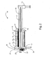
- motor reducers 22 stop, the liquid to be filtered is pumped in the pipe union 23, shown with reference to figure 2 , and in cushions 20 is inflayed compressed air (or another fluid) at medium pressure. This implies a second squashing force, greater than that previously due to the screws 19, taking up slack between filtering plates 14.
- the cushions 20 are deflated and at the same time screws 19 are moved, displacing further the movable plate 15 in order to take up slack originating from the settling due to the second squashing.
- the aim of this two squashing is that of taking up the slack between the filtering plates 14, the pressing plate 21, the fixed 12 and movable 15 plates, and to give the greatest possible first compression to filtering plates 14 and to allow for cushions 20, subsequently after their blowing, only the minimal expansion exclusively due to the remaining compression due to the resiliency of some materials.
- the subsequent step is the deflation of cushions 20 that, being cushions itself close to pneumatic or hydraulic apparatuses, also arranged on the fixed headpiece 12, or anyway close to it, will be very fast.
- the pressing plate 21 is unlocked and the screws 19 are started, spacing apart the plates 14 until they reach the position shown in figure 3 , allowing for the removal of permeate accumulated in the filtering plates 14 now open.
- a filter press is shown of the same kind of that shown with reference to figures 1 - 3 , but wherein cushions 20 and the pressing plate 21 are arranged before the fixed headpiece 12.
- a filter press is shown wherein approaching is obtained with an oleodynamic piston, but presenting an optimised solution of the compression step with respect to the solutions of the prior art, due to the fact that cushions, positioned on the side of the fixed headpiece 12 rather than on that of the movable headpiece 15, do nothave dimensional limitations due to the supporting frame of the filtering plates.
- a filter press 60 is shown with an upper rail 61.
- the supporting frame is constituted by the upper rail 61, supporting a plurality of filtering plates 64 arranged side by side between a fixed headpiece 62 and a movable headpiece 65, representing the backing plates.
- the movable headpiece 65 is in turn hanging at the upper rail 61 and it is provided on each corner 68 with a threaded cylindrical hole, engaged with an endless screw 69.
- the four endless screws 69 are rotated by corresponding motor reducers 72.
- the combined action filter press according to the present invention presents a series of advantages compared with the prior art, that will be explained with reference to the embodiment of figures 1 - 3 , but are also present in the embodiment of the subsequent figures.
- the combination of the action of cushions 20 and screws 19 allows for a very strong tightening of the filtering plates 14, squashing them to the headpiece 21.
- the subsequent advantage is a minimum opening of the cushions 20 during the inflation step, with a consequent increase of their resistance to explosion and greater working pressure, and a smaller time for inflation and hence higher productivity.
- the use of screw 19 makes the apparatus become expansible or ri-dimensionable, allowing for the possibility of adding or removing filtering plates 14 very quickly, depending on any possible working need and without any need for modifying the frame of the apparatus, and without the need for stopping the same.
- the combination of the action of compression exerted by cushions 20 and screws 19 is that of obtaining, in presence of variations of the thickness of the filtering plates 14 or even only of their cloths, when replacing them because of breakage or needs due to changes in the production process, a complete and automatic possibility to adapt even with changes of many centimetres.
- the position of cushions 20 on the fixed headpiece 12 be it external ( figures 1 - 3 ) or internal ( figure 4 ), but anyway close to the equipment for the inlet of the inflation fluid; implies a higher speed during the operation of inflation and deflation, with a decrease of working time.
- the position of cushions 20 and of the hydraulic, electric and pneumatic equipment on the fixed headpiece 12 allows for a better control and maintenance by an operator, since he can work completely safe, clear of the reach of any moving component, in particular when the cushions are positioned on the exterior of the fixed headpiece 12.
- Another advantage following to the displacement of the cushions 20 from the movable plate 15 to the fixed plate 12 and to the use of screws 19 for pressing is that of having the possibility to arrange the electric motor 22 and all the electric, hydraulic or pneumatic equipment far from the filtering plates and out of the area of unload of slurries, that, due to the features of this kind of apparatus is very dirty and not compatible with complex equipment.
- Another advantage, not less important, is to be added to those above, that is the possibility of using the preliminary approaching and tightening system obtained with the screws also in the most recent filter presses, wherein lateral rails are replaced by a single upper rail.
Landscapes
- Chemical & Material Sciences (AREA)
- Chemical Kinetics & Catalysis (AREA)
- Filtration Of Liquid (AREA)
- Presses And Accessory Devices Thereof (AREA)
- Press Drives And Press Lines (AREA)
- Filtering Materials (AREA)
- Lubrication Details And Ventilation Of Internal Combustion Engines (AREA)
- Fats And Perfumes (AREA)
- Oscillators With Electromechanical Resonators (AREA)
Claims (7)
- Filterpresse (10, 60) umfassend einen Stützrahmen, der aus mindestens einer in Längsrichtung verlaufenden Schiene oder Führung (11, 61) besteht, die an ihren gegenüberliegenden Enden gestützt ist durch ein festes Kopfstück (12, 62) an einer Seite und durch einen Fuß (13, 63) an der anderen Seite, ein bewegliches Kopfstück (15, 65), das von der mindestens einen Führung (11, 61) gestützt wird, einer Vielzahl von Filterplatten (14, 64), die Seite an Seite zwischen dem festen Kopfstück (12, 62) und dem beweglichen Kopfstück (15, 65) angeordnet sind, pneumatischen Elementen oder Kissen (20, 70) zum Pressen sowie einer Kompressionsplatte (21, 71), dadurch gekennzeichnet, dass das bewegliche Kopfstück (15, 65) mit Gewinden versehene zylindrische Bohrungen aufweist, die auf Endlosschrauben (19, 69) montiert sind, deren Enden drehbar auf Halterungen montiert sind, die mit den relativen Führungen (11, 61) einheitlich sind.
- Filterpresse (10, 60) gemäß Anspruch 1, dadurch gekennzeichnet, dass der Stützrahmen aus zwei seitlichen, in Längsrichtung verlaufenden Schienen oder Führungen (11) besteht, die an den gegenüberliegenden Enden durch ein festes Kopfstück (12) an einer Seite und durch einen Fuß (13) an der anderen Seite gehalten werden, ein bewegliches Kopfstück (15), das von der Führung (11) gestützt wird, eine Vielzahl von Filterplatten (14), die Seite an Seite zwischen dem festen Kopfstück (12) und dem beweglichen Kopfstück (15) angeordnet sind, pneumatischen Elementen oder Kissen (20) zum Pressen und einer Kompressionsplatte (21), wobei das bewegliche Kopfstück (15) zwei Arme (18) aufweist, einen für jede Seite, versehen mit jeweiligen, mit einem Gewinde versehenen zylindrischen Bohrungen, die von jeweiligen Endlosschrauben (19) gehalten werden, deren Enden drehbar auf Halterungen montiert sind, die mit dem Stützrahmen einheitlich sind.
- Filterpresse (10, 60) gemäß Anspruch 1, dadurch gekennzeichnet, dass der Stützrahmen besteht aus einer oberen, in Längsrichtung verlaufenden Schiene oder Führung (61), die an ihren gegenüberliegenden Enden durch ein festes Kopfstück (62) an einer Seite und durch einen Fuß (63) an der anderen Seite gehalten wird, ein bewegliches Kopfstück (65), das von der Führung (61) gehalten wird, eine Vielzahl von Filterplatten (64), die Seite an Seite zwischen dem festen Kopfstück (62) und dem beweglichen Kopfstück (65) angeordnet sind, pneumatischen Elementen oder Kissen (70) zum Pressen und einer Kompressionsplatte (71), wobei das bewegliche Kopfstück (65) an jeder Ecke mit einem Gewinde versehene zylindrische Bohrungen aufweist, die von jeweiligen Endlosschrauben (69) gehalten werden, deren Enden drehbar auf Halterungen montiert sind, die mit dem Stützrahmen einheitlich sind.
- Filterpresse (10, 60) gemäß einem der Ansprüche,
dadurch gekennzeichnet, dass die Endlosschrauben (19, 69) von einem Motor (22, 72) betrieben werden. - Filterpresse (10, 60) gemäß einem der Ansprüche,
dadurch gekennzeichnet, dass die Kissen (20, 70) und die Kompressionsplatte (21, 71) an dem festen Kopfstück (12, 72) angeordnet sind. - Filterpresse (10, 60) gemäß Anspruch 5, dadurch gekennzeichnet, dass die Kissen (20, 70) und die Kompressionsplatte (21, 71) an dem festen Kopfstück (12, 72) montiert werden können.
- Filterpresse (10, 60) gemäß Anspruch 5, dadurch gekennzeichnet, dass die Kissen (20, 70) und die Kompressionsplatte (21, 71) vor dem festen Kopfstück (12, 72) angeordnet sind.
Priority Applications (1)
| Application Number | Priority Date | Filing Date | Title |
|---|---|---|---|
| PL10711729T PL2396098T3 (pl) | 2009-02-10 | 2010-02-10 | Prasa filtracyjna o działaniu kombinowanym |
Applications Claiming Priority (2)
| Application Number | Priority Date | Filing Date | Title |
|---|---|---|---|
| IT000002A ITMS20090002A1 (it) | 2009-02-10 | 2009-02-10 | Filtropressa ad azione combinata |
| PCT/IT2010/000045 WO2010092612A1 (en) | 2009-02-10 | 2010-02-10 | Combined action filter press |
Publications (2)
| Publication Number | Publication Date |
|---|---|
| EP2396098A1 EP2396098A1 (de) | 2011-12-21 |
| EP2396098B1 true EP2396098B1 (de) | 2013-01-16 |
Family
ID=41066109
Family Applications (1)
| Application Number | Title | Priority Date | Filing Date |
|---|---|---|---|
| EP10711729A Not-in-force EP2396098B1 (de) | 2009-02-10 | 2010-02-10 | Filterpresse mit kombiniertem wirkungsmechanismus |
Country Status (21)
| Country | Link |
|---|---|
| US (1) | US8900450B2 (de) |
| EP (1) | EP2396098B1 (de) |
| JP (1) | JP5129395B2 (de) |
| CN (1) | CN102307637B (de) |
| AP (1) | AP2011005846A0 (de) |
| AU (1) | AU2010213388B2 (de) |
| BR (1) | BRPI1008329B1 (de) |
| CA (1) | CA2751847C (de) |
| CL (1) | CL2011001907A1 (de) |
| DK (1) | DK2396098T3 (de) |
| EA (1) | EA017761B1 (de) |
| EG (1) | EG26467A (de) |
| ES (1) | ES2403230T3 (de) |
| IT (1) | ITMS20090002A1 (de) |
| MX (1) | MX2011008380A (de) |
| NZ (1) | NZ594637A (de) |
| PE (1) | PE20120681A1 (de) |
| PL (1) | PL2396098T3 (de) |
| PT (1) | PT2396098E (de) |
| WO (1) | WO2010092612A1 (de) |
| ZA (1) | ZA201106000B (de) |
Families Citing this family (10)
| Publication number | Priority date | Publication date | Assignee | Title |
|---|---|---|---|---|
| WO2012148348A1 (en) * | 2011-04-27 | 2012-11-01 | Ge Healthcare Bio-Sciences Ab | Crossflow filtration cassette holder |
| DE202011050628U1 (de) * | 2011-07-04 | 2011-08-19 | Gölz GmbH | Filterpresse |
| RU2524968C2 (ru) * | 2013-02-19 | 2014-08-10 | Геннадий Леонидович Багич | Устройство очистки воды способом кристаллизации |
| RU2525494C2 (ru) * | 2013-02-19 | 2014-08-20 | Геннадий Леонидович Багич | Бытовое устройство приготовления легкой воды |
| FR3002866B1 (fr) | 2013-03-08 | 2018-02-02 | Noe Jacquier Energie | Dispositif et procede de desamiantage |
| EP3473319A1 (de) * | 2017-10-18 | 2019-04-24 | Metso Sweden Ab | Filterplattenanordnung und verfahren zum trennen der feststoffkomponenten von den flüssigen komponenten einer aufschlämmung |
| CN109020141A (zh) * | 2018-08-27 | 2018-12-18 | 深圳市纯水号水处理科技有限公司 | 一种海水淡化污泥处理用智能化压滤机 |
| MX2022007656A (es) * | 2019-12-20 | 2022-09-23 | Metso Outotec Finland Oy | Un filtro prensa y una placa de compresion de filtrado y kit de transporte de reequipamiento para un filtro prensa. |
| IT202000007498A1 (it) * | 2020-04-08 | 2021-10-08 | Italprogetti S P A | Filtropressa con testate fisse |
| CN111410397B (zh) * | 2020-04-27 | 2022-01-18 | 深圳华净环境科技有限公司 | 一种污泥处理装置 |
Family Cites Families (13)
| Publication number | Priority date | Publication date | Assignee | Title |
|---|---|---|---|---|
| US301795A (en) * | 1884-07-08 | Press | ||
| US749140A (en) * | 1904-01-05 | Filter-press | ||
| US2071891A (en) * | 1933-11-20 | 1937-02-23 | Meura Paul | Filter |
| JPS4328772Y1 (de) * | 1964-12-17 | 1968-11-26 | ||
| FI58723C (fi) | 1974-12-24 | 1981-04-10 | Ishigaki Mech Ind | Filterpress |
| JPS6024312U (ja) * | 1983-07-26 | 1985-02-19 | 株式会社クボタ | フイルタ−プレス |
| JPS6024311U (ja) * | 1983-07-26 | 1985-02-19 | 株式会社クボタ | フイルタ−プレス |
| JPH07124414A (ja) * | 1993-06-16 | 1995-05-16 | Kurita Mach Mfg Co Ltd | フィルタプレスの濾板締付装置 |
| JPH1043511A (ja) * | 1996-07-31 | 1998-02-17 | Miyamoto Riken Kogyo Kk | 脱水分離処理装置 |
| DE19904637C1 (de) * | 1999-02-05 | 2000-03-09 | Hoesch & Soehne Eberhard | Filterpresse zur Trennung von Suspensionen |
| CN1135133C (zh) | 2001-03-30 | 2004-01-21 | 朱兴源 | 高效能全自动压滤机及压滤方法 |
| US20080230461A1 (en) * | 2005-04-04 | 2008-09-25 | Horst Christian Schulte | Filter Press with Novel Filter Pack Clamping Arrangement |
| ITMS20070006A1 (it) * | 2007-03-19 | 2008-09-20 | Stefano Tongiani | Filtropressa idropneumatica |
-
2009
- 2009-02-10 IT IT000002A patent/ITMS20090002A1/it unknown
-
2010
- 2010-02-10 DK DK10711729.3T patent/DK2396098T3/da active
- 2010-02-10 CN CN201080007909.XA patent/CN102307637B/zh not_active Expired - Fee Related
- 2010-02-10 CA CA2751847A patent/CA2751847C/en not_active Expired - Fee Related
- 2010-02-10 EA EA201101198A patent/EA017761B1/ru not_active IP Right Cessation
- 2010-02-10 EP EP10711729A patent/EP2396098B1/de not_active Not-in-force
- 2010-02-10 ES ES10711729T patent/ES2403230T3/es active Active
- 2010-02-10 AU AU2010213388A patent/AU2010213388B2/en not_active Ceased
- 2010-02-10 WO PCT/IT2010/000045 patent/WO2010092612A1/en not_active Ceased
- 2010-02-10 PE PE2011001454A patent/PE20120681A1/es active IP Right Grant
- 2010-02-10 NZ NZ594637A patent/NZ594637A/xx not_active IP Right Cessation
- 2010-02-10 MX MX2011008380A patent/MX2011008380A/es active IP Right Grant
- 2010-02-10 JP JP2011548851A patent/JP5129395B2/ja not_active Expired - Fee Related
- 2010-02-10 AP AP2011005846A patent/AP2011005846A0/xx unknown
- 2010-02-10 PT PT107117293T patent/PT2396098E/pt unknown
- 2010-02-10 PL PL10711729T patent/PL2396098T3/pl unknown
- 2010-02-10 US US13/138,261 patent/US8900450B2/en not_active Expired - Fee Related
- 2010-02-10 BR BRPI1008329A patent/BRPI1008329B1/pt not_active IP Right Cessation
-
2011
- 2011-08-09 CL CL2011001907A patent/CL2011001907A1/es unknown
- 2011-08-09 EG EG2011081332A patent/EG26467A/en active
- 2011-08-16 ZA ZA2011/06000A patent/ZA201106000B/en unknown
Also Published As
| Publication number | Publication date |
|---|---|
| CN102307637A (zh) | 2012-01-04 |
| AU2010213388A1 (en) | 2011-09-08 |
| JP5129395B2 (ja) | 2013-01-30 |
| CA2751847C (en) | 2017-03-21 |
| US8900450B2 (en) | 2014-12-02 |
| CL2011001907A1 (es) | 2012-04-13 |
| PL2396098T3 (pl) | 2013-07-31 |
| NZ594637A (en) | 2013-10-25 |
| JP2012517335A (ja) | 2012-08-02 |
| BRPI1008329B1 (pt) | 2019-09-03 |
| BRPI1008329A2 (pt) | 2016-02-23 |
| CA2751847A1 (en) | 2010-08-19 |
| MX2011008380A (es) | 2011-11-01 |
| EP2396098A1 (de) | 2011-12-21 |
| DK2396098T3 (da) | 2013-04-22 |
| EA017761B1 (ru) | 2013-02-28 |
| PE20120681A1 (es) | 2012-06-15 |
| ZA201106000B (en) | 2012-10-31 |
| US20120048791A1 (en) | 2012-03-01 |
| ITMS20090002A1 (it) | 2010-08-11 |
| AP2011005846A0 (en) | 2011-08-31 |
| WO2010092612A1 (en) | 2010-08-19 |
| AU2010213388B2 (en) | 2014-10-02 |
| EG26467A (en) | 2013-11-14 |
| EA201101198A1 (ru) | 2012-01-30 |
| ES2403230T3 (es) | 2013-05-16 |
| PT2396098E (pt) | 2013-04-18 |
| CN102307637B (zh) | 2014-08-06 |
Similar Documents
| Publication | Publication Date | Title |
|---|---|---|
| CA2751847C (en) | Combined action filter press | |
| AU2019252265B2 (en) | Discharge filter plate assembly for filter press | |
| US20180346363A1 (en) | Electromagnetic-force-based dewatering for sewage sludge reduction | |
| CN102225260A (zh) | 一种自动压滤脱水设备及其工作方法 | |
| CN210097031U (zh) | 一种紧凑型高效压滤机 | |
| CA2603954C (en) | Filter press with novel filter pack clamping arrangement | |
| CN102225259A (zh) | 一种卧式自动压滤脱水设备及其工作方法 | |
| CN107008041B (zh) | 基于电磁力的污水污泥减量化脱水方法 | |
| US20090090256A1 (en) | Sludge Dewatering System | |
| CN203777738U (zh) | 压滤机 | |
| CN119926005A (zh) | 一种三级挤压式煤泥压滤设备与工作方法 | |
| CN104190125A (zh) | 高压压榨液压压紧机械螺旋锁紧压滤机 | |
| CN216366787U (zh) | 压力过滤器 | |
| CN116850658A (zh) | 一种滤板刮料机构及压滤机 | |
| CN104138677B (zh) | 一种圆盘式压滤装置及压滤方法 | |
| CN212236133U (zh) | 一种油缸底置压滤机 | |
| CN211987273U (zh) | 三次快开卸料式压滤机 | |
| CN217107628U (zh) | 一种压滤机液压系统及其压滤机 | |
| CN120679232B (zh) | 一种密封形式的卧式大通量过滤器 | |
| CN223144219U (zh) | 一种三元前驱体压滤设备用压滤机构 | |
| CN217724723U (zh) | 一种滤网拆卸方便的工业油脂过滤机 | |
| CN112479536A (zh) | 利用热泵与蒸汽压缩机功能的压滤干燥设备 | |
| CN215995747U (zh) | 一种密封性能良好的压滤机 | |
| WO2003057344A1 (en) | Method and apparatus for controlling the forming of a cake in a filter press | |
| EP0171649B1 (de) | Plattenfilter mit geringen Profilen |
Legal Events
| Date | Code | Title | Description |
|---|---|---|---|
| PUAI | Public reference made under article 153(3) epc to a published international application that has entered the european phase |
Free format text: ORIGINAL CODE: 0009012 |
|
| 17P | Request for examination filed |
Effective date: 20110810 |
|
| AK | Designated contracting states |
Kind code of ref document: A1 Designated state(s): AT BE BG CH CY CZ DE DK EE ES FI FR GB GR HR HU IE IS IT LI LT LU LV MC MK MT NL NO PL PT RO SE SI SK SM TR |
|
| DAX | Request for extension of the european patent (deleted) | ||
| REG | Reference to a national code |
Ref country code: DE Ref legal event code: R079 Ref document number: 602010004697 Country of ref document: DE Free format text: PREVIOUS MAIN CLASS: B01D0025120000 Ipc: B01D0025190000 |
|
| RIC1 | Information provided on ipc code assigned before grant |
Ipc: B01D 25/19 20060101AFI20120619BHEP Ipc: C02F 11/12 20060101ALI20120619BHEP Ipc: B01D 25/164 20060101ALI20120619BHEP |
|
| GRAP | Despatch of communication of intention to grant a patent |
Free format text: ORIGINAL CODE: EPIDOSNIGR1 |
|
| GRAS | Grant fee paid |
Free format text: ORIGINAL CODE: EPIDOSNIGR3 |
|
| GRAA | (expected) grant |
Free format text: ORIGINAL CODE: 0009210 |
|
| AK | Designated contracting states |
Kind code of ref document: B1 Designated state(s): AT BE BG CH CY CZ DE DK EE ES FI FR GB GR HR HU IE IS IT LI LT LU LV MC MK MT NL NO PL PT RO SE SI SK SM TR |
|
| REG | Reference to a national code |
Ref country code: GB Ref legal event code: FG4D |
|
| REG | Reference to a national code |
Ref country code: CH Ref legal event code: EP |
|
| REG | Reference to a national code |
Ref country code: IE Ref legal event code: FG4D |
|
| REG | Reference to a national code |
Ref country code: AT Ref legal event code: REF Ref document number: 593553 Country of ref document: AT Kind code of ref document: T Effective date: 20130215 Ref country code: CH Ref legal event code: EP |
|
| REG | Reference to a national code |
Ref country code: DE Ref legal event code: R096 Ref document number: 602010004697 Country of ref document: DE Effective date: 20130314 |
|
| REG | Reference to a national code |
Ref country code: RO Ref legal event code: EPE |
|
| REG | Reference to a national code |
Ref country code: PT Ref legal event code: SC4A Free format text: AVAILABILITY OF NATIONAL TRANSLATION Effective date: 20130412 |
|
| REG | Reference to a national code |
Ref country code: DK Ref legal event code: T3 |
|
| REG | Reference to a national code |
Ref country code: PT Ref legal event code: PC4A Owner name: TENOVA S.P.A., IT Effective date: 20130418 |
|
| RAP2 | Party data changed (patent owner data changed or rights of a patent transferred) |
Owner name: TONGIANI, STEFANO |
|
| RIN2 | Information on inventor provided after grant (corrected) |
Inventor name: TONGIANI, STEFANO |
|
| REG | Reference to a national code |
Ref country code: SE Ref legal event code: TRGR |
|
| RAP2 | Party data changed (patent owner data changed or rights of a patent transferred) |
Owner name: TENOVA S.P.A. |
|
| RIN2 | Information on inventor provided after grant (corrected) |
Inventor name: TENOVA S.P.A. |
|
| REG | Reference to a national code |
Ref country code: ES Ref legal event code: FG2A Ref document number: 2403230 Country of ref document: ES Kind code of ref document: T3 Effective date: 20130516 |
|
| REG | Reference to a national code |
Ref country code: NO Ref legal event code: T2 Effective date: 20130116 |
|
| REG | Reference to a national code |
Ref country code: NL Ref legal event code: SD Effective date: 20130606 Ref country code: NL Ref legal event code: T3 Ref country code: DE Ref legal event code: R082 Ref document number: 602010004697 Country of ref document: DE Representative=s name: WUESTHOFF & WUESTHOFF PATENT- UND RECHTSANWAEL, DE |
|
| REG | Reference to a national code |
Ref country code: GR Ref legal event code: EP Ref document number: 20130400762 Country of ref document: GR Effective date: 20130517 |
|
| REG | Reference to a national code |
Ref country code: LT Ref legal event code: MG4D |
|
| PG25 | Lapsed in a contracting state [announced via postgrant information from national office to epo] |
Ref country code: LT Free format text: LAPSE BECAUSE OF FAILURE TO SUBMIT A TRANSLATION OF THE DESCRIPTION OR TO PAY THE FEE WITHIN THE PRESCRIBED TIME-LIMIT Effective date: 20130116 Ref country code: IS Free format text: LAPSE BECAUSE OF FAILURE TO SUBMIT A TRANSLATION OF THE DESCRIPTION OR TO PAY THE FEE WITHIN THE PRESCRIBED TIME-LIMIT Effective date: 20130516 |
|
| REG | Reference to a national code |
Ref country code: PL Ref legal event code: T3 |
|
| REG | Reference to a national code |
Ref country code: DE Ref legal event code: R082 Ref document number: 602010004697 Country of ref document: DE Representative=s name: WUESTHOFF & WUESTHOFF, PATENTANWAELTE PARTG MB, DE Effective date: 20130612 Ref country code: DE Ref legal event code: R081 Ref document number: 602010004697 Country of ref document: DE Owner name: TENOVA S.P.A., IT Free format text: FORMER OWNER: TONGIANI, STEFANO, MASSA, IT Effective date: 20130612 Ref country code: DE Ref legal event code: R082 Ref document number: 602010004697 Country of ref document: DE Representative=s name: WUESTHOFF & WUESTHOFF PATENT- UND RECHTSANWAEL, DE Effective date: 20130612 |
|
| REG | Reference to a national code |
Ref country code: EE Ref legal event code: FG4A Ref document number: E007997 Country of ref document: EE Effective date: 20130416 |
|
| PG25 | Lapsed in a contracting state [announced via postgrant information from national office to epo] |
Ref country code: SI Free format text: LAPSE BECAUSE OF FAILURE TO SUBMIT A TRANSLATION OF THE DESCRIPTION OR TO PAY THE FEE WITHIN THE PRESCRIBED TIME-LIMIT Effective date: 20130116 Ref country code: LV Free format text: LAPSE BECAUSE OF FAILURE TO SUBMIT A TRANSLATION OF THE DESCRIPTION OR TO PAY THE FEE WITHIN THE PRESCRIBED TIME-LIMIT Effective date: 20130116 |
|
| REG | Reference to a national code |
Ref country code: SK Ref legal event code: T3 Ref document number: E 14319 Country of ref document: SK |
|
| PG25 | Lapsed in a contracting state [announced via postgrant information from national office to epo] |
Ref country code: MC Free format text: LAPSE BECAUSE OF NON-PAYMENT OF DUE FEES Effective date: 20130228 Ref country code: HR Free format text: LAPSE BECAUSE OF FAILURE TO SUBMIT A TRANSLATION OF THE DESCRIPTION OR TO PAY THE FEE WITHIN THE PRESCRIBED TIME-LIMIT Effective date: 20130116 |
|
| PLBE | No opposition filed within time limit |
Free format text: ORIGINAL CODE: 0009261 |
|
| STAA | Information on the status of an ep patent application or granted ep patent |
Free format text: STATUS: NO OPPOSITION FILED WITHIN TIME LIMIT |
|
| PG25 | Lapsed in a contracting state [announced via postgrant information from national office to epo] |
Ref country code: CY Free format text: LAPSE BECAUSE OF FAILURE TO SUBMIT A TRANSLATION OF THE DESCRIPTION OR TO PAY THE FEE WITHIN THE PRESCRIBED TIME-LIMIT Effective date: 20130116 |
|
| 26N | No opposition filed |
Effective date: 20131017 |
|
| REG | Reference to a national code |
Ref country code: DE Ref legal event code: R097 Ref document number: 602010004697 Country of ref document: DE Effective date: 20131017 |
|
| PG25 | Lapsed in a contracting state [announced via postgrant information from national office to epo] |
Ref country code: MT Free format text: LAPSE BECAUSE OF FAILURE TO SUBMIT A TRANSLATION OF THE DESCRIPTION OR TO PAY THE FEE WITHIN THE PRESCRIBED TIME-LIMIT Effective date: 20130116 |
|
| REG | Reference to a national code |
Ref country code: CH Ref legal event code: PL |
|
| PG25 | Lapsed in a contracting state [announced via postgrant information from national office to epo] |
Ref country code: LI Free format text: LAPSE BECAUSE OF NON-PAYMENT OF DUE FEES Effective date: 20140228 Ref country code: CH Free format text: LAPSE BECAUSE OF NON-PAYMENT OF DUE FEES Effective date: 20140228 |
|
| PG25 | Lapsed in a contracting state [announced via postgrant information from national office to epo] |
Ref country code: SM Free format text: LAPSE BECAUSE OF FAILURE TO SUBMIT A TRANSLATION OF THE DESCRIPTION OR TO PAY THE FEE WITHIN THE PRESCRIBED TIME-LIMIT Effective date: 20130116 |
|
| PG25 | Lapsed in a contracting state [announced via postgrant information from national office to epo] |
Ref country code: HU Free format text: LAPSE BECAUSE OF FAILURE TO SUBMIT A TRANSLATION OF THE DESCRIPTION OR TO PAY THE FEE WITHIN THE PRESCRIBED TIME-LIMIT; INVALID AB INITIO Effective date: 20100210 Ref country code: LU Free format text: LAPSE BECAUSE OF NON-PAYMENT OF DUE FEES Effective date: 20130210 Ref country code: MK Free format text: LAPSE BECAUSE OF FAILURE TO SUBMIT A TRANSLATION OF THE DESCRIPTION OR TO PAY THE FEE WITHIN THE PRESCRIBED TIME-LIMIT Effective date: 20130116 |
|
| REG | Reference to a national code |
Ref country code: FR Ref legal event code: PLFP Year of fee payment: 7 |
|
| PGFP | Annual fee paid to national office [announced via postgrant information from national office to epo] |
Ref country code: SK Payment date: 20160206 Year of fee payment: 7 Ref country code: EE Payment date: 20160125 Year of fee payment: 7 Ref country code: DK Payment date: 20160210 Year of fee payment: 7 Ref country code: CZ Payment date: 20160204 Year of fee payment: 7 Ref country code: IE Payment date: 20160209 Year of fee payment: 7 Ref country code: BG Payment date: 20160229 Year of fee payment: 7 Ref country code: NO Payment date: 20160209 Year of fee payment: 7 |
|
| PGFP | Annual fee paid to national office [announced via postgrant information from national office to epo] |
Ref country code: PL Payment date: 20160127 Year of fee payment: 7 Ref country code: NL Payment date: 20160210 Year of fee payment: 7 Ref country code: GR Payment date: 20160201 Year of fee payment: 7 Ref country code: RO Payment date: 20160205 Year of fee payment: 7 Ref country code: PT Payment date: 20160204 Year of fee payment: 7 |
|
| REG | Reference to a national code |
Ref country code: FR Ref legal event code: PLFP Year of fee payment: 8 |
|
| REG | Reference to a national code |
Ref country code: EE Ref legal event code: MM4A Ref document number: E007997 Country of ref document: EE Effective date: 20170228 |
|
| REG | Reference to a national code |
Ref country code: DK Ref legal event code: EBP Effective date: 20170228 |
|
| REG | Reference to a national code |
Ref country code: NO Ref legal event code: MMEP |
|
| REG | Reference to a national code |
Ref country code: NL Ref legal event code: MM Effective date: 20170301 |
|
| PG25 | Lapsed in a contracting state [announced via postgrant information from national office to epo] |
Ref country code: RO Free format text: LAPSE BECAUSE OF NON-PAYMENT OF DUE FEES Effective date: 20170210 Ref country code: NO Free format text: LAPSE BECAUSE OF NON-PAYMENT OF DUE FEES Effective date: 20170228 Ref country code: GR Free format text: LAPSE BECAUSE OF NON-PAYMENT OF DUE FEES Effective date: 20170906 Ref country code: CZ Free format text: LAPSE BECAUSE OF NON-PAYMENT OF DUE FEES Effective date: 20170210 Ref country code: SK Free format text: LAPSE BECAUSE OF NON-PAYMENT OF DUE FEES Effective date: 20170210 Ref country code: EE Free format text: LAPSE BECAUSE OF NON-PAYMENT OF DUE FEES Effective date: 20170228 |
|
| REG | Reference to a national code |
Ref country code: SK Ref legal event code: MM4A Ref document number: E 14319 Country of ref document: SK Effective date: 20170210 |
|
| REG | Reference to a national code |
Ref country code: IE Ref legal event code: MM4A |
|
| PG25 | Lapsed in a contracting state [announced via postgrant information from national office to epo] |
Ref country code: NL Free format text: LAPSE BECAUSE OF NON-PAYMENT OF DUE FEES Effective date: 20170301 Ref country code: PT Free format text: LAPSE BECAUSE OF NON-PAYMENT OF DUE FEES Effective date: 20170810 |
|
| PG25 | Lapsed in a contracting state [announced via postgrant information from national office to epo] |
Ref country code: DK Free format text: LAPSE BECAUSE OF NON-PAYMENT OF DUE FEES Effective date: 20170228 |
|
| REG | Reference to a national code |
Ref country code: FR Ref legal event code: PLFP Year of fee payment: 9 |
|
| PG25 | Lapsed in a contracting state [announced via postgrant information from national office to epo] |
Ref country code: IE Free format text: LAPSE BECAUSE OF NON-PAYMENT OF DUE FEES Effective date: 20170210 |
|
| PGFP | Annual fee paid to national office [announced via postgrant information from national office to epo] |
Ref country code: GB Payment date: 20180227 Year of fee payment: 9 |
|
| PGFP | Annual fee paid to national office [announced via postgrant information from national office to epo] |
Ref country code: BE Payment date: 20180227 Year of fee payment: 9 Ref country code: FR Payment date: 20180227 Year of fee payment: 9 |
|
| PG25 | Lapsed in a contracting state [announced via postgrant information from national office to epo] |
Ref country code: PL Free format text: LAPSE BECAUSE OF NON-PAYMENT OF DUE FEES Effective date: 20170210 |
|
| PG25 | Lapsed in a contracting state [announced via postgrant information from national office to epo] |
Ref country code: BG Free format text: LAPSE BECAUSE OF NON-PAYMENT OF DUE FEES Effective date: 20170903 |
|
| GBPC | Gb: european patent ceased through non-payment of renewal fee |
Effective date: 20190210 |
|
| REG | Reference to a national code |
Ref country code: BE Ref legal event code: MM Effective date: 20190228 |
|
| PG25 | Lapsed in a contracting state [announced via postgrant information from national office to epo] |
Ref country code: GB Free format text: LAPSE BECAUSE OF NON-PAYMENT OF DUE FEES Effective date: 20190210 |
|
| PG25 | Lapsed in a contracting state [announced via postgrant information from national office to epo] |
Ref country code: FR Free format text: LAPSE BECAUSE OF NON-PAYMENT OF DUE FEES Effective date: 20190228 Ref country code: BE Free format text: LAPSE BECAUSE OF NON-PAYMENT OF DUE FEES Effective date: 20190228 |
|
| PGFP | Annual fee paid to national office [announced via postgrant information from national office to epo] |
Ref country code: IT Payment date: 20210219 Year of fee payment: 12 Ref country code: FI Payment date: 20210225 Year of fee payment: 12 |
|
| PGFP | Annual fee paid to national office [announced via postgrant information from national office to epo] |
Ref country code: DE Payment date: 20210225 Year of fee payment: 12 Ref country code: ES Payment date: 20210301 Year of fee payment: 12 Ref country code: AT Payment date: 20210120 Year of fee payment: 12 Ref country code: SE Payment date: 20210225 Year of fee payment: 12 Ref country code: TR Payment date: 20210128 Year of fee payment: 12 |
|
| REG | Reference to a national code |
Ref country code: DE Ref legal event code: R119 Ref document number: 602010004697 Country of ref document: DE |
|
| REG | Reference to a national code |
Ref country code: FI Ref legal event code: MAE |
|
| REG | Reference to a national code |
Ref country code: SE Ref legal event code: EUG |
|
| REG | Reference to a national code |
Ref country code: AT Ref legal event code: MM01 Ref document number: 593553 Country of ref document: AT Kind code of ref document: T Effective date: 20220210 |
|
| PG25 | Lapsed in a contracting state [announced via postgrant information from national office to epo] |
Ref country code: SE Free format text: LAPSE BECAUSE OF NON-PAYMENT OF DUE FEES Effective date: 20220211 Ref country code: FI Free format text: LAPSE BECAUSE OF NON-PAYMENT OF DUE FEES Effective date: 20220210 Ref country code: AT Free format text: LAPSE BECAUSE OF NON-PAYMENT OF DUE FEES Effective date: 20220210 |
|
| PG25 | Lapsed in a contracting state [announced via postgrant information from national office to epo] |
Ref country code: DE Free format text: LAPSE BECAUSE OF NON-PAYMENT OF DUE FEES Effective date: 20220901 |
|
| REG | Reference to a national code |
Ref country code: ES Ref legal event code: FD2A Effective date: 20230428 |
|
| PG25 | Lapsed in a contracting state [announced via postgrant information from national office to epo] |
Ref country code: IT Free format text: LAPSE BECAUSE OF NON-PAYMENT OF DUE FEES Effective date: 20220210 |
|
| PG25 | Lapsed in a contracting state [announced via postgrant information from national office to epo] |
Ref country code: ES Free format text: LAPSE BECAUSE OF NON-PAYMENT OF DUE FEES Effective date: 20220211 |
|
| PG25 | Lapsed in a contracting state [announced via postgrant information from national office to epo] |
Ref country code: TR Free format text: LAPSE BECAUSE OF NON-PAYMENT OF DUE FEES Effective date: 20220210 |