EP2394879B1 - Dispositif de basculement d'une porte d'étrave et module de porte d'étrave - Google Patents
Dispositif de basculement d'une porte d'étrave et module de porte d'étrave Download PDFInfo
- Publication number
- EP2394879B1 EP2394879B1 EP10165279.0A EP10165279A EP2394879B1 EP 2394879 B1 EP2394879 B1 EP 2394879B1 EP 10165279 A EP10165279 A EP 10165279A EP 2394879 B1 EP2394879 B1 EP 2394879B1
- Authority
- EP
- European Patent Office
- Prior art keywords
- actuating
- pivot lever
- actuating mechanism
- rod
- pivot
- Prior art date
- Legal status (The legal status is an assumption and is not a legal conclusion. Google has not performed a legal analysis and makes no representation as to the accuracy of the status listed.)
- Not-in-force
Links
- 125000006850 spacer group Chemical group 0.000 claims description 12
- 239000011152 fibreglass Substances 0.000 claims description 2
- 101001017827 Mus musculus Leucine-rich repeat flightless-interacting protein 1 Proteins 0.000 description 4
- 238000000418 atomic force spectrum Methods 0.000 description 2
- 230000006835 compression Effects 0.000 description 2
- 238000007906 compression Methods 0.000 description 2
- 230000008878 coupling Effects 0.000 description 2
- 238000010168 coupling process Methods 0.000 description 2
- 238000005859 coupling reaction Methods 0.000 description 2
- 230000001360 synchronised effect Effects 0.000 description 2
- 230000000712 assembly Effects 0.000 description 1
- 238000000429 assembly Methods 0.000 description 1
- 230000001419 dependent effect Effects 0.000 description 1
- 238000011161 development Methods 0.000 description 1
- 230000018109 developmental process Effects 0.000 description 1
- 238000005516 engineering process Methods 0.000 description 1
- 230000007613 environmental effect Effects 0.000 description 1
- 239000011521 glass Substances 0.000 description 1
- 230000003993 interaction Effects 0.000 description 1
Images




Classifications
-
- B—PERFORMING OPERATIONS; TRANSPORTING
- B61—RAILWAYS
- B61F—RAIL VEHICLE SUSPENSIONS, e.g. UNDERFRAMES, BOGIES OR ARRANGEMENTS OF WHEEL AXLES; RAIL VEHICLES FOR USE ON TRACKS OF DIFFERENT WIDTH; PREVENTING DERAILING OF RAIL VEHICLES; WHEEL GUARDS, OBSTRUCTION REMOVERS OR THE LIKE FOR RAIL VEHICLES
- B61F19/00—Wheel guards; Bumpers; Obstruction removers or the like
- B61F19/04—Bumpers or like collision guards
-
- B—PERFORMING OPERATIONS; TRANSPORTING
- B61—RAILWAYS
- B61D—BODY DETAILS OR KINDS OF RAILWAY VEHICLES
- B61D15/00—Other railway vehicles, e.g. scaffold cars; Adaptations of vehicles for use on railways
- B61D15/06—Buffer cars; Arrangements or construction of railway vehicles for protecting them in case of collisions
-
- B—PERFORMING OPERATIONS; TRANSPORTING
- B61—RAILWAYS
- B61D—BODY DETAILS OR KINDS OF RAILWAY VEHICLES
- B61D17/00—Construction details of vehicle bodies
- B61D17/04—Construction details of vehicle bodies with bodies of metal; with composite, e.g. metal and wood body structures
- B61D17/06—End walls
-
- B—PERFORMING OPERATIONS; TRANSPORTING
- B61—RAILWAYS
- B61F—RAIL VEHICLE SUSPENSIONS, e.g. UNDERFRAMES, BOGIES OR ARRANGEMENTS OF WHEEL AXLES; RAIL VEHICLES FOR USE ON TRACKS OF DIFFERENT WIDTH; PREVENTING DERAILING OF RAIL VEHICLES; WHEEL GUARDS, OBSTRUCTION REMOVERS OR THE LIKE FOR RAIL VEHICLES
- B61F19/00—Wheel guards; Bumpers; Obstruction removers or the like
- B61F19/02—Wheel guards
Definitions
- the invention relates to a device for pivoting a nose flap of a track-guided vehicle, in particular rail vehicle, and a BugklappenModul.
- a device for pivoting a nose flap of a track-guided vehicle, in particular rail vehicle, and a BugklappenModul is, for example by the EP 1 857 340 A2 known.
- a bow flap which cover the coupling shaft in the closed state to protect components or components of the clutch assembly against environmental influences, such as dirt, ice or icing.
- a nose flap may have the function of avoiding aerodynamically disadvantageous front parts, which is particularly important in streamlined multiple units, such as high-speed trains, of importance.
- the present invention has for its object to provide a nose flap kinematics, which has a simple structure and is characterized by its reliability.
- a device for pivoting a bow door a track-guided vehicle and a Bugklappenmodul be given, with which due to the simple structure weight can be saved, while the susceptibility is reduced.
- a device for pivoting a nose flap is specified, as described in claim 1.
- the two actuating elements are each designed in the form of a preferably pneumatically, hydraulically or electrically operating actuating cylinder, which has a retractable and retractable piston rod.
- This piston rod preferably cooperates via an actuating mechanism with the associated pivoting lever.
- the actuating mechanism on the one hand has a lever and on the other hand an eccentric.
- the piston rod of the associated actuating element should be articulated on the reversing lever.
- the eccentric disc of the actuating mechanism should be connected to an end portion of the rod-shaped synchronization element.
- the lever interact with the eccentric disc such that upon actuation of the corresponding actuating element, the torque acting on the lever at least partially transmitted to the eccentric disc and from there to the rod-shaped synchronization element becomes.
- the reversing lever of the actuating mechanism is preferably on the one hand vertically to the direction of travel of the vehicle pivotally connected to the vehicle undercarriage (vehicle frame) and on the other hand connected via the eccentric disc with the synchronization element.
- the term "bellcrank” as used herein basically means a mechanism which is designed to convert a translational movement into a rotational movement of the eccentric disc.
- the unlatching lever of each actuating mechanism is relative to the vehicle undercarriage about an axis of rotation extending parallel to the rod-shaped synchronization element rotatable.
- the eccentric disk of each actuating mechanism should preferably be rotatable relative to the vehicle undercarriage about the rotation axis common to the two pivoting levers.
- the actuating elements are respectively pivotable relative to the vehicle undercarriage about an axis parallel to the rod-shaped synchronization element axis of rotation, wherein the bell crank of each actuating mechanism relative to the vehicle undercarriage should be rotatable about a parallel to the rod-shaped synchronization element rotation axis and a slotted guide for forcedly guiding the eccentric disc the actuating mechanism.
- a slotted guide By providing such a slotted guide, the linear movement exerted with the actuating element linear movement can be converted into a rotational movement, which is needed for pivoting the nose flap relative to the vehicle undercarriage in an easy to implement manner.
- the actuating mechanism has a connecting rod, which is articulated on the one hand to the reversing lever of the actuating mechanism and on the other hand on the eccentric disc of the actuating mechanism.
- each actuator is arranged with the associated actuating mechanism between two firmly connectable to the vehicle underframe carrier plates to protect the sensitive assemblies of the front door kinematics.
- the carrier plates are each in a plane perpendicular to the orientation of the rod-shaped synchronization element and are firmly connected to each other via at least one spacer element.
- each actuating mechanism may comprise a compression spring, in particular a gas pressure spring, which on the one hand on the Eccentric disc of the actuating mechanism and on the other hand hinged to a second of the at least two spacer elements.
- a stop is provided on at least one of the two carrier plates.
- the first and second pivot levers are pivotally connected in each case about an axis parallel to the rod-shaped synchronization element axis of rotation with the nose flap.
- at least a first and a second additional pivot lever should be provided, which cooperate with the first and second pivot lever such that the first pivot lever with the first additional pivot lever and the second pivot lever with the second additional pivot lever each form a four-joint , via which the nose flap can be connected to the vehicle undercarriage.
- a frame frame which is preferably detachably fastened to the vehicle underframe, via which the first and the second actuating element are connected (indirectly) to the vehicle undercarriage.
- the invention further relates to a bulkhead module for a track-guided vehicle, in particular rail vehicle, wherein the Bugklappenmodul has a preferably made of a fiberglass reinforced plastic nose flap and a Bugklappen kinematics with a device of the type described above for pivoting the nose flap.
- Bugklappenmoduls 100 is described with reference to the accompanying drawings, in which for pivoting a nose flap 1, a device (Bugklappen kinematics) according to the present invention is used.
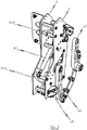
- Fig. 1 the illustrated embodiment of the solution according to the invention on a single bow door 1, which can be pivoted by means of two lateral drive units relative to a (not shown) vehicle undercarriage to release the work area of a coverable from the bow door 1 clutch.
- the lateral drive units which are used in the exemplary embodiment of the Bugklappenmoduls invention 100 and overall justify the Bugklappen kinematics, are symmetrical to each other to ensure a torque-free force curve in the drive train.
- each of the two lateral drive units has an actuating element 14, 14 'and an actuating mechanism assigned to the corresponding actuating element 14, 14'.
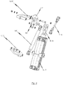
- FIG Fig. 2 referenced, in which the individual components of one of the two drive units are shown together with the bow door 1.
- each drive unit has an actuating element 14, 14 ', which in the illustrated exemplary embodiment, a pneumatically, hydraulically or electrically operating actuating cylinder 15, 15' and on actuation of the actuating element 14, 14 'from the actuating cylinder 15, 15' off or .
- retractable piston rod 16, 16 ' has.
- an actuating mechanism is provided, with which the force acting on the piston rod 16, 16' of the actuating element 14, 14 'linear force is converted into a rotational movement to pivot the bow door 1 relative to the vehicle undercarriage on a corresponding lever mechanism Apply torque.
- the pivoting mechanism has a first with the bow flap 1 releasably connected pivot lever 3 and a second with the bow flap 1 releasably connected pivot lever 3 ', wherein the first pivot lever 3 with the first actuator 14 of the first drive unit and the second pivot lever 3' cooperates with the second actuating element 14 'of the second drive unit.
- each drive unit has an actuating mechanism which connects the corresponding actuating element 14, 14 'with the associated pivot lever 3, 3'.
- the actuating mechanism has in the exemplary embodiment, a lever 7, 7 ', on which the piston rod 16, 16' of the actuating element 14, 14 'is articulated.
- an eccentric disc 8, 8 ' is provided, which cooperates with the reversing lever 7, 7' in such a manner that upon actuation of the corresponding actuating element 14, 14 ', the torque acting on the reversing lever 7, 7' is at least partially applied to the eccentric disc 8, 8 '. is transmitted.
- the solution according to the invention is characterized not only by the fact that for pivoting the bow door 1, two separate drive units consisting of an actuating element 14, 14 'and an associated actuating mechanism for Are used, but in particular also by the fact that a synchronization element 10 is provided, with which with the aid of the individual actuating elements 14, 14 'on the associated pivot lever 3, 3' applied rotational movement can be synchronized.
- a synchronization element 10 is provided, with which with the aid of the individual actuating elements 14, 14 'on the associated pivot lever 3, 3' applied rotational movement can be synchronized.
- a rod-shaped element is used, which lies on the common axis of rotation R of the two pivot levers 3, 3 '. It is provided that the rod-shaped synchronization element 10 is connected on the one hand to the first pivot lever 3 and on the other hand to the second pivot lever 3 '.
- the respective end portions of the rod-shaped synchronization element 10 are connected to the eccentric disc 8 belonging to the first actuator 14 actuating mechanism and with the eccentric 8 'of the second actuator 14' associated actuating mechanism, so that upon actuation of at least one of the actuators 14, 14 'on the associated deflection lever 7, 7 'acting torque is transmitted to the associated eccentric disc 8, 8' and from there to the rod-shaped synchronization element 10.
- each actuating mechanism is rotatable relative to the vehicle undercarriage about an axis parallel to the rod-shaped synchronization element 10 axis of rotation, wherein the eccentric disc 8, 8' of each Actuating mechanism relative to the vehicle undercarriage about the two pivot lever 3, 3 'common rotation axis R is rotatable.
- each actuating mechanism is rotatable relative to the vehicle undercarriage about an axis parallel to the rod-shaped synchronization element 10 extending axis of rotation and has a slotted guide to forcibly guide the actuating mechanism associated eccentric 8, 8'.
- Each actuating mechanism further comprises a connecting rod 11, 11 ', which is hinged on the one hand to the deflection lever 7, 7' of the actuating mechanism and on the other hand on the eccentric disc 8, 8 'of the actuating mechanism.
- the actuating elements 14, 14 'with the associated actuating mechanism between two firmly fixed to the vehicle underframe carrier plates 5, 5' are arranged.
- each actuating mechanism is rotatably connected to a parallel to the rod-shaped synchronization element 10 axis of rotation with a first spacer element 12, 12'.
- each actuating mechanism further comprises a compression spring 9, 9 ', in particular a gas spring, which is articulated on the one hand to the eccentric disc 8, 8' of the actuating mechanism and on the other hand to a second spacer element 13, 13 '.
- Each actuating element 14, 14 ' is rotatably connected to the two associated carrier plates 5, 5' about a rotation axis running parallel to the rod-shaped synchronization element 10.
- first and second pivot levers 3, 3 ' are each pivotally connected to the bow flap 1 about a rotation axis parallel to the rod-shaped synchronization element 10.
- a frame frame which is preferably detachably fastened to the vehicle underframe is provided, wherein the first and second actuating element 14, 14 'are connected to this frame frame.
- the invention is characterized in that for pivoting the bow door 1, two symmetrically constructed drive units are used, each of the two drive units having an actuating element 14, 14 'and an actuating mechanism to a torque on the actuation of the actuating element 14, 14' associated pivot lever 3, 3 'exercise.
- the pivoting levers 3, 3 'of the two drive units are coupled to one another via the rod-shaped synchronization element 10, so that both drive units are redundant. Even with failure of one of the two drive units, a drive unit is sufficient to fulfill the function and to enable a pivoting of the bow door 1 relative to the vehicle undercarriage. It is essential that both drive units are constructed of identical components, whereby these drive units are symmetrical and can be realized inexpensively. Due to the symmetrical design of the drive units a torque-free force curve in the drive train is guaranteed.
Landscapes
- Engineering & Computer Science (AREA)
- Mechanical Engineering (AREA)
- Life Sciences & Earth Sciences (AREA)
- Wood Science & Technology (AREA)
- Transportation (AREA)
- Actuator (AREA)
- Power-Operated Mechanisms For Wings (AREA)
- Vehicle Body Suspensions (AREA)
- Transmission Devices (AREA)
Claims (12)
- Dispositif pour faire basculer un capot d'étrave (1) d'un véhicule guidé sur voie, en particulier un véhicule ferroviaire, dans lequel le dispositif est réalisé pour faire basculer le capot d'étrave (1) par rapport à un châssis inférieur du véhicule guidé sur voie, avec un mouvement qui est une superposition d'un mouvement linéaire et d'un mouvement de basculement, dans lequel le dispositif comprend les éléments suivants :- un premier levier basculant (3) à relier avec le capot d'étrave (1) et un second levier basculant (3') à relier avec le capot d'étrave (1), dans lequel, pour faire basculer le capot d'étrave (1) par rapport au châssis inférieur du véhicule, les deux leviers basculants (3, 3') sont capables de rotation autour d'un axe de rotation commun (R) ;- un premier élément d'actionnement (14) à relier avec le châssis inférieur de véhicule, qui coopère avec le premier levier basculant (3) de telle façon que lors d'un actionnement du premier élément d'actionnement (14) un couple de rotation est exercé sur le premier levier basculant (3) ;- un second élément d'actionnement (14') à relier avec le châssis inférieur de véhicule, qui coopère avec le second levier basculant (3') de telle façon que lors d'un actionnement du second élément d'actionnement (14') un couple de rotation est exercé sur le second levier basculant (3') ; et- un élément de synchronisation (10) sous la configuration d'un élément en forme de barreau qui s'étend sur l'axe de rotation commun, et qui est relié d'une part au premier levier basculant (3) et d'autre part au second levier basculant (3') pour la synchronisation du mouvement de rotation des leviers basculants (3, 3') ;dans lequel le premier et le second levier basculant (3, 3') sont susceptibles d'être reliés avec le capot d'étrave (1) de manière à pouvoir chacun basculer autour d'un axe de rotation s'étendant parallèlement à l'élément de synchronisation en forme de barreau (10), et
dans lequel il est prévu en outre un premier et un second levier basculant additionnel (4, 4'), qui coopèrent avec le premier et le second levier basculant (3, 3') de telle façon que le premier levier basculant (3) avec le premier levier basculant additionnel (4), et le second levier basculant (3') avec le second levier basculant additionnel (4') forment respectivement un système à quatre articulations au moyen duquel le capot d'étrave (1) est susceptible d'être relié au châssis inférieur de véhicule, et
dans lequel les éléments d'actionnement (14, 14') comprennent chacun un cylindre d'actionnement (15, 15') à fonctionnement pneumatique, hydraulique ou électrique, avec une tige de piston (16, 16') déployable et rétractable,
dans lequel pour chaque élément d'actionnement (14, 14') il est prévu un mécanisme d'actionnement au moyen duquel la force linéaire exercée sur la tige de piston (16, 16') de l'élément d'actionnement (14, 14') est convertie en un mouvement de rotation afin d'exercer, pour faire basculer le capot d'étrave (1) par rapport à au châssis intérieur de véhicule, un couple de rotation sur un mécanisme à levier correspondant,
dans lequel les éléments d'actionnement (14, 14') coopèrent respectivement via le mécanisme d'actionnement avec le levier basculant associé (3, 3'), et le mécanisme d'actionnement comprend les éléments suivants :- un levier de renvoi (7, 7') sur lequel est articulée la tige de piston (16, 16') de l'élément d'actionnement associé (14, 14') ; et- une plaque à excentrique (8, 8') reliée à une zone terminale de l'élément de synchronisation en forme de barreau (10),dans lequel le levier de renvoi (7, 7') coopère avec la plaque à excentrique (8, 8') de telle façon que lors d'un actionnement de l'élément d'actionnement correspondant (14, 14'), le couple de rotation agissant sur le levier de renvoi (7, 7') est transmis au moins partiellement à la plaque à excentrique (8, 8') et de celle-ci à l'élément de synchronisation en forme de barreau (10). - Dispositif selon la revendication 1,
dans lequel le levier de renvoi (7, 7') de chaque mécanisme d'actionnement est capable de rotation par rapport au châssis inférieur de véhicule autour d'un axe de rotation qui s'étend parallèlement à l'élément de synchronisation en forme de barreau (10) ; et
dans lequel la plaque à excentrique (8, 8') de chaque mécanisme d'actionnement est capable de rotation par rapport au châssis inférieur de véhicule autour de l'axe de rotation commun (R) des deux leviers basculants (3, 3'). - Dispositif selon la revendication 1 ou 2,
dans lequel les éléments d'actionnement (14, 14') sont capables de basculer chacun par rapport au châssis inférieur de véhicule autour d'un axe de rotation qui s'étend parallèlement à l'élément de synchronisation en forme de barreau (10), et
dans lequel le levier de renvoi (7, 7') de chaque mécanisme d'actionnement est capable de rotation par rapport au châssis inférieur de véhicule autour d'un axe de rotation qui s'étend parallèlement à l'élément de synchronisation en forme de barreau (10) et comprend un guidage à glissière pour le guidage forcé de la plaque à excentrique (8, 8') du mécanisme d'actionnement. - Dispositif selon l'une des revendications 1 à 3,
dans lequel chaque mécanisme d'actionnement comprend en outre une tige de liaison (11, 11') qui est articulée d'une part sur le levier de renvoi (7, 7') du mécanisme d'actionnement et d'autre part sur la plaque à excentrique (8, 8') du mécanisme d'actionnement. - Dispositif selon l'une des revendications 1 à 4,
dans lequel chaque élément d'actionnement (14, 14') avec le mécanisme d'actionnement associé est agencé entre deux plaques porteuses (5, 5') à relier fermement avec le châssis inférieur de véhicule. - Dispositif selon la revendication 5,
dans lequel chaque élément d'actionnement (14, 14') est relié avec les deux plaques porteuses associées (5, 5') avec possibilité de rotation autour d'un axe de rotation s'étendant parallèlement à l'élément de synchronisation en forme de barreau (10). - Dispositif selon la revendication 5 ou 6,
dans lequel les plaques porteuses (5, 5') sont disposées respectivement dans un plan perpendiculaire à l'orientation de l'élément de synchronisation en forme de barreau (10), et sont fermement reliées l'une à l'autre via au moins un élément d'écartement (12, 13 ; 12', 13'). - Dispositif selon la revendication 7,
dans lequel le levier de renvoi (7, 7') de chaque mécanisme d'actionnement est relié à un premier élément d'écartement (12, 12') avec possibilité de rotation autour d'un axe de rotation s'étendant parallèlement à l'élément de synchronisation en forme de barreau (10). - Dispositif selon la revendication 7 ou 8,
dans lequel chaque mécanisme d'actionnement comprend en outre un ressort de compression (9, 9'), en particulier un ressort pneumatique, qui est articulé d'une part sur la plaque à excentrique (8, 8') du mécanisme d'actionnement et d'autre part sur un second élément d'écartement (13, 13'). - Dispositif selon l'une des revendications 5 à 9,
dans lequel il est prévu une butée (6, 6') sur l'une au moins des deux plaques porteuses (9, 9'), pour limiter le mouvement relatif du levier basculant (3, 3') à actionner au moyen de l'élément d'actionnement (14, 14') agencé entre les plaques porteuses (5, 5'). - Dispositif selon l'une des revendications précédentes,
qui comprend en outre un châssis-cadre susceptible d'être fixé avec le châssis inférieur de véhicule, de préférence de façon détachable, dans lequel le premier et le second élément d'actionnement (14, 14') sont reliés au châssis-cadre. - Module de capot d'étrave (100) pour un véhicule guidé sur voie, en particulier d'un véhicule ferroviaire, comprenant un capot d'étrave (1) réalisé de préférence en une matière plastique renforcée de fibres de verre, et un dispositif selon l'une des revendications précédentes pour faire basculer le capot d'étrave (1).
Priority Applications (7)
| Application Number | Priority Date | Filing Date | Title |
|---|---|---|---|
| EP10165279.0A EP2394879B1 (fr) | 2010-06-08 | 2010-06-08 | Dispositif de basculement d'une porte d'étrave et module de porte d'étrave |
| AU2011202010A AU2011202010B2 (en) | 2010-06-08 | 2011-05-02 | Device for pivoting a front hatch as well as a front hatch module |
| KR1020110047330A KR101290452B1 (ko) | 2010-06-08 | 2011-05-19 | 전방 해치를 축 회전시키기 위한 장치 및 전방 해치 모듈 |
| CN201110136540.9A CN102310865B (zh) | 2010-06-08 | 2011-05-24 | 用于使前舱盖枢转的装置和前舱盖组件 |
| JP2011125120A JP2011255886A (ja) | 2010-06-08 | 2011-06-03 | フロントハッチを回動する装置及びフロントハッチモジュール |
| RU2011122905/11A RU2011122905A (ru) | 2010-06-08 | 2011-06-06 | Устройство поворота лобовой заслонки, а также узла лобовой заслонки |
| US13/155,886 US8468953B2 (en) | 2010-06-08 | 2011-06-08 | Device for pivoting a front hatch as well as a front hatch module |
Applications Claiming Priority (1)
| Application Number | Priority Date | Filing Date | Title |
|---|---|---|---|
| EP10165279.0A EP2394879B1 (fr) | 2010-06-08 | 2010-06-08 | Dispositif de basculement d'une porte d'étrave et module de porte d'étrave |
Publications (2)
| Publication Number | Publication Date |
|---|---|
| EP2394879A1 EP2394879A1 (fr) | 2011-12-14 |
| EP2394879B1 true EP2394879B1 (fr) | 2016-12-14 |
Family
ID=43034561
Family Applications (1)
| Application Number | Title | Priority Date | Filing Date |
|---|---|---|---|
| EP10165279.0A Not-in-force EP2394879B1 (fr) | 2010-06-08 | 2010-06-08 | Dispositif de basculement d'une porte d'étrave et module de porte d'étrave |
Country Status (7)
| Country | Link |
|---|---|
| US (1) | US8468953B2 (fr) |
| EP (1) | EP2394879B1 (fr) |
| JP (1) | JP2011255886A (fr) |
| KR (1) | KR101290452B1 (fr) |
| CN (1) | CN102310865B (fr) |
| AU (1) | AU2011202010B2 (fr) |
| RU (1) | RU2011122905A (fr) |
Cited By (2)
| Publication number | Priority date | Publication date | Assignee | Title |
|---|---|---|---|---|
| CN105109503A (zh) * | 2015-09-09 | 2015-12-02 | 南车青岛四方机车车辆股份有限公司 | 一种轨道车辆及其头罩开闭机构 |
| DE102024200614A1 (de) * | 2024-01-24 | 2025-07-24 | Siemens Mobility GmbH | Bugklappenmodul |
Families Citing this family (16)
| Publication number | Priority date | Publication date | Assignee | Title |
|---|---|---|---|---|
| DE102009041445A1 (de) * | 2009-09-16 | 2011-03-24 | Siemens Aktiengesellschaft | Schienenfahrzeug mit Frontkupplungsverkleidung |
| DE102010023318A1 (de) * | 2010-06-10 | 2011-12-15 | Voith Patent Gmbh | Vorrichtung zum Verschwenken einer oder mehrerer Bugklappen eines spurgeführten Fahrzeuges sowie Bugklappenmodul |
| EP2744695B1 (fr) * | 2011-08-17 | 2016-04-13 | Voith Patent GmbH | Dispositif permettant de faire pivoter un ou plusieurs clapets avant d'un véhicule guidé sur rail |
| EP2644495B1 (fr) * | 2012-03-27 | 2015-06-17 | AIRBUS HELICOPTERS DEUTSCHLAND GmbH | System d'ouverture d'urgence pour une porte de cabin d'avion |
| CN103883195B (zh) * | 2012-12-20 | 2016-02-03 | 南车青岛四方机车车辆股份有限公司 | 轨道车辆前罩开闭机构及设计方法 |
| US11697962B2 (en) | 2013-10-18 | 2023-07-11 | Crrc Qingdao Sifang Rolling Stock Research Institute Co., Ltd. | Opening and closing mechanism and train having the same |
| CN103510783B (zh) * | 2013-10-18 | 2015-09-30 | 青岛四方车辆研究所有限公司 | 带自锁装置的开闭机构 |
| US10655381B2 (en) * | 2013-10-18 | 2020-05-19 | Crrc Qingdao Sifang Rolling Stock Research Institute Co., Ltd. | Locking device and opening and closing mechanism having the same |
| PL2949538T3 (pl) | 2014-05-30 | 2020-11-02 | Dellner Couplers Ab | Uchwyt dla przedniej klapy wagonu pociągu i wagon pociągu |
| DE102016200524A1 (de) * | 2015-04-27 | 2016-10-27 | Voith Patent Gmbh | Vorrichtung zum Bewegen einer oder mehrerer Bugklappen |
| EP3168138B1 (fr) * | 2015-11-10 | 2018-06-06 | Airbus Operations GmbH | Ensemble porte d'aéronef |
| CN108128317A (zh) * | 2018-01-08 | 2018-06-08 | 株洲九方装备股份有限公司 | 一种开闭机构转动打开装置及转动打开方法 |
| DE102018127618A1 (de) * | 2018-11-06 | 2020-05-07 | Voith Patent Gmbh | Bugklappenanordnung |
| ES2938540T3 (es) * | 2020-06-26 | 2023-04-12 | Dellner Couplers Ab | Sistema de faldón lateral para un vagón de un vehículo de múltiples vagones y un soporte del faldón lateral |
| KR102768386B1 (ko) * | 2022-08-18 | 2025-02-19 | 주식회사 비비에이 | 자동 해치 어셈블리 및 이를 포함하는 장치 |
| KR102576185B1 (ko) * | 2023-03-14 | 2023-09-07 | 엑스티지(주) | 전두부 해치 도어 장착 구조 |
Family Cites Families (25)
| Publication number | Priority date | Publication date | Assignee | Title |
|---|---|---|---|---|
| US3333362A (en) * | 1965-02-05 | 1967-08-01 | Ford Motor Co | Convertible backlight |
| DE2352179A1 (de) * | 1973-10-17 | 1975-04-30 | Daimler Benz Ag | Stosschutzvorrichtung fuer ein kraftfahrzeug |
| US4051746A (en) * | 1976-02-20 | 1977-10-04 | Rolf Sven Gunnar Liljeros | Mechanism for opening and closing a movable member |
| US4510714A (en) * | 1982-09-30 | 1985-04-16 | The Boeing Company | Powered outward-opening cargo door |
| US4497462A (en) * | 1983-03-28 | 1985-02-05 | The Boeing Company | Outward opening electrically powered plug-type cargo door |
| FR2633580B1 (fr) * | 1988-07-01 | 1991-02-15 | Alsthom | Dispositif d'ouverture et de fermeture d'une jupe de bas de caisse de vehicule |
| JPH0751969Y2 (ja) * | 1991-01-25 | 1995-11-29 | 川重鉄道車両エンジニアリング株式会社 | カバー開閉装置 |
| US5275303A (en) * | 1992-02-03 | 1994-01-04 | Applied Materials, Inc. | Valve closure mechanism for semiconductor deposition apparatus |
| JPH06305332A (ja) * | 1993-04-27 | 1994-11-01 | Kuroishi Tekko Kk | 車両用扉装置 |
| IT1286645B1 (it) * | 1996-06-05 | 1998-07-15 | Breda Cost Ferroviarie | Struttura frontale di un locomotore ferroviario con portello a scomparsa per l'accesso all'accoppiatore automatico |
| DE19635382A1 (de) * | 1996-08-31 | 1998-03-05 | Linke Hofmann Busch | Horizontal verschwenkbare Abdeckung für eine Durchtrittsöffnung in einer Stirnseite eines Schienenfahrzeuges für eine Mittelpufferkupplung |
| DE29706073U1 (de) * | 1997-04-07 | 1997-07-31 | Deutsche Waggonbau AG, 12526 Berlin | Einrichtung zur Betätigung der Bugklappen von Trieb- oder Steuerwagen |
| JP2942218B2 (ja) * | 1997-06-30 | 1999-08-30 | 川崎重工業株式会社 | 高速先頭車両の連結器カバー |
| DE29812672U1 (de) * | 1998-07-16 | 2000-01-05 | Siemens Duewag Schienenfahrzeuge GmbH, 47829 Krefeld | Großräumiges Fahrzeug, insbesondere Stadtbahnwagen oder Omnibus, mit einer Stirnwand |
| JP3078797B1 (ja) * | 1999-06-04 | 2000-08-21 | 川崎重工業株式会社 | 連結器カバーの開閉装置 |
| ES2320086T3 (es) * | 2000-05-12 | 2009-05-19 | Antonio Giovannetti | Dispositivo accionado por resorte para el movimiento de una puerta, con un brazo de palanca ajustable del resorte. |
| US6386613B1 (en) * | 2000-09-26 | 2002-05-14 | Unicell Limited | Truck rear door opening mechanism |
| JP3664438B2 (ja) * | 2002-02-27 | 2005-06-29 | タキゲン製造株式会社 | バス等のトランクリッド用開閉支持装置 |
| DE10320098B4 (de) * | 2003-05-05 | 2010-10-14 | Stabilus Gmbh | Klappenantrieb für eine Klappe |
| JP2005145268A (ja) * | 2003-11-17 | 2005-06-09 | Odakyu Dentetsu Kk | 鉄道車両用床下カバーの開閉支持装置 |
| EP1963160B1 (fr) * | 2005-12-23 | 2011-02-16 | Dellner Couplers Ab | Trappe avant ayant un mecanisme de fonctionnement de trappe en porte-a-faux |
| US7293819B2 (en) * | 2006-04-03 | 2007-11-13 | M&C Corporation | Decklid hinge with motor to automate opening and closing |
| EP1857340B2 (fr) * | 2006-05-18 | 2013-04-24 | Siemens Aktiengesellschaft | Véhicule de transport en commun, en particulier tramway, doté d'un capot avant |
| KR100830570B1 (ko) * | 2007-12-07 | 2008-05-22 | (주)동우자동도어 | Psd용 구동부 커버의 개폐 장치 |
| JP2009227055A (ja) * | 2008-03-21 | 2009-10-08 | Nippon Sharyo Seizo Kaisha Ltd | 鉄道車両 |
-
2010
- 2010-06-08 EP EP10165279.0A patent/EP2394879B1/fr not_active Not-in-force
-
2011
- 2011-05-02 AU AU2011202010A patent/AU2011202010B2/en not_active Ceased
- 2011-05-19 KR KR1020110047330A patent/KR101290452B1/ko not_active Expired - Fee Related
- 2011-05-24 CN CN201110136540.9A patent/CN102310865B/zh not_active Expired - Fee Related
- 2011-06-03 JP JP2011125120A patent/JP2011255886A/ja not_active Ceased
- 2011-06-06 RU RU2011122905/11A patent/RU2011122905A/ru not_active Application Discontinuation
- 2011-06-08 US US13/155,886 patent/US8468953B2/en not_active Expired - Fee Related
Non-Patent Citations (1)
| Title |
|---|
| None * |
Cited By (4)
| Publication number | Priority date | Publication date | Assignee | Title |
|---|---|---|---|---|
| CN105109503A (zh) * | 2015-09-09 | 2015-12-02 | 南车青岛四方机车车辆股份有限公司 | 一种轨道车辆及其头罩开闭机构 |
| CN105109503B (zh) * | 2015-09-09 | 2018-04-06 | 中车青岛四方机车车辆股份有限公司 | 一种轨道车辆及其头罩开闭机构 |
| DE102024200614A1 (de) * | 2024-01-24 | 2025-07-24 | Siemens Mobility GmbH | Bugklappenmodul |
| WO2025157521A1 (fr) | 2024-01-24 | 2025-07-31 | Siemens Mobility GmbH | Module de trappe avant |
Also Published As
| Publication number | Publication date |
|---|---|
| JP2011255886A (ja) | 2011-12-22 |
| KR101290452B1 (ko) | 2013-07-26 |
| KR20110134267A (ko) | 2011-12-14 |
| EP2394879A1 (fr) | 2011-12-14 |
| AU2011202010B2 (en) | 2014-01-30 |
| CN102310865A (zh) | 2012-01-11 |
| US20110296762A1 (en) | 2011-12-08 |
| AU2011202010A1 (en) | 2011-12-22 |
| CN102310865B (zh) | 2014-10-08 |
| US8468953B2 (en) | 2013-06-25 |
| RU2011122905A (ru) | 2012-12-20 |
Similar Documents
| Publication | Publication Date | Title |
|---|---|---|
| EP2394879A1 (fr) | Dispositif de basculement d'une porte d'étrave et module de porte d'étrave | |
| EP2744695B1 (fr) | Dispositif permettant de faire pivoter un ou plusieurs clapets avant d'un véhicule guidé sur rail | |
| EP2580100B1 (fr) | Dispositif de pivotement d'un ou de plusieurs rabats frontaux d'un véhicule se déplaçant sur une voie, et module de rabats frontaux | |
| WO2013149786A1 (fr) | Ensemble formant volet avant de véhicules guidés | |
| EP2208655B1 (fr) | Arrangement de volet pour un véhicule ferroviaire, notamment pour un train à grande vitesse | |
| EP2297421B1 (fr) | Mécanisme d'entraînement de porte | |
| EP3688258B1 (fr) | Dispositif de poignée de porte de véhicule | |
| EP3397829B1 (fr) | Ensemble poignée de porte d'un véhicule automobile | |
| WO2011033011A2 (fr) | Véhicule ferroviaire comportant un habillage d'attelage avant | |
| EP3795787B1 (fr) | Dispositif de porte de véhicule à double battant pourvu de pré-verrouillage d'un battant de porte placé avant | |
| EP1719686B1 (fr) | Attelage séparable à tampon central avec dispositif de recentrage | |
| DE102009018188A1 (de) | Vorrichtung zum automatischen Schließen einer Fahrzeugtür | |
| DE60304110T2 (de) | Flugzeugcockpitfenster | |
| EP2357121A2 (fr) | Dispositif d'aileron doté d'un mécanisme de compensation de tolérances | |
| EP2096027B1 (fr) | Commande de clapets | |
| DE102008047046B4 (de) | Türantrieb für eine Schwenkschiebetür eines Fahrzeugs | |
| EP0716004A1 (fr) | Porte pivotante et coulissante pour véhicules de transport de personnes | |
| EP1794399B1 (fr) | Verrouillage de plancher | |
| DE60212897T2 (de) | Schnell-Lösevorrichtung für eine elektrische Bustür | |
| EP3288812A1 (fr) | Dispositif de déplacement d'un ou plusieurs clapets avant | |
| EP2883777B1 (fr) | Véhicule ferroviaire avec une juppe pivotante | |
| DE3505839A1 (de) | Ausfallsicherung fuer klappensysteme an flugzeugtragfluegeln | |
| DE102019112336B4 (de) | Türeinheit für ein Fahrzeug | |
| EP2036751A2 (fr) | Entraînement de porte pour une porte pivotante d'un véhicule | |
| DE930527C (de) | Federstabilisator zur horizontalen Stabilisierung von Fahrzeugen mit Mittelpufferkupplung, insbesondere Schienenfahrzeugen |
Legal Events
| Date | Code | Title | Description |
|---|---|---|---|
| 17P | Request for examination filed |
Effective date: 20110201 |
|
| AK | Designated contracting states |
Kind code of ref document: A1 Designated state(s): AL AT BE BG CH CY CZ DE DK EE ES FI FR GB GR HR HU IE IS IT LI LT LU LV MC MK MT NL NO PL PT RO SE SI SK SM TR |
|
| AX | Request for extension of the european patent |
Extension state: BA ME RS |
|
| PUAI | Public reference made under article 153(3) epc to a published international application that has entered the european phase |
Free format text: ORIGINAL CODE: 0009012 |
|
| REG | Reference to a national code |
Ref country code: HK Ref legal event code: DE Ref document number: 1161193 Country of ref document: HK |
|
| GRAP | Despatch of communication of intention to grant a patent |
Free format text: ORIGINAL CODE: EPIDOSNIGR1 |
|
| INTG | Intention to grant announced |
Effective date: 20160706 |
|
| RIN1 | Information on inventor provided before grant (corrected) |
Inventor name: AHRENS, MICHAEL |
|
| GRAS | Grant fee paid |
Free format text: ORIGINAL CODE: EPIDOSNIGR3 |
|
| GRAA | (expected) grant |
Free format text: ORIGINAL CODE: 0009210 |
|
| AK | Designated contracting states |
Kind code of ref document: B1 Designated state(s): AL AT BE BG CH CY CZ DE DK EE ES FI FR GB GR HR HU IE IS IT LI LT LU LV MC MK MT NL NO PL PT RO SE SI SK SM TR |
|
| REG | Reference to a national code |
Ref country code: GB Ref legal event code: FG4D Free format text: NOT ENGLISH |
|
| REG | Reference to a national code |
Ref country code: CH Ref legal event code: EP |
|
| REG | Reference to a national code |
Ref country code: IE Ref legal event code: FG4D Free format text: LANGUAGE OF EP DOCUMENT: GERMAN |
|
| REG | Reference to a national code |
Ref country code: AT Ref legal event code: REF Ref document number: 853276 Country of ref document: AT Kind code of ref document: T Effective date: 20170115 |
|
| REG | Reference to a national code |
Ref country code: DE Ref legal event code: R096 Ref document number: 502010012867 Country of ref document: DE |
|
| PG25 | Lapsed in a contracting state [announced via postgrant information from national office to epo] |
Ref country code: LV Free format text: LAPSE BECAUSE OF FAILURE TO SUBMIT A TRANSLATION OF THE DESCRIPTION OR TO PAY THE FEE WITHIN THE PRESCRIBED TIME-LIMIT Effective date: 20161214 |
|
| REG | Reference to a national code |
Ref country code: LT Ref legal event code: MG4D |
|
| REG | Reference to a national code |
Ref country code: NL Ref legal event code: MP Effective date: 20161214 |
|
| PG25 | Lapsed in a contracting state [announced via postgrant information from national office to epo] |
Ref country code: NO Free format text: LAPSE BECAUSE OF FAILURE TO SUBMIT A TRANSLATION OF THE DESCRIPTION OR TO PAY THE FEE WITHIN THE PRESCRIBED TIME-LIMIT Effective date: 20170314 Ref country code: GR Free format text: LAPSE BECAUSE OF FAILURE TO SUBMIT A TRANSLATION OF THE DESCRIPTION OR TO PAY THE FEE WITHIN THE PRESCRIBED TIME-LIMIT Effective date: 20170315 Ref country code: LT Free format text: LAPSE BECAUSE OF FAILURE TO SUBMIT A TRANSLATION OF THE DESCRIPTION OR TO PAY THE FEE WITHIN THE PRESCRIBED TIME-LIMIT Effective date: 20161214 Ref country code: SE Free format text: LAPSE BECAUSE OF FAILURE TO SUBMIT A TRANSLATION OF THE DESCRIPTION OR TO PAY THE FEE WITHIN THE PRESCRIBED TIME-LIMIT Effective date: 20161214 |
|
| PG25 | Lapsed in a contracting state [announced via postgrant information from national office to epo] |
Ref country code: HR Free format text: LAPSE BECAUSE OF FAILURE TO SUBMIT A TRANSLATION OF THE DESCRIPTION OR TO PAY THE FEE WITHIN THE PRESCRIBED TIME-LIMIT Effective date: 20161214 Ref country code: FI Free format text: LAPSE BECAUSE OF FAILURE TO SUBMIT A TRANSLATION OF THE DESCRIPTION OR TO PAY THE FEE WITHIN THE PRESCRIBED TIME-LIMIT Effective date: 20161214 |
|
| PG25 | Lapsed in a contracting state [announced via postgrant information from national office to epo] |
Ref country code: NL Free format text: LAPSE BECAUSE OF FAILURE TO SUBMIT A TRANSLATION OF THE DESCRIPTION OR TO PAY THE FEE WITHIN THE PRESCRIBED TIME-LIMIT Effective date: 20161214 |
|
| PG25 | Lapsed in a contracting state [announced via postgrant information from national office to epo] |
Ref country code: SK Free format text: LAPSE BECAUSE OF FAILURE TO SUBMIT A TRANSLATION OF THE DESCRIPTION OR TO PAY THE FEE WITHIN THE PRESCRIBED TIME-LIMIT Effective date: 20161214 Ref country code: RO Free format text: LAPSE BECAUSE OF FAILURE TO SUBMIT A TRANSLATION OF THE DESCRIPTION OR TO PAY THE FEE WITHIN THE PRESCRIBED TIME-LIMIT Effective date: 20161214 Ref country code: EE Free format text: LAPSE BECAUSE OF FAILURE TO SUBMIT A TRANSLATION OF THE DESCRIPTION OR TO PAY THE FEE WITHIN THE PRESCRIBED TIME-LIMIT Effective date: 20161214 Ref country code: IS Free format text: LAPSE BECAUSE OF FAILURE TO SUBMIT A TRANSLATION OF THE DESCRIPTION OR TO PAY THE FEE WITHIN THE PRESCRIBED TIME-LIMIT Effective date: 20170414 Ref country code: CZ Free format text: LAPSE BECAUSE OF FAILURE TO SUBMIT A TRANSLATION OF THE DESCRIPTION OR TO PAY THE FEE WITHIN THE PRESCRIBED TIME-LIMIT Effective date: 20161214 |
|
| PG25 | Lapsed in a contracting state [announced via postgrant information from national office to epo] |
Ref country code: IT Free format text: LAPSE BECAUSE OF FAILURE TO SUBMIT A TRANSLATION OF THE DESCRIPTION OR TO PAY THE FEE WITHIN THE PRESCRIBED TIME-LIMIT Effective date: 20161214 Ref country code: PL Free format text: LAPSE BECAUSE OF FAILURE TO SUBMIT A TRANSLATION OF THE DESCRIPTION OR TO PAY THE FEE WITHIN THE PRESCRIBED TIME-LIMIT Effective date: 20161214 Ref country code: PT Free format text: LAPSE BECAUSE OF FAILURE TO SUBMIT A TRANSLATION OF THE DESCRIPTION OR TO PAY THE FEE WITHIN THE PRESCRIBED TIME-LIMIT Effective date: 20170414 Ref country code: SM Free format text: LAPSE BECAUSE OF FAILURE TO SUBMIT A TRANSLATION OF THE DESCRIPTION OR TO PAY THE FEE WITHIN THE PRESCRIBED TIME-LIMIT Effective date: 20161214 Ref country code: ES Free format text: LAPSE BECAUSE OF FAILURE TO SUBMIT A TRANSLATION OF THE DESCRIPTION OR TO PAY THE FEE WITHIN THE PRESCRIBED TIME-LIMIT Effective date: 20161214 Ref country code: BG Free format text: LAPSE BECAUSE OF FAILURE TO SUBMIT A TRANSLATION OF THE DESCRIPTION OR TO PAY THE FEE WITHIN THE PRESCRIBED TIME-LIMIT Effective date: 20170314 |
|
| REG | Reference to a national code |
Ref country code: DE Ref legal event code: R097 Ref document number: 502010012867 Country of ref document: DE |
|
| PLBE | No opposition filed within time limit |
Free format text: ORIGINAL CODE: 0009261 |
|
| STAA | Information on the status of an ep patent application or granted ep patent |
Free format text: STATUS: NO OPPOSITION FILED WITHIN TIME LIMIT |
|
| 26N | No opposition filed |
Effective date: 20170915 |
|
| PG25 | Lapsed in a contracting state [announced via postgrant information from national office to epo] |
Ref country code: DK Free format text: LAPSE BECAUSE OF FAILURE TO SUBMIT A TRANSLATION OF THE DESCRIPTION OR TO PAY THE FEE WITHIN THE PRESCRIBED TIME-LIMIT Effective date: 20161214 |
|
| PG25 | Lapsed in a contracting state [announced via postgrant information from national office to epo] |
Ref country code: MC Free format text: LAPSE BECAUSE OF FAILURE TO SUBMIT A TRANSLATION OF THE DESCRIPTION OR TO PAY THE FEE WITHIN THE PRESCRIBED TIME-LIMIT Effective date: 20161214 |
|
| GBPC | Gb: european patent ceased through non-payment of renewal fee |
Effective date: 20170608 |
|
| PG25 | Lapsed in a contracting state [announced via postgrant information from national office to epo] |
Ref country code: SI Free format text: LAPSE BECAUSE OF FAILURE TO SUBMIT A TRANSLATION OF THE DESCRIPTION OR TO PAY THE FEE WITHIN THE PRESCRIBED TIME-LIMIT Effective date: 20161214 |
|
| REG | Reference to a national code |
Ref country code: IE Ref legal event code: MM4A |
|
| REG | Reference to a national code |
Ref country code: FR Ref legal event code: ST Effective date: 20180228 |
|
| PG25 | Lapsed in a contracting state [announced via postgrant information from national office to epo] |
Ref country code: GB Free format text: LAPSE BECAUSE OF NON-PAYMENT OF DUE FEES Effective date: 20170608 Ref country code: IE Free format text: LAPSE BECAUSE OF NON-PAYMENT OF DUE FEES Effective date: 20170608 Ref country code: LU Free format text: LAPSE BECAUSE OF NON-PAYMENT OF DUE FEES Effective date: 20170608 |
|
| PG25 | Lapsed in a contracting state [announced via postgrant information from national office to epo] |
Ref country code: FR Free format text: LAPSE BECAUSE OF NON-PAYMENT OF DUE FEES Effective date: 20170630 |
|
| REG | Reference to a national code |
Ref country code: BE Ref legal event code: MM Effective date: 20170630 |
|
| PG25 | Lapsed in a contracting state [announced via postgrant information from national office to epo] |
Ref country code: BE Free format text: LAPSE BECAUSE OF NON-PAYMENT OF DUE FEES Effective date: 20170630 |
|
| PG25 | Lapsed in a contracting state [announced via postgrant information from national office to epo] |
Ref country code: MT Free format text: LAPSE BECAUSE OF FAILURE TO SUBMIT A TRANSLATION OF THE DESCRIPTION OR TO PAY THE FEE WITHIN THE PRESCRIBED TIME-LIMIT Effective date: 20161214 |
|
| REG | Reference to a national code |
Ref country code: HK Ref legal event code: WD Ref document number: 1161193 Country of ref document: HK |
|
| PG25 | Lapsed in a contracting state [announced via postgrant information from national office to epo] |
Ref country code: HU Free format text: LAPSE BECAUSE OF FAILURE TO SUBMIT A TRANSLATION OF THE DESCRIPTION OR TO PAY THE FEE WITHIN THE PRESCRIBED TIME-LIMIT; INVALID AB INITIO Effective date: 20100608 |
|
| PGFP | Annual fee paid to national office [announced via postgrant information from national office to epo] |
Ref country code: CH Payment date: 20190619 Year of fee payment: 10 |
|
| PG25 | Lapsed in a contracting state [announced via postgrant information from national office to epo] |
Ref country code: CY Free format text: LAPSE BECAUSE OF NON-PAYMENT OF DUE FEES Effective date: 20161214 |
|
| PGFP | Annual fee paid to national office [announced via postgrant information from national office to epo] |
Ref country code: AT Payment date: 20190621 Year of fee payment: 10 |
|
| PG25 | Lapsed in a contracting state [announced via postgrant information from national office to epo] |
Ref country code: MK Free format text: LAPSE BECAUSE OF FAILURE TO SUBMIT A TRANSLATION OF THE DESCRIPTION OR TO PAY THE FEE WITHIN THE PRESCRIBED TIME-LIMIT Effective date: 20161214 |
|
| PG25 | Lapsed in a contracting state [announced via postgrant information from national office to epo] |
Ref country code: TR Free format text: LAPSE BECAUSE OF FAILURE TO SUBMIT A TRANSLATION OF THE DESCRIPTION OR TO PAY THE FEE WITHIN THE PRESCRIBED TIME-LIMIT Effective date: 20161214 |
|
| PG25 | Lapsed in a contracting state [announced via postgrant information from national office to epo] |
Ref country code: AL Free format text: LAPSE BECAUSE OF FAILURE TO SUBMIT A TRANSLATION OF THE DESCRIPTION OR TO PAY THE FEE WITHIN THE PRESCRIBED TIME-LIMIT Effective date: 20161214 |
|
| REG | Reference to a national code |
Ref country code: CH Ref legal event code: PL |
|
| REG | Reference to a national code |
Ref country code: AT Ref legal event code: MM01 Ref document number: 853276 Country of ref document: AT Kind code of ref document: T Effective date: 20200608 |
|
| PG25 | Lapsed in a contracting state [announced via postgrant information from national office to epo] |
Ref country code: CH Free format text: LAPSE BECAUSE OF NON-PAYMENT OF DUE FEES Effective date: 20200630 Ref country code: LI Free format text: LAPSE BECAUSE OF NON-PAYMENT OF DUE FEES Effective date: 20200630 |
|
| PG25 | Lapsed in a contracting state [announced via postgrant information from national office to epo] |
Ref country code: AT Free format text: LAPSE BECAUSE OF NON-PAYMENT OF DUE FEES Effective date: 20200608 |
|
| P01 | Opt-out of the competence of the unified patent court (upc) registered |
Effective date: 20230613 |
|
| PGFP | Annual fee paid to national office [announced via postgrant information from national office to epo] |
Ref country code: DE Payment date: 20230620 Year of fee payment: 14 |
|
| REG | Reference to a national code |
Ref country code: DE Ref legal event code: R119 Ref document number: 502010012867 Country of ref document: DE |
|
| PG25 | Lapsed in a contracting state [announced via postgrant information from national office to epo] |
Ref country code: DE Free format text: LAPSE BECAUSE OF NON-PAYMENT OF DUE FEES Effective date: 20250101 |