EP2394823B1 - Luftreifen - Google Patents
Luftreifen Download PDFInfo
- Publication number
- EP2394823B1 EP2394823B1 EP10738655.9A EP10738655A EP2394823B1 EP 2394823 B1 EP2394823 B1 EP 2394823B1 EP 10738655 A EP10738655 A EP 10738655A EP 2394823 B1 EP2394823 B1 EP 2394823B1
- Authority
- EP
- European Patent Office
- Prior art keywords
- groove
- width
- tire
- main groove
- tread
- Prior art date
- Legal status (The legal status is an assumption and is not a legal conclusion. Google has not performed a legal analysis and makes no representation as to the accuracy of the status listed.)
- Not-in-force
Links
- WYTGDNHDOZPMIW-RCBQFDQVSA-N alstonine Natural products C1=CC2=C3C=CC=CC3=NC2=C2N1C[C@H]1[C@H](C)OC=C(C(=O)OC)[C@H]1C2 WYTGDNHDOZPMIW-RCBQFDQVSA-N 0.000 claims description 9
- XLYOFNOQVPJJNP-UHFFFAOYSA-N water Substances O XLYOFNOQVPJJNP-UHFFFAOYSA-N 0.000 description 86
- 230000000052 comparative effect Effects 0.000 description 15
- 230000000694 effects Effects 0.000 description 11
- 238000011156 evaluation Methods 0.000 description 8
- 238000000034 method Methods 0.000 description 7
- 238000010835 comparative analysis Methods 0.000 description 5
- 230000007423 decrease Effects 0.000 description 5
- 239000012141 concentrate Substances 0.000 description 3
- 238000005259 measurement Methods 0.000 description 2
- 230000003252 repetitive effect Effects 0.000 description 2
- 238000004519 manufacturing process Methods 0.000 description 1
- 230000010349 pulsation Effects 0.000 description 1
Images


Classifications
-
- B—PERFORMING OPERATIONS; TRANSPORTING
- B60—VEHICLES IN GENERAL
- B60C—VEHICLE TYRES; TYRE INFLATION; TYRE CHANGING; CONNECTING VALVES TO INFLATABLE ELASTIC BODIES IN GENERAL; DEVICES OR ARRANGEMENTS RELATED TO TYRES
- B60C11/00—Tyre tread bands; Tread patterns; Anti-skid inserts
- B60C11/03—Tread patterns
- B60C11/13—Tread patterns characterised by the groove cross-section, e.g. for buttressing or preventing stone-trapping
- B60C11/1353—Tread patterns characterised by the groove cross-section, e.g. for buttressing or preventing stone-trapping with special features of the groove bottom
-
- B—PERFORMING OPERATIONS; TRANSPORTING
- B60—VEHICLES IN GENERAL
- B60C—VEHICLE TYRES; TYRE INFLATION; TYRE CHANGING; CONNECTING VALVES TO INFLATABLE ELASTIC BODIES IN GENERAL; DEVICES OR ARRANGEMENTS RELATED TO TYRES
- B60C11/00—Tyre tread bands; Tread patterns; Anti-skid inserts
- B60C11/03—Tread patterns
- B60C11/0302—Tread patterns directional pattern, i.e. with main rolling direction
-
- B—PERFORMING OPERATIONS; TRANSPORTING
- B60—VEHICLES IN GENERAL
- B60C—VEHICLE TYRES; TYRE INFLATION; TYRE CHANGING; CONNECTING VALVES TO INFLATABLE ELASTIC BODIES IN GENERAL; DEVICES OR ARRANGEMENTS RELATED TO TYRES
- B60C11/00—Tyre tread bands; Tread patterns; Anti-skid inserts
- B60C11/03—Tread patterns
- B60C11/0304—Asymmetric patterns
-
- B—PERFORMING OPERATIONS; TRANSPORTING
- B60—VEHICLES IN GENERAL
- B60C—VEHICLE TYRES; TYRE INFLATION; TYRE CHANGING; CONNECTING VALVES TO INFLATABLE ELASTIC BODIES IN GENERAL; DEVICES OR ARRANGEMENTS RELATED TO TYRES
- B60C11/00—Tyre tread bands; Tread patterns; Anti-skid inserts
- B60C11/03—Tread patterns
- B60C11/0306—Patterns comprising block rows or discontinuous ribs
-
- B—PERFORMING OPERATIONS; TRANSPORTING
- B60—VEHICLES IN GENERAL
- B60C—VEHICLE TYRES; TYRE INFLATION; TYRE CHANGING; CONNECTING VALVES TO INFLATABLE ELASTIC BODIES IN GENERAL; DEVICES OR ARRANGEMENTS RELATED TO TYRES
- B60C11/00—Tyre tread bands; Tread patterns; Anti-skid inserts
- B60C11/03—Tread patterns
- B60C11/04—Tread patterns in which the raised area of the pattern consists only of continuous circumferential ribs, e.g. zig-zag
- B60C11/042—Tread patterns in which the raised area of the pattern consists only of continuous circumferential ribs, e.g. zig-zag further characterised by the groove cross-section
-
- B—PERFORMING OPERATIONS; TRANSPORTING
- B60—VEHICLES IN GENERAL
- B60C—VEHICLE TYRES; TYRE INFLATION; TYRE CHANGING; CONNECTING VALVES TO INFLATABLE ELASTIC BODIES IN GENERAL; DEVICES OR ARRANGEMENTS RELATED TO TYRES
- B60C11/00—Tyre tread bands; Tread patterns; Anti-skid inserts
- B60C11/03—Tread patterns
- B60C2011/0337—Tread patterns characterised by particular design features of the pattern
- B60C2011/0339—Grooves
- B60C2011/0341—Circumferential grooves
- B60C2011/0344—Circumferential grooves provided at the equatorial plane
-
- B—PERFORMING OPERATIONS; TRANSPORTING
- B60—VEHICLES IN GENERAL
- B60C—VEHICLE TYRES; TYRE INFLATION; TYRE CHANGING; CONNECTING VALVES TO INFLATABLE ELASTIC BODIES IN GENERAL; DEVICES OR ARRANGEMENTS RELATED TO TYRES
- B60C11/00—Tyre tread bands; Tread patterns; Anti-skid inserts
- B60C11/03—Tread patterns
- B60C2011/0337—Tread patterns characterised by particular design features of the pattern
- B60C2011/0339—Grooves
- B60C2011/0341—Circumferential grooves
- B60C2011/0346—Circumferential grooves with zigzag shape
-
- B—PERFORMING OPERATIONS; TRANSPORTING
- B60—VEHICLES IN GENERAL
- B60C—VEHICLE TYRES; TYRE INFLATION; TYRE CHANGING; CONNECTING VALVES TO INFLATABLE ELASTIC BODIES IN GENERAL; DEVICES OR ARRANGEMENTS RELATED TO TYRES
- B60C11/00—Tyre tread bands; Tread patterns; Anti-skid inserts
- B60C11/03—Tread patterns
- B60C11/13—Tread patterns characterised by the groove cross-section, e.g. for buttressing or preventing stone-trapping
- B60C11/1353—Tread patterns characterised by the groove cross-section, e.g. for buttressing or preventing stone-trapping with special features of the groove bottom
- B60C2011/1361—Tread patterns characterised by the groove cross-section, e.g. for buttressing or preventing stone-trapping with special features of the groove bottom with protrusions extending from the groove bottom
Definitions
- the present invention relates to a pneumatic tire in which a main groove extending in a circumferential direction of the tire is formed and, more particularly, to a pneumatic tire of which reduction in water expelling capability is controlled.
- Patent Document 1 Japanese Patent Application Laid-open No. 2006-205824 (Page 5, Fig. 1 )
- EP-A-0598568 discloses a tire according to the preamble of claim 1.
- the related art pneumatic tires described above have the following problems. That is, there is a problem that, if the number of transverse grooves which intersect the main groove is reduced in order to increase rigidity of land portions which are, in particular, blocks defined by a main groove, water expelling capability decreases and hydroplaning tends to occur.
- an object of the present invention is to provide a pneumatic tire which can control reduction of water expelling capability even if the number of transverse grooves which intersect a main groove is reduced.
- a first feature of the present invention is summarized as a pneumatic tire which includes: a first land portion (i.e. land portion 10) which extends along a circumferential direction (circumferential direction R) of the tire and comes in contact with a road surface; and a second land portion (i.e. land portion 20) which extends along the circumferential direction of the tire and comes in contact with the road surface, in which a main groove (i.e. main groove 50) extending along the circumferential direction of the tire is formed between the first land portion and the second land portion, wherein: the first land portion includes a first groove wall (i.e.
- the second land portion includes a second groove wall (i.e. groove wall 20a) which forms the main groove; the first groove wall and the second groove wall are serpentine along the circumferential direction of the tire when seen from a plane of the tread surface; a groove width of the main groove along a width direction of the tread (tread width direction W TR ) varies in a predetermined repetition cycle (cycle ⁇ ) along the circumferential direction of the tire; and a ratio of a minimum-width portion W MIN of the groove width and a maximum-width portion W MAX of the groove width satisfies a relation of 35% ⁇ W MIN /W MAX ⁇ 85%, characterized in that the main groove (50) forms a wide-width groove portion (50A) which includes the maximum-width portion W MAX ; a raised portion (70a) which is raised outward in a radial direction of the tire is formed in a bottom portion of the main groove (50); and the raised portion
- a flow of water along a first groove wall and a second groove wall are produced in the main groove.
- Water which flows along the first groove wall and the second groove wall first passes through a maximum-width portion W MAX and then, as the groove width of the main groove decreases, is expelled in the direction of an extension line of a streamline along the first groove wall and the second groove wall at a minimum-width portion W MIN .
- water in the main groove pulses in the predetermined repeated cycle and is expelled at the minimum-width portion W MIN in the direction of an extension line of the flow along the first groove wall and the second groove wall.
- a second feature of the present invention according to the first feature is summarized that a relation of (W MAX- W MIN )/A ⁇ 0.25 is satisfied where an average length along the width direction of the tread of the main groove is set to A.
- a technique to control occurrence of hydroplaning in a pneumatic tire which has a tread pattern which is asymmetrical about a equator line of the tire has been known (for example, Japanese Patent Application Laid-open No. 2004-90763 ).
- a position of a groove of which width along the width direction of the tread is the largest (hereinafter, "wide groove") among a plurality of grooves which form a plurality of land portions is situated out of alignment with the equator line of the tire (i.e., is offset).
- a wide groove is situated inside the equator line of the tire when seen from the direction in which the tire is mounted on a vehicle.
- water expelling performance to expel water trapped between the road surface and the tread is improved even if the number of grooves is reduced.
- a possibility of improvement of water expelling performance is low by merely defining the position of the wide groove, a further improvement is required.
- a third feature of the present invention according to the first feature or the second feature is summarized that a lug groove extending in the width direction of the tread is formed in at least one of the first land portion and the second land portion.
- a fourth feature of the present invention according to any one of the first feature to the third feature is summarized that the lug groove is inclined with respect to the circumferential direction of the tire and communicates with or is situated close to the wide-width groove portion.
- a fifth feature of the present invention according to any one of the first feature to the fourth feature is summarized that distance from the equator line of the tire to the main groove is 9 to 25% with respect to a contact width of the tread with respect to the width direction of the tread.
- a sixth feature of the present invention according to any one of the first feature to the fifth feature is summarized that the first groove wall and the second groove wall have a predetermined amplitude (amplitude a) along the width direction of the tread and the predetermined repetition cycle is 15 times to 100 times the predetermined amplitude.
- a seventh feature of the present invention according to the first feature is summarized that a first side portion (side portion 70a) of the raised portion which faces the first groove wall extends along the first groove wall and a second side portion (side portion 70b) of the raised portion which faces the second groove wall extends along the second groove wall.
- An eighth feature of the present invention according to the seventh feature is summarized that the raised portion is tapered toward a front end portion (front end 70f) and a rear end portion (rear end 70r) when seen from a plane of the tread surface.
- a ninth feature of the present invention according to any one of the first or sixth feature to the eighth feature is summarized that the height (raised height H 70 ) of the raised portion is smaller than the depth (depth H 10 ) of the main groove.
- a pneumatic tire which can control reduction of water expelling capability even if the number of transverse grooves which intersect a main groove is reduced can be provided.
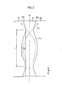
- Fig. 1 is a developed view of a tread which constitutes a pneumatic tire 1 in the reference embodiment. Each portion formed on a tread surface in the pneumatic tire 1 will be described. In particular, (1.1.1) Land Portion (1.1.2) Main groove will be described.
- the pneumatic tire 1 includes a land portion 10, a land portion 20 and a land portion 30 which extend along the circumferential direction R of the tire and come in contact with the road surface.
- the land portion 10 includes a groove wall 10a (which will be described later) which forms a main groove 50 at an end thereof in the width direction W TR of the tread.
- the land portion 20 includes a groove wall 20a (which will be described later) which forms a main groove 50 at an end thereof in the width direction W TR of the tread.
- the land portion 30 includes transverse grooves 110 which open outside in the width direction W TR of the tread.
- the pneumatic tire 1 includes a main groove 50 extending along the circumferential direction R of the tire between the land portion 10 and the land portion 20.
- the pneumatic tire 1 includes a main groove 60 extending along the circumferential direction R of the tire between the land portion 10 and the land portion 30.
- the main groove 50 is provided on an equator line CL of the tire.
- the main groove 60 is provided outside the equator line CL of the tire in the width direction W TR of the tread.
- the structure of one side bordering the equator line CL of the tire in the width direction W TR of the tread has been described. Since the structure of the other side bordering the equator line CL in the width direction W TR of the tread is the same as that described above, detailed description thereof will be omitted.
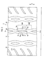
- FIG. 2 illustrates a developed view in which the main groove 50 is enlarged in the tread which constitutes the pneumatic tire 1.
- main groove 60 Since the structure of the main groove 60 is the same as that of the main groove 50, detailed description thereof is omitted.
- the main groove 50 is formed by the groove wall 10a of the land portion 10 and the groove wall 20a of the land portion 20.
- the groove wall 10a and the groove wall 20a are serpentine in the circumferential direction R of the tire when seen from the plane of the tread surface.
- the groove wall 10a and the groove wall 20a are provided symmetrically about the center line of the main groove 50.
- the main groove 50 includes a groove width which changes in the predetermined cycle along the width direction W TR of the tread.
- the groove width of the main groove 50 represents the distance in the width direction W TR of the tread from an arbitrary point on the groove wall 10a to the groove wall 20a.
- a ratio of a minimum-width portion W MIN of the groove width of the main groove 50 and a maximum-width portion W MAX of the groove width of the main groove 50 satisfies a relation of 35% ⁇ W MIN /W MAX ⁇ 85%.
- a relation of (W MAX -W MIN )/A ⁇ 0.25 is satisfied when an average length of the main groove 50 in the width direction W TR of the tread is set to A.
- the groove width of the main groove 50 changes in a cycle ⁇ along the circumferential direction R of the tire.
- the groove wall 10a and the groove wall 20a have an amplitude a along the width direction W TR of the tread.
- the groove wall 10a and the groove wall 20a change in the cycle ⁇ along the circumferential direction R of the tire when seen from the plane of the tread surface.
- the groove wall 10a and the groove wall 20a are provided in symmetrical shapes in the front and rear directions about the maximum-width portion W MAX when the minimum-width portion W MIN is set to the starting point of the cycle ⁇ .
- a relation between the cycle ⁇ which is the cycle in the groove width of the main groove 50 in the circumferential direction R of the tire and is the cycle of the groove wall 10a and the groove wall 20a in the circumferential direction R of the tire and the amplitude a is the following: the cycle ⁇ is 15 times to 100 times the amplitude a.
- the cycle ⁇ of the main groove 50 and the cycle ⁇ of the main groove 60 are out of alignment by a half cycle.
- a relation between the tread length which is the length, in the circumferential direction R of the tire, of the tread which comes in contact with the road surface and the cycle ⁇ of the main groove 50 is the following: the tread length is 0.5 to 20 times the cycle ⁇ .
- a streamline S 10a and a streamline S 20a which are flows of water along the groove wall 10a and the groove wall 20a are produced in the main groove 50.
- Water which flows along the groove wall 10a and the groove wall 20a first passes through the maximum-width portion W MAX and then, as the groove width of the main groove 50 decreases, is expelled in the direction of extension lines of the streamline S 10a and the streamline S 20a at the minimum-width portion W MIN .
- water in the main groove 50 pulses in the cycle ⁇ and is expelled at the minimum-width portion W MIN in the direction of the extension lines of the streamline S 10a and the streamline S 20a .
- the groove wall 10a and the groove wall 20a have the amplitude a along the width direction W TR of the tread and the cycle ⁇ is 15 times to 100 times the amplitude a; thus water which flows in the main groove 50 can be expelled outside the main groove 50 effectively and thus reduction in water expelling capability can be further controlled.
- the cycle ⁇ is more than twice the amplitude a, excessive concentration of the flow along the groove wall 10a and the groove wall 20a and the flow in the circumferential direction at the minimum-width portion W MIN can be sufficiently controlled. Since the cycle ⁇ is 100 times or smaller the amplitude a, water in the main groove 50 can pulse sufficiently and thus water which flows in the main groove 50 can be expelled outside the main groove 50.
- the main groove 50 comes in contact along the circumferential direction R of the tire in the number enough to cause pulsation upon rotation of the tire.
- water which flows in the main groove 50 can be effectively expelled outside the main groove 50.
- the tread length is 20 times or less the cycle ⁇ of the main groove 50, the flows of water along the groove wall 10a and the groove wall 20a are produced in the main groove 50 and thereby water which flows in the main groove 50 can be expelled outside the main groove 50 effectively.
- the groove wall 10a and the groove wall 20a are serpentine along the circumferential direction of the tire in the main groove 50 of the pneumatic tire 1 and the ratio W MIN /W MAX is in the range of 35% to 85%: since water which flows in the main groove 50 can be periodically expelled outside the main groove 50, reduction in water expelling capability of the pneumatic tire 1 is controlled.
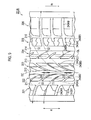
- Fig. 3 is a developed view of a tread which constitutes a pneumatic tire 2 in the first embodiment.
- Fig. 4 is a partially sectioned perspective view illustrating the pneumatic tire 2 according to the first embodiment.
- Fig. 5 is a sectional view (a sectional view taken along line A-A' of Fig. 3 and Fig. 4 ) which illustrates the pneumatic tire 2 according to the first embodiment.
- wide-width portions 50A which include the maximum-width portions W MAX are formed in a main groove 50.
- narrow-width portions 50B which include the minimum-width portions W MIN are formed in the main groove 50.
- the wide-width portions 50A and the narrow-width portions 50B are formed alternately in the circumferential direction R of the tire.
- raised portions 70 which are raised in the radial direction outside the tire are formed on a bottom portion 50btm which is a bottom portion of the main groove 50.
- the raised portions 70 are formed in the widened areas 50A.
- the raised portions 70 are formed in an elongated shape along the circumferential direction R of the tire when seen from the plane of the tread surface.
- the raised portions 70 are tapered, when seen from the plane of the tread surface, toward front ends 70f and rear ends 70r which are ends in the circumferential direction R of the tire.
- a side portion 70a of the raised portion 70 which faces the groove wall 10a which forms the main groove 50 extends along the groove wall 10a.
- a side portion 70b of the raised portion 70 which faces the groove wall 20a which forms the main groove 50 extends along the groove wall 20a.
- the raised portions 70 are provided symmetrically about the center line of the main groove 50 when seen from the plane of the tread surface.
- the raised height H 70 which is the height of the raised portions 70 is the height along the radial direction of the tire from the bottom portion 50btm.
- the height H 70 of the raised portions is smaller than the depth H 10 of the main groove 50 which is the depth of the main groove 50.
- the raised portions 70 are formed to be raised in the radial direction outside the tire on the bottom portion 50btm of the wide-width portion 50A including the maximum-width portion W MAX , the raised portions 70 let water which flows in the wide-width portion 50A be easy to flow along the groove wall 10a and the groove wall 20a. That is, the raised portions 70 let water be expelled outside the main groove 50 and thus reduction in water expelling capability can be further controlled.
- the side portion 70a extends along the groove wall 10a and the side portion 70b extends along the groove wall 20a, water which flows in the wide-width portion 50A is further easy to flow along the groove wall 10a and the groove wall 20a. Accordingly, reduction in water expelling capability can be further controlled.
- the raised portions 70 are tapered, when seen from the plane of the tread surface, toward the front ends 70f and the rear ends 70r, water which flows in the wide-width portion 50A is easy to flow effectively along the groove wall 10a and the groove wall 20a without being interfered rapidly by the raised portions 70.
- the raised portions 70 are provided symmetrically about the center line of the main groove 50 when seen from the plane of the tread surface, the raised portions 70 let water which flows in the wide-width portion 50A be easy to flow uniformly along the groove wall 10a and the groove wall 20a.
- the height H 70 of the raised portions is smaller than the depth H 10 of the main groove, the flow of water along the circumferential direction R of the tire is sufficiently secured in the wide-width portion 50A.
- Hydroplaning performance was evaluated using three kinds of pneumatic tires. Data about the pneumatic tire was measured under the following conditions.
- the evaluation results are expressed as indices with the speed at which hydroplaning occurred in the pneumatic tire of Comparative Example set to 100.
- FIG. 6 A developed view of the tread of the pneumatic tire used in Comparative Example is illustrated in Fig. 6 .
- a pneumatic tire 3 of Comparative Example differs from the pneumatic tires of the Reference Example and Examples in the structures of a main groove 2100 and a main groove 2101.
- groove walls which form the main groove 2100 and the main groove 2101 are not serpentine but are formed substantially linearly along the circumferential direction R of the tire: in this regard, these groove walls differ from the groove wall 10a of the main groove 50 of the pneumatic tire 1 of Example illustrated in Fig. 1 .
- FIG. 7 is a developed view illustrating a tread pattern of the pneumatic tire 200 according to the second embodiment.
- the contact width TW of the tread with respect to the width direction W TR of the tread is 215 mm or greater.
- pneumatic tire 200 includes a plurality of land portions 220 formed by a plurality of main grooves 210 extending in the circumferential direction R of the tire.
- the plurality of main grooves 210 are constituted by a main groove 211, a main groove 212 and a main groove 213 in this order from inside IN (left in Fig. 7 ) toward outside OUT (right in Fig. 7 ) when seen from the direction in which the tire is mounted on a vehicle.
- the main groove 211 extends linearly along the circumferential direction R of the tire.
- the main groove 211 is provided inside IN of an equator line CL of the tire when seen from the direction in which the tire is mounted on a vehicle.
- the main groove 212 is a groove which most greatly contributes to water expelling performance among the plurality of main grooves 210.
- the main groove 212 has a groove width W along the width direction of the tread which varies along the circumferential direction of the tire.
- Raised portions 230 are formed on a bottom portion 112F of the main groove 212 to be raised outward in the radial direction of the tire.
- the main groove 212 is provided inside IN of an equator line CL of the tire when seen from the direction in which the tire is mounted on a vehicle.
- the distance D from the equator line CL of the tire to the main groove 212 (i.e., the offset distance) is 9 to 25% of the contact width TW of the tread with respect to the width direction of the tread. Structures of the main groove 212 and the raised portions 230 will be described later.
- the main groove 213 extends linearly along the circumferential direction of the tire.
- the main groove 213 has the groove width W along the width direction of the tread which varies along the circumferential direction of the tire depending on the shape of a land portion 223 or a land portion 224 which will be described later.
- the main groove 213 is provided outside OUT of an equator line CL of the tire when seen from the direction in which the tire is mounted on a vehicle.
- the land portion 220 includes a land portion 221, a land portion 222, a land portion 223 and a land portion 224 in this order from inside IN toward outside OUT when seen from the direction in which the tire is mounted on a vehicle.
- the land portion 221 is formed inside IN with respect to the main groove 211 when seen from the direction in which the tire is mounted on a vehicle.
- the land portion 222 is formed by the main groove 211 and the main groove 212.
- the land portion 223 is formed by the main groove 212 and the main groove 213.
- the land portion 224 is formed outside OUT with respect to the main groove 213 when seen from the direction in which the tire is mounted on a vehicle.
- Lug grooves 240 extending in the width direction of the tread are formed in the land portion 220 (i.e., the land portion 221 to the land portion 224).
- the structure of the lug grooves 240 will be described later.
- FIG. 8 is a developed view in which a neighborhood of the main groove 212 is enlarged according to the second embodiment.
- the land portion 222 (the first land portion) situated inside IN of the main groove 212 when seen from the direction in which the tire is mounted on a vehicle includes a groove wall 222A (the first groove wall) which forms one of the wall surfaces of the main groove 212.
- the land portion 223 (the second land portion) situated outside OUT of the main groove 212 when seen from the direction in which the tire is mounted on a vehicle includes a groove wall 223A (the second groove wall) which forms one of the wall surface of the main groove 212.
- the groove wall 222A and the groove wall 223A are serpentine in the circumferential direction of the tire when seen from the plane of the tread surface.
- the groove wall 222A and the groove wall 223A pass along center of main groove 212 to width direction of the tread, and are symmetrically provided to main groove center line DC extended along circumferential direction of the tire.
- the groove width W of the main groove 212 along the width direction of the tread varies in the predetermined repetition cycle along the circumferential direction of the tire.
- the groove width W of the main groove 212 represents the distance in the width direction of the tread from an arbitrary point on the groove wall 222A to the groove wall 223A.
- Wide-width portions 212A and narrow-width portions 212B are provided in the main groove 212.
- the wide-width portions 212A include a maximum-width portion W MAX of the groove width W of the main groove 212 along the width direction of the tread.
- the narrow-width portions 212B include a minimum-width portion W MIN of the groove width W of the main groove 212 along the width direction of the tread.
- the wide-width portions 212A and the narrow-width portions 212B are arranged alternately along the circumferential direction of the tire.
- a ratio of the minimum-width portion W MIN of the groove width W of the narrow-width portions 212B and the maximum-width portion W MAX of the groove width W of the wide-width portions 212A satisfies a relation of 35% ⁇ W MIN /W MAX ⁇ 85%.
- the groove wall 222A and the groove wall 223A have a predetermined amplitude a along the width direction of the tread.
- the groove wall 222A and the groove wall 223A change in the cycle ⁇ along the circumferential direction of the tire when seen from the plane of the tread surface.
- the groove wall 222A and the groove wall 223A are formed in symmetrical shapes in the front and rear directions of the rotational direction Rt of the tire about the maximum-width portion W MAX when the minimum-width portion W MIN is set to the starting point of the cycle ⁇ .
- the cycle ⁇ of the groove wall 222A and the groove wall 223A in the circumferential direction of the tire is 15 times to 100 times the amplitude a.
- the tread length in the circumferential direction of the tire of the tread which comes in contact with the road surface is 0.5 to 20 times the cycle ⁇ of the main groove 212 during rotation of the tire.
- Fig. 4 is applicable to the description of a section illustrating a neighborhood of the main groove 212 according to the second embodiment.
- Fig. 5 is applicable to the description of a section illustrating a neighborhood of the main groove 212 according to the second embodiment.
- the raised portions 230 are formed in the wide-width portions 212A.
- the raised portions 230 are formed in an elongated shape along the circumferential direction of the tire when seen from the plane of the tread surface.
- the raised portions 230 When seen from the plane of the tread surface, the raised portions 230 are tapered toward a front end 230a (the front end portion) in the front direction of the rotational direction Rt of the tire and toward a rear end 230b (the rear end portion) in the rear direction of the rotational direction Rt of the tire. Side portions 230c (the first side portion) of the raised portions 230 which face the groove wall 222A extend along the groove wall 222A. Side portions 230d (the second side portion) of the raised portions 230 which face the groove wall 223A extend along the groove wall 223A.
- the raised portions 230 are provided symmetrically about the center line DC of the main groove when seen from the plane of the tread surface.
- the height H of the raised portions 230 is preferably smaller than the depth D of the main groove 212.
- the lug grooves 240 are constituted by dividing lug grooves 240A and end lug grooves 240B.
- the dividing lug grooves 240A and the end lug grooves 240B are inclined with respect to the circumferential direction of the tire so as to extend toward the rotational direction Rt of the tire and outward in the width direction of the tread.
- the dividing lug grooves 240A and the end lug grooves 240B extend in a curved manner from the front to the rear in the rotational direction Rt of the tire.
- the dividing lug grooves 240A divide the land portion 220 in the width direction of the tread and communicates with the main groove 210.
- the dividing lug grooves 240A are constituted by dividing lug grooves 240A1 formed in the land portion 221, dividing lug grooves 240A2 formed in the land portion 222, dividing lug grooves 240A3 formed in the land portion 223 and dividing lug grooves 240A4 formed in the land portion 224.
- end lug grooves 240B terminate at the land portion 220.
- the end lug grooves 240B are constituted by end lug grooves 240B2 formed in the land portion 222, end lug grooves 240B3 formed in the land portion 223 and end lug grooves 240B4 formed in the land portion 224. No end lug groove 240B is formed in the land portion 221.
- the dividing lug grooves 240A2 and the dividing lug grooves 240A3 communicate with the wide-width portion 212A.
- either one of the dividing lug grooves 240A2 and the dividing lug grooves 240A3 are preferably provided on an extension line EX along the groove wall 222A and the groove wall 223A which form the maximum-width portion W MAX of the groove width of the wide-width portion 212A from the groove wall 222A and the groove wall 223A which form the minimum-width portion W MIN of the groove width of the narrow-width portion 212B.
- the dividing lug grooves 240A2 and the dividing lug grooves 240A3 are provided asymmetrically about the center line DC of the main groove in order to mitigate noise.
- the dividing lug grooves 240A1 are provided along extension lines S1 along the extending direction of the dividing lug grooves 240A2.
- the dividing lug grooves 240A4 are provided along extension lines S2 along the extending direction of the dividing lug grooves 240A3.
- the end lug grooves 240B2 are provided between the dividing lug grooves 240A2 which are adjacent to each other in the circumferential direction of the tire.
- the end lug grooves 240B1 are provided along extension lines T1 along the extending direction of the end lug grooves 240B2.
- the end lug grooves 240B3 are provided between the dividing lug grooves 240A3 which are adjacent to each other in the circumferential direction of the tire.
- the end lug grooves 240B4 are provided along extension lines T2 along the extending direction of the end lug grooves 240B3.
- the groove wall 222A and the groove wall 223A are serpentine in the circumferential direction of the tire when seen from the plane of the tread surface and the groove width W of the main groove 212 changes in predetermined cycle ⁇ along the circumferential direction of the tire. According to this, a flow of water along the serpentine shape of the groove wall 222A and the groove wall 223A is produced in the main groove 212. Water flowing in the main groove 212 pulses in the predetermined cycle ⁇ and is easy to be expelled in the direction of the extension lines of the streamlines along the groove wall 222A and the groove wall 223A from the maximum-width portion W MAX toward the minimum-width portion W MIN . Therefore, water expelling performance to expel water trapped between the road surface and the tread can be improved further reliably.
- the main groove 212 described above is provided inside IN of the equator line CL of the tire when seen from the direction in which the tire is mounted on a vehicle. According to this, in a case in which the tire is mounted on the vehicles in which a negative camber angle is set, the main groove 212 is situated near the center on the contact surface of the tread which is in contact with the road surface. Therefore, water expelling performance can be further improved as compared with a case in which the main groove 212 is situated on the equator line CL of the tire.
- the lug grooves 240 are formed in at least one of the land portion 222 and the land portion 223. According to this, water trapped between a wheel tread (which is a surface of the land portion 222 or the land portion 223) of the tread and the road surface flows into the lug grooves 240 and is easier to be expelled outward in the width direction of the tread as compared with a case in which no lug groove is formed. Especially the lug grooves 240, which communicate with the main groove 212, promotes reliable expulsion outward in the width direction of the tread. Therefore, water expelling performance can be improved further reliably.
- the ratio of the minimum-width portion W MIN of the groove width W of the main groove 212 and the maximum-width portion W MAX of the groove width W of the main groove 212 i.e., W MIN /W MAX .
- W MIN /W MAX water which flows along the groove wall 222A and the groove wall 223A passes through the maximum-width portion W MAX and then, as the groove width W of the main groove 212 decreases, is easy to be expelled at the minimum-width portion W MIN in the direction of the extension lines of the streamlines along the groove wall 222A and the groove wall 223A. That is, water in the main groove is easy to be directed outward in the width direction of the tread. Therefore, water expelling performance can be improved further reliably.
- the ratio W MIN /W MAX is 35% or more, the flow along the groove wall 222A and the groove wall 223A and the flow along the circumferential direction of the tire do not concentrate excessively at the minimum-width portion W MIN and reduction in water expelling capability can be controlled further reliably. Since, on the other hand, the ratio W MIN /W MAX is 85% or less, water in the main groove 212 is easy to pulse and thus water expelling performance can be improved further reliably.
- the lug grooves 240 (the dividing lug grooves 240A2 and the dividing lug grooves 240A3) communicate the wide-width portion 212A.
- water which flows along the groove wall 222A and the groove wall 223A passes through the maximum-width portion W MAX and then, as the groove width W of the main groove 212 decreases, is easy to be expelled at the minimum-width portion W MIN in the direction of the extension lines of the streamlines along the groove wall 222A and the groove wall 223A. That is, water in the main groove 212 is easy to be directed outward in the width direction of the tread.
- the distance D from the equator line CL of the tire to the main groove 212 is 9 to 25% of the contact width TW of the tread with respect to the width direction of the tread.
- the main groove 212 is situated near the center on the contact surface of the tread which is in contact with the road surface so as to allow setting of various camber angles. It is therefore possible to manufacture the pneumatic tire 200 corresponding to various camber angles.
- the main groove 212 is easy to be situated near the center of the contact surface of the tread which is in contact with the road surface in a state in which the camber angle is set, and thus it is easy to control reduction in water expelling performance.
- the cycle ⁇ is 15 times to 100 times the amplitude a. According to this, since water which flows in the main groove 212 can be effectively expelled outside the main groove 212, water expelling performance can be improved further reliably.
- the raised portions 230 which are raised outward in the radial direction of the tire are formed in the bottom portion 112F in the wide-width portion 212A of the main groove 212.
- the raised portions 230 let water which flows in the wide-width portion 212A be easy to flow along the groove wall 222A and the groove wall 223A. That is, the raised portions 230 let water which flows in the wide-width portion 212A be easy to be expelled into the lug grooves 240 (the dividing lug grooves 240A2 and the dividing lug grooves 240A3).
- water which flows in the wide-width portion 212A can be expelled efficiently and water expelling performance can be improved further reliably.
- the side portions 230c of the raised portions 230 which face the groove wall 222A extend along the groove wall 222A and the side portions 230c of the raised portions 230 which face the groove wall 223A extend along the groove wall 223A. According to this, water which flows in the wide-width portion 212A is further easy to flow along the groove wall 222A and the groove wall 223A.
- the raised portions 230 are tapered toward the front end 30a in the rotational direction Rt of the tire and the rear end 30b in the rotational direction Rt of the tire when seen from the plane of the tread surface. According to this, water which flows in the wide-width portion 212A is easy to flow effectively along the groove wall 222A and the groove wall 223A without being interfered rapidly by the raised portions 230.
- the raised portions 230 are provided symmetrically about the center line DC of the main groove when seen from the plane of the tread surface. According to this, the raised portions 230 let water which flows in the wide-width portion 212A be easy to flow uniformly along the groove wall 222A and the groove wall 223A.
- the height H of the raised portions 230 is smaller than the depth D of the main groove 212. According to this, the flow of water along the circumferential direction of the tire is sufficiently secured in the wide-width portion 212A as compared with a case in which the height H of the raised portions 230 is greater than the depth D of the main groove 212.
- a pneumatic tire 200A according to a third embodiment according to the present invention will be described with reference to the drawings.
- many main grooves 210 and land portions 220 of the pneumatic tire 1 according to the second embodiment are provided.
- (5.1) Structure of Pneumatic Tire, (5.2) Structure of Lug Grooves and (5.3) Operation and Effect will be described.
- the same reference numerals are given to the same portions as those of the pneumatic tire 200 according to the second embodiment described above, and different portions will be described mainly.
- FIG. 9 is a developed view illustrating a tread pattern of the pneumatic tire 200A according to the third embodiment.
- the contact width TW of the tread with respect to the width direction W TR of the tread is 303 mm or greater.
- a main groove 210 is constituted by a main groove 211, a main groove 212, a main groove 213, a main groove 214 and a main groove 215 in this order from inside IN toward outside OUT when seen from the direction in which the tire is mounted on a vehicle.
- the main groove 214 and the main groove 215 extend linearly along the circumferential direction of the tire.
- Other structure of the main grooves 210 is the same as the details described in the second embodiment.
- a land portion 220 includes a land portion 221, a land portion 222, a land portion 223, a land portion 224, a land portion 225 and a land portion 226 in this order from inside IN toward outside OUT when seen from the direction in which the tire is mounted on a vehicle.
- the land portion 225 is formed by a main groove 214 and a main groove 215.
- the land portion 226 is formed outside OUT with respect to the main groove 215 when seen from the direction in which the tire is mounted on a vehicle.
- Other structure of the land portions 220 is the same as the details described in the second embodiment.
- the lug grooves 240 are constituted by dividing lug grooves 240A and end lug grooves 240B.
- the dividing lug grooves 240A and the end lug grooves 240B are inclined with respect to the circumferential direction of the tire.
- the dividing lug grooves 240A and the end lug grooves 240B extend in a curved manner from the front to the rear in the rotational direction Rt of the tire.
- the dividing lug grooves 240A are constituted by, in addition to the dividing lug grooves 240A1, the dividing lug grooves 240A2 and the dividing lug grooves 240A3, dividing lug grooves 240A5 formed in the land portion 225 and dividing lug grooves 240A6 formed in the land portion 226. No dividing lug groove 240A is formed in the land portion 224.
- the end lug grooves 240B are constituted by, in addition to the end lug grooves 240B2, the end lug grooves 240B3 and the end lug grooves 240B4, end lug grooves 240B1 formed in the land portion 221 and end lug grooves 240 B5 formed in the land portion 225. No end lug groove 240B is formed in the land portion 226.
- the dividing lug grooves 240A5 and the dividing lug grooves 240A6 are provided along extension lines S2 along the extending direction of the dividing lug grooves 240A3. That is, the end lug grooves 240B4 intersect the extension lines S2 and extend in a curved manner in the direction opposite to the extension lines S2.
- a linear groove (for example, a wide groove) which most greatly contributes to water expelling performance among a plurality of main grooves is provided on the equator line CL of the tire.
- a linear groove (for example, a wide groove) which most greatly contributes to water expelling performance among a plurality of main grooves is provided inside IN with respect to the equator line CL of the tire when seen from the direction in which the tire is mounted on a vehicle.
- the main groove 212 which most greatly contributes to water expelling performance among the main grooves 210 is provided inside IN with respect to the equator line CL of the tire when seen from the direction in which the tire is mounted on a vehicle.
- the pneumatic tire 200 described in the second embodiment is used as a front wheel and the pneumatic tire 200A described in the third embodiment is used as a rear wheel.
- a vehicle on which each of the pneumatic tires is mounted is made to run at a speed of 80 km/h.
- the speed is increased while only the right wheel mounted on the vehicle is running on a rainy road at a depth of 10 mm.
- the speed at which speed difference (i.e., a skid) between the right and left wheels mounted on the vehicle occurs is set to "hydroplaning occurring speed.” Measurement was made five times and an average speed was measured excluding the maximum and minimum values.
- the vehicle on which the pneumatic tire according to Examples is mounted had higher hydroplaning occurring speed than that of the vehicle on which the pneumatic tire according to Comparative Examples 1 and 2 is mounted, and thus can control the occurrence of hydroplaning.
- the groove wall 10a and the groove wall 20a are serpentine in a repetitive manner along the circumferential direction R of the tire when seen from the plane of the tread surface in the embodiments described above; however, it is not necessary that the groove wall 10a and the groove wall 20a are serpentine in a repetitive manner and may be provided, for example, linearly along the circumferential direction R of the tire.
- the groove wall 10a and the groove wall 20a change in a predetermined repetition cycle along the circumferential direction R of the tire when seen from the plane of the tread surface, and are provided symmetrically in the front and rear direction about the maximum-width portion W MAX within a cycle. It is not necessary, however, that the groove wall 10a and the groove wall 20a are provided symmetrically in the front and rear direction about the maximum-width portion W MAX within a cycle; for example, the groove wall 10a and the groove wall 20a may be provided in a shape in which the groove width is rapidly reduced on the rear side.
- the contact width TW of the tread of the pneumatic tire 100 is 215 mm or greater in the second embodiment and the contact width TW of the tread to width direction of the tread of the pneumatic tire 100A is 303 mm or greater in the third embodiment; however, these are not restrictive and the contact width TW of the tread with respect to the width direction of the tread may be smaller than 215 m and 303 mm.
- a plurality of land portions 220 are formed by a plurality of main grooves 210; however, this is not restrictive and two land portions 220 may be formed by at least one main groove 210.
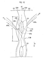
- the groove wall 222A and the groove wall 223A are provided symmetrically about the center line DC of the main groove; however, this is not restrictive and the groove wall 222A and the groove wall 223A may be provided asymmetrically about the center line DC of the main groove as illustrated in Fig. 10 .
- the main groove 212 which most greatly contributes to water expelling performance among a plurality of main grooves 210 is provided inside IN with respect to the equator line CL of the tire when seen from the direction in which the tire is mounted on a vehicle; however, this is not restrictive and the major groove 212 may be provided It may be provided outside OUT with respect to the equator line CL of the tire when seen from the direction in which the tire is mounted on a vehicle. This case is effective when the tire is mounted on a vehicle in which a positive camber angle is set.
- the raised portions 230 are provided on the bottom portion (not illustrated) of the main groove 212; however, this is not restrictive and no raised portion 230 may be provided.
- the shape of the raised portion 230 may be suitably changed according to the purpose.
- the lug grooves 240 are constituted by the dividing lug grooves 240A and the end lug grooves 240B; however, this is not restrictive and either of the dividing lug grooves 240A or the end lug grooves 240B may be provided.
- the dividing lug grooves 240A and the end lug grooves 240B are inclined with respect to the circumferential direction of the tire; however, this is not restrictive and the dividing lug grooves 240A and the end lug grooves 240B may be provided along the width direction of the tread.
- the dividing lug grooves 240A and the end lug grooves 240B do not necessarily extend in a curved manner but may extend linearly.
- the dividing lug groove 240A2 and the dividing lug groove 240A3 communicate with the main groove 212 (wide-width portion 212A); however, this is not restrictive and, for example, one ends of the end lug grooves 240B may communicate with the main groove 212. It is not necessary that the dividing lug grooves 240A2 and the dividing lug grooves 240A3 communicate with the wide-width portion 212A; however, the dividing lug grooves 240A2 and the dividing lug grooves 240A3 may be situated close to the wide-width portion 212A or may communicate with or may be situated close to the narrow-width portion 212B.
- the dividing lug groove 240A2 and the dividing lug groove 240A3 are provided asymmetrically about the center line DC of the main groove in order to mitigate noise; however, this is not restrictive and the dividing lug groove 240A2 and the dividing lug groove 240A3 may be provided symmetrically about the center line DC of the main groove.
- the shape of the lug grooves 240 may be suitably changed according to the purpose.
- the present invention since the number of the transverse grooves which intersect the main groove can be minimized and reduction in water expelling capability can be controlled, the present invention can be applied to pneumatic tires which are excellent in design and appearance.
Landscapes
- Engineering & Computer Science (AREA)
- Mechanical Engineering (AREA)
- Tires In General (AREA)
Claims (9)
- Luftreifen, der Folgendes umfasst:einen ersten Stegabschnitt (10), der sich entlang einer Umfangsrichtung des Reifens erstreckt und in Berührung mit einer Straßenoberfläche kommt, undeinen zweiten Stegabschnitt (20), der sich entlang der Umfangsrichtung des Reifens erstreckt und in Berührung mit der Straßenoberfläche kommt,wobei eine Hauptrille (50), die sich entlang der Umfangsrichtung des Reifens erstreckt, zwischen dem ersten Stegabschnitt (10) und dem zweiten Stegabschnitt (20) geformt ist,wobei:der erste Stegabschnitt (10) eine erste Rillenwand (10a) einschließt, welche die Hauptrille (50) bildet,der zweite Stegabschnitt (20) eine zweite Rillenwand (20a) einschließt, welche die Hauptrille (50) bildet,die erste Rillenwand (10a) und die zweite Rillenwand (20a) schlangenförmig entlang der Umfangsrichtung des Reifens sind, wenn sie von einer Ebene der Laufflächenoberfläche aus betrachtet werden,eine Rillenbreite der Hauptrille (50) entlang einer Breitenrichtung sich in einem vorbestimmten Wiederholungszyklus entlang der Umfangsrichtung des Reifens verändert undein Verhältnis eines Abschnitts mit minimaler Breite WMIN der Rillenbreite und eines Abschnitts mit maximaler Breite WMAX der Rillenbreite eine Beziehung von 35 % ≤ WMIN/WMAX ≤ 85 % erfüllt, dadurch gekennzeichnet, dass:die Hauptrille (50) einen Rillenabschnitt (50A) mit breiter Breite bildet, der den Abschnitt mit maximaler Breite WMAX einschließt,ein erhöhter Abschnitt (70a), der in einer radialen Richtung des Reifens nach außen erhöht ist, in einem Bodenabschnitt der Hauptrille (50) geformt ist, undder erhöhte Abschnitt (70a) in dem Rillenabschnitt (50A) mit breiter Breite geformt ist.
- Luftreifen nach Anspruch 1, wobei eine Beziehung von (WMIN·WMAX)/A ≤ 0,25 % erfüllt ist, wobei eine durchschnittliche Länge entlang der Breitenrichtung der Lauffläche der Hauptrille (50) auf A festgesetzt ist.
- Luftreifen nach Anspruch 1, wobei eine Stollenrille (240A1..240B4), die sich in der Breitenrichtung der Lauffläche erstreckt, in wenigstens einem von dem ersten Stegabschnitt (10) und dem zweiten Stegabschnitt (20) geformt ist.
- Luftreifen nach Anspruch 1, wobei:die Stollenrille (240A1..240B4) in Bezug auf die Umfangsrichtung des Reifens geneigt ist und mit dem Rillenabschnitt (50A) mit breiter Breite verbunden oder nahe demselben angeordnet ist.
- Luftreifen nach Anspruch 1, wobei eine Entfernung von der Äquatorlinie des Reifens zu der Hauptrille (50) 9 bis 25 % in Bezug auf eine Berührungsbreite der Lauffläche in Bezug auf die Breitenrichtung der Lauffläche beträgt.
- Luftreifen nach Anspruch 1, wobei die erste Rillenwand (10a) und die zweite Rillenwand (20a) eine vorbestimmte Amplitude entlang der Breitenrichtung der Lauffläche haben und der vorbestimmte Wiederholungszyklus das 15-fache bis 100-fache der vorbestimmten Amplitude beträgt.
- Luftreifen nach Anspruch 1, wobei sich ein erster Seitenabschnitt (70a) des erhöhten Abschnitts (70), welcher der ersten Rillenwand (10a) gegenüberliegt, entlang der ersten Rillenwand (10a) erstreckt und sich ein zweiter Seitenabschnitt (70b) des erhöhten Abschnitts (70), welcher der zweiten Rillenwand (20a) gegenüberliegt, entlang der zweiten Rillenwand (20a) erstreckt.
- Luftreifen nach Anspruch 7, wobei der erhöhte Abschnitt (70) zu einem vorderen Endabschnitt und einem hinteren Endabschnitt hin verjüngt ist, wenn er von einer Ebene der Laufflächenoberfläche aus betrachtet wird.
- Luftreifen nach Anspruch 8, wobei die Höhe des erhöhten Abschnitts (70) kleiner ist als die Tiefe der Hauptrille (50).
Applications Claiming Priority (3)
| Application Number | Priority Date | Filing Date | Title |
|---|---|---|---|
| JP2009027705A JP5468789B2 (ja) | 2009-02-09 | 2009-02-09 | 空気入りタイヤ |
| JP2009139242A JP5320172B2 (ja) | 2009-06-10 | 2009-06-10 | 空気入りタイヤ |
| PCT/JP2010/051875 WO2010090327A1 (ja) | 2009-02-09 | 2010-02-09 | 空気入りタイヤ |
Publications (3)
| Publication Number | Publication Date |
|---|---|
| EP2394823A1 EP2394823A1 (de) | 2011-12-14 |
| EP2394823A4 EP2394823A4 (de) | 2013-05-22 |
| EP2394823B1 true EP2394823B1 (de) | 2014-04-30 |
Family
ID=42542212
Family Applications (1)
| Application Number | Title | Priority Date | Filing Date |
|---|---|---|---|
| EP10738655.9A Not-in-force EP2394823B1 (de) | 2009-02-09 | 2010-02-09 | Luftreifen |
Country Status (5)
| Country | Link |
|---|---|
| US (1) | US9452643B2 (de) |
| EP (1) | EP2394823B1 (de) |
| CN (1) | CN102307736B (de) |
| BR (1) | BRPI1008662A2 (de) |
| WO (1) | WO2010090327A1 (de) |
Families Citing this family (11)
| Publication number | Priority date | Publication date | Assignee | Title |
|---|---|---|---|---|
| JP5366852B2 (ja) * | 2010-02-09 | 2013-12-11 | 株式会社ブリヂストン | タイヤ |
| JP5635170B1 (ja) | 2013-10-23 | 2014-12-03 | 株式会社ブリヂストン | 空気入りタイヤ |
| FI125377B (fi) * | 2014-01-17 | 2015-09-15 | Nokian Renkaat Oyj | Ajoneuvon rengas |
| CN104015569A (zh) * | 2014-05-26 | 2014-09-03 | 厦门正新橡胶工业有限公司 | 雨天比赛专用摩托车轮胎胎面花纹结构 |
| DE102014225613A1 (de) * | 2014-12-11 | 2016-06-16 | Continental Reifen Deutschland Gmbh | Fahrzeugluftreifen |
| NO2795041T3 (de) * | 2015-06-01 | 2018-01-27 | ||
| DE102017219532A1 (de) | 2017-11-03 | 2019-05-09 | Continental Reifen Deutschland Gmbh | Nutzfahrzeugreifen |
| JP7027908B2 (ja) * | 2018-01-23 | 2022-03-02 | 住友ゴム工業株式会社 | タイヤ |
| JP7027907B2 (ja) * | 2018-01-23 | 2022-03-02 | 住友ゴム工業株式会社 | タイヤ |
| US20230339269A1 (en) * | 2019-09-24 | 2023-10-26 | Bridgestone Corporation | Motorbike tire |
| CN111873719A (zh) * | 2020-08-12 | 2020-11-03 | 合肥工业大学 | 低噪声轮胎中主沟槽降噪结构 |
Family Cites Families (24)
| Publication number | Priority date | Publication date | Assignee | Title |
|---|---|---|---|---|
| FR997729A (fr) * | 1949-09-17 | 1952-01-11 | Dunlop Sa | Bandage pneumatique |
| US4462446A (en) * | 1982-04-23 | 1984-07-31 | The Goodyear Tire & Rubber Company | Pneumatic tire tread |
| JPH064365B2 (ja) * | 1986-07-17 | 1994-01-19 | 住友ゴム工業株式会社 | 重車両用空気入りタイヤ |
| JPH05254313A (ja) * | 1992-03-16 | 1993-10-05 | Bridgestone Corp | 空気入りタイヤ |
| DE69311504T2 (de) * | 1992-11-13 | 1997-10-02 | Sumitomo Rubber Ind | Luftreifen |
| JP2667771B2 (ja) | 1992-11-13 | 1997-10-27 | 住友ゴム工業株式会社 | 空気入りタイヤ |
| JPH06239108A (ja) * | 1993-02-19 | 1994-08-30 | Ohtsu Tire & Rubber Co Ltd :The | タイヤの石詰まり防止構造 |
| JP3365653B2 (ja) * | 1993-07-13 | 2003-01-14 | 住友ゴム工業株式会社 | 空気入りタイヤ |
| US5472030A (en) | 1993-11-05 | 1995-12-05 | Sumitomo Rubber Industries, Ltd. | Pneumatic tire |
| JPH07276920A (ja) * | 1994-04-07 | 1995-10-24 | Bridgestone Corp | 空気入りタイヤ |
| JPH07329512A (ja) | 1994-06-13 | 1995-12-19 | Bridgestone Corp | 空気入りラジアルタイヤ |
| JPH0811508A (ja) * | 1994-06-30 | 1996-01-16 | Bridgestone Corp | 空気入りタイヤ |
| JPH10151914A (ja) * | 1996-11-21 | 1998-06-09 | Yokohama Rubber Co Ltd:The | 重荷重用空気入りラジアルタイヤ |
| JP3675595B2 (ja) * | 1996-12-06 | 2005-07-27 | 株式会社ブリヂストン | 乗用車用空気入りタイヤ |
| JP4499883B2 (ja) | 1999-07-26 | 2010-07-07 | 住友ゴム工業株式会社 | 空気入りタイヤ |
| JP2002225511A (ja) | 2001-01-31 | 2002-08-14 | Yokohama Rubber Co Ltd:The | 自動車用空気入りタイヤのトレッドパターン |
| US6601624B2 (en) * | 2001-07-11 | 2003-08-05 | The Goodyear Tire & Rubber Company | Tread groove noise diffusers |
| JP3354563B1 (ja) * | 2001-08-22 | 2002-12-09 | 住友ゴム工業株式会社 | 冬用タイヤ |
| JP4428914B2 (ja) | 2002-08-30 | 2010-03-10 | 株式会社ブリヂストン | 非対称トレッドパターンを有するタイヤおよびその装着方法 |
| JP4505290B2 (ja) * | 2004-09-07 | 2010-07-21 | 株式会社ブリヂストン | 空気入りタイヤ |
| JP4529680B2 (ja) * | 2004-12-27 | 2010-08-25 | 横浜ゴム株式会社 | 空気入りタイヤ |
| JP4613623B2 (ja) | 2005-01-26 | 2011-01-19 | 横浜ゴム株式会社 | 空気入りタイヤ |
| US7778659B2 (en) | 2007-07-20 | 2010-08-17 | Mitsubishi Electric Research Laboratories, Inc. | Multiple access by varying received power in wireless networks |
| JP2009139242A (ja) | 2007-12-07 | 2009-06-25 | Renesas Technology Corp | マイクロコンピュータ、データ処理システム及びデータ処理方法 |
-
2010
- 2010-02-09 EP EP10738655.9A patent/EP2394823B1/de not_active Not-in-force
- 2010-02-09 CN CN201080007179.3A patent/CN102307736B/zh not_active Expired - Fee Related
- 2010-02-09 US US13/148,418 patent/US9452643B2/en not_active Expired - Fee Related
- 2010-02-09 BR BRPI1008662A patent/BRPI1008662A2/pt active Search and Examination
- 2010-02-09 WO PCT/JP2010/051875 patent/WO2010090327A1/ja not_active Ceased
Also Published As
| Publication number | Publication date |
|---|---|
| US20120018068A1 (en) | 2012-01-26 |
| CN102307736B (zh) | 2014-02-26 |
| BRPI1008662A2 (pt) | 2016-03-08 |
| CN102307736A (zh) | 2012-01-04 |
| EP2394823A1 (de) | 2011-12-14 |
| WO2010090327A1 (ja) | 2010-08-12 |
| US9452643B2 (en) | 2016-09-27 |
| EP2394823A4 (de) | 2013-05-22 |
Similar Documents
| Publication | Publication Date | Title |
|---|---|---|
| EP2394823B1 (de) | Luftreifen | |
| US10675917B2 (en) | Tire | |
| EP1872973B1 (de) | Luftreifen | |
| KR101851022B1 (ko) | 공기 타이어 | |
| CN108297623B (zh) | 轮胎 | |
| KR101857822B1 (ko) | 공기 타이어 | |
| KR102065609B1 (ko) | 공기 타이어 | |
| EP2193935B1 (de) | Luftreifen mit asymmetrischem Profilmuster | |
| EP3093163B1 (de) | Luftreifen | |
| CN102883892B (zh) | 轮胎 | |
| KR20100111233A (ko) | 공기 타이어 | |
| EP2881266B1 (de) | Luftreifen | |
| EP3078507A1 (de) | Luftreifen | |
| EP2123486A1 (de) | Luftreifen | |
| EP2692543A1 (de) | Luftreifen | |
| KR101898453B1 (ko) | 공기입 타이어 | |
| EP3124291A1 (de) | Schwerlastluftreifen | |
| CN110481245B (zh) | 不平整地面行驶用的摩托车用轮胎 | |
| JP4466765B2 (ja) | 空気入りタイヤ | |
| EP2862728B1 (de) | Reifen | |
| JP5743328B2 (ja) | タイヤ | |
| CN111376653A (zh) | 不平整地行驶用轮胎 | |
| EP4079540B1 (de) | Reifen | |
| JP5580073B2 (ja) | タイヤ | |
| JP2011168221A (ja) | タイヤ |
Legal Events
| Date | Code | Title | Description |
|---|---|---|---|
| PUAI | Public reference made under article 153(3) epc to a published international application that has entered the european phase |
Free format text: ORIGINAL CODE: 0009012 |
|
| 17P | Request for examination filed |
Effective date: 20110826 |
|
| AK | Designated contracting states |
Kind code of ref document: A1 Designated state(s): AT BE BG CH CY CZ DE DK EE ES FI FR GB GR HR HU IE IS IT LI LT LU LV MC MK MT NL NO PL PT RO SE SI SK SM TR |
|
| DAX | Request for extension of the european patent (deleted) | ||
| A4 | Supplementary search report drawn up and despatched |
Effective date: 20130418 |
|
| RIC1 | Information provided on ipc code assigned before grant |
Ipc: B60C 11/03 20060101ALI20130412BHEP Ipc: B60C 11/04 20060101AFI20130412BHEP Ipc: B60C 11/13 20060101ALI20130412BHEP |
|
| RIC1 | Information provided on ipc code assigned before grant |
Ipc: B60C 11/13 20060101ALI20130919BHEP Ipc: B60C 11/04 20060101AFI20130919BHEP Ipc: B60C 11/03 20060101ALI20130919BHEP |
|
| GRAP | Despatch of communication of intention to grant a patent |
Free format text: ORIGINAL CODE: EPIDOSNIGR1 |
|
| INTG | Intention to grant announced |
Effective date: 20131111 |
|
| GRAS | Grant fee paid |
Free format text: ORIGINAL CODE: EPIDOSNIGR3 |
|
| GRAA | (expected) grant |
Free format text: ORIGINAL CODE: 0009210 |
|
| AK | Designated contracting states |
Kind code of ref document: B1 Designated state(s): AT BE BG CH CY CZ DE DK EE ES FI FR GB GR HR HU IE IS IT LI LT LU LV MC MK MT NL NO PL PT RO SE SI SK SM TR |
|
| REG | Reference to a national code |
Ref country code: GB Ref legal event code: FG4D Ref country code: CH Ref legal event code: EP |
|
| REG | Reference to a national code |
Ref country code: AT Ref legal event code: REF Ref document number: 664847 Country of ref document: AT Kind code of ref document: T Effective date: 20140515 |
|
| REG | Reference to a national code |
Ref country code: IE Ref legal event code: FG4D |
|
| REG | Reference to a national code |
Ref country code: DE Ref legal event code: R096 Ref document number: 602010015616 Country of ref document: DE Effective date: 20140612 |
|
| REG | Reference to a national code |
Ref country code: AT Ref legal event code: MK05 Ref document number: 664847 Country of ref document: AT Kind code of ref document: T Effective date: 20140430 |
|
| REG | Reference to a national code |
Ref country code: LT Ref legal event code: MG4D |
|
| REG | Reference to a national code |
Ref country code: NL Ref legal event code: VDEP Effective date: 20140430 |
|
| PG25 | Lapsed in a contracting state [announced via postgrant information from national office to epo] |
Ref country code: BG Free format text: LAPSE BECAUSE OF FAILURE TO SUBMIT A TRANSLATION OF THE DESCRIPTION OR TO PAY THE FEE WITHIN THE PRESCRIBED TIME-LIMIT Effective date: 20140730 Ref country code: IS Free format text: LAPSE BECAUSE OF FAILURE TO SUBMIT A TRANSLATION OF THE DESCRIPTION OR TO PAY THE FEE WITHIN THE PRESCRIBED TIME-LIMIT Effective date: 20140830 Ref country code: LT Free format text: LAPSE BECAUSE OF FAILURE TO SUBMIT A TRANSLATION OF THE DESCRIPTION OR TO PAY THE FEE WITHIN THE PRESCRIBED TIME-LIMIT Effective date: 20140430 Ref country code: NL Free format text: LAPSE BECAUSE OF FAILURE TO SUBMIT A TRANSLATION OF THE DESCRIPTION OR TO PAY THE FEE WITHIN THE PRESCRIBED TIME-LIMIT Effective date: 20140430 Ref country code: FI Free format text: LAPSE BECAUSE OF FAILURE TO SUBMIT A TRANSLATION OF THE DESCRIPTION OR TO PAY THE FEE WITHIN THE PRESCRIBED TIME-LIMIT Effective date: 20140430 Ref country code: GR Free format text: LAPSE BECAUSE OF FAILURE TO SUBMIT A TRANSLATION OF THE DESCRIPTION OR TO PAY THE FEE WITHIN THE PRESCRIBED TIME-LIMIT Effective date: 20140731 Ref country code: NO Free format text: LAPSE BECAUSE OF FAILURE TO SUBMIT A TRANSLATION OF THE DESCRIPTION OR TO PAY THE FEE WITHIN THE PRESCRIBED TIME-LIMIT Effective date: 20140730 Ref country code: CY Free format text: LAPSE BECAUSE OF FAILURE TO SUBMIT A TRANSLATION OF THE DESCRIPTION OR TO PAY THE FEE WITHIN THE PRESCRIBED TIME-LIMIT Effective date: 20140430 |
|
| PG25 | Lapsed in a contracting state [announced via postgrant information from national office to epo] |
Ref country code: SE Free format text: LAPSE BECAUSE OF FAILURE TO SUBMIT A TRANSLATION OF THE DESCRIPTION OR TO PAY THE FEE WITHIN THE PRESCRIBED TIME-LIMIT Effective date: 20140430 Ref country code: AT Free format text: LAPSE BECAUSE OF FAILURE TO SUBMIT A TRANSLATION OF THE DESCRIPTION OR TO PAY THE FEE WITHIN THE PRESCRIBED TIME-LIMIT Effective date: 20140430 Ref country code: ES Free format text: LAPSE BECAUSE OF FAILURE TO SUBMIT A TRANSLATION OF THE DESCRIPTION OR TO PAY THE FEE WITHIN THE PRESCRIBED TIME-LIMIT Effective date: 20140430 Ref country code: PL Free format text: LAPSE BECAUSE OF FAILURE TO SUBMIT A TRANSLATION OF THE DESCRIPTION OR TO PAY THE FEE WITHIN THE PRESCRIBED TIME-LIMIT Effective date: 20140430 Ref country code: HR Free format text: LAPSE BECAUSE OF FAILURE TO SUBMIT A TRANSLATION OF THE DESCRIPTION OR TO PAY THE FEE WITHIN THE PRESCRIBED TIME-LIMIT Effective date: 20140430 Ref country code: LV Free format text: LAPSE BECAUSE OF FAILURE TO SUBMIT A TRANSLATION OF THE DESCRIPTION OR TO PAY THE FEE WITHIN THE PRESCRIBED TIME-LIMIT Effective date: 20140430 |
|
| PG25 | Lapsed in a contracting state [announced via postgrant information from national office to epo] |
Ref country code: PT Free format text: LAPSE BECAUSE OF FAILURE TO SUBMIT A TRANSLATION OF THE DESCRIPTION OR TO PAY THE FEE WITHIN THE PRESCRIBED TIME-LIMIT Effective date: 20140901 |
|
| PG25 | Lapsed in a contracting state [announced via postgrant information from national office to epo] |
Ref country code: SK Free format text: LAPSE BECAUSE OF FAILURE TO SUBMIT A TRANSLATION OF THE DESCRIPTION OR TO PAY THE FEE WITHIN THE PRESCRIBED TIME-LIMIT Effective date: 20140430 Ref country code: RO Free format text: LAPSE BECAUSE OF FAILURE TO SUBMIT A TRANSLATION OF THE DESCRIPTION OR TO PAY THE FEE WITHIN THE PRESCRIBED TIME-LIMIT Effective date: 20140430 Ref country code: CZ Free format text: LAPSE BECAUSE OF FAILURE TO SUBMIT A TRANSLATION OF THE DESCRIPTION OR TO PAY THE FEE WITHIN THE PRESCRIBED TIME-LIMIT Effective date: 20140430 Ref country code: BE Free format text: LAPSE BECAUSE OF FAILURE TO SUBMIT A TRANSLATION OF THE DESCRIPTION OR TO PAY THE FEE WITHIN THE PRESCRIBED TIME-LIMIT Effective date: 20140430 Ref country code: DK Free format text: LAPSE BECAUSE OF FAILURE TO SUBMIT A TRANSLATION OF THE DESCRIPTION OR TO PAY THE FEE WITHIN THE PRESCRIBED TIME-LIMIT Effective date: 20140430 Ref country code: EE Free format text: LAPSE BECAUSE OF FAILURE TO SUBMIT A TRANSLATION OF THE DESCRIPTION OR TO PAY THE FEE WITHIN THE PRESCRIBED TIME-LIMIT Effective date: 20140430 |
|
| REG | Reference to a national code |
Ref country code: DE Ref legal event code: R097 Ref document number: 602010015616 Country of ref document: DE |
|
| PLBE | No opposition filed within time limit |
Free format text: ORIGINAL CODE: 0009261 |
|
| STAA | Information on the status of an ep patent application or granted ep patent |
Free format text: STATUS: NO OPPOSITION FILED WITHIN TIME LIMIT |
|
| 26N | No opposition filed |
Effective date: 20150202 |
|
| REG | Reference to a national code |
Ref country code: DE Ref legal event code: R097 Ref document number: 602010015616 Country of ref document: DE Effective date: 20150202 |
|
| PG25 | Lapsed in a contracting state [announced via postgrant information from national office to epo] |
Ref country code: SI Free format text: LAPSE BECAUSE OF FAILURE TO SUBMIT A TRANSLATION OF THE DESCRIPTION OR TO PAY THE FEE WITHIN THE PRESCRIBED TIME-LIMIT Effective date: 20140430 |
|
| PG25 | Lapsed in a contracting state [announced via postgrant information from national office to epo] |
Ref country code: LU Free format text: LAPSE BECAUSE OF FAILURE TO SUBMIT A TRANSLATION OF THE DESCRIPTION OR TO PAY THE FEE WITHIN THE PRESCRIBED TIME-LIMIT Effective date: 20150209 |
|
| REG | Reference to a national code |
Ref country code: CH Ref legal event code: PL |
|
| GBPC | Gb: european patent ceased through non-payment of renewal fee |
Effective date: 20150209 |
|
| PG25 | Lapsed in a contracting state [announced via postgrant information from national office to epo] |
Ref country code: MC Free format text: LAPSE BECAUSE OF FAILURE TO SUBMIT A TRANSLATION OF THE DESCRIPTION OR TO PAY THE FEE WITHIN THE PRESCRIBED TIME-LIMIT Effective date: 20140430 Ref country code: LI Free format text: LAPSE BECAUSE OF NON-PAYMENT OF DUE FEES Effective date: 20150228 Ref country code: CH Free format text: LAPSE BECAUSE OF NON-PAYMENT OF DUE FEES Effective date: 20150228 |
|
| REG | Reference to a national code |
Ref country code: IE Ref legal event code: MM4A |
|
| PG25 | Lapsed in a contracting state [announced via postgrant information from national office to epo] |
Ref country code: IE Free format text: LAPSE BECAUSE OF NON-PAYMENT OF DUE FEES Effective date: 20150209 Ref country code: GB Free format text: LAPSE BECAUSE OF NON-PAYMENT OF DUE FEES Effective date: 20150209 |
|
| REG | Reference to a national code |
Ref country code: FR Ref legal event code: PLFP Year of fee payment: 7 |
|
| PG25 | Lapsed in a contracting state [announced via postgrant information from national office to epo] |
Ref country code: MT Free format text: LAPSE BECAUSE OF FAILURE TO SUBMIT A TRANSLATION OF THE DESCRIPTION OR TO PAY THE FEE WITHIN THE PRESCRIBED TIME-LIMIT Effective date: 20140430 |
|
| REG | Reference to a national code |
Ref country code: FR Ref legal event code: PLFP Year of fee payment: 8 |
|
| PG25 | Lapsed in a contracting state [announced via postgrant information from national office to epo] |
Ref country code: SM Free format text: LAPSE BECAUSE OF FAILURE TO SUBMIT A TRANSLATION OF THE DESCRIPTION OR TO PAY THE FEE WITHIN THE PRESCRIBED TIME-LIMIT Effective date: 20140430 Ref country code: HU Free format text: LAPSE BECAUSE OF FAILURE TO SUBMIT A TRANSLATION OF THE DESCRIPTION OR TO PAY THE FEE WITHIN THE PRESCRIBED TIME-LIMIT; INVALID AB INITIO Effective date: 20100209 |
|
| PG25 | Lapsed in a contracting state [announced via postgrant information from national office to epo] |
Ref country code: TR Free format text: LAPSE BECAUSE OF FAILURE TO SUBMIT A TRANSLATION OF THE DESCRIPTION OR TO PAY THE FEE WITHIN THE PRESCRIBED TIME-LIMIT Effective date: 20140430 |
|
| REG | Reference to a national code |
Ref country code: FR Ref legal event code: PLFP Year of fee payment: 9 |
|
| PG25 | Lapsed in a contracting state [announced via postgrant information from national office to epo] |
Ref country code: MK Free format text: LAPSE BECAUSE OF FAILURE TO SUBMIT A TRANSLATION OF THE DESCRIPTION OR TO PAY THE FEE WITHIN THE PRESCRIBED TIME-LIMIT Effective date: 20140430 |
|
| PGFP | Annual fee paid to national office [announced via postgrant information from national office to epo] |
Ref country code: IT Payment date: 20200225 Year of fee payment: 11 |
|
| PG25 | Lapsed in a contracting state [announced via postgrant information from national office to epo] |
Ref country code: IT Free format text: LAPSE BECAUSE OF NON-PAYMENT OF DUE FEES Effective date: 20210209 |
|
| PGFP | Annual fee paid to national office [announced via postgrant information from national office to epo] |
Ref country code: FR Payment date: 20230221 Year of fee payment: 14 |
|
| PGFP | Annual fee paid to national office [announced via postgrant information from national office to epo] |
Ref country code: DE Payment date: 20230216 Year of fee payment: 14 |
|
| P01 | Opt-out of the competence of the unified patent court (upc) registered |
Effective date: 20230531 |
|
| REG | Reference to a national code |
Ref country code: DE Ref legal event code: R119 Ref document number: 602010015616 Country of ref document: DE |
|
| PG25 | Lapsed in a contracting state [announced via postgrant information from national office to epo] |
Ref country code: DE Free format text: LAPSE BECAUSE OF NON-PAYMENT OF DUE FEES Effective date: 20240903 |
|
| PG25 | Lapsed in a contracting state [announced via postgrant information from national office to epo] |
Ref country code: FR Free format text: LAPSE BECAUSE OF NON-PAYMENT OF DUE FEES Effective date: 20240229 |
|
| PG25 | Lapsed in a contracting state [announced via postgrant information from national office to epo] |
Ref country code: FR Free format text: LAPSE BECAUSE OF NON-PAYMENT OF DUE FEES Effective date: 20240229 Ref country code: DE Free format text: LAPSE BECAUSE OF NON-PAYMENT OF DUE FEES Effective date: 20240903 |