EP2390943B1 - Battery housing device - Google Patents
Battery housing device Download PDFInfo
- Publication number
- EP2390943B1 EP2390943B1 EP11167028.7A EP11167028A EP2390943B1 EP 2390943 B1 EP2390943 B1 EP 2390943B1 EP 11167028 A EP11167028 A EP 11167028A EP 2390943 B1 EP2390943 B1 EP 2390943B1
- Authority
- EP
- European Patent Office
- Prior art keywords
- battery
- batteries
- side wall
- support
- housing device
- Prior art date
- Legal status (The legal status is an assumption and is not a legal conclusion. Google has not performed a legal analysis and makes no representation as to the accuracy of the status listed.)
- Active
Links
Images


Classifications
-
- H—ELECTRICITY
- H01—ELECTRIC ELEMENTS
- H01M—PROCESSES OR MEANS, e.g. BATTERIES, FOR THE DIRECT CONVERSION OF CHEMICAL ENERGY INTO ELECTRICAL ENERGY
- H01M50/00—Constructional details or processes of manufacture of the non-active parts of electrochemical cells other than fuel cells, e.g. hybrid cells
- H01M50/20—Mountings; Secondary casings or frames; Racks, modules or packs; Suspension devices; Shock absorbers; Transport or carrying devices; Holders
-
- H—ELECTRICITY
- H01—ELECTRIC ELEMENTS
- H01M—PROCESSES OR MEANS, e.g. BATTERIES, FOR THE DIRECT CONVERSION OF CHEMICAL ENERGY INTO ELECTRICAL ENERGY
- H01M50/00—Constructional details or processes of manufacture of the non-active parts of electrochemical cells other than fuel cells, e.g. hybrid cells
- H01M50/20—Mountings; Secondary casings or frames; Racks, modules or packs; Suspension devices; Shock absorbers; Transport or carrying devices; Holders
- H01M50/204—Racks, modules or packs for multiple batteries or multiple cells
- H01M50/207—Racks, modules or packs for multiple batteries or multiple cells characterised by their shape
- H01M50/213—Racks, modules or packs for multiple batteries or multiple cells characterised by their shape adapted for cells having curved cross-section, e.g. round or elliptic
-
- H—ELECTRICITY
- H01—ELECTRIC ELEMENTS
- H01M—PROCESSES OR MEANS, e.g. BATTERIES, FOR THE DIRECT CONVERSION OF CHEMICAL ENERGY INTO ELECTRICAL ENERGY
- H01M50/00—Constructional details or processes of manufacture of the non-active parts of electrochemical cells other than fuel cells, e.g. hybrid cells
- H01M50/20—Mountings; Secondary casings or frames; Racks, modules or packs; Suspension devices; Shock absorbers; Transport or carrying devices; Holders
- H01M50/218—Mountings; Secondary casings or frames; Racks, modules or packs; Suspension devices; Shock absorbers; Transport or carrying devices; Holders characterised by the material
- H01M50/22—Mountings; Secondary casings or frames; Racks, modules or packs; Suspension devices; Shock absorbers; Transport or carrying devices; Holders characterised by the material of the casings or racks
- H01M50/227—Organic material
-
- H—ELECTRICITY
- H01—ELECTRIC ELEMENTS
- H01M—PROCESSES OR MEANS, e.g. BATTERIES, FOR THE DIRECT CONVERSION OF CHEMICAL ENERGY INTO ELECTRICAL ENERGY
- H01M50/00—Constructional details or processes of manufacture of the non-active parts of electrochemical cells other than fuel cells, e.g. hybrid cells
- H01M50/20—Mountings; Secondary casings or frames; Racks, modules or packs; Suspension devices; Shock absorbers; Transport or carrying devices; Holders
- H01M50/271—Lids or covers for the racks or secondary casings
- H01M50/273—Lids or covers for the racks or secondary casings characterised by the material
- H01M50/278—Organic material
-
- Y—GENERAL TAGGING OF NEW TECHNOLOGICAL DEVELOPMENTS; GENERAL TAGGING OF CROSS-SECTIONAL TECHNOLOGIES SPANNING OVER SEVERAL SECTIONS OF THE IPC; TECHNICAL SUBJECTS COVERED BY FORMER USPC CROSS-REFERENCE ART COLLECTIONS [XRACs] AND DIGESTS
- Y02—TECHNOLOGIES OR APPLICATIONS FOR MITIGATION OR ADAPTATION AGAINST CLIMATE CHANGE
- Y02E—REDUCTION OF GREENHOUSE GAS [GHG] EMISSIONS, RELATED TO ENERGY GENERATION, TRANSMISSION OR DISTRIBUTION
- Y02E60/00—Enabling technologies; Technologies with a potential or indirect contribution to GHG emissions mitigation
- Y02E60/10—Energy storage using batteries
Definitions
- the present disclosure relates to a battery housing device according to claim 1, and including a case having a plus terminal and a minus terminal and housing a battery, a plus pole spring provided in the case and having one end connected to the plus terminal and an opposite end coming in contact with a plus pole of the battery, and a minus pole spring provided in the case and having one end connected to the minus terminal and an opposite end coming in contact with a minus pole of the battery.
- the present disclosure relates to a battery housing device which is resistant to vibration and shock, can prevent performance degradation of a battery, and enables easy replacement of a battery.
- the present disclosure relates to a battery housing device (battery pack) for housing a battery used to conduct wireless communications in a wireless communication differential pressure transmitter and a temperature transmitter, etc., of field device products and relates to a battery housing device for fixing a battery in the battery housing device using silicone rubber and PC (polycarbonate) resin sheet.
- battery housing device for housing a battery used to conduct wireless communications in a wireless communication differential pressure transmitter and a temperature transmitter, etc.
- the present disclosure relates to a structure which is resistant to vibration and shock, prevents performance degradation of the battery, and facilitates replacement of a battery in the battery housing device according to the fixing method.
- a plus pole and a minus pole of the battery are pressed by a fix terminal having no spring property or a coil spring, plate spring, thereby fixing the battery.
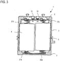
- FIG. 3 is a configuration drawing of an example of a related-art battery housing device.
- a battery housing device 1 has a case main body 2 and a cover 3.
- Batteries 4 and 5 are housed in the battery housing device 1.
- the batteries 4 and 5 are D batteries.
- the batteries 4 and 5 are connected in series as a plus pole of the battery 4 connected to a plus pole coil spring 21a and a minus pole of the battery 5 is connected to a minus pole coil spring 22a.
- the batteries 4 and 5 supply power from connector parts 12 and 13 through a circuit board 6 having a plus pole coil spring 22b connected to a plus pole of the battery 5 and a minus pole coil spring 21b connected to a minus pole of the battery 4.
- conical coil springs are used as the plus pole coil springs 21a and 22b and spring crests come in contact with convex parts of the plus poles of the batteries.
- cylindrical coil springs are used as the minus pole coil springs 22a and 21b.
- Each of the minus pole coil springs 22a and 21b has a larger inner diameter than the convex part of the plus pole of the battery so as not to come in erroneous contact with the convex part of the plus pole of the battery and comes in contact with the minus pole of the battery.
- the case main body 2 is fixed to the cover 3 with screws and the batteries 4 and 5 are housed in the battery housing device.
- the plus pole and the minus pole of each battery are pressed by the coil springs, etc., thereby fixing the battery.
- Japanese Patent Laid-Open No. 2009-27513 describes such a related-art battery housing device.
- the performance degradation is mainly caused to occur due to vibration and shock; it occurs because of destruction of a power generation element in the battery, destruction of an electric power collecting mechanism from an electrode to an external terminal.
- charging and discharging are performed in the battery, whereby an active substance of a pole plate is repeatedly expanded and shrunken; if a gap produced at the expanding time becomes a crack because of external vibration and shock and active substance for storing electricity drops, performance degradation of output voltage lowering, etc., occurs.
- the related-art battery housing device is not resistant to vibration or shock in the structure in FIG. 3 and thus there is a problem in that performance degradation of the battery such as output voltage lowering occurs.
- a structure wherein a silicone-based elastic body is placed in all or a part of places where a battery and a battery case can come in contact with each other and a buffer function between the battery and the battery case is held a structure wherein a vibration and shock absorption section for elastically abutting an end surface of an electric cell fitted into a battery holding section and absorbing vibration and shock, and the like are discussed, for example, as described in Japanese Patent Laid Open No. Hei. 11-45691 and Japanese Patent Laid Open No. 2010-40243 .
- JP62-012262U discloses a battery housing device provided with a battery support in the form of a cage into which the batteries are inserted from a lateral side.
- This cage has holes at a top and a bottom plate of the cage for pole springs and the battery is held within the cage by side wall support parts connecting the top and bottom plates.
- Exemplary embodiments of the present invention provide a battery housing device which is resistant to vibration and shock, can prevent performance degradation of a battery, and enables easy replacement of a battery.
- a battery housing device comprises:
- the battery support comprises at least one battery fixing part comprising a hole through which one of the plus pole spring or the minus pole spring is connected to the battery, and comprising a plurality of fixing members configured to be placed in a margin of the bottom face of the battery and to support the bottom face of the battery when the battery is inserted, and at least one side wall support part formed like a plate extending in the length direction of the battery, joined to one end of the battery fixing part, and configured to come in contact with the side wall of the battery and to support the battery.
- the case is configured to house two batteries in parallel
- the battery support comprises two battery fixing parts joined at one end to each other
- the side wall support part joins with a joined portion of the battery fixing parts and is formed like the plate extending in the length direction of the battery in all or a part of place where the batteries can come in contact with each other.
- the case is configured to house a plurality of batteries
- the battery support comprises a plurality of battery fixing parts and each of the battery fixing parts is joined at least at one end of another battery fixing part
- the battery support comprises a plurality of side wall support parts and each of the side wall support parts joins with at least any of the battery fixing parts in a joined portion of the battery fixing parts.
- the battery fixing part is formed of a rubber material
- the side wall support part comprises a flat plate formed of a rubber material and rigid side wall support members attached to a part or all of both faces of the flat plate.
- the case comprises a first case member wherein the battery support is disposed, the first case member comprising at least either the minus pole spring or the plus pole spring, and a second case member comprising at least either the plus pole spring or the minus pole spring.
- the battery support is inserted into the first case member, the battery is inserted into the first case member, and then the first case member and the second case member are fixed.
- the battery housing device includes the battery support for supporting the bottom face of the battery and the side wall of the battery and the battery can be attached to and detached from the battery support in the length direction of the battery, whereby the battery housing device becomes resistant to vibration and shock and can prevent performance degradation of the battery.
- the battery housing device has the wide wall support part formed by attaching the rigid member to both faces of the rubber flat plate part formed extending from the joint part of the battery fixing parts forming the battery support to space between the batteries, whereby rubber deformation at the battery inserting time is prevented and the battery can be easily inserted.
- the case of the battery housing device includes the first case member including at least either the minus pole spring or the plus pole spring wherein the battery support is disposed and the second case member including at least either the plus pole spring, or the minus pole spring, wherein after the battery support is inserted into the first case member, the battery is inserted into the first case member and then the first case member and the second case member are fixed. Therefore, the first case member and the second case member are screwed and fixed or the screw is removed and the batteries can be attached and detached in the length direction of the batteries, whereby the battery housing device is effective in that the batteries can be easily replaced without fitting an O ring into the battery periphery and without adhering and fixing the batteries to the battery case with a sealant as in the related art.
- the battery housing device of the invention is also effective in that the coil springs or the plate springs follow motion of the battery occurring at vibration acceleration not only in a stationary state, but also in a vibration state and contact can be always kept. Therefore, there can be provided the battery housing device which do not cause instantaneous interruption or a contact failure between the battery and the terminal to occur and can prevent a contact error in the vibration state.
- the plus pole of the battery is electrically insulated except for the convex part and the spring crest inner diameter of the cylindrical coil spring of the minus pole (or convex part circumventing hole formed in minus pole plate spring) is larger than the convex part of the battery plus pole.
- the battery support comprises two battery fixing parts joined at one end to each other, the side wall support part joins with the joint portion of the battery fixing parts and is formed like a plate extending in the length direction of the battery in all or a part of place where the batteries can come in contact with each other in the joint portion of the battery fixing parts, and two batteries are housed in parallel, whereby the battery housing device becomes resistant to vibration and shock and can prevent performance degradation of the battery, and rubber deformation at the battery inserting time is prevented, the battery can be easily inserted, and two batteries can be arranged and housed in parallel.
- the battery support includes a plurality of battery fixing parts, the battery fixing parts are joined at least at one end of another battery fixing part, the plurality of side wall support parts join with at least any of the battery fixing parts in the joint portion of the battery fixing parts and are formed like a plate extending in the length direction of the battery in all or a part of place where the batteries can come in contact with each other, and a plurality of batteries are housed, whereby the battery housing device becomes resistant to vibration and shock and can prevent performance degradation of the battery, and rubber deformation at the battery inserting time is prevented, the battery can be easily inserted, and a plurality of batteries can be arranged and housed in a plurality of rows.
- FIGS. 1A and 1B are configuration drawings of one embodiment of a battery housing device according to the invention.
- FIG. 2 is a schematic representation of assembly of the battery housing device in FIG. 1 . Parts common to those in FIG. 3 are denoted by the same reference numerals in FIGS. 1A and 1B and will not be discussed again as required.
- FIG. 1A is a configuration example of the battery housing device and FIG. 1B is perspective view of a battery support.
- the battery housing device of the embodiment differs from that in FIG. 3 mainly in that the battery housing device includes a battery support for clamping a bottom face of a battery and supporting side walls of the battery and that the battery can be attached to and detached from the battery support in the length direction of the battery.
- a battery housing device 100 is mainly made up of a case main body 2 of an example of a first case member, a cover 3 of an example of a second case member, and a battery support 50 for supporting bottom faces of batteries 4 and 5 and supporting side walls of the batteries 4 and 5.
- the batteries 4 and 5 are, for example, cylindrical batteries of D batteries, etc., or batteries of any other shape, etc., and are housed detachably from the battery support 50 in the length direction of the batteries.
- the case main body 2 is shaped like a box of a size that can house the batteries 4 and 5 and has an opening part for housing and taking out the batteries 4 and 5 on the top.
- the case main body 2 includes springs for fixing and electrically connecting the batteries 4 and 5, such as a plus pole coil spring 21a and a minus pole coil spring 22a on a bottom face of an inner wall.
- the case main body 2 includes a plus terminal and a minus terminal and one end of the plus pole coil spring 21a is connected to the plus terminal and one end of the minus pole coil spring 22a is connected to the minus terminal.
- the case main body 2 is formed by molding a synthetic resin, for example.
- the one end of the plus pole coil spring 21a is electrically connected to the one end of the minus pole coil spring 22a.
- the plus pole coil spring 21a and the minus pole coil spring 22a may be integrally molded using metal, etc.
- an opposite end of the plus pole coil spring 21a is electrically connected to a plus pole of the battery 4 and an opposite end of the minus pole coil spring 22a is electrically connected to a minus pole of the battery 5.
- the cover 3 is a lid part of the case main body 2 and is shaped like a box of a size that can house the batteries 4 and 5 and has an opening part for covering the batteries 4 and 5 and fitting into the case main body 2 in a lower part.
- the cover 3 includes springs for fixing and electrically connecting the batteries 4 and 5, such as a minus pole coil spring 21b and a plus pole coil spring 22b on a bottom face of an inner wall.
- the cover 3 also includes a circuit board 6 including the minus pole coil spring 21b, the plus pole coil spring 22b, and connector parts 12 and 13 for supplying power supplied from the batteries 4 and 5.
- the opposite end of the plus pole coil spring 22b is connected to a plus terminal formed on the circuit board 6 and the opposite end of the minus pole coil spring 22a is connected to a minus terminal formed on the circuit board 6.
- the cover 3 is formed by molding a synthetic resin, for example.
- the opposite end of the minus pole coil spring 21b is electrically connected to a minus pole of the battery 4 and the opposite end of the plus pole coil spring 22b is electrically connected to a plus pole of the battery 5.
- the battery support 50 is, for example, a silicone rubber molded article and is made up of a battery fixing part 51 for supporting an end part of the battery 4 (bottom face, vicinity of bottom face), a battery fixing part 52 for supporting the bottom face of the battery 5, and a side wall support part 53 for supporting side walls of the batteries 4 and 5.
- the battery support 50 clamps and fixes the bottom faces of the batteries 4 and 5 by the battery fixing parts 51 and 52 and supports the side walls of the batteries 4 and 5 by the side wall support part 53 (for example, supports the side walls so that the batteries do not come in contact with each other).
- the battery fixing part 51 is formed as a shape similar to the bottom face of the battery 4 or a shape of a larger size than the bottom face of the battery 4 and includes a plurality of fixing members 51a, 51b, and 51c placed in a margin of the bottom (peripheral margin, etc.,) of the battery 4 for supporting the bottom face of the battery 4 when the battery is inserted and a hole 51h of a shape larger than the connection portion of the spring (plus pole coil spring 21a) and the battery 4.
- the battery fixing part 52 is formed as a shape similar to the bottom face of the battery 5 or a shape of a larger size than the bottom face of the battery 5 and includes a plurality of fixing members 52a, 52b, and 52c placed in a margin of the bottom (peripheral margin, etc.,) of the battery 5 for clamping the bottom face of the battery 5 when the battery is inserted and a hole 52h of a shape larger than the connection portion of the spring (minus pole coil spring 22a) and the battery 5.
- the battery fixing parts 51 and 52 press and support the battery in the length direction (axial direction of the battery) from the battery bottom face.
- the battery is clamped in the axial direction of the battery by the battery fixing part placed in the battery bottom part and the spring.
- the fixing members 52a, 52b, and 52c of the battery fixing part 52 may press and clamp the battery in the radius direction (toward the axis of the battery) or may simply support the battery to fix the position of the bottom face of the battery 5.
- the fixing members 51a, 51b, and 51c of the battery fixing part 51 may press and clamp the battery 4 in the radius direction of the bottom face of the battery 4 (toward the axis of the battery) or may simply support the battery.
- the battery fixing parts 51 and 52 are not limited to silicone rubber molded article and may be formed of any other rubber material.
- any number of the fixing members may be formed in the margins of the battery fixing parts 51 and 52 if they clamp the bottom parts of the batteries 4 and 5.
- the battery fixing parts 51 and 52 are joined at one end.
- the rubber flat plate part GB is formed like a flat plate extending in the perpendicular direction on the faces of the battery fixing parts 51 and 52 and is formed between the batteries 4 and 5 at the battery insertion time.
- the side wall support part 53 is a polycarbonate (PC sheet) component, is joined to one end of the battery fixing parts 51 and 52, is formed like a plate extending in the length direction of the battery 4, 5, and comes in contact with the side wall of the battery 4, 5 for supporting the battery 4, 5.
- PC sheet polycarbonate
- the side wall support part 53 is formed by attaching side wall support members 53a and 53b of rigid PC sheet components to both faces of the rubber flat plate part GB formed between the batteries 4 and 5 of the battery fixing parts 51 and 52.
- the side wall support members 53a and 53b of the side wall support part 53 come in contact with the side walls of the batteries 4 and 5 (for example, a part of an outer peripheral surface) for supporting the batteries 4 and 5.
- the side wall support part 53 is not limited to a PC sheet component and may be formed of any other resin or metal.
- a gap needs to be provided between the battery and the cover and between the battery and the case main body because there are variations in the sizes of the batteries 4 and 5 and the shapes of the cover 3 and the case main body 2.
- the battery fixing parts 51 and 52 have a buffer function of eliminating the gap between the battery 4, 5 and the cover 3 and the gap between the battery 4, 5 and the case main body 2 while fixing the batteries.
- the battery housing device 100 of the invention is resistant to vibration and shock and can prevent performance degradation of the batteries as the battery fixing parts 51 and 52 press (support) the batteries in the length direction from the bottom faces of the batteries.
- the battery fixing parts 51 and 52 support the batteries 4 and 5 and serve the buffer function, but are molded of silicone rubber or any other rubber material and thus have no rigidity. Thus, when the batteries 4 and 5 are inserted into the case main body 2, if the rubber flat plate part GB formed extending between the batteries 4 and 5 from the joint portion of the battery fixing parts 51 and 52 exists only, the rubber flat plate part GB may become deformed.
- the rubber flat plate part GB is pushed in together with the batteries 4 and 5 and the battery fixing parts 51 and 52 cannot be placed at the essential position or the rubber flat plate part GB formed between the batteries 4 and 5 is crammed into the back and the batteries 4 and 5 cannot be inserted.
- the battery housing device 100 of the invention has the side wall support part 53 provided by attaching the side wall support members 53a and 53b of rigid plate-like PC sheet components to all or a part of both faces of the rubber flat plate part GB formed extending between the batteries 4 and 5 from the joint portion of the battery fixing parts 51 and 52 of silicone rubber molded articles, thereby preventing rubber deformation when the batteries 4 and 5 are inserted and enabling the user to easily insert the batteries.
- the degree of the rigidity of the side wall support part 53 is not limited and the side wall support part 53 may be able to become deformed conforming to the rubber flat plate part GB.
- the battery housing device 100 of the invention includes the side wall support part 53 having rigidity, whereby the batteries 4 and 5 can be supported in the length direction of the batteries in a state in which the battery fixing parts 51 and 52 (rubber) and the rubber flat plate part GB are placed at the essential positions (in a state in which deformation of the rubber flat plate part GB does not occur). Further, the rubber flat plate part GB supports a part of the outer peripheral surface of the battery in the width direction of the battery (presses in the radius direction of the battery, the battery side wall direction), whereby the battery housing device 100 becomes resistant to vibration and shock and can prevent performance degradation.
- FIG. 2 An example of an assembling method of the battery housing device in FIG. 1 will be discussed with FIG. 2 .
- the battery support 50 with the side wall support part 53 attached to one ends of the battery fixing parts 51 and 52 is assembled and fixed to the case main body 2 to which the plus pole coil spring 21a and the minus pole coil spring 22a are attached.
- the batteries 4 and 5 are inserted into the case main body 2 from the length direction of the batteries and are attached to the battery support 50. At this time, the fixing members 51a to 51c and 52a to 52c of the battery fixing parts 51 and 52 of the battery support 50 clamp the bottom parts of the batteries 4 and 5 and the side wall support members 53a and 53b of the side wall support part 53 of the battery support 50 support the side walls of the batteries 4 and 5.
- the cover 3 is placed so as to cover the batteries 4 and 5 and is fixed to the case main body 2 with a screw.
- the plus pole of the battery 4 is connected to the plus pole coil spring 21a through the hole 51h of the battery fixing part 51.
- the minus pole of the battery 5 is connected to the minus pole coil spring 22a through the hole 52h of the battery fixing part 52.
- the plus pole of the battery 4 is connected to the plus pole coil spring 21a and the minus pole of the battery 5 is connected to the minus pole coil spring 22a, whereby the batteries 4 and 5 are connected in series via the springs 21a and 22a.
- the batteries 4 and 5 supply power from the connector parts 12 and 13 through the circuit board 6 including the minus pole coil spring 21b and the plus pole coil spring 22b.
- the coil springs 21a, 21b, 22a, and 22b are used as members electrically connected to the plus poles and the minus poles of the batteries, but the embodiment is not limited to the mode.
- Plate springs 31a, 31b, 32a and 32b may be used in place of the coil springs 21a, 21b, 22a, and 22b.
- the batteries 4 and 5 are connected in series via the plus pole plate spring 31a and the minus pole plate spring 32a and supply power from the connector parts 12 and 13 through the circuit board 6 including the minus pole coil spring 31b and the plus pole coil spring 32b.
- Each of the minus pole plate springs 32a and 31b is formed with a convex part circumventing hole having a larger diameter than a convex part of the plus pole of the battery 4, 5 so that erroneous contact with the convex part can be circumvented.
- the plus pole plate spring 31a and the minus pole plate spring 32a may be formed in one body.
- the battery fixing parts 51 and 52 press (support) batteries in the length direction of the batteries and further the side wall support part 53 supports a part of the outer peripheral surface of the battery in the width direction of the battery (presses in the radius direction of the battery, the battery side wall direction), whereby the battery housing device of the invention becomes resistant to vibration and shock and can prevent performance degradation of the batteries.
- the battery housing device of the invention has the side wall support part 53 with the rigid side wall support members 53a and 53b attached to both faces of the rubber flat plate part GB formed extending between the batteries 4 and 5 from the joint portion of the battery fixing parts 51 and 52, whereby rubber deformation at the inserting time of the batteries 4 and 5 can be prevented and the batteries can be easily inserted.
- the case main body 2 and the cover 3 are screwed and fixed or the screw is removed and batteries 4 and 5 can be attached and detached in the length direction of the batteries, whereby the battery housing device of the invention is effective in that the batteries can be easily replaced without fitting an O ring into the battery periphery and without adhering and fixing the batteries to the battery case with a sealant as in the related art.
- coil springs or plate springs are adopted as terminals on both pole sides of the battery, whereby the battery housing device of the invention is also effective in that the coil springs or the plate springs follow motion of the battery occurring at vibration acceleration not only in a stationary state, but also in a vibration state and contact can be always kept.
- the battery housing device which do not cause instantaneous interruption or a contact failure between the battery and the terminal to occur and can prevent a contact error in the vibration state.
- the plus pole of the battery is electrically insulated except for the convex part and the spring crest inner diameter of the cylindrical coil spring of the minus pole (or convex part circumventing hole formed in minus pole plate spring) is larger than the convex part of the battery plus pole and thus contact with the convex part (energization) does not occur.
- the two batteries 4 and 5 are housed, but the number of housed batteries is not limited to two and a battery housing device wherein one or more batteries are housed in parallel may be adopted.
- a battery support 50 includes a battery fixing part 51 and a side wall support part 53 joined to one end of the battery fixing part 51 and side wall support part 53 is formed like a plate extending in the length direction of the battery and comes in contact with a side wall of the battery for supporting the battery (not shown).
- the battery support 50 includes a plurality of battery fixing parts (three battery fixing parts 51, 52, and 54 (not shown)) and a plurality of side wall support parts 53 and 55 (not shown).
- the battery fixing parts 51, 52, and 54 are arranged in a row and are joined at one end of another battery fixing part.
- the side wall support part 53 is formed like a plate extending in the length direction of the battery in all or a part of place where the batteries can come in contact with each other in the joint portion of the battery fixing parts 51 and 52.
- the side wall support part 55 is formed like a plate extending in the length direction of the battery in all or a part of place where the batteries can come in contact with each other in the joint portion of the battery fixing parts 52 and 54.
- a plurality of battery fixing parts are arranged in a row, a plurality of side wall support parts are placed in all or a part of the joint portion of the battery fixing parts where the batteries can come in contact with each other, and further the battery fixing parts 51 and 52 press (support) batteries in the length direction of the batteries and further the side wall support part supports a part of the outer peripheral surface of the battery in the width direction of the battery (presses in the radius direction of the battery, the battery side wall direction), whereby the battery housing device of the invention becomes resistant to vibration and shock, can prevent performance degradation of the batteries, prevents rubber deformation at the battery insertion time, enables easily battery insertion, and can house a plurality of batteries in parallel.
- a case main body and a cover are screwed and fixed or the screw is removed and the batteries can be attached and detached in the length direction of the batteries, whereby the battery housing device of the invention is effective in that the batteries can be easily replaced.
- the two batteries 4 and 5 are housed in a row in parallel, but the invention is not limited to the mode.
- a battery housing device wherein a plurality of batteries are arranged in a plurality of rows may be adopted.
- a battery support 50 includes a plurality of battery fixing parts (four battery fixing parts 51, 52, 54, and 56 (not shown)) and a plurality of side wall support parts 53, 55, 57, and 58 (not shown).
- the battery fixing parts 51, 52, 54, and 56 are arranged in two rows of a row of the battery fixing parts 51 and 52 and a row of the battery fixing parts 54 and 56.
- the battery fixing parts 51, 52, 54, and 56 are joined at least at one end of another battery fixing part.
- the side wall support part 53 is formed like a plate extending in the length direction of the battery in all or a part of the joint portion of the battery fixing parts 51 and 52 where the batteries can come in contact with each other.
- the side wall support part 55 is formed like a plate extending in the length direction of the battery in all or a part of the joint portion of the battery fixing parts 54 and 56 where the batteries can come in contact with each other.
- the side wall support part 57 is formed like a plate extending in the length direction of the battery in all or a part of the joint portion of the battery fixing parts 51 and 54 where the batteries can come in contact with each other.
- the side wall support part 58 is formed like a plate extending in the length direction of the battery in all or a part of the joint portion of the battery fixing parts 52 and 56 where the batteries can come in contact with each other.
- the battery housing device of the invention has the battery support with a plurality of battery fixing parts arranged in a plurality of rows and a plurality of side wall support parts installed in all or a part of the place where the batteries can come in contact with each other, whereby the battery housing device becomes resistant to vibration and shock, can prevent performance degradation of the batteries, prevents rubber deformation at the battery insertion time, enables easily battery insertion, and can house a plurality of batteries arranged in a plurality of rows.
- a case main body and a cover are screwed and fixed or the screw is removed and the batteries can be attached and detached in the length direction of the batteries, whereby the battery housing device of the invention is effective in that the batteries can be easily replaced.
- a battery fixing part may be further placed in a cover 3 and a top face of a battery may be clamped for fixing the battery. Accordingly, the battery housing device becomes resistant to vibration and shock and can prevent performance degradation of the batteries.
Landscapes
- Chemical & Material Sciences (AREA)
- Chemical Kinetics & Catalysis (AREA)
- Electrochemistry (AREA)
- General Chemical & Material Sciences (AREA)
- Battery Mounting, Suspending (AREA)
- Connection Of Batteries Or Terminals (AREA)
Applications Claiming Priority (1)
| Application Number | Priority Date | Filing Date | Title |
|---|---|---|---|
| JP2010120611A JP5177176B2 (ja) | 2010-05-26 | 2010-05-26 | 電池収納装置 |
Publications (2)
| Publication Number | Publication Date |
|---|---|
| EP2390943A1 EP2390943A1 (en) | 2011-11-30 |
| EP2390943B1 true EP2390943B1 (en) | 2019-09-25 |
Family
ID=44343798
Family Applications (1)
| Application Number | Title | Priority Date | Filing Date |
|---|---|---|---|
| EP11167028.7A Active EP2390943B1 (en) | 2010-05-26 | 2011-05-23 | Battery housing device |
Country Status (5)
| Country | Link |
|---|---|
| US (1) | US9048481B2 (es) |
| EP (1) | EP2390943B1 (es) |
| JP (1) | JP5177176B2 (es) |
| CN (1) | CN102263215B (es) |
| ES (1) | ES2762178T3 (es) |
Families Citing this family (22)
| Publication number | Priority date | Publication date | Assignee | Title |
|---|---|---|---|---|
| JP5492756B2 (ja) * | 2010-12-07 | 2014-05-14 | 株式会社増田屋ホールディングス | 玩具用乾電池ボックス |
| JP5597156B2 (ja) * | 2011-03-29 | 2014-10-01 | アズビル株式会社 | フィールド機器 |
| JP2013168321A (ja) * | 2012-02-16 | 2013-08-29 | Mitsubishi Heavy Ind Ltd | 電池モジュール |
| CN103137923B (zh) * | 2013-03-13 | 2015-05-13 | 宁波超霸能源有限公司 | 一种6v锂电池 |
| CN103137924B (zh) * | 2013-03-13 | 2015-05-13 | 宁波超霸能源有限公司 | 一种3v锂电池 |
| USD722953S1 (en) * | 2013-05-15 | 2015-02-24 | Samsung Electronics Co., Ltd. | Battery for digital camera |
| JP6183007B2 (ja) * | 2013-07-01 | 2017-08-23 | 日本ケミコン株式会社 | コンデンサモジュールおよびその製造方法 |
| DE102013111146A1 (de) | 2013-10-09 | 2015-04-09 | Dr. Ing. H.C. F. Porsche Aktiengesellschaft | Batteriemodul für ein Kraftfahrzeug |
| CN103579549A (zh) * | 2013-10-25 | 2014-02-12 | 昆山市大久电子有限公司 | 一种带有散热装置的电池盒 |
| USD719095S1 (en) * | 2013-10-25 | 2014-12-09 | Yokogawa Electric Corporation | Battery case |
| CN105705408A (zh) * | 2013-11-06 | 2016-06-22 | 雅马哈发动机株式会社 | 骑乘式电动车 |
| CN103579550B (zh) * | 2013-11-23 | 2015-08-19 | 清华大学 | 油气管道缺陷内检测器电池包单元 |
| EP3085499A1 (de) * | 2015-04-24 | 2016-10-26 | HILTI Aktiengesellschaft | Werkzeugakku-schutzschale |
| USD759592S1 (en) * | 2015-06-30 | 2016-06-21 | Flir Surveillance, Inc. | Battery pack lid |
| CN106910862A (zh) * | 2017-02-28 | 2017-06-30 | 长沙安靠电源有限公司 | 插入式电池连接装置 |
| CN107994145B (zh) * | 2017-11-20 | 2021-09-24 | 肇庆中特能科技投资有限公司 | 密封抗震蓄电池及其制备方法 |
| KR102311075B1 (ko) * | 2018-04-09 | 2021-10-07 | 주식회사 엘지에너지솔루션 | 팩 하우징을 포함하는 배터리 팩 |
| DE102018208342A1 (de) * | 2018-05-28 | 2019-11-28 | Robert Bosch Gmbh | Gehäuse für ein Batteriemodul und Batteriemodul |
| CN109346632B (zh) * | 2018-09-21 | 2021-04-06 | 浙江零跑科技有限公司 | 浸入式涂胶支架及组装方法 |
| KR102170309B1 (ko) * | 2019-12-06 | 2020-10-26 | 숭실대학교산학협력단 | 고효율 무선 헤어드라이어 |
| KR102321969B1 (ko) * | 2020-03-04 | 2021-11-04 | (주)엠피에스코리아 | 일체형 스프링 전극단자를 구비한 리튬전지 배터리 팩 구조 |
| WO2022047056A1 (en) * | 2020-08-27 | 2022-03-03 | Tarter Cody J | Document display holder for motor vehicles |
Family Cites Families (19)
| Publication number | Priority date | Publication date | Assignee | Title |
|---|---|---|---|---|
| DE1138442B (de) * | 1958-11-17 | 1962-10-25 | Siemens Ag | Gehaeuse fuer Batterien fuer Fernmeldeanlagen, insbesondere fuer tragbare Stationen in Fernsprechanlagen |
| JPS567264U (es) * | 1979-06-29 | 1981-01-22 | ||
| JPS5564274U (es) * | 1979-11-05 | 1980-05-01 | ||
| JPS6028050Y2 (ja) * | 1981-05-20 | 1985-08-24 | 新神戸電機株式会社 | 電池ケ−ス |
| JPS6212262U (es) | 1985-07-05 | 1987-01-24 | ||
| US4772948A (en) | 1987-10-26 | 1988-09-20 | Tektronix, Inc. | Method of low cost self-test in a video display system system |
| JPH02110170U (es) * | 1989-02-20 | 1990-09-04 | ||
| JP2746143B2 (ja) * | 1994-09-29 | 1998-04-28 | ミノルタ株式会社 | 電池収納ケース及びケース収納電池 |
| GB9502243D0 (en) | 1995-02-06 | 1995-03-29 | Radiodetection Ltd | Battery housing |
| JPH1145691A (ja) | 1997-07-28 | 1999-02-16 | Shin Kobe Electric Mach Co Ltd | 電池パック |
| JPH11126592A (ja) * | 1997-10-23 | 1999-05-11 | Taiyodo:Kk | 電池のカセットケース |
| JP2001210290A (ja) | 2000-01-31 | 2001-08-03 | Tookado:Kk | 電池パック |
| JP2004199957A (ja) | 2002-12-17 | 2004-07-15 | Sharp Corp | 電池収容装置 |
| CN2629228Y (zh) * | 2003-06-20 | 2004-07-28 | 顺德市顺达电脑厂有限公司 | 电池座 |
| US7491466B2 (en) * | 2005-06-03 | 2009-02-17 | Eveready Battery Company, Inc. | Battery with side terminal |
| JP4981522B2 (ja) * | 2007-05-28 | 2012-07-25 | 本多通信工業株式会社 | 電池ボックス |
| TWM343927U (en) * | 2008-03-19 | 2008-11-01 | Wistron Corp | Fastening device and portable electronic device |
| JP5477613B2 (ja) * | 2008-05-15 | 2014-04-23 | 横河電機株式会社 | 電池収納装置 |
| JP2010040243A (ja) | 2008-08-01 | 2010-02-18 | Panasonic Corp | 電池モジュール |
-
2010
- 2010-05-26 JP JP2010120611A patent/JP5177176B2/ja active Active
-
2011
- 2011-05-20 US US13/112,686 patent/US9048481B2/en active Active
- 2011-05-23 EP EP11167028.7A patent/EP2390943B1/en active Active
- 2011-05-23 ES ES11167028T patent/ES2762178T3/es active Active
- 2011-05-26 CN CN201110138463.0A patent/CN102263215B/zh not_active Expired - Fee Related
Non-Patent Citations (1)
| Title |
|---|
| None * |
Also Published As
| Publication number | Publication date |
|---|---|
| CN102263215A (zh) | 2011-11-30 |
| JP2011249114A (ja) | 2011-12-08 |
| JP5177176B2 (ja) | 2013-04-03 |
| US20110293979A1 (en) | 2011-12-01 |
| EP2390943A1 (en) | 2011-11-30 |
| US9048481B2 (en) | 2015-06-02 |
| ES2762178T3 (es) | 2020-05-22 |
| CN102263215B (zh) | 2014-06-04 |
Similar Documents
| Publication | Publication Date | Title |
|---|---|---|
| EP2390943B1 (en) | Battery housing device | |
| KR102826299B1 (ko) | 배터리 셀 홀더 및 배터리 시스템 | |
| CN102064333B (zh) | 电池 | |
| EP2381507B1 (en) | Battery pack | |
| KR100872954B1 (ko) | 전원 장치 | |
| CN108028332B (zh) | 蓄电装置 | |
| EP2704230B1 (en) | Battery assembly, and vehicle | |
| US11088388B2 (en) | Clamping member and battery module using the same | |
| EP2897193B1 (en) | Rechargeable battery pack | |
| KR101547395B1 (ko) | 전지모듈 하우징 | |
| JP5625294B2 (ja) | 電池モジュール | |
| CA2593944A1 (en) | Fuel cell stack | |
| KR102019884B1 (ko) | 배터리 모듈 및 이러한 배터리 모듈을 포함하는 배터리 팩 및 이러한 배터리 팩을 포함하는 자동차 | |
| US20190081292A1 (en) | Battery pack | |
| EP3485523A1 (en) | Battery holder | |
| KR102735368B1 (ko) | 배터리 유닛, 피드스루 어셈블리 및 전자 장치 | |
| JP6613773B2 (ja) | 蓄電装置 | |
| WO2024005034A1 (ja) | 蓄電モジュール | |
| EP4459762A1 (en) | Electricity storage pack | |
| CN114284616B (zh) | 免焊接电池模组 | |
| JP2018063862A (ja) | 車載用電池モジュール | |
| KR101201813B1 (ko) | 전지 모듈 | |
| EP3518319A1 (en) | Battery pack and electrically conductive member | |
| CN215644906U (zh) | 电池包 | |
| JP2019153518A (ja) | 電気機器 |
Legal Events
| Date | Code | Title | Description |
|---|---|---|---|
| AK | Designated contracting states |
Kind code of ref document: A1 Designated state(s): AL AT BE BG CH CY CZ DE DK EE ES FI FR GB GR HR HU IE IS IT LI LT LU LV MC MK MT NL NO PL PT RO RS SE SI SK SM TR |
|
| AX | Request for extension of the european patent |
Extension state: BA ME |
|
| PUAI | Public reference made under article 153(3) epc to a published international application that has entered the european phase |
Free format text: ORIGINAL CODE: 0009012 |
|
| 17P | Request for examination filed |
Effective date: 20120326 |
|
| 17Q | First examination report despatched |
Effective date: 20140206 |
|
| STAA | Information on the status of an ep patent application or granted ep patent |
Free format text: STATUS: EXAMINATION IS IN PROGRESS |
|
| GRAP | Despatch of communication of intention to grant a patent |
Free format text: ORIGINAL CODE: EPIDOSNIGR1 |
|
| STAA | Information on the status of an ep patent application or granted ep patent |
Free format text: STATUS: GRANT OF PATENT IS INTENDED |
|
| INTG | Intention to grant announced |
Effective date: 20190412 |
|
| GRAS | Grant fee paid |
Free format text: ORIGINAL CODE: EPIDOSNIGR3 |
|
| GRAA | (expected) grant |
Free format text: ORIGINAL CODE: 0009210 |
|
| STAA | Information on the status of an ep patent application or granted ep patent |
Free format text: STATUS: THE PATENT HAS BEEN GRANTED |
|
| AK | Designated contracting states |
Kind code of ref document: B1 Designated state(s): AL AT BE BG CH CY CZ DE DK EE ES FI FR GB GR HR HU IE IS IT LI LT LU LV MC MK MT NL NO PL PT RO RS SE SI SK SM TR |
|
| REG | Reference to a national code |
Ref country code: GB Ref legal event code: FG4D |
|
| REG | Reference to a national code |
Ref country code: CH Ref legal event code: EP |
|
| REG | Reference to a national code |
Ref country code: AT Ref legal event code: REF Ref document number: 1184710 Country of ref document: AT Kind code of ref document: T Effective date: 20191015 |
|
| REG | Reference to a national code |
Ref country code: IE Ref legal event code: FG4D |
|
| REG | Reference to a national code |
Ref country code: DE Ref legal event code: R096 Ref document number: 602011062270 Country of ref document: DE |
|
| REG | Reference to a national code |
Ref country code: NO Ref legal event code: T2 Effective date: 20190925 |
|
| REG | Reference to a national code |
Ref country code: NL Ref legal event code: FP |
|
| PG25 | Lapsed in a contracting state [announced via postgrant information from national office to epo] |
Ref country code: BG Free format text: LAPSE BECAUSE OF FAILURE TO SUBMIT A TRANSLATION OF THE DESCRIPTION OR TO PAY THE FEE WITHIN THE PRESCRIBED TIME-LIMIT Effective date: 20191225 Ref country code: HR Free format text: LAPSE BECAUSE OF FAILURE TO SUBMIT A TRANSLATION OF THE DESCRIPTION OR TO PAY THE FEE WITHIN THE PRESCRIBED TIME-LIMIT Effective date: 20190925 Ref country code: SE Free format text: LAPSE BECAUSE OF FAILURE TO SUBMIT A TRANSLATION OF THE DESCRIPTION OR TO PAY THE FEE WITHIN THE PRESCRIBED TIME-LIMIT Effective date: 20190925 Ref country code: FI Free format text: LAPSE BECAUSE OF FAILURE TO SUBMIT A TRANSLATION OF THE DESCRIPTION OR TO PAY THE FEE WITHIN THE PRESCRIBED TIME-LIMIT Effective date: 20190925 Ref country code: LT Free format text: LAPSE BECAUSE OF FAILURE TO SUBMIT A TRANSLATION OF THE DESCRIPTION OR TO PAY THE FEE WITHIN THE PRESCRIBED TIME-LIMIT Effective date: 20190925 |
|
| REG | Reference to a national code |
Ref country code: LT Ref legal event code: MG4D |
|
| PG25 | Lapsed in a contracting state [announced via postgrant information from national office to epo] |
Ref country code: GR Free format text: LAPSE BECAUSE OF FAILURE TO SUBMIT A TRANSLATION OF THE DESCRIPTION OR TO PAY THE FEE WITHIN THE PRESCRIBED TIME-LIMIT Effective date: 20191226 Ref country code: LV Free format text: LAPSE BECAUSE OF FAILURE TO SUBMIT A TRANSLATION OF THE DESCRIPTION OR TO PAY THE FEE WITHIN THE PRESCRIBED TIME-LIMIT Effective date: 20190925 Ref country code: RS Free format text: LAPSE BECAUSE OF FAILURE TO SUBMIT A TRANSLATION OF THE DESCRIPTION OR TO PAY THE FEE WITHIN THE PRESCRIBED TIME-LIMIT Effective date: 20190925 |
|
| REG | Reference to a national code |
Ref country code: AT Ref legal event code: MK05 Ref document number: 1184710 Country of ref document: AT Kind code of ref document: T Effective date: 20190925 |
|
| PG25 | Lapsed in a contracting state [announced via postgrant information from national office to epo] |
Ref country code: AL Free format text: LAPSE BECAUSE OF FAILURE TO SUBMIT A TRANSLATION OF THE DESCRIPTION OR TO PAY THE FEE WITHIN THE PRESCRIBED TIME-LIMIT Effective date: 20190925 Ref country code: RO Free format text: LAPSE BECAUSE OF FAILURE TO SUBMIT A TRANSLATION OF THE DESCRIPTION OR TO PAY THE FEE WITHIN THE PRESCRIBED TIME-LIMIT Effective date: 20190925 Ref country code: PL Free format text: LAPSE BECAUSE OF FAILURE TO SUBMIT A TRANSLATION OF THE DESCRIPTION OR TO PAY THE FEE WITHIN THE PRESCRIBED TIME-LIMIT Effective date: 20190925 Ref country code: PT Free format text: LAPSE BECAUSE OF FAILURE TO SUBMIT A TRANSLATION OF THE DESCRIPTION OR TO PAY THE FEE WITHIN THE PRESCRIBED TIME-LIMIT Effective date: 20200127 Ref country code: EE Free format text: LAPSE BECAUSE OF FAILURE TO SUBMIT A TRANSLATION OF THE DESCRIPTION OR TO PAY THE FEE WITHIN THE PRESCRIBED TIME-LIMIT Effective date: 20190925 Ref country code: AT Free format text: LAPSE BECAUSE OF FAILURE TO SUBMIT A TRANSLATION OF THE DESCRIPTION OR TO PAY THE FEE WITHIN THE PRESCRIBED TIME-LIMIT Effective date: 20190925 |
|
| REG | Reference to a national code |
Ref country code: ES Ref legal event code: FG2A Ref document number: 2762178 Country of ref document: ES Kind code of ref document: T3 Effective date: 20200522 |
|
| PG25 | Lapsed in a contracting state [announced via postgrant information from national office to epo] |
Ref country code: SM Free format text: LAPSE BECAUSE OF FAILURE TO SUBMIT A TRANSLATION OF THE DESCRIPTION OR TO PAY THE FEE WITHIN THE PRESCRIBED TIME-LIMIT Effective date: 20190925 Ref country code: SK Free format text: LAPSE BECAUSE OF FAILURE TO SUBMIT A TRANSLATION OF THE DESCRIPTION OR TO PAY THE FEE WITHIN THE PRESCRIBED TIME-LIMIT Effective date: 20190925 Ref country code: CZ Free format text: LAPSE BECAUSE OF FAILURE TO SUBMIT A TRANSLATION OF THE DESCRIPTION OR TO PAY THE FEE WITHIN THE PRESCRIBED TIME-LIMIT Effective date: 20190925 Ref country code: IS Free format text: LAPSE BECAUSE OF FAILURE TO SUBMIT A TRANSLATION OF THE DESCRIPTION OR TO PAY THE FEE WITHIN THE PRESCRIBED TIME-LIMIT Effective date: 20200224 |
|
| REG | Reference to a national code |
Ref country code: DE Ref legal event code: R097 Ref document number: 602011062270 Country of ref document: DE |
|
| PG2D | Information on lapse in contracting state deleted |
Ref country code: IS |
|
| PG25 | Lapsed in a contracting state [announced via postgrant information from national office to epo] |
Ref country code: DK Free format text: LAPSE BECAUSE OF FAILURE TO SUBMIT A TRANSLATION OF THE DESCRIPTION OR TO PAY THE FEE WITHIN THE PRESCRIBED TIME-LIMIT Effective date: 20190925 Ref country code: IS Free format text: LAPSE BECAUSE OF FAILURE TO SUBMIT A TRANSLATION OF THE DESCRIPTION OR TO PAY THE FEE WITHIN THE PRESCRIBED TIME-LIMIT Effective date: 20200126 |
|
| PLBE | No opposition filed within time limit |
Free format text: ORIGINAL CODE: 0009261 |
|
| STAA | Information on the status of an ep patent application or granted ep patent |
Free format text: STATUS: NO OPPOSITION FILED WITHIN TIME LIMIT |
|
| 26N | No opposition filed |
Effective date: 20200626 |
|
| REG | Reference to a national code |
Ref country code: DE Ref legal event code: R079 Ref document number: 602011062270 Country of ref document: DE Free format text: PREVIOUS MAIN CLASS: H01M0002100000 Ipc: H01M0050200000 |
|
| PG25 | Lapsed in a contracting state [announced via postgrant information from national office to epo] |
Ref country code: SI Free format text: LAPSE BECAUSE OF FAILURE TO SUBMIT A TRANSLATION OF THE DESCRIPTION OR TO PAY THE FEE WITHIN THE PRESCRIBED TIME-LIMIT Effective date: 20190925 |
|
| PG25 | Lapsed in a contracting state [announced via postgrant information from national office to epo] |
Ref country code: MC Free format text: LAPSE BECAUSE OF FAILURE TO SUBMIT A TRANSLATION OF THE DESCRIPTION OR TO PAY THE FEE WITHIN THE PRESCRIBED TIME-LIMIT Effective date: 20190925 Ref country code: CH Free format text: LAPSE BECAUSE OF NON-PAYMENT OF DUE FEES Effective date: 20200531 Ref country code: LI Free format text: LAPSE BECAUSE OF NON-PAYMENT OF DUE FEES Effective date: 20200531 |
|
| REG | Reference to a national code |
Ref country code: BE Ref legal event code: MM Effective date: 20200531 |
|
| PG25 | Lapsed in a contracting state [announced via postgrant information from national office to epo] |
Ref country code: LU Free format text: LAPSE BECAUSE OF NON-PAYMENT OF DUE FEES Effective date: 20200523 |
|
| PG25 | Lapsed in a contracting state [announced via postgrant information from national office to epo] |
Ref country code: IE Free format text: LAPSE BECAUSE OF NON-PAYMENT OF DUE FEES Effective date: 20200523 |
|
| PG25 | Lapsed in a contracting state [announced via postgrant information from national office to epo] |
Ref country code: BE Free format text: LAPSE BECAUSE OF NON-PAYMENT OF DUE FEES Effective date: 20200531 |
|
| PG25 | Lapsed in a contracting state [announced via postgrant information from national office to epo] |
Ref country code: TR Free format text: LAPSE BECAUSE OF FAILURE TO SUBMIT A TRANSLATION OF THE DESCRIPTION OR TO PAY THE FEE WITHIN THE PRESCRIBED TIME-LIMIT Effective date: 20190925 Ref country code: MT Free format text: LAPSE BECAUSE OF FAILURE TO SUBMIT A TRANSLATION OF THE DESCRIPTION OR TO PAY THE FEE WITHIN THE PRESCRIBED TIME-LIMIT Effective date: 20190925 Ref country code: CY Free format text: LAPSE BECAUSE OF FAILURE TO SUBMIT A TRANSLATION OF THE DESCRIPTION OR TO PAY THE FEE WITHIN THE PRESCRIBED TIME-LIMIT Effective date: 20190925 |
|
| PG25 | Lapsed in a contracting state [announced via postgrant information from national office to epo] |
Ref country code: MK Free format text: LAPSE BECAUSE OF FAILURE TO SUBMIT A TRANSLATION OF THE DESCRIPTION OR TO PAY THE FEE WITHIN THE PRESCRIBED TIME-LIMIT Effective date: 20190925 |
|
| REG | Reference to a national code |
Ref country code: FR Ref legal event code: PLFP Year of fee payment: 13 |
|
| PGFP | Annual fee paid to national office [announced via postgrant information from national office to epo] |
Ref country code: GB Payment date: 20230330 Year of fee payment: 13 |
|
| PGFP | Annual fee paid to national office [announced via postgrant information from national office to epo] |
Ref country code: NL Payment date: 20230417 Year of fee payment: 13 |
|
| P01 | Opt-out of the competence of the unified patent court (upc) registered |
Effective date: 20230603 |
|
| PGFP | Annual fee paid to national office [announced via postgrant information from national office to epo] |
Ref country code: NO Payment date: 20230510 Year of fee payment: 13 Ref country code: IT Payment date: 20230412 Year of fee payment: 13 Ref country code: FR Payment date: 20230411 Year of fee payment: 13 Ref country code: ES Payment date: 20230601 Year of fee payment: 13 Ref country code: DE Payment date: 20230331 Year of fee payment: 13 |
|
| REG | Reference to a national code |
Ref country code: DE Ref legal event code: R119 Ref document number: 602011062270 Country of ref document: DE |
|
| REG | Reference to a national code |
Ref country code: NL Ref legal event code: MM Effective date: 20240601 |
|
| PG25 | Lapsed in a contracting state [announced via postgrant information from national office to epo] |
Ref country code: NO Free format text: LAPSE BECAUSE OF NON-PAYMENT OF DUE FEES Effective date: 20240531 |
|
| GBPC | Gb: european patent ceased through non-payment of renewal fee |
Effective date: 20240523 |
|
| PG25 | Lapsed in a contracting state [announced via postgrant information from national office to epo] |
Ref country code: NO Free format text: LAPSE BECAUSE OF NON-PAYMENT OF DUE FEES Effective date: 20240531 |
|
| PG25 | Lapsed in a contracting state [announced via postgrant information from national office to epo] |
Ref country code: NL Free format text: LAPSE BECAUSE OF NON-PAYMENT OF DUE FEES Effective date: 20240601 |
|
| PG25 | Lapsed in a contracting state [announced via postgrant information from national office to epo] |
Ref country code: DE Free format text: LAPSE BECAUSE OF NON-PAYMENT OF DUE FEES Effective date: 20241203 |
|
| PG25 | Lapsed in a contracting state [announced via postgrant information from national office to epo] |
Ref country code: FR Free format text: LAPSE BECAUSE OF NON-PAYMENT OF DUE FEES Effective date: 20240531 |
|
| PG25 | Lapsed in a contracting state [announced via postgrant information from national office to epo] |
Ref country code: GB Free format text: LAPSE BECAUSE OF NON-PAYMENT OF DUE FEES Effective date: 20240523 Ref country code: IT Free format text: LAPSE BECAUSE OF NON-PAYMENT OF DUE FEES Effective date: 20240523 |
|
| REG | Reference to a national code |
Ref country code: ES Ref legal event code: FD2A Effective date: 20250703 |
|
| PG25 | Lapsed in a contracting state [announced via postgrant information from national office to epo] |
Ref country code: ES Free format text: LAPSE BECAUSE OF NON-PAYMENT OF DUE FEES Effective date: 20240524 |