EP2897193B1 - Rechargeable battery pack - Google Patents
Rechargeable battery pack Download PDFInfo
- Publication number
- EP2897193B1 EP2897193B1 EP14195498.2A EP14195498A EP2897193B1 EP 2897193 B1 EP2897193 B1 EP 2897193B1 EP 14195498 A EP14195498 A EP 14195498A EP 2897193 B1 EP2897193 B1 EP 2897193B1
- Authority
- EP
- European Patent Office
- Prior art keywords
- tab
- case
- connection portion
- battery pack
- hole
- Prior art date
- Legal status (The legal status is an assumption and is not a legal conclusion. Google has not performed a legal analysis and makes no representation as to the accuracy of the status listed.)
- Active
Links
- 238000003780 insertion Methods 0.000 claims description 24
- 230000037431 insertion Effects 0.000 claims description 24
- 230000008878 coupling Effects 0.000 claims description 14
- 238000010168 coupling process Methods 0.000 claims description 14
- 238000005859 coupling reaction Methods 0.000 claims description 14
- 238000007599 discharging Methods 0.000 claims description 4
- 230000008439 repair process Effects 0.000 description 7
- 238000005516 engineering process Methods 0.000 description 3
- XLYOFNOQVPJJNP-UHFFFAOYSA-N water Substances O XLYOFNOQVPJJNP-UHFFFAOYSA-N 0.000 description 3
- 238000003466 welding Methods 0.000 description 3
- 239000000470 constituent Substances 0.000 description 1
- 239000000463 material Substances 0.000 description 1
- 238000012986 modification Methods 0.000 description 1
- 230000004048 modification Effects 0.000 description 1
Images


Classifications
-
- H—ELECTRICITY
- H01—ELECTRIC ELEMENTS
- H01M—PROCESSES OR MEANS, e.g. BATTERIES, FOR THE DIRECT CONVERSION OF CHEMICAL ENERGY INTO ELECTRICAL ENERGY
- H01M50/00—Constructional details or processes of manufacture of the non-active parts of electrochemical cells other than fuel cells, e.g. hybrid cells
- H01M50/50—Current conducting connections for cells or batteries
-
- H—ELECTRICITY
- H01—ELECTRIC ELEMENTS
- H01M—PROCESSES OR MEANS, e.g. BATTERIES, FOR THE DIRECT CONVERSION OF CHEMICAL ENERGY INTO ELECTRICAL ENERGY
- H01M50/00—Constructional details or processes of manufacture of the non-active parts of electrochemical cells other than fuel cells, e.g. hybrid cells
- H01M50/20—Mountings; Secondary casings or frames; Racks, modules or packs; Suspension devices; Shock absorbers; Transport or carrying devices; Holders
- H01M50/204—Racks, modules or packs for multiple batteries or multiple cells
- H01M50/207—Racks, modules or packs for multiple batteries or multiple cells characterised by their shape
- H01M50/213—Racks, modules or packs for multiple batteries or multiple cells characterised by their shape adapted for cells having curved cross-section, e.g. round or elliptic
-
- H—ELECTRICITY
- H01—ELECTRIC ELEMENTS
- H01M—PROCESSES OR MEANS, e.g. BATTERIES, FOR THE DIRECT CONVERSION OF CHEMICAL ENERGY INTO ELECTRICAL ENERGY
- H01M50/00—Constructional details or processes of manufacture of the non-active parts of electrochemical cells other than fuel cells, e.g. hybrid cells
- H01M50/20—Mountings; Secondary casings or frames; Racks, modules or packs; Suspension devices; Shock absorbers; Transport or carrying devices; Holders
- H01M50/249—Mountings; Secondary casings or frames; Racks, modules or packs; Suspension devices; Shock absorbers; Transport or carrying devices; Holders specially adapted for aircraft or vehicles, e.g. cars or trains
-
- H—ELECTRICITY
- H01—ELECTRIC ELEMENTS
- H01M—PROCESSES OR MEANS, e.g. BATTERIES, FOR THE DIRECT CONVERSION OF CHEMICAL ENERGY INTO ELECTRICAL ENERGY
- H01M50/00—Constructional details or processes of manufacture of the non-active parts of electrochemical cells other than fuel cells, e.g. hybrid cells
- H01M50/20—Mountings; Secondary casings or frames; Racks, modules or packs; Suspension devices; Shock absorbers; Transport or carrying devices; Holders
- H01M50/262—Mountings; Secondary casings or frames; Racks, modules or packs; Suspension devices; Shock absorbers; Transport or carrying devices; Holders with fastening means, e.g. locks
-
- H—ELECTRICITY
- H01—ELECTRIC ELEMENTS
- H01M—PROCESSES OR MEANS, e.g. BATTERIES, FOR THE DIRECT CONVERSION OF CHEMICAL ENERGY INTO ELECTRICAL ENERGY
- H01M50/00—Constructional details or processes of manufacture of the non-active parts of electrochemical cells other than fuel cells, e.g. hybrid cells
- H01M50/20—Mountings; Secondary casings or frames; Racks, modules or packs; Suspension devices; Shock absorbers; Transport or carrying devices; Holders
- H01M50/296—Mountings; Secondary casings or frames; Racks, modules or packs; Suspension devices; Shock absorbers; Transport or carrying devices; Holders characterised by terminals of battery packs
-
- H—ELECTRICITY
- H01—ELECTRIC ELEMENTS
- H01M—PROCESSES OR MEANS, e.g. BATTERIES, FOR THE DIRECT CONVERSION OF CHEMICAL ENERGY INTO ELECTRICAL ENERGY
- H01M50/00—Constructional details or processes of manufacture of the non-active parts of electrochemical cells other than fuel cells, e.g. hybrid cells
- H01M50/50—Current conducting connections for cells or batteries
- H01M50/531—Electrode connections inside a battery casing
-
- H—ELECTRICITY
- H01—ELECTRIC ELEMENTS
- H01M—PROCESSES OR MEANS, e.g. BATTERIES, FOR THE DIRECT CONVERSION OF CHEMICAL ENERGY INTO ELECTRICAL ENERGY
- H01M50/00—Constructional details or processes of manufacture of the non-active parts of electrochemical cells other than fuel cells, e.g. hybrid cells
- H01M50/50—Current conducting connections for cells or batteries
- H01M50/543—Terminals
-
- H—ELECTRICITY
- H01—ELECTRIC ELEMENTS
- H01M—PROCESSES OR MEANS, e.g. BATTERIES, FOR THE DIRECT CONVERSION OF CHEMICAL ENERGY INTO ELECTRICAL ENERGY
- H01M2220/00—Batteries for particular applications
- H01M2220/20—Batteries in motive systems, e.g. vehicle, ship, plane
-
- Y—GENERAL TAGGING OF NEW TECHNOLOGICAL DEVELOPMENTS; GENERAL TAGGING OF CROSS-SECTIONAL TECHNOLOGIES SPANNING OVER SEVERAL SECTIONS OF THE IPC; TECHNICAL SUBJECTS COVERED BY FORMER USPC CROSS-REFERENCE ART COLLECTIONS [XRACs] AND DIGESTS
- Y02—TECHNOLOGIES OR APPLICATIONS FOR MITIGATION OR ADAPTATION AGAINST CLIMATE CHANGE
- Y02E—REDUCTION OF GREENHOUSE GAS [GHG] EMISSIONS, RELATED TO ENERGY GENERATION, TRANSMISSION OR DISTRIBUTION
- Y02E60/00—Enabling technologies; Technologies with a potential or indirect contribution to GHG emissions mitigation
- Y02E60/10—Energy storage using batteries
Definitions
- the described technology relates generally to a rechargeable battery pack used for starting an engine of a 2-wheel or 4-wheel vehicle.
- a 2-wheel vehicle and a 4-wheel vehicle are generally provided with a battery pack for starting their engines.
- a lead storage battery is generally used as the battery pack for starting an engine.
- the lead storage battery pack is typically sealed by ultrasonic welding to prevent moisture permeation.
- EP2500964 A2 discloses a secondary battery and a secondary battery pack.
- the secondary battery includes a case, an electrode assembly, a cap plate, a flexible connecting tab and a terminal plate.
- the secondary battery pack includes bus bars to connect the secondary batteries.
- the described technology has been made in an effort to provide a rechargeable battery pack that is capable of allowing easy disassembly for repair work and waterproof performance during operation.
- the present exemplary embodiment makes the disassembly and assembly work easier during repair work, and the terminal covers the through-hole of the upper case, thereby implementing water resistance when the rechargeable battery pack is used.
- the tab and the terminal may make surface contact with each other outside of the upper case.
- the upper case may be provided with a first insertion groove that corresponds to the tab connection portion below the first supporting protrusion, and a second insertion groove that corresponds to the tab connection portion below the second supporting protrusion.
- the terminal may include a tab connection portion that is disposed on the end portion to make surface contact therewith, and the tab connection portion may be provided with a dew discharging groove at an outer part of the through-hole.
- the tab to which the unit battery cells are connected is drawn out of the through-hole to be bent on the outer surface of the upper case, and the terminal is disposed on the tab to be electrically connected thereto and to be combined with the upper case while covering the through-hole.
- the terminal in the rechargeable battery pack, the terminal may be separable from the tab and the upper case may be separable from the lower case.
- the present exemplary embodiment makes the disassembly and assembly work easier during repair work, and the terminal covers the through-hole of the upper case, thereby implementing water resistance when the rechargeable battery pack is used.
- FIG. 1 is a perspective view of a rechargeable battery pack according to a first exemplary embodiment of the present invention
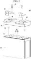
- FIG. 2 is an exploded perspective view of the rechargeable battery pack of FIG. 1
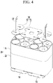
- FIG. 3 is a perspective view showing a state in which unit battery cells are assembled in a cell holder.
- a rechargeable battery pack 100 includes: a cell holder 20 for accommodating unit battery cells 10; a lower case 30 (first case) for accommodating the cell holder 20; an upper case 40 (second case) combined with the lower case 30; a tab 50 connecting the unit battery cells 10; and a terminal 60 connected to the tab 50.
- the unit battery cells 10 used for the first exemplary embodiment consist of cylindrical rechargeable batteries.
- rechargeable batteries may be used as the unit battery cells 10, a detailed description of them will be omitted.
- the unit battery cells may consist of prism-shaped or pouch-shaped rechargeable batteries in other embodiments.
- the cell holder 20 may be handled as a single cell assembly that accommodates a plurality of unit battery cells 10.
- the cell holder 20 comprises an upper holder 21 and a lower holder 22 that are combined with each other in its length direction, and is configured to accommodate eight cylindrical rechargeable batteries as an example.
- the cell holder 20 is provided with receiving holes corresponding to outward shapes (cylindrical or prismatic shape) of the unit battery cells 10.
- the lower case 30 accommodates the cell holder 20 as the cell assembly in which the unit battery cells 10 is accommodated, and is combined with the upper case 40, thereby forming an outward shape of the rechargeable battery pack 100.
- the upper case 40 is provided with a hook 41, which is combined with a catching groove 31 that is formed in an opening of the lower case 30.
- the upper case 40 can maintain its combined state with the opening of the lower case 30.
- a disassembly and assembly structure of the catching groove 31 and the hook 41 makes it easier to disassemble and assemble the rechargeable battery pack 100 when repair work is needed.
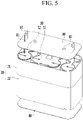
- FIG. 4 is a perspective view showing a state in which the unit battery cells are connected by the tab after the state of FIG. 3
- FIG. 5 is a perspective view showing a state in which insulating tapes are attached to the tab after the state of FIG. 4
- FIG. 6 is a perspective view showing a state in which the cell assembly is inserted into the lower case and then the upper case is assembled thereto.
- the tab 50 electrically connects the unit battery cells 10, and is drawn out (protruded out) of through-holes 42 that are provided in the upper case 40 such that it is bent outside of the upper case 40 to be disposed on an outer surface thereof.
- the tab 50 can protrude through the through-hole of the upper case 40, and then bend so as to make contact with an outer surface of the upper case 40.
- the terminal 60 can then overlap the tab 50 (including the bent portion) so as to cover the through hole 42.
- the tab 50 connects the unit battery cells 10 in series or in parallel by welding, and may have various shapes for this purpose in embodiments of the invention.
- the tab 50 is formed to connect eight battery unit cells in series by connecting two unit battery cells in parallel in this embodiment of the invention.
- the tab 50 is formed with a 4-cell reception tab 51 for connecting four unit battery cells 10 and a 2-cell reception tab 52 for connecting two unit battery cells 10.
- two 4-cell reception tabs 51 respectively connect four battery cells units at lateral sides.
- one 4-cell reception tab 51 connects four intermediate cell units 10, and two 2-cell reception tabs 52 respectively connect two unit battery cells 10 at lateral sides.
- the two 2-cell reception tabs 52 electrically connect the two unit battery cells 10, and are drawn out of the through-holes 42 of the upper case 40 such that they are disposed outside of the upper case 40 on the outer surface thereof as a bent end portion 53.
- insulating tapes 80 are disposed on upper and lower parts of the cell holder 20 such that they are respectively attached to top and bottom surfaces of the tab 50.
- the insulating tapes 80 prevent inflow of materials to prevent a short-circuit between the unit battery cells 10.
- the insulating tape 80 is provided with a first through-hole 81 through which the end portion 53 of the tab 50 penetrates and a second through-hole 82 through which a fastening member 70 to be described later penetrates.
- the cell holder 20 is inserted into the lower case 30 through an opening of the lower case 30 while accommodating the unit battery cells 10 so as to be accommodated in the lower case 30.
- the unit battery cells 10 are electrically connected to each other through the tab 50, and the tab 50 remains coated by the insulating tape 80.
- the upper case 40 is combined with the opening of the lower case 30.
- the tab 50 is drawn out of the upper case 40 through the through-hole 42 provided in the upper case 40.
- the drawn-out end portion 53 of the tab 50 is bent outside the upper case 40 to be disposed on the outer surface thereof.
- the terminal 60 is disposed on the bent end portion 53 of the tab 50 so as to be electrically connected thereto.
- FIG. 7 is an exploded perspective view of the tab and the terminal according to the first exemplary embodiment of the present invention
- FIG. 8 is a top plan view of FIG. 1
- FIG. 9 is a cross-sectional view of FIG. 8 taken along the line IX-IX.
- the terminal 60 is combined with the upper case 40 while covering the through-hole 42.
- the tab 50 may make surface contact with the terminal 60 outside of the upper case 40.
- the tab 50 can connect with the terminal 60 outside of the upper case 40.
- a plate-shaped supporting portion 43 is provided in the upper case 40 so as to support the bent end portion 53 of the tab 50.
- the terminal 60 includes a tab connection portion 61 that is overlappingly disposed on the end portion 53 of the tab 50 above the supporting portion 43 for surface contact.
- the terminal 60 further includes a load connection portion 62 that crosses the tab connection portion 61 at one side thereof to be continuously bent in a vertical direction (z-axis direction), a horizontal direction (y-axis direction), and a vertical direction (z-axis direction) for connection with an external load (not shown).
- the load connection portion 62 can bend in a direction parallel to the protrusion direction of the tab through the through hole, a direction perpendicular to the protrusion direction of the tab through the through hole, and a direction parallel to the protrusion direction of the tab through the through hole.
- the tab 50 and the terminal 60 are spaced apart from the through-hole 42 by a predetermined distance D at one side such that they are fastened to the upper case 40 by the fastening member 70.
- the fastening member 70 penetrates through the tab connection portion 61 of the terminal 60 and the end portion 53 of the tab 50 such that it is fastened to the supporting portion 43 of the upper case 40.
- the end portion 53 of the tab 50 and the tab connection portion 61 of the terminal 60 may make surface contact with each other above the supporting portion 43.
- the tab 50 and the terminal 60 may be able to form and maintain a structure for stable electrical connection.
- the fastening member 70 when being elongated enough to penetrate through the insulating tape 80, the fastening member 70 may penetrate through the second through-hole 82 to be electrically separated from the tab 50.
- the upper case 40 is provided with a first supporting protrusion 441 that protrudes to cover the through-hole 42 from above, and the terminal 60 is supported by the first supporting protrusion 441 as the tab connection portion 61 at a side of the through-hole 42.
- the tab connection portion 61 of the terminal 60 is supported by the first supporting protrusion 441 by covering the through-hole 42, and makes surface contact with the end portion 53 of the tab 50 for electrical connection, thereby being fixed to the fastening member 70.
- the rechargeable battery pack 100 with water resistance is implemented.
- the tab connection portion 61 of the terminal 60 is slidingly inserted on the supporting portion 43 such that its one end is supported by the first supporting protrusion 441.
- the other end of the tab connection portion 61 is connected to the end portion 53 of the tab 50 by the fastening member 70 so as to be fixed to the supporting portion 43.
- the tab connection portion 61 may be able to make stable surface contact with the end portion 53 above the supporting portion 43.
- the upper case 40 is formed with a first insertion groove 451 corresponding to the tab connection portion 61 below the first supporting protrusion 441.
- the first insertion groove 451 causes the tab connection portion 61 to be slidingly inserted in the first supporting protrusion 441 such that the tab connection portion 61 is more firmly supported by the first supporting protrusion 441, and may be able to further maintain the insertion state.
- a structure in which the tab connection portion 61 is slidingly combined with the first supporting protrusion 441 and the first insertion groove 451 and in which the tab connection portion 61 is combined with the end portion 53 of the tab 30 by the fastening member 70 makes disassembly and assembly of the rechargeable battery pack 100 easier when doing repairs.
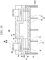
- FIG. 10 is a cross-sectional view of FIG. 8 taken along the line X-X
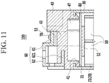
- FIG. 11 is a cross-sectional view of FIG. 8 taken along the line XI-XI.
- the upper case 40 is formed with a coupling groove 46 corresponding to the load connection portion 62.
- the load connection portion 62 further includes a coupling portion 621 that is bent in a horizontal direction of the tab connection portion 61 to be combined with the coupling groove 46.
- the load connection portion 62 is firmly combined with the upper case 40 in the terminal 60, and may be able to maintain a stable electrical connection when a load is connected.
- a slidingly coupled structure between the coupling portion 621 of the terminal 60 and the coupling groove 46 not only makes the disassembly and assembly of the rechargeable battery pack 100 easier when doing repairs, but also makes the surface contact between the tab connection portion 61 of the terminal 60 and the end portion 53 of the tab 50 more stable.
- the upper case 40 is further provided with a pressing portion 47 at its inner lower part.
- the pressing portion 47 protrudes toward inside of the lower case 30 to press the tab 50 and the unit battery cells 10 accommodated in the lower case 30 while being coupled therewith.
- the pressing portion 47 presses the insulating tape 80 provided on a top surface of the tab 50 to prevent the unit battery cells 10 from moving around inside the lower and upper cases 30 and 40 while maintaining an electrical connection between the tab 50 and the unit battery cells 10.
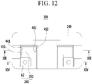
- FIG. 12 is a top plan view of the rechargeable battery pack according to a second exemplary embodiment of the present invention
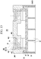
- FIG. 13 is a cross-sectional view of FIG. 12 taken along the line XII-XIII
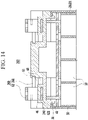
- FIG. 14 is a cross-sectional view of FIG. 12 taken along the line XIV-XIV.
- an upper case 240 is provided with a first supporting protrusion 441 that protrudes to cover the through-hole 42 at one side, and a second supporting protrusion 442 that protrudes at the other side to face the first supporting protrusion 441.
- a terminal 260 is supported by the first and second supporting protrusions 441 and 442 with a tab connection portion 261.
- the tab connection portion 261 may be able to maintain stable surface contact with the end portion 53 on the supporting portion 43.
- the upper case 240 is provided with a first insertion groove 451 corresponding to the tab connection portion 261 below the first supporting protrusion 441, and a second insertion groove 452 corresponding to the tab connection portion 261 below the second supporting protrusion 442.
- the first and second insertion grooves 451 and 452 cause the tab connection portion 261 to be slidingly inserted in the first and second supporting protrusions 441 and 442 such that the tab connection portion 261 is more firmly supported by the first and second supporting protrusions 441 and 442, and may be able to further maintain the insertion state.
- the coupling portion 621 of the load connection portion 62 is slidingly combined with a coupling groove 46 of the upper case 240.
- the load connection portion 62 is firmly combined with the upper case 240 in the terminal 260, and may be able to maintain a stable electrical connection when a load is connected.
- FIG. 15 is a cross-sectional view of a rechargeable battery pack according to a third exemplary embodiment of the present invention.
- a first insertion groove 453 and a lateral part of a tab connection portion 361 combined with the first insertion groove 453 respectively have circular shapes in cross-sections perpendicular to an insertion direction of the tab connection portion 361.
- the first insertion groove 453 causes the tab connection portion 361 to be slidingly inserted in the first supporting protrusion 443 such that the tab connection portion 361 is more firmly supported by the first supporting protrusion 443, and may be able to further maintain the insertion state.
- the load connection portion 62 is firmly combined with the upper case 340 in the terminal 360, and may be able to maintain a stable electrical connection when a load is connected.
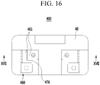
- FIG. 16 is a top plan view of a rechargeable battery pack according to a fourth exemplary embodiment of the present invention
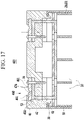
- FIG. 17 is a cross-sectional view of FIG. 16 taken along the line XVII-XVII.
- a terminal 460 of a tab connection portion 461 is provided with a dew discharging groove 476 at an outer part of the through-hole 42.
- the dew discharging groove 476 is formed outside the upper case 40 and at an outer side of the terminal 460 to direct dew and other moisture collected in the terminal 460 in a direction away from the through-hole 42, thereby preventing a short-circuit between the unit battery cells 10 due to the dew.
- embodiments of the invention can provide a rechargeable battery pack comprising: a cell holder for accommodating unit battery cells; a first case for accommodating the cell holder; a second case combined with an opening of the first case to cover the cell holder and the unit battery cells; a tab connected to the unit battery cells, the tab having an end portion protruding out of a through-hole of the second case so as to be disposed on an outer surface of the second case; and a terminal electrically connected to the end portion of the tab and overlapping therewith, the terminal being combined with the second case to cover the through-hole.
- the tab can protrude through the through-hole of the second case, and then bend so as to enable the end portion to make contact with an outer surface of the second case.
- the terminal can then overlap the tab (including the bent portion and at least part of the end portion) so as to cover the through hole.
- the second case is provided with a plate-shaped supporting portion arranged to support the end portion that is bent from the tab.
- the plate-shaped supporting portion can form at least part of the outer surface of the second case that the tab bends to contact.
- the terminal can include a tab connection portion that is disposed on the end portion to make surface contact therewith.
- the second case can be provided with a first supporting protrusion that is arranged to protrude to cover the through-hole, with the tab connection portion of the terminal is supported by the first supporting protrusion.
- the tab connection portion can be between the first supporting protrusion and the bent portion of the tab.
- the second case can be provided with a first supporting protrusion that protrudes to cover the through-hole and a second supporting protrusion that protrudes at an opposite side of the first supporting protrusion, with the tab connection portion is supported by the first and second supporting protrusions.
- the tab connection portion can be between the first supporting protrusion and the bent portion of the tab.
Landscapes
- Chemical & Material Sciences (AREA)
- Chemical Kinetics & Catalysis (AREA)
- Electrochemistry (AREA)
- General Chemical & Material Sciences (AREA)
- Engineering & Computer Science (AREA)
- Aviation & Aerospace Engineering (AREA)
- Connection Of Batteries Or Terminals (AREA)
- Battery Mounting, Suspending (AREA)
Description
- The described technology relates generally to a rechargeable battery pack used for starting an engine of a 2-wheel or 4-wheel vehicle.
- A 2-wheel vehicle and a 4-wheel vehicle are generally provided with a battery pack for starting their engines.
- A lead storage battery is generally used as the battery pack for starting an engine.
- The lead storage battery pack is typically sealed by ultrasonic welding to prevent moisture permeation.
- However, a structure formed by the ultrasonic welding makes it difficult to disassemble the pack when repair work on the pack is required.
-
EP2500964 A2 discloses a secondary battery and a secondary battery pack. The secondary battery includes a case, an electrode assembly, a cap plate, a flexible connecting tab and a terminal plate. The secondary battery pack includes bus bars to connect the secondary batteries. - The above information disclosed in this Background section is only for enhancement of understanding of the background of the described technology and therefore it may contain information that does not form the prior art that is already known in this country to a person of ordinary skill in the art.
- The described technology has been made in an effort to provide a rechargeable battery pack that is capable of allowing easy disassembly for repair work and waterproof performance during operation.
- According to an aspect of the invention, there is provided a rechargeable battery pack as set out in claim 1. Preferred features are set out in claims 2 to 12.
- Accordingly, the present exemplary embodiment makes the disassembly and assembly work easier during repair work, and the terminal covers the through-hole of the upper case, thereby implementing water resistance when the rechargeable battery pack is used.
- The tab and the terminal may make surface contact with each other outside of the upper case.
-
FIG. 1 is a perspective view of a rechargeable battery pack according to a first exemplary embodiment of the present invention. -
FIG. 2 is an exploded perspective view of the rechargeable battery pack ofFIG. 1 . -
FIG. 3 is a perspective view showing a state in which unit battery cells are assembled in a cell holder. -
FIG. 4 is a perspective view showing a state in which the unit battery cells are connected by a tab after the state ofFIG. 3 . -
FIG. 5 is a perspective view showing a state in which insulating tapes are attached to the tab after the state ofFIG. 4 . -
FIG. 6 is a perspective view showing a state in which a cell assembly is inserted into a lower case and then an upper case is assembled. - The upper case may be provided with a first insertion groove that corresponds to the tab connection portion below the first supporting protrusion, and a second insertion groove that corresponds to the tab connection portion below the second supporting protrusion.
- The terminal may include a tab connection portion that is disposed on the end portion to make surface contact therewith, and the tab connection portion may be provided with a dew discharging groove at an outer part of the through-hole. As described above, in the exemplary embodiment, the tab to which the unit battery cells are connected is drawn out of the through-hole to be bent on the outer surface of the upper case, and the terminal is disposed on the tab to be electrically connected thereto and to be combined with the upper case while covering the through-hole.
- That is, in the rechargeable battery pack, the terminal may be separable from the tab and the upper case may be separable from the lower case.
- According to an aspect of the invention, there is provided a rechargeable battery pack as set out in claim 1. Preferred features are set out in claims 2 to 13.
- Accordingly, the present exemplary embodiment makes the disassembly and assembly work easier during repair work, and the terminal covers the through-hole of the upper case, thereby implementing water resistance when the rechargeable battery pack is used.
-
FIG. 1 is a perspective view of a rechargeable battery pack according to a first exemplary embodiment of the present invention. -
FIG. 2 is an exploded perspective view of the rechargeable battery pack ofFIG. 1 . -
FIG. 3 is a perspective view showing a state in which unit battery cells are assembled in a cell holder. -
FIG. 4 is a perspective view showing a state in which the unit battery cells are connected by a tab after the state ofFIG. 3 . -
FIG. 5 is a perspective view showing a state in which insulating tapes are attached to the tab after the state ofFIG. 4 . -
FIG. 6 is a perspective view showing a state in which a cell assembly is inserted into a lower case and then an upper case is assembled. -
FIG. 7 is an exploded perspective view of the tab and a terminal according to the first exemplary embodiment of the present invention. -
FIG. 8 is a top plan view ofFIG. 1 . -
FIG. 9 is a cross-sectional view ofFIG. 8 taken along the line IX-IX. -
FIG. 10 is a cross-sectional view ofFIG. 8 taken along the line X-X. -
FIG. 11 is a cross-sectional view ofFIG. 8 taken along the line XI-XI. -
FIG. 12 is a top plan view of a rechargeable battery pack according to a second exemplary embodiment of the present invention. -
FIG. 13 is a cross-sectional view ofFIG. 12 taken along the line XIII-XIII. -
FIG. 14 is a cross-sectional view ofFIG. 12 taken along the line XIV-XIV. -
FIG. 15 is a cross-sectional view of a rechargeable battery pack according to a third exemplary embodiment of the present invention. -
FIG. 16 is a top plan view of a rechargeable battery pack according to a fourth exemplary embodiment of the present invention. -
FIG. 17 is a cross-sectional view ofFIG. 16 taken along the line XVII-XVII. - The present invention will be described more fully hereinafter with reference to the accompanying drawings, in which exemplary embodiments of the invention are shown.
- As those skilled in the art would realize, the described embodiments may be modified in various different ways, all without departing from the scope of the present invention.
- The drawings and description are to be regarded as illustrative in nature and not restrictive. Like reference numerals designate like elements throughout the specification.
-
FIG. 1 is a perspective view of a rechargeable battery pack according to a first exemplary embodiment of the present invention,FIG. 2 is an exploded perspective view of the rechargeable battery pack ofFIG. 1 , andFIG. 3 is a perspective view showing a state in which unit battery cells are assembled in a cell holder. - Referring to
FIGS. 1 to 3 , arechargeable battery pack 100 according to a first exemplary embodiment includes: acell holder 20 for accommodatingunit battery cells 10; a lower case 30 (first case) for accommodating thecell holder 20; an upper case 40 (second case) combined with thelower case 30; atab 50 connecting theunit battery cells 10; and aterminal 60 connected to thetab 50. - The
unit battery cells 10 used for the first exemplary embodiment consist of cylindrical rechargeable batteries. - Since disclosed rechargeable batteries may be used as the
unit battery cells 10, a detailed description of them will be omitted. - Though not illustrated, the unit battery cells may consist of prism-shaped or pouch-shaped rechargeable batteries in other embodiments.
- The
cell holder 20 may be handled as a single cell assembly that accommodates a plurality ofunit battery cells 10. - For example, the
cell holder 20 comprises anupper holder 21 and alower holder 22 that are combined with each other in its length direction, and is configured to accommodate eight cylindrical rechargeable batteries as an example. - The
cell holder 20 is provided with receiving holes corresponding to outward shapes (cylindrical or prismatic shape) of theunit battery cells 10. - The
lower case 30 accommodates thecell holder 20 as the cell assembly in which theunit battery cells 10 is accommodated, and is combined with theupper case 40, thereby forming an outward shape of therechargeable battery pack 100. - As an example, the
upper case 40 is provided with ahook 41, which is combined with acatching groove 31 that is formed in an opening of thelower case 30. - By combining the
hook 41 with thecatching groove 31, theupper case 40 can maintain its combined state with the opening of thelower case 30. - A disassembly and assembly structure of the
catching groove 31 and thehook 41 makes it easier to disassemble and assemble therechargeable battery pack 100 when repair work is needed. -
FIG. 4 is a perspective view showing a state in which the unit battery cells are connected by the tab after the state ofFIG. 3 ,FIG. 5 is a perspective view showing a state in which insulating tapes are attached to the tab after the state ofFIG. 4 , andFIG. 6 is a perspective view showing a state in which the cell assembly is inserted into the lower case and then the upper case is assembled thereto. - Referring to
FIGS. 4 to 6 , thetab 50 electrically connects theunit battery cells 10, and is drawn out (protruded out) of through-holes 42 that are provided in theupper case 40 such that it is bent outside of theupper case 40 to be disposed on an outer surface thereof. Thetab 50 can protrude through the through-hole of theupper case 40, and then bend so as to make contact with an outer surface of theupper case 40. Theterminal 60 can then overlap the tab 50 (including the bent portion) so as to cover the throughhole 42. - The
tab 50 connects theunit battery cells 10 in series or in parallel by welding, and may have various shapes for this purpose in embodiments of the invention. - In
FIG. 4 , among theunit battery cells 10, thetab 50 is formed to connect eight battery unit cells in series by connecting two unit battery cells in parallel in this embodiment of the invention. - In the first exemplary embodiment, the
tab 50 is formed with a 4-cell reception tab 51 for connecting fourunit battery cells 10 and a 2-cell reception tab 52 for connecting twounit battery cells 10. - That is, at a lower part of
FIG. 4 , two 4-cell reception tabs 51 respectively connect four battery cells units at lateral sides. - At an upper part of
FIG. 4 , one 4-cell reception tab 51 connects fourintermediate cell units 10, and two 2-cell reception tabs 52 respectively connect twounit battery cells 10 at lateral sides. - The two 2-
cell reception tabs 52 electrically connect the twounit battery cells 10, and are drawn out of the through-holes 42 of theupper case 40 such that they are disposed outside of theupper case 40 on the outer surface thereof as abent end portion 53. - Referring to
FIG. 5 , insulatingtapes 80 are disposed on upper and lower parts of thecell holder 20 such that they are respectively attached to top and bottom surfaces of thetab 50. - The insulating
tapes 80 prevent inflow of materials to prevent a short-circuit between theunit battery cells 10. - The insulating
tape 80 is provided with a first through-hole 81 through which theend portion 53 of thetab 50 penetrates and a second through-hole 82 through which afastening member 70 to be described later penetrates. - Referring to
FIG. 6 , thecell holder 20 is inserted into thelower case 30 through an opening of thelower case 30 while accommodating theunit battery cells 10 so as to be accommodated in thelower case 30. - In this arrangement, the
unit battery cells 10 are electrically connected to each other through thetab 50, and thetab 50 remains coated by the insulatingtape 80. - Referring to
FIGS. 6 and2 , while theunit battery cells 10 are accommodated in thelower case 30, theupper case 40 is combined with the opening of thelower case 30. - In this case, the
tab 50 is drawn out of theupper case 40 through the through-hole 42 provided in theupper case 40. - Referring to
FIGS. 1 and2 , the drawn-outend portion 53 of thetab 50 is bent outside theupper case 40 to be disposed on the outer surface thereof. - The terminal 60 is disposed on the
bent end portion 53 of thetab 50 so as to be electrically connected thereto. -
FIG. 7 is an exploded perspective view of the tab and the terminal according to the first exemplary embodiment of the present invention,FIG. 8 is a top plan view ofFIG. 1 , andFIG. 9 is a cross-sectional view ofFIG. 8 taken along the line IX-IX. - Referring to
FIGS. 7 to 9 , the terminal 60 is combined with theupper case 40 while covering the through-hole 42. - In this case, the
tab 50 may make surface contact with the terminal 60 outside of theupper case 40. In other words, thetab 50 can connect with the terminal 60 outside of theupper case 40. - To this end, a plate-shaped supporting
portion 43 is provided in theupper case 40 so as to support thebent end portion 53 of thetab 50. - The terminal 60 includes a
tab connection portion 61 that is overlappingly disposed on theend portion 53 of thetab 50 above the supportingportion 43 for surface contact. - Further, the terminal 60 further includes a
load connection portion 62 that crosses thetab connection portion 61 at one side thereof to be continuously bent in a vertical direction (z-axis direction), a horizontal direction (y-axis direction), and a vertical direction (z-axis direction) for connection with an external load (not shown). Theload connection portion 62 can bend in a direction parallel to the protrusion direction of the tab through the through hole, a direction perpendicular to the protrusion direction of the tab through the through hole, and a direction parallel to the protrusion direction of the tab through the through hole. - The
tab 50 and the terminal 60 are spaced apart from the through-hole 42 by a predetermined distance D at one side such that they are fastened to theupper case 40 by thefastening member 70. - In this case, the
fastening member 70 penetrates through thetab connection portion 61 of the terminal 60 and theend portion 53 of thetab 50 such that it is fastened to the supportingportion 43 of theupper case 40. - By a fastening force of the
fastening member 70, theend portion 53 of thetab 50 and thetab connection portion 61 of the terminal 60 may make surface contact with each other above the supportingportion 43. - That is, the
tab 50 and the terminal 60 may be able to form and maintain a structure for stable electrical connection. - Though not illustrated, referring to
FIG. 9 , when being elongated enough to penetrate through the insulatingtape 80, thefastening member 70 may penetrate through the second through-hole 82 to be electrically separated from thetab 50. - Further, the
upper case 40 is provided with a first supportingprotrusion 441 that protrudes to cover the through-hole 42 from above, and the terminal 60 is supported by the first supportingprotrusion 441 as thetab connection portion 61 at a side of the through-hole 42. - The
tab connection portion 61 of the terminal 60 is supported by the first supportingprotrusion 441 by covering the through-hole 42, and makes surface contact with theend portion 53 of thetab 50 for electrical connection, thereby being fixed to thefastening member 70. - That is, in the
upper case 40 exposed outside, a part to which the terminal 60 is fixed and the through-hole 42 through which thetab 50 is drawn out are separated from each other, and the through-hole 42 is covered by the first supportingprotrusion 441. - Accordingly, if the
rechargeable battery pack 100 is used, moisture permeation through the through-hole 42, through which thetab 50 is drawn out, can be prevented. - That is, the
rechargeable battery pack 100 with water resistance is implemented. - The
tab connection portion 61 of the terminal 60 is slidingly inserted on the supportingportion 43 such that its one end is supported by the first supportingprotrusion 441. - Then, the other end of the
tab connection portion 61 is connected to theend portion 53 of thetab 50 by thefastening member 70 so as to be fixed to the supportingportion 43. - Thus, the
tab connection portion 61 may be able to make stable surface contact with theend portion 53 above the supportingportion 43. - Further, the
upper case 40 is formed with afirst insertion groove 451 corresponding to thetab connection portion 61 below the first supportingprotrusion 441. - The
first insertion groove 451 causes thetab connection portion 61 to be slidingly inserted in the first supportingprotrusion 441 such that thetab connection portion 61 is more firmly supported by the first supportingprotrusion 441, and may be able to further maintain the insertion state. - As such, a structure in which the
tab connection portion 61 is slidingly combined with the first supportingprotrusion 441 and thefirst insertion groove 451 and in which thetab connection portion 61 is combined with theend portion 53 of thetab 30 by thefastening member 70 makes disassembly and assembly of therechargeable battery pack 100 easier when doing repairs. -
FIG. 10 is a cross-sectional view ofFIG. 8 taken along the line X-X, andFIG. 11 is a cross-sectional view ofFIG. 8 taken along the line XI-XI. - Referring to
FIGS. 7 ,8 ,10 , and11 , theupper case 40 is formed with acoupling groove 46 corresponding to theload connection portion 62. - For its corresponding portion, the
load connection portion 62 further includes acoupling portion 621 that is bent in a horizontal direction of thetab connection portion 61 to be combined with thecoupling groove 46. - When the
tab connection portion 61 is slidingly combined with the first supportingprotrusion 441 and thefirst insertion groove 451, thecoupling portion 621 of theload connection portion 62 is slidingly combined with thecoupling groove 46 of theupper case 40. - Accordingly, the
load connection portion 62 is firmly combined with theupper case 40 in the terminal 60, and may be able to maintain a stable electrical connection when a load is connected. - A slidingly coupled structure between the
coupling portion 621 of the terminal 60 and thecoupling groove 46 not only makes the disassembly and assembly of therechargeable battery pack 100 easier when doing repairs, but also makes the surface contact between thetab connection portion 61 of the terminal 60 and theend portion 53 of thetab 50 more stable. - The
upper case 40 is further provided with apressing portion 47 at its inner lower part. - The
pressing portion 47 protrudes toward inside of thelower case 30 to press thetab 50 and theunit battery cells 10 accommodated in thelower case 30 while being coupled therewith. - In more detail, the
pressing portion 47 presses the insulatingtape 80 provided on a top surface of thetab 50 to prevent theunit battery cells 10 from moving around inside the lower andupper cases tab 50 and theunit battery cells 10. - Various exemplary embodiments will now be described.
- A description of the same constituent elements as the first exemplary embodiment and the aforementioned exemplary embodiments will be omitted.
-
FIG. 12 is a top plan view of the rechargeable battery pack according to a second exemplary embodiment of the present invention,FIG. 13 is a cross-sectional view ofFIG. 12 taken along the line XII-XIII, andFIG. 14 is a cross-sectional view ofFIG. 12 taken along the line XIV-XIV. - Referring to
FIGS. 12 to 14 , in arechargeable battery pack 200 according to the second exemplary embodiment of the present invention, anupper case 240 is provided with a first supportingprotrusion 441 that protrudes to cover the through-hole 42 at one side, and a second supportingprotrusion 442 that protrudes at the other side to face the first supportingprotrusion 441. - A terminal 260 is supported by the first and second supporting
protrusions tab connection portion 261. - Thus, the
tab connection portion 261 may be able to maintain stable surface contact with theend portion 53 on the supportingportion 43. - The
upper case 240 is provided with afirst insertion groove 451 corresponding to thetab connection portion 261 below the first supportingprotrusion 441, and asecond insertion groove 452 corresponding to thetab connection portion 261 below the second supportingprotrusion 442. - The first and
second insertion grooves tab connection portion 261 to be slidingly inserted in the first and second supportingprotrusions tab connection portion 261 is more firmly supported by the first and second supportingprotrusions - As such, when the
tab connection portion 261 is slidingly combined with both the first and second supportingprotrusions second insertion grooves coupling portion 621 of theload connection portion 62 is slidingly combined with acoupling groove 46 of theupper case 240. - Accordingly, the
load connection portion 62 is firmly combined with theupper case 240 in the terminal 260, and may be able to maintain a stable electrical connection when a load is connected. -
FIG. 15 is a cross-sectional view of a rechargeable battery pack according to a third exemplary embodiment of the present invention. - Referring to
FIG. 15 , in arechargeable battery pack 300 according to the third exemplary embodiment of the present invention, afirst insertion groove 453 and a lateral part of atab connection portion 361 combined with thefirst insertion groove 453 respectively have circular shapes in cross-sections perpendicular to an insertion direction of thetab connection portion 361. - The
first insertion groove 453 causes thetab connection portion 361 to be slidingly inserted in the first supportingprotrusion 443 such that thetab connection portion 361 is more firmly supported by the first supportingprotrusion 443, and may be able to further maintain the insertion state. - When the
tab connection portion 361 of a terminal 360 is slidingly combined with both the first supportingprotrusion 443 and thefirst insertion groove 453, thecoupling portion 621 of theload connection portion 62 is slidingly combined with acoupling groove 46 of anupper case 340. - Accordingly, the
load connection portion 62 is firmly combined with theupper case 340 in the terminal 360, and may be able to maintain a stable electrical connection when a load is connected. -
FIG. 16 is a top plan view of a rechargeable battery pack according to a fourth exemplary embodiment of the present invention, andFIG. 17 is a cross-sectional view ofFIG. 16 taken along the line XVII-XVII. - Referring to
FIGS. 16 and17 , in therechargeable battery pack 400 according to a fourth exemplary embodiment, aterminal 460 of atab connection portion 461 is provided with adew discharging groove 476 at an outer part of the through-hole 42. - The
dew discharging groove 476 is formed outside theupper case 40 and at an outer side of the terminal 460 to direct dew and other moisture collected in the terminal 460 in a direction away from the through-hole 42, thereby preventing a short-circuit between theunit battery cells 10 due to the dew. - As discussed, embodiments of the invention can provide a rechargeable battery pack comprising: a cell holder for accommodating unit battery cells; a first case for accommodating the cell holder; a second case combined with an opening of the first case to cover the cell holder and the unit battery cells; a tab connected to the unit battery cells, the tab having an end portion protruding out of a through-hole of the second case so as to be disposed on an outer surface of the second case; and a terminal electrically connected to the end portion of the tab and overlapping therewith, the terminal being combined with the second case to cover the through-hole.
- The tab can protrude through the through-hole of the second case, and then bend so as to enable the end portion to make contact with an outer surface of the second case. The terminal can then overlap the tab (including the bent portion and at least part of the end portion) so as to cover the through hole.
- In some embodiments, the second case is provided with a plate-shaped supporting portion arranged to support the end portion that is bent from the tab. Hence, the plate-shaped supporting portion can form at least part of the outer surface of the second case that the tab bends to contact. The terminal can include a tab connection portion that is disposed on the end portion to make surface contact therewith.
- The second case can be provided with a first supporting protrusion that is arranged to protrude to cover the through-hole, with the tab connection portion of the terminal is supported by the first supporting protrusion. In such embodiments, the tab connection portion can be between the first supporting protrusion and the bent portion of the tab.
- The second case can be provided with a first supporting protrusion that protrudes to cover the through-hole and a second supporting protrusion that protrudes at an opposite side of the first supporting protrusion, with the tab connection portion is supported by the first and second supporting protrusions. In such embodiments, the tab connection portion can be between the first supporting protrusion and the bent portion of the tab.
- While this invention has been described in connection with what is presently considered to be practical exemplary embodiments, it is to be understood that the invention is not limited to the disclosed embodiments, but, on the contrary, is intended to cover various modifications and equivalent arrangements included within the scope of the appended claims.
Claims (12)
- A rechargeable battery pack comprising:a plurality of unit battery cells (10);a cell holder (20) arranged to accommodate the unit battery cells (10);a first case (30) arranged to accommodate the cell holder, the first case having an opening;a second case (40, 240, 340) arranged to be combined with the first case to cover the opening of the first case so that the first case and the second case cover the cell holder and the unit battery cells, wherein the first case is separable from the second case;a tab (50) connected to the unit battery cells, the tab having an end portion (53) protruding out of a through-hole of the second case so as to be bent outside of the second case and disposed on an outer surface of the second case; anda terminal (60, 260, 360, 460) disposed on the bent end portion of the tab and electrically connected to the bent end portion of the tab and overlapping therewith, the terminal being combined with the second case to cover the through-hole;wherein the tab and the terminal surface contact each other outside of the second case.
- The battery pack of claim 1, wherein the tab and the terminal are spaced apart by a predetermined distance from the through-hole and are fastened to the second case by a fastening member such that they make surface contact with each other.
- The battery pack of claim 1 or 2, wherein the second case is provided with a plate-shaped supporting portion (43) arranged to support the end portion that is bent from the tab, and the terminal includes a tab connection portion that is disposed on the end portion to make surface contact therewith.
- The battery pack of claim 3, wherein the second case is provided with a first supporting protrusion (441, 443) that is arranged to protrude to cover the through-hole, and the tab connection portion of the terminal is supported by the first supporting protrusion.
- The battery pack of claim 4, wherein the second case is formed with a first insertion groove (451, 453) corresponding to the tab connection portion that is between the first supporting protrusion and the tab.
- The battery pack of claim 5, wherein the first insertion groove and a lateral end of the tab connection portion combined with the first insertion groove respectively have circular shapes in cross-sections perpendicular to an insertion direction of the tab connection portion.
- The battery pack of claim 5 or 6, wherein the terminal includes a load connection portion (62) that is connected to the tab connection portion, and wherein the second case is formed with a coupling groove corresponding to the load connection portion, and the load connection portion further includes a coupling portion that is bent from the tab connection portion to be connected to the coupling groove.
- The battery pack of any one of claims 4 to 7, wherein the terminal includes a load connection portion (62) connected to the tab connection portion at one side thereof to be bent in a direction parallel to the protrusion direction of the tab through the through hole, a direction perpendicular to the protrusion direction of the tab through the through hole, and a direction parallel to the protrusion direction of the tab through the through hole.
- The battery pack of any one of claims 1 to 8, further comprising a pressing portion included in the second case, the pressing portion protruding toward the inside of the first case arranged to press the tab and the unit battery cells together.
- The battery pack of any one of claims 1 to 3, wherein the second case is provided with a first supporting protrusion that protrudes to cover the through-hole and a second supporting protrusion that protrudes at an opposite side of the first supporting protrusion, and the tab connection portion is supported by the first and second supporting protrusions.
- The battery pack of claim 10, wherein the second case is provided with a first insertion groove that corresponds to the tab connection portion between the first supporting protrusion and the tab, and a second insertion groove that corresponds to the tab connection portion between the second supporting protrusion and the tab.
- The battery pack of any one of claims 1 to 11, wherein the terminal includes a tab connection portion that is disposed on the end portion to make surface contact therewith, and the tab connection portion is provided with a dew discharging groove at an outer part of the through-hole.
Applications Claiming Priority (1)
| Application Number | Priority Date | Filing Date | Title |
|---|---|---|---|
| KR1020140006878A KR102101751B1 (en) | 2014-01-20 | 2014-01-20 | Rechargeable battery pack |
Publications (2)
| Publication Number | Publication Date |
|---|---|
| EP2897193A1 EP2897193A1 (en) | 2015-07-22 |
| EP2897193B1 true EP2897193B1 (en) | 2022-08-10 |
Family
ID=51987079
Family Applications (1)
| Application Number | Title | Priority Date | Filing Date |
|---|---|---|---|
| EP14195498.2A Active EP2897193B1 (en) | 2014-01-20 | 2014-11-28 | Rechargeable battery pack |
Country Status (7)
| Country | Link |
|---|---|
| US (1) | US10050243B2 (en) |
| EP (1) | EP2897193B1 (en) |
| JP (1) | JP6490953B2 (en) |
| KR (1) | KR102101751B1 (en) |
| HU (1) | HUE060083T2 (en) |
| IN (1) | IN2015DE00166A (en) |
| PL (1) | PL2897193T3 (en) |
Families Citing this family (13)
| Publication number | Priority date | Publication date | Assignee | Title |
|---|---|---|---|---|
| USD753587S1 (en) * | 2013-12-24 | 2016-04-12 | Gs Yuasa International Ltd. | Lead-acid battery |
| USD753586S1 (en) * | 2013-12-24 | 2016-04-12 | Gs Yuasa International Ltd. | Lead-acid battery |
| US10529962B2 (en) * | 2015-09-29 | 2020-01-07 | Panasonic Intellectual Property Management Co., Ltd. | Storage cell and power storage device in which same is used |
| KR102495848B1 (en) * | 2016-01-12 | 2023-02-06 | (주)유브릿지 | Battery Case using Battery Package |
| CN105977436B (en) * | 2016-06-29 | 2018-08-03 | 深圳市国创动力系统有限公司 | Battery pack exports end connection |
| JP7094697B2 (en) * | 2017-12-25 | 2022-07-04 | 矢崎総業株式会社 | Battery pack |
| KR102508167B1 (en) * | 2018-02-23 | 2023-03-09 | 삼성에스디아이 주식회사 | Battery pack |
| CN109273629A (en) * | 2018-09-30 | 2019-01-25 | 广州市凯捷电源实业有限公司 | A kind of replaceable terminal battery cover structure |
| CN111354987B (en) | 2018-12-23 | 2021-05-11 | 宁德时代新能源科技股份有限公司 | Battery module |
| CN109802060A (en) * | 2018-12-26 | 2019-05-24 | 安徽理士电源技术有限公司 | A kind of electrode column sealing part of integral type fixed tubular type pregnant solution type battery |
| JPWO2021111844A1 (en) * | 2019-12-03 | 2021-06-10 | ||
| EP3979401A1 (en) * | 2020-09-30 | 2022-04-06 | Andreas Stihl AG & Co. KG | Battery pack assembly for supplying an electrically powered processing device with electrical drive, battery pack, processing system and method of manufacturing a battery pack |
| KR20240094615A (en) * | 2022-12-16 | 2024-06-25 | 주식회사 엘지에너지솔루션 | Battery cell with insulation film having a function for preventing short circuit by dew, and battery module comprising the same |
Family Cites Families (15)
| Publication number | Priority date | Publication date | Assignee | Title |
|---|---|---|---|---|
| JP2003142072A (en) * | 2001-10-31 | 2003-05-16 | Furukawa Battery Co Ltd:The | Terminal structure of storage battery |
| JP2005197192A (en) * | 2004-01-09 | 2005-07-21 | Sanyo Electric Co Ltd | Pack cell and its assembling method |
| JP5521279B2 (en) * | 2008-04-25 | 2014-06-11 | 株式会社Gsユアサ | Storage battery |
| EP2273586B1 (en) * | 2008-04-25 | 2019-07-31 | GS Yuasa International Ltd. | Storage battery |
| KR101015834B1 (en) | 2009-01-06 | 2011-02-23 | 에스비리모티브 주식회사 | Battery module |
| WO2010141854A1 (en) * | 2009-06-05 | 2010-12-09 | K2 Energy Solutions, Inc. | Lithium ion battery pack having passive cooling |
| US9246140B2 (en) | 2009-07-09 | 2016-01-26 | Samsung Sdi Co., Ltd. | Rechargeable battery with a cap assembly having a first tab located outside of the case |
| JP5452252B2 (en) * | 2010-01-27 | 2014-03-26 | 三洋電機株式会社 | Battery system |
| JP2011222409A (en) | 2010-04-13 | 2011-11-04 | Might Industry Co Ltd | Lithium ion battery pack, power supply device using the same, and battery floodlight |
| JP2012089323A (en) * | 2010-10-19 | 2012-05-10 | Nifco Inc | Electrode formation for battery module |
| WO2012060178A1 (en) * | 2010-11-04 | 2012-05-10 | 株式会社マキタ | Battery pack |
| CN103201876B (en) * | 2010-11-17 | 2015-11-25 | 本田技研工业株式会社 | Vehicle battery unit |
| US9537121B2 (en) * | 2011-03-18 | 2017-01-03 | Samsung Sdi Co., Ltd. | Secondary battery and secondary battery pack having a flexible collecting tab extending through a cap plate |
| KR101731318B1 (en) | 2011-10-20 | 2017-04-28 | 에스케이이노베이션 주식회사 | Battery module improved electric insulation |
| KR101478704B1 (en) * | 2012-03-30 | 2015-01-02 | 주식회사 엘지화학 | Battery Module of Novel Structure and Battery Pack Comprising the Same |
-
2014
- 2014-01-20 KR KR1020140006878A patent/KR102101751B1/en active IP Right Grant
- 2014-11-21 US US14/550,891 patent/US10050243B2/en active Active
- 2014-11-27 JP JP2014239779A patent/JP6490953B2/en active Active
- 2014-11-28 HU HUE14195498A patent/HUE060083T2/en unknown
- 2014-11-28 PL PL14195498.2T patent/PL2897193T3/en unknown
- 2014-11-28 EP EP14195498.2A patent/EP2897193B1/en active Active
-
2015
- 2015-01-19 IN IN166DE2015 patent/IN2015DE00166A/en unknown
Also Published As
| Publication number | Publication date |
|---|---|
| JP6490953B2 (en) | 2019-03-27 |
| IN2015DE00166A (en) | 2015-07-24 |
| PL2897193T3 (en) | 2022-11-07 |
| KR20150086802A (en) | 2015-07-29 |
| HUE060083T2 (en) | 2023-01-28 |
| KR102101751B1 (en) | 2020-04-20 |
| EP2897193A1 (en) | 2015-07-22 |
| US20150207117A1 (en) | 2015-07-23 |
| US10050243B2 (en) | 2018-08-14 |
| JP2015138781A (en) | 2015-07-30 |
Similar Documents
| Publication | Publication Date | Title |
|---|---|---|
| EP2897193B1 (en) | Rechargeable battery pack | |
| KR102056875B1 (en) | Battery module and battery pack including the same | |
| KR102259416B1 (en) | Battery Module Having Bus bar Assembly | |
| KR101808310B1 (en) | Compact secondary battery module integrated with BMS | |
| CN101346832B (en) | Frame member and battery pack employed with the same | |
| JP5269018B2 (en) | Battery pack and bus bar holder | |
| CN101820053B (en) | Battery pack spacer | |
| EP2562842B1 (en) | Battery module | |
| KR102444124B1 (en) | Battery module and battery pack having the same | |
| US10992008B2 (en) | Drawer-type battery pack | |
| US20170110698A1 (en) | Rechargeable battery module | |
| JP2011243561A (en) | Battery pack | |
| US11108115B2 (en) | Battery case and battery module | |
| US11469472B2 (en) | Battery pack having waterproof function and manufacturing method therefor | |
| EP3836270A1 (en) | Battery pack | |
| CA2593944A1 (en) | Fuel cell stack | |
| US20160028131A1 (en) | Battery module | |
| EP3154108B1 (en) | Battery module and battery pack including same | |
| KR20170050511A (en) | Battery module and battery pack including the same | |
| KR102115481B1 (en) | Compact secondary battery module integrated with BMS | |
| US20160226034A1 (en) | Energy storage device | |
| EP3540814B1 (en) | End plate, housing, and battery module | |
| KR102056366B1 (en) | Cell module for secondary battery pack and assembly method for the same | |
| EP3252846B1 (en) | Battery cell assembly | |
| KR20140002112A (en) | Battery module |
Legal Events
| Date | Code | Title | Description |
|---|---|---|---|
| PUAI | Public reference made under article 153(3) epc to a published international application that has entered the european phase |
Free format text: ORIGINAL CODE: 0009012 |
|
| 17P | Request for examination filed |
Effective date: 20141128 |
|
| AK | Designated contracting states |
Kind code of ref document: A1 Designated state(s): AL AT BE BG CH CY CZ DE DK EE ES FI FR GB GR HR HU IE IS IT LI LT LU LV MC MK MT NL NO PL PT RO RS SE SI SK SM TR |
|
| AX | Request for extension of the european patent |
Extension state: BA ME |
|
| 17P | Request for examination filed |
Effective date: 20160122 |
|
| RBV | Designated contracting states (corrected) |
Designated state(s): AL AT BE BG CH CY CZ DE DK EE ES FI FR GB GR HR HU IE IS IT LI LT LU LV MC MK MT NL NO PL PT RO RS SE SI SK SM TR |
|
| STAA | Information on the status of an ep patent application or granted ep patent |
Free format text: STATUS: EXAMINATION IS IN PROGRESS |
|
| 17Q | First examination report despatched |
Effective date: 20180514 |
|
| STAA | Information on the status of an ep patent application or granted ep patent |
Free format text: STATUS: EXAMINATION IS IN PROGRESS |
|
| REG | Reference to a national code |
Ref country code: DE Ref legal event code: R079 Ref document number: 602014084551 Country of ref document: DE Free format text: PREVIOUS MAIN CLASS: H01M0002060000 Ipc: H01M0050213000 |
|
| RIC1 | Information provided on ipc code assigned before grant |
Ipc: H01M 50/543 20210101ALI20220216BHEP Ipc: H01M 50/531 20210101ALI20220216BHEP Ipc: H01M 50/50 20210101ALI20220216BHEP Ipc: H01M 50/183 20210101ALI20220216BHEP Ipc: H01M 50/172 20210101AFI20220216BHEP |
|
| RIC1 | Information provided on ipc code assigned before grant |
Ipc: H01M 50/50 20210101ALI20220303BHEP Ipc: H01M 50/296 20210101ALI20220303BHEP Ipc: H01M 50/262 20210101ALI20220303BHEP Ipc: H01M 50/213 20210101AFI20220303BHEP |
|
| GRAP | Despatch of communication of intention to grant a patent |
Free format text: ORIGINAL CODE: EPIDOSNIGR1 |
|
| STAA | Information on the status of an ep patent application or granted ep patent |
Free format text: STATUS: GRANT OF PATENT IS INTENDED |
|
| INTG | Intention to grant announced |
Effective date: 20220411 |
|
| GRAS | Grant fee paid |
Free format text: ORIGINAL CODE: EPIDOSNIGR3 |
|
| GRAA | (expected) grant |
Free format text: ORIGINAL CODE: 0009210 |
|
| STAA | Information on the status of an ep patent application or granted ep patent |
Free format text: STATUS: THE PATENT HAS BEEN GRANTED |
|
| AK | Designated contracting states |
Kind code of ref document: B1 Designated state(s): AL AT BE BG CH CY CZ DE DK EE ES FI FR GB GR HR HU IE IS IT LI LT LU LV MC MK MT NL NO PL PT RO RS SE SI SK SM TR |
|
| REG | Reference to a national code |
Ref country code: AT Ref legal event code: REF Ref document number: 1511231 Country of ref document: AT Kind code of ref document: T Effective date: 20220815 Ref country code: CH Ref legal event code: EP |
|
| REG | Reference to a national code |
Ref country code: DE Ref legal event code: R096 Ref document number: 602014084551 Country of ref document: DE |
|
| REG | Reference to a national code |
Ref country code: IE Ref legal event code: FG4D |
|
| REG | Reference to a national code |
Ref country code: SE Ref legal event code: TRGR |
|
| REG | Reference to a national code |
Ref country code: NL Ref legal event code: MP Effective date: 20220810 |
|
| REG | Reference to a national code |
Ref country code: LT Ref legal event code: MG9D |
|
| REG | Reference to a national code |
Ref country code: HU Ref legal event code: AG4A Ref document number: E060083 Country of ref document: HU |
|
| PG25 | Lapsed in a contracting state [announced via postgrant information from national office to epo] |
Ref country code: RS Free format text: LAPSE BECAUSE OF FAILURE TO SUBMIT A TRANSLATION OF THE DESCRIPTION OR TO PAY THE FEE WITHIN THE PRESCRIBED TIME-LIMIT Effective date: 20220810 Ref country code: PT Free format text: LAPSE BECAUSE OF FAILURE TO SUBMIT A TRANSLATION OF THE DESCRIPTION OR TO PAY THE FEE WITHIN THE PRESCRIBED TIME-LIMIT Effective date: 20221212 Ref country code: NO Free format text: LAPSE BECAUSE OF FAILURE TO SUBMIT A TRANSLATION OF THE DESCRIPTION OR TO PAY THE FEE WITHIN THE PRESCRIBED TIME-LIMIT Effective date: 20221110 Ref country code: NL Free format text: LAPSE BECAUSE OF FAILURE TO SUBMIT A TRANSLATION OF THE DESCRIPTION OR TO PAY THE FEE WITHIN THE PRESCRIBED TIME-LIMIT Effective date: 20220810 Ref country code: LV Free format text: LAPSE BECAUSE OF FAILURE TO SUBMIT A TRANSLATION OF THE DESCRIPTION OR TO PAY THE FEE WITHIN THE PRESCRIBED TIME-LIMIT Effective date: 20220810 Ref country code: LT Free format text: LAPSE BECAUSE OF FAILURE TO SUBMIT A TRANSLATION OF THE DESCRIPTION OR TO PAY THE FEE WITHIN THE PRESCRIBED TIME-LIMIT Effective date: 20220810 Ref country code: FI Free format text: LAPSE BECAUSE OF FAILURE TO SUBMIT A TRANSLATION OF THE DESCRIPTION OR TO PAY THE FEE WITHIN THE PRESCRIBED TIME-LIMIT Effective date: 20220810 Ref country code: ES Free format text: LAPSE BECAUSE OF FAILURE TO SUBMIT A TRANSLATION OF THE DESCRIPTION OR TO PAY THE FEE WITHIN THE PRESCRIBED TIME-LIMIT Effective date: 20220810 |
|
| PG25 | Lapsed in a contracting state [announced via postgrant information from national office to epo] |
Ref country code: IS Free format text: LAPSE BECAUSE OF FAILURE TO SUBMIT A TRANSLATION OF THE DESCRIPTION OR TO PAY THE FEE WITHIN THE PRESCRIBED TIME-LIMIT Effective date: 20221210 Ref country code: HR Free format text: LAPSE BECAUSE OF FAILURE TO SUBMIT A TRANSLATION OF THE DESCRIPTION OR TO PAY THE FEE WITHIN THE PRESCRIBED TIME-LIMIT Effective date: 20220810 Ref country code: GR Free format text: LAPSE BECAUSE OF FAILURE TO SUBMIT A TRANSLATION OF THE DESCRIPTION OR TO PAY THE FEE WITHIN THE PRESCRIBED TIME-LIMIT Effective date: 20221111 |
|
| PG25 | Lapsed in a contracting state [announced via postgrant information from national office to epo] |
Ref country code: SM Free format text: LAPSE BECAUSE OF FAILURE TO SUBMIT A TRANSLATION OF THE DESCRIPTION OR TO PAY THE FEE WITHIN THE PRESCRIBED TIME-LIMIT Effective date: 20220810 Ref country code: RO Free format text: LAPSE BECAUSE OF FAILURE TO SUBMIT A TRANSLATION OF THE DESCRIPTION OR TO PAY THE FEE WITHIN THE PRESCRIBED TIME-LIMIT Effective date: 20220810 Ref country code: DK Free format text: LAPSE BECAUSE OF FAILURE TO SUBMIT A TRANSLATION OF THE DESCRIPTION OR TO PAY THE FEE WITHIN THE PRESCRIBED TIME-LIMIT Effective date: 20220810 Ref country code: CZ Free format text: LAPSE BECAUSE OF FAILURE TO SUBMIT A TRANSLATION OF THE DESCRIPTION OR TO PAY THE FEE WITHIN THE PRESCRIBED TIME-LIMIT Effective date: 20220810 |
|
| REG | Reference to a national code |
Ref country code: DE Ref legal event code: R097 Ref document number: 602014084551 Country of ref document: DE |
|
| PG25 | Lapsed in a contracting state [announced via postgrant information from national office to epo] |
Ref country code: SK Free format text: LAPSE BECAUSE OF FAILURE TO SUBMIT A TRANSLATION OF THE DESCRIPTION OR TO PAY THE FEE WITHIN THE PRESCRIBED TIME-LIMIT Effective date: 20220810 Ref country code: EE Free format text: LAPSE BECAUSE OF FAILURE TO SUBMIT A TRANSLATION OF THE DESCRIPTION OR TO PAY THE FEE WITHIN THE PRESCRIBED TIME-LIMIT Effective date: 20220810 |
|
| PLBE | No opposition filed within time limit |
Free format text: ORIGINAL CODE: 0009261 |
|
| STAA | Information on the status of an ep patent application or granted ep patent |
Free format text: STATUS: NO OPPOSITION FILED WITHIN TIME LIMIT |
|
| PG25 | Lapsed in a contracting state [announced via postgrant information from national office to epo] |
Ref country code: MC Free format text: LAPSE BECAUSE OF FAILURE TO SUBMIT A TRANSLATION OF THE DESCRIPTION OR TO PAY THE FEE WITHIN THE PRESCRIBED TIME-LIMIT Effective date: 20220810 Ref country code: AL Free format text: LAPSE BECAUSE OF FAILURE TO SUBMIT A TRANSLATION OF THE DESCRIPTION OR TO PAY THE FEE WITHIN THE PRESCRIBED TIME-LIMIT Effective date: 20220810 |
|
| REG | Reference to a national code |
Ref country code: CH Ref legal event code: PL |
|
| P01 | Opt-out of the competence of the unified patent court (upc) registered |
Effective date: 20230528 |
|
| 26N | No opposition filed |
Effective date: 20230511 |
|
| REG | Reference to a national code |
Ref country code: BE Ref legal event code: MM Effective date: 20221130 |
|
| PG25 | Lapsed in a contracting state [announced via postgrant information from national office to epo] |
Ref country code: LI Free format text: LAPSE BECAUSE OF NON-PAYMENT OF DUE FEES Effective date: 20221130 Ref country code: CH Free format text: LAPSE BECAUSE OF NON-PAYMENT OF DUE FEES Effective date: 20221130 |
|
| PG25 | Lapsed in a contracting state [announced via postgrant information from national office to epo] |
Ref country code: SI Free format text: LAPSE BECAUSE OF FAILURE TO SUBMIT A TRANSLATION OF THE DESCRIPTION OR TO PAY THE FEE WITHIN THE PRESCRIBED TIME-LIMIT Effective date: 20220810 Ref country code: LU Free format text: LAPSE BECAUSE OF NON-PAYMENT OF DUE FEES Effective date: 20221128 |
|
| REG | Reference to a national code |
Ref country code: AT Ref legal event code: UEP Ref document number: 1511231 Country of ref document: AT Kind code of ref document: T Effective date: 20220810 |
|
| PG25 | Lapsed in a contracting state [announced via postgrant information from national office to epo] |
Ref country code: IE Free format text: LAPSE BECAUSE OF NON-PAYMENT OF DUE FEES Effective date: 20221128 |
|
| PG25 | Lapsed in a contracting state [announced via postgrant information from national office to epo] |
Ref country code: BE Free format text: LAPSE BECAUSE OF NON-PAYMENT OF DUE FEES Effective date: 20221130 |
|
| PGFP | Annual fee paid to national office [announced via postgrant information from national office to epo] |
Ref country code: GB Payment date: 20231102 Year of fee payment: 10 |
|
| PGFP | Annual fee paid to national office [announced via postgrant information from national office to epo] |
Ref country code: SE Payment date: 20231110 Year of fee payment: 10 Ref country code: HU Payment date: 20231121 Year of fee payment: 10 Ref country code: FR Payment date: 20231108 Year of fee payment: 10 Ref country code: DE Payment date: 20231031 Year of fee payment: 10 Ref country code: AT Payment date: 20231109 Year of fee payment: 10 |
|
| PGFP | Annual fee paid to national office [announced via postgrant information from national office to epo] |
Ref country code: PL Payment date: 20231103 Year of fee payment: 10 |
|
| PG25 | Lapsed in a contracting state [announced via postgrant information from national office to epo] |
Ref country code: CY Free format text: LAPSE BECAUSE OF FAILURE TO SUBMIT A TRANSLATION OF THE DESCRIPTION OR TO PAY THE FEE WITHIN THE PRESCRIBED TIME-LIMIT Effective date: 20220810 |
|
| PG25 | Lapsed in a contracting state [announced via postgrant information from national office to epo] |
Ref country code: MK Free format text: LAPSE BECAUSE OF FAILURE TO SUBMIT A TRANSLATION OF THE DESCRIPTION OR TO PAY THE FEE WITHIN THE PRESCRIBED TIME-LIMIT Effective date: 20220810 Ref country code: IT Free format text: LAPSE BECAUSE OF FAILURE TO SUBMIT A TRANSLATION OF THE DESCRIPTION OR TO PAY THE FEE WITHIN THE PRESCRIBED TIME-LIMIT Effective date: 20220810 |
|
| PG25 | Lapsed in a contracting state [announced via postgrant information from national office to epo] |
Ref country code: TR Free format text: LAPSE BECAUSE OF FAILURE TO SUBMIT A TRANSLATION OF THE DESCRIPTION OR TO PAY THE FEE WITHIN THE PRESCRIBED TIME-LIMIT Effective date: 20220810 |
|
| PG25 | Lapsed in a contracting state [announced via postgrant information from national office to epo] |
Ref country code: BG Free format text: LAPSE BECAUSE OF FAILURE TO SUBMIT A TRANSLATION OF THE DESCRIPTION OR TO PAY THE FEE WITHIN THE PRESCRIBED TIME-LIMIT Effective date: 20220810 |