EP2389063B1 - Kryobehälter - Google Patents
Kryobehälter Download PDFInfo
- Publication number
- EP2389063B1 EP2389063B1 EP10700495A EP10700495A EP2389063B1 EP 2389063 B1 EP2389063 B1 EP 2389063B1 EP 10700495 A EP10700495 A EP 10700495A EP 10700495 A EP10700495 A EP 10700495A EP 2389063 B1 EP2389063 B1 EP 2389063B1
- Authority
- EP
- European Patent Office
- Prior art keywords
- container
- medium
- heat exchanger
- heat exchange
- cryogenic
- Prior art date
- Legal status (The legal status is an assumption and is not a legal conclusion. Google has not performed a legal analysis and makes no representation as to the accuracy of the status listed.)
- Not-in-force
Links
Images


Classifications
-
- F—MECHANICAL ENGINEERING; LIGHTING; HEATING; WEAPONS; BLASTING
- F25—REFRIGERATION OR COOLING; COMBINED HEATING AND REFRIGERATION SYSTEMS; HEAT PUMP SYSTEMS; MANUFACTURE OR STORAGE OF ICE; LIQUEFACTION SOLIDIFICATION OF GASES
- F25D—REFRIGERATORS; COLD ROOMS; ICE-BOXES; COOLING OR FREEZING APPARATUS NOT OTHERWISE PROVIDED FOR
- F25D3/00—Devices using other cold materials; Devices using cold-storage bodies
- F25D3/10—Devices using other cold materials; Devices using cold-storage bodies using liquefied gases, e.g. liquid air
- F25D3/105—Movable containers
-
- A—HUMAN NECESSITIES
- A01—AGRICULTURE; FORESTRY; ANIMAL HUSBANDRY; HUNTING; TRAPPING; FISHING
- A01N—PRESERVATION OF BODIES OF HUMANS OR ANIMALS OR PLANTS OR PARTS THEREOF; BIOCIDES, e.g. AS DISINFECTANTS, AS PESTICIDES OR AS HERBICIDES; PEST REPELLANTS OR ATTRACTANTS; PLANT GROWTH REGULATORS
- A01N1/00—Preservation of bodies of humans or animals, or parts thereof
- A01N1/02—Preservation of living parts
- A01N1/0236—Mechanical aspects
- A01N1/0242—Apparatuses, i.e. devices used in the process of preservation of living parts, such as pumps, refrigeration devices or any other devices featuring moving parts and/or temperature controlling components
- A01N1/0252—Temperature controlling refrigerating apparatus, i.e. devices used to actively control the temperature of a designated internal volume, e.g. refrigerators, freeze-drying apparatus or liquid nitrogen baths
- A01N1/0257—Stationary or portable vessels generating cryogenic temperatures
-
- A—HUMAN NECESSITIES
- A01—AGRICULTURE; FORESTRY; ANIMAL HUSBANDRY; HUNTING; TRAPPING; FISHING
- A01N—PRESERVATION OF BODIES OF HUMANS OR ANIMALS OR PLANTS OR PARTS THEREOF; BIOCIDES, e.g. AS DISINFECTANTS, AS PESTICIDES OR AS HERBICIDES; PEST REPELLANTS OR ATTRACTANTS; PLANT GROWTH REGULATORS
- A01N1/00—Preservation of bodies of humans or animals, or parts thereof
- A01N1/02—Preservation of living parts
- A01N1/0236—Mechanical aspects
- A01N1/0263—Non-refrigerated containers specially adapted for transporting or storing living parts whilst preserving, e.g. cool boxes, blood bags or "straws" for cryopreservation
- A01N1/0268—Carriers for immersion in cryogenic fluid, both for slow-freezing and vitrification, e.g. open or closed "straws" for embryos, oocytes or semen
-
- F—MECHANICAL ENGINEERING; LIGHTING; HEATING; WEAPONS; BLASTING
- F25—REFRIGERATION OR COOLING; COMBINED HEATING AND REFRIGERATION SYSTEMS; HEAT PUMP SYSTEMS; MANUFACTURE OR STORAGE OF ICE; LIQUEFACTION SOLIDIFICATION OF GASES
- F25D—REFRIGERATORS; COLD ROOMS; ICE-BOXES; COOLING OR FREEZING APPARATUS NOT OTHERWISE PROVIDED FOR
- F25D2331/00—Details or arrangements of other cooling or freezing apparatus not provided for in other groups of this subclass
- F25D2331/80—Type of cooled receptacles
- F25D2331/801—Bags
- F25D2331/8014—Bags for medical use
-
- F—MECHANICAL ENGINEERING; LIGHTING; HEATING; WEAPONS; BLASTING
- F25—REFRIGERATION OR COOLING; COMBINED HEATING AND REFRIGERATION SYSTEMS; HEAT PUMP SYSTEMS; MANUFACTURE OR STORAGE OF ICE; LIQUEFACTION SOLIDIFICATION OF GASES
- F25D—REFRIGERATORS; COLD ROOMS; ICE-BOXES; COOLING OR FREEZING APPARATUS NOT OTHERWISE PROVIDED FOR
- F25D3/00—Devices using other cold materials; Devices using cold-storage bodies
- F25D3/10—Devices using other cold materials; Devices using cold-storage bodies using liquefied gases, e.g. liquid air
- F25D3/107—Devices using other cold materials; Devices using cold-storage bodies using liquefied gases, e.g. liquid air portable, i.e. adapted to be carried personally
-
- F—MECHANICAL ENGINEERING; LIGHTING; HEATING; WEAPONS; BLASTING
- F25—REFRIGERATION OR COOLING; COMBINED HEATING AND REFRIGERATION SYSTEMS; HEAT PUMP SYSTEMS; MANUFACTURE OR STORAGE OF ICE; LIQUEFACTION SOLIDIFICATION OF GASES
- F25D—REFRIGERATORS; COLD ROOMS; ICE-BOXES; COOLING OR FREEZING APPARATUS NOT OTHERWISE PROVIDED FOR
- F25D31/00—Other cooling or freezing apparatus
- F25D31/006—Other cooling or freezing apparatus specially adapted for cooling receptacles, e.g. tanks
Definitions
- the invention relates to a cryocontainer, which is particularly suitable for storing and / or transporting a medium.
- the cryocontainer is suitable for storing and / or transporting a biochemical and / or medical product.
- the invention relates to a secondary container for use in a cryocontainer according to the invention and a preparation device for storing a medium.
- the invention relates to a method for storing and / or transporting a medium, in particular a biochemical product.
- Such devices and methods can be used in particular in the field of production and / or provision of pharmaceutical and / or diagnostic products, which are generally in liquid form, especially at room temperature, but which are usually frozen for storage and / or transport.
- cryo-Vessels are usually massive stainless steel containers with double jacket. Via a silicone oil circuit, the product is frozen in the containers and / or thawed.
- sterile requirements for such cryocontainers are very high, especially for biotechnological active ingredients.
- a major disadvantage of the known technology in this type is that after the use of the container, a cleaning and sterilization is necessary. This is very time consuming and costly. Furthermore, it may happen that silicone oil escapes at the coupling points on which a silicone oil supply of the silicone oil circuit takes place. In addition, large storage areas are required, combined with a high bond of capital. Flexibility in terms of variable needs is usually not given.
- cryocontainer which causes an enormous transport and storage costs.
- cryogenic containers which have a considerable weight (in some cases several hundred kilograms) and which have a large volume of sometimes several cubic meters, must be stored and transported.
- devices are also known from the prior art in which the medium is introduced into a disposable bag and frozen therein.
- the biopharmaceutical material is frozen by contact heat transfer to a heat transfer surface.
- a disadvantage of this prior art is that such containers must be configured comparatively thin-walled in order to allow a rapid freezing of the biopharmaceutical materials without phase separation.
- such thin-walled containers are extremely sensitive to mechanical damage, so that under certain circumstances, a safe, damage-free and yet sterile transport can not be guaranteed in many cases.
- complex transport and storage devices are required to ensure storage and transport of the materials in the frozen state.
- the devices and methods are intended to simplify the logistics of storage and / or transport of the media while still meeting the sterility and safety requirements typically encountered in the pharmaceutical production of biotechnological agents.
- One idea of the present invention is to perform a freezing and / or thawing of a medium in a heat exchanger, which preferably can be completely disposed of after the process. Furthermore, it is an idea of the present invention to replace preferably known heat exchange media such as silicone oil by less expensive heat exchange media, such as liquid nitrogen as a heat transfer medium.
- the medium may in particular, as described above, be liquid at room temperature, but can be stored and / or transported in the frozen, ie solid, state.
- the medium may be taken from the field of medical diagnosis and / or pharmacy described above.
- it may be a medium in which there are increased requirements in terms of purity and / or sterility.
- biotechnical agents or media comprising such biotechnical agents.
- other types of media especially at room temperature fluid media, for example liquid and / or possibly also gaseous media, but are basically usable.
- cryocontainer is used several times. For example, this term is already part of the term “cryogenic container”. Furthermore, as will be explained below, the cryocontainer comprises at least one primary container and at least one secondary container, that is to say also certain shapes of containers.
- a container is understood to mean, as is generally understood by the person skilled in the art and generally used, a device which has at least one interior space or cavity inside (both terms are used synonymously below) , In particular, the interior can serve the purpose of completely or partially separating the optional contents of the container accommodated in the interior from its environment.
- the container may for this purpose have at least one container wall, preferably a substantially closed container wall, which can accomplish this separation from the environment and which at the same time serve the purpose of mechanically stabilizing the contents of the container, for example against falling out of the cavity .
- the container may have at least one opening and / or at least one access, which, as will be explained in more detail, may also be designed to be closable and which may allow access to the cavity.
- the optional opening is not sized to negate the functions of the container, that is, in particular, the separation of the contents from the environment and the mechanical stabilization and storage function of the contents.
- a container differs for example from a simple suspension or a frame from which the content can easily fall out due to lack of enclosure.
- a container thus differs from a support frame, as he, for example, in the above-mentioned US 7,104,074 B2 and EP 1 441 585 B1 is described.
- Such support frames do not have an inner space surrounded by a container wall, which fulfills the said functions of shielding against an environment and a mechanical stabilization.
- a cryocontainer is generally understood to mean a container which is set up to store objects, for example liquids and / or solids, at low temperatures in its interior, in particular at temperatures below 0 ° C.
- the cryocontainer comprises at least one primary container which has at least one flexible foil bag.
- a flexible film bag is to be understood as a device which has at least one interior space for receiving the medium, which is preferably substantially closed.
- this foil bag can be configured as a rectangular foil bag.
- flexibility is generally to be understood as meaning a deformability or bendability of a body, as is customary in common usage.
- flexibility should, as is also common practice, refer to a measurement at room temperature and normal pressure.
- there may also be flexibility at lower temperatures for example at temperatures down to 5 ° C., preferably up to 0 ° C. and more preferably also at lower temperatures, for example up to -10 ° C. or even lower temperatures, for example 20 ° C.
- a flexibility of the film bag is understood to mean a flexibility characteristic of the film bag, which relates to the entire film bag or only parts of this film bag, for example film walls of this film bag, and in which these flexible components can deform plastically or elastically under the action of force.
- this force can be a volume expansion of the medium itself, which is filled into the interior of the film bag, so that deform the walls of the flexible film bag.
- the primary container is preferably at least partially designed as a disposable foil bag.
- a disposable foil bag For example, it is possible to use standardized film bags, which are customary as "bags" in the field of biotechnology and medicine.
- film bags may for example be wholly or partly made of a plastic material and may include one or more ports, such as ports for connecting one or more hose connections. Examples are detailed below.
- the flexible film bag is set up for receiving the medium and is preferably at least largely, preferably completely, liquid-tight.
- the cryocontainer comprises at least one secondary container which at least partially surrounds the primary container and which is likewise preferably designed to be at least partially flexible. Under a flexible configuration with respect to the secondary container It should be understood that this may be adapted, preferably completely or partially, to the shape of the filled primary container placed in the secondary container. In this way, a particularly good heat transfer can be ensured by an adaptation of the secondary container to the primary container.
- the secondary container has at least one opening for introducing the primary container. This opening can be permanently open, but can also be set up such that it can be opened for introducing and / or discharging the primary container into the interior of the secondary container and is otherwise preferably closable.
- the secondary container has at least one preferably at least partially flexible outer shell, ie an outer shell, which is preferably plastically or elastically deformable under the action of force.
- at least partially flexible is to be understood in general a property of a body in which this is either completely, i. is flexible in all areas, or in which the body has at least one portion or area which is flexible and at least one further area or portion in which the body is not designed to be flexible.
- the secondary container has at least one heat exchanger space arranged between the outer shell and the flexible foil bag for receiving at least one fluid heat exchanger medium.
- a heat exchanger space is to be understood as an intermediate space between the outer casing of the secondary container and the primary container, through which the heat exchanger medium can flow and / or in which the heat exchanger medium can be received without flow.
- the intermediate space can be designed to be completely open or can also be designed to be closed on one side or on both sides. This gap is intended in particular to prevent direct contact between the primary container and the outer shell of the secondary container, without contact with the fluid heat exchanger medium, and preferably to ensure a minimum distance.
- At least one spacer element can furthermore be introduced into the heat exchanger space.
- This spacer element can be designed to be permeable by the fluid heat exchange medium and can be set up to maintain a distance between the outer shell and the foil bag of the primary container.
- the spacer element should also preferably be configured completely or partially flexible. Furthermore, the spacer element should allow the most uniform and complete filling or flow through the heat exchanger chamber with the fluid heat exchanger medium. It is preferred if the spacer element is wholly or partly made of a plastic material and has a plurality of passages and / or interspaces through which the fluid heat exchanger medium can flow. As an alternative or in addition to a plastic material, however, other materials are also possible in principle which fulfill the abovementioned properties. For example, filling materials can be used, between which, when filled, gaps occur through which the heat exchange medium can flow. Alternatively or additionally, honeycomb structures can be used, for example, in which the honeycombs are connected to one another, for example likewise honeycomb structures made of plastic.
- the outer shell of the secondary container can be configured in various ways.
- this may comprise a metal foil and / or at least one foil coated with a metallic material, in particular aluminum, for example a plastic foil and / or paper foil.
- a laminate film can also be used, for example.
- the cryocontainer can be configured such that the primary container is introduced directly into the secondary container with the outer shell and optionally the spacer element. Subsequently, the intermediate space between the primary container, for example the flexible foil bag of the primary container, and the outer shell can be filled and / or flowed through with the at least one heat exchanger medium, for example to ensure a freezing or thawing operation described in more detail below.
- the heat exchanger space can be filled directly with a gaseous heat exchange medium, such as a liquid gas, in particular nitrogen.
- the secondary container can also be designed in a more complex manner.
- the secondary container for example, additionally comprise at least one inner shell, which assigns the primary container and which is preferably designed at least partially flexible.
- this inner shell may for example be wholly or partly made of a plastic material.
- the inner shell is, as well as the outer shell, preferably designed substantially media-tight with respect to the fluid heat exchange medium.
- the inner shell may be at least one foil material which may be in coated or uncoated form. A laminate construction is possible.
- the cryocontainer can furthermore have at least one fluid heat exchanger medium accommodated in the heat exchanger space and / or flowing through the heat exchanger space.
- it may be one or more of the following heat exchange media: a silicone oil; a gas (ie a gaseous medium under normal conditions) in the liquid and / or gaseous state, in particular a liquid gas, in particular nitrogen, particularly preferably liquid nitrogen.
- a liquid gas in particular nitrogen, particularly preferably liquid nitrogen.
- the use of liquid nitrogen is particularly inexpensive and can be used for a simple and inexpensive freezing of the medium.
- film bags such as the above-described bags, which are generally also available as disposable materials, withstand the temperatures of the liquid nitrogen.
- the secondary container may be at least partially configured as a flexible and at least double-walled receiving bag.
- a receiving bag is a bag to understand, which has an interior and at least one opening for introducing the primary container into the interior.
- the receiving bag can have two or more walls. These walls comprise the at least one outer casing and at least one inner casing to be assigned to the film bag and preferably designed to be at least partially flexible, for example as described above.
- the double-walled receiving bag comprises at least one arranged between the outer shell and the inner shell heat exchanger space, for example, as described above. In this heat exchanger space, in turn, optionally the at least one spacer element can be introduced according to the above description.
- the outer shell and the inner shell should in this case be connected to one another in at least one area, so that the heat exchanger space is at least substantially closed.
- an essentially at least substantially media-tight closure relative to the heat exchange medium is to be understood as meaning that this heat exchange medium can not unintentionally enter the interior of the receiving bag and / or outside the receiving bag, at least not over the usual storage periods of 1 to 2 years. Smaller leaks can be tolerated.
- the receiving bag may further comprise at least one supply device for the heat exchange medium.
- the receiving bag may have a first connection, in particular at least one connection piece, for supplying the heat exchange medium and preferably at least one second connection, in particular a connecting piece, for discharging the heat exchange medium.
- the first port and the second port should be in fluid communication with the heat exchanger space.
- at least one channel through which the heat exchanger medium can flow is intended to be formed in the heat exchanger space.
- This channel can be designed flat and wide and can also be branched or configured with multiple channels.
- this channel is designed such that the channel is completely formed in the region in which the receiving bag encloses the primary container, so that a uniform temperature of the primary bag is possible.
- the secondary container can furthermore have at least one element which controls and / or regulates a fill level of the heat exchanger medium in the heat exchanger space.
- this element may comprise a sensor and / or a valve.
- a float valve may be provided which limits or adjusts a level of the heat exchanger medium in the heat exchanger space to a certain level.
- the cryocontainer may further comprise at least one substantially dimensionally stable outer container.
- substantially dimensionally stable is to be understood a property in which under normal loads occurring during transport, for example, the own weight and / or the weight of the contents, no significant deformation of the outer container occur.
- the outer container should be set up to receive the at least one secondary container with the at least one primary container received therein and shield it against external mechanical damage. Under a shield is to be understood a property in which acting from the outside, during transport usual forces can not cause damage to the secondary container and / or the primary container.
- the outer container may be wholly or partly made of a rigid material.
- the outer container may have one or more internal spaces in which the one or more secondary containers can be used.
- a single interior may be provided in which one or more secondary containers with one or more Primary containers are recorded.
- a plurality of interiors may be provided, for example, by the outer container is divided into corresponding compartments. In each of these, a secondary container or a plurality of secondary containers, each with one or more primary containers, can be accommodated.
- the outer container may further have thermally insulating properties.
- thermally insulating properties is meant a delay of a heat adjustment to an environment, so that, for example, even at room temperature a frozen state of an aqueous medium inside the outer container without active cooling measures for several minutes, preferably several hours, can be maintained.
- thermally insulating properties can be brought about, for example, by the use of one or more thermally insulating materials, for example foamed materials and / or paper or cardboard materials.
- the outer container may be wholly or partly made of a paper material, in particular comprising a corrugated cardboard.
- a paper material in particular comprising a corrugated cardboard.
- other materials are basically usable.
- the materials of the outer container are wholly or partially arranged so that they can be easily disposed of, so that the cryocontainer can be preferably configured as a whole as a disposable cryocontainer, possibly with a few exceptions to elements that can be used repeatedly.
- a paper material is easy to dispose of and therefore environmentally friendly.
- the outer container may for example have a substantially cuboid shape. Under a substantially cuboid shape is a form to understand, which may also differ slightly from a perfect cuboid shape.
- one or more support elements may be provided on the outer container in order to increase the stability of the outer container.
- connecting elements may also be provided in order to stably connect a plurality of outer containers with one another, for example to stiffen and / or to be able to comfortably accommodate a plurality of outer containers on a pallet.
- the outer container may further be configured substantially closed.
- the outer container may for example have a body with a corresponding receptacle and a plurality of lids.
- the cryocontainer can have at least one passage for introducing and / or discharging the at least one heat exchange medium and / or the medium itself exhibit.
- These bushings may, for example, comprise simple openings. Alternatively or additionally, more complex bushings are possible. For example, hose penetrations, optionally with at least one corresponding connection.
- Various embodiments are conceivable.
- the secondary container for use in a cryocontainer according to one or more of the embodiments described above.
- the secondary container is preferably designed to be at least partially flexible and has at least one opening for introducing the primary container.
- the secondary container has at least one preferably at least partially flexible outer shell and at least one between the outer shell and the flexible primary container, in particular the flexible foil bag of the primary container, arranged heat exchanger space for receiving at least one fluid heat exchange medium.
- the invention further proposes a preparation device for storing a medium, in particular a biochemical and / or medicinal product.
- a preparation device for storing the medium is to be understood as meaning a device which ensures preparation of the medium for storage, recommissioning of the medium after storage, preparation for transport or recommissioning of the medium after transport.
- this preparation device may be suitable for freezing and / or thawing the medium.
- the preparation device comprises at least one cryocontainer according to one or more of the embodiments described above. Furthermore, the preparation device comprises at least one provision device reversibly connectable to the cryocontainer for providing a heat exchange medium to the cryocontainer.
- the delivery device may comprise a device for cooling and / or heating the heat exchange medium.
- the supply device may, alternatively or additionally, comprise at least one pump in order to introduce the heat exchange medium into the secondary container and / or to pump it through the secondary container.
- a reversible coupling should be understood to mean that, for example via a hose connection and / or a similar detachable connection, temporarily heat exchange medium can be provided to the cryocontainer and / or can be pumped through it.
- the preparation device can then be completely or partially decoupled from the cryocontainer, wherein, for example, a part of the heat exchanger medium remains in the secondary container.
- a method for storing and / or transporting a medium, in particular a biochemical and / or medical product, which in particular uses a cryocontainer according to one of the preceding, relating to a cryocontainer Claims can work.
- a secondary container and / or a preparation device according to one or more of the embodiments described above can be used, so that also can be made to a large extent on the above description.
- the method comprises the method steps described below. These process steps can be carried out in the order shown, but this is not absolutely necessary. For example, the first method step described below and the second method step described below can be carried out in reverse order. Furthermore, further process steps, not shown, can be carried out. In addition, method steps can be carried out in a different order, or individual or several method steps can be repeated, overlapping in time or performed simultaneously.
- a primary container is introduced into a secondary container, wherein the primary container has at least one flexible foil bag, wherein the secondary container is preferably at least partially flexible and has at least one opening for introducing the primary container.
- the secondary container further comprises at least one preferably at least partially flexible outer shell and at least one arranged between the outer shell and the flexible film bag of the primary container heat exchanger space for receiving minbestens a fluid heat exchange medium.
- the medium is introduced into the primary container, for example by simple filling, pumping, pouring or other processes known to those skilled in the art and preferably adapted to the properties of the medium. It should be noted that the introduction of the primary container into the secondary container can take place before or after filling the primary container with the medium. Due to a lower handling risk In general, a method is preferred in which the primary container is filled with the medium, when this primary container is already in the secondary container.
- At least one heat exchange medium is conducted into or through the heat exchanger space.
- This introduction of the heat exchanger medium into the heat exchanger space can take place in the form of a single filling.
- the heat exchanger medium can also be passed through the heat exchanger space, for example in the form of pumping over.
- the secondary container can be introduced into an essentially dimensionally stable outer container, wherein again reference may be made to the above description.
- the outer container is set up to receive the at least one secondary container with the at least one primary container received therein and to shield it against external mechanical influences.
- the introduction of the secondary container into the outer container can take place at a time during which the primary container is already contained in the secondary container.
- only the unfilled secondary container can be introduced into the outer container, after which the primary container is introduced into the outer container.
- the medium can be frozen and then stored and / or transported.
- a heat exchange medium with a temperature below a freezing point of the medium can be used, for example, as shown above, silicone oil and / or a liquid gas, for example liquid nitrogen.
- the heat exchange medium can, as shown above, be introduced once and / or be pumped through the cryocontainer. Also, combinations are possible, for example, by first heat exchange medium is introduced once, that is presented, and this is then refilled as needed, for example, is supplemented.
- a cooling circuit may be provided, wherein in one area the heat exchange medium cools down the primary tank with the medium received therein, and wherein in another area the heat exchange medium releases the heat absorbed during cooling down to another medium and / or another device.
- the term of the heat exchange medium in the context of the present invention is to be construed broadly and includes any fluid medium which is able to absorb heat and on this way to cool down the medium to be stored or transported.
- the heat exchange medium can for example be part of a fluid medium of a heat pump or can be used in other ways for cooling down the medium to be stored or transported.
- the method may further include introducing a gaseous and / or liquid heat exchange medium having a temperature above a freezing point of the medium.
- This heat exchanger medium which acts as a thawing medium here, can for example be introduced once again, or, what is preferred, be pumped through the secondary container.
- the heat exchange medium may be in this case, for example, heated air, which is blown into the outer container, for example by means of a blower. Other heated gases and / or heated liquids can be used.
- the method may further comprise at least one method step, in which the primary container and / or the secondary container and optionally the optional outer container is completely or partially disposed of after a removal of the medium.
- this disposal can be done by a complete or partial recycling and / or burning.
- the proposed devices and the proposed method in one or more of the embodiments described above have numerous advantages over known devices and methods.
- a freeze and / or thawing of the medium in a heat exchanger follow, which can be disposed of completely after the process.
- Cleaning and / or sterilization are usually not required, but may optionally be carried out additionally.
- the proposed cryocontainer and the proposed method require comparatively low investment costs and / or consumption costs, since a single use or application can take place. Furthermore, the proposed cryocontainers and / or the proposed method usually result in no capital commitment. Also adaptations to changed volumes and / or process specifications are easier to realize.
- a heat carrier low-cost heat exchange media can be used, such as nitrogen, in particular liquid nitrogen.
- the cryocontainer can be made compact, so that a comparatively small frozen area is required, in contrast, for example, to known stainless steel cryocontainers. The transport costs can be significantly reduced.
- cryocontainer can be made considerably lighter than conventional cryocontainer.
- cryocontainer are so inexpensive and can be configured as a disposable cryocontainer, that a return transport of empty cryocontainers is usually not required.
- the empty cryocontainer can be disposed of on the spot.
- the proposed cryocontainer can also store small volumes in the empty state.
- the use of paper materials also allows a folded storage, so that the storage costs can be significantly reduced compared to conventional stainless steel containers.
- heat exchange media which are difficult to handle, such as, for example, silicone oil
- the risk of contamination can be largely minimized.
- the use of liquid nitrogen offers the possibility of high process reliability, while at the same time significantly reducing costs.
- the one-time filling of a heat exchange medium for example, a precisely measured amount of a heat exchange medium for a freezing process, can be easily accomplished in particular with nitrogen as a heat transfer medium, since the nitrogen is inexpensive and widely available.
- disposable cryobanks and / or cryogenic containers which are at least partially designed as disposable cryocontainer, can also avoid the costs incurred in stainless steel cryogenic containers cleaning costs and / or fixed investment.
- disposal of the cryocontainer is in many cases more environmentally friendly than a complex cleaning, for example with cleaning agents and / or disinfectants.
- a high degree of sterility protection can be ensured and a risk of cross-contamination can be avoided. Due to the possibility of dispensing with disposal of the cryocontainer on a return transport of these cryocontainer, since they can be configured inexpensively and easily disposable, the environmental impact of the entire process can be further increased.
- the secondary container is provided, in which the heat exchange medium can be contained and which can also protect the primary container from mechanical damage.
- at least one outer container may be provided which can protect the primary container and / or the secondary container from mechanical stress.
- the secondary container can simultaneously act as a carried and yet disposable heat exchanger, so that the cryocontainer is also suitable for at least short-term transport outside a freezer compartment and / or a deep-freeze container.
- this entrained heat exchanger is space-saving and inexpensive executable so that it can also be easily disposed of and that can be dispensed with a return transport same.
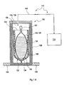
- FIGS. 1A to 1C a first embodiment of a cryocontainer 110 according to the invention is shown.
- Figure 1A An exemplary embodiment of a preparation device 112 according to the invention, which further comprises, in addition to the cryocontainer, a delivery device 114 which can be reversibly coupled to the cryocontainer 110.
- Figures 1B and 1C is alone the cryocontainer 110, which in Figure 1A is shown in sectional view from the side with a lid 116, in perspective views obliquely from above ( FIG. 1 B) and from above ( Figure 1C ) without lid 116 shown.
- the cryogenic container 110 includes a primary reservoir 118 in the form of a flexible film bag 120 with hose connections 122.
- 120 may be configured as a sterilized disposable bag of flexible foil bags, for example, as so-called "standard Flexboy ® bioprocessing bag” Sartorius Stedim Biotech.
- the primary container 118 may be filled via the tube connections 122, which may be designed as sterile connections, with a medium, for example a medicament, a diagnostic agent or a biotechnical active substance.
- the medium is generally indicated by the reference numeral 124 in the figures.
- the cryocontainer 110 comprises an outer container 126, which in this embodiment can be made of a basic framework made of a simple carrier material, for example multilayer corrugated cardboard. This framework also serves as stabilization and insulation.
- the outer container 126 may, as in the FIGS. 1A to 1C represented, for example, be configured substantially parallelepiped, with an inner space 128 and optionally one or more support devices 130 to increase the stability.
- a secondary container 132 introduced in this framework of the outer container 126 is in the in the FIGS. 1A to 1C illustrated embodiment, a secondary container 132 introduced.
- This secondary container 132 is configured open at its upper end in the illustrated embodiment and has an opening 133 through which the flexible film bag 120 of the primary container 118 can be introduced into the secondary container 132.
- the secondary container 132 has in the embodiment an outer shell 134, which is designed to be flexible.
- this outer shell 134 may be an upwardly open one Bag of aluminum foil and / or a metal-clad, for example, aluminum-clad plastic sheet act.
- a spacer element 136 is applied, which simultaneously serves the stiffening and the formation of a heat exchanger space 138 between the outer shell 134 and the flexible foil bag 120 of the primary container 118.
- this spacer element 136 may be made of plastic. This can ensure a separating layer between the insulation, in particular the secondary container 132 or the outer casing 134, and the medium 124. As in particular from Figure 1C it emerges, this spacer element 136 is arranged in the illustrated embodiment, only on the broad sides of the flexible film bag 120, but not on the narrow sides. Again, or only a slight contact between the outer shell 134 and the primary container 118 takes place on these narrow sides.
- the spacer element 136 is set up so that it can receive or flow through a heat exchange medium.
- a heat exchange medium for example liquid nitrogen (LN 2 ) can be added to the space between the outer envelope 134 and the flexible foil bag 120 serving as heat exchanger space 138. This spontaneously evaporates, thus cooling the medium 124.
- the amount of liquid nitrogen can be used to control the process.
- the liquid nitrogen, as in Figure 1A are provided by a supply device 114 via a pipeline system 140, which is not shown in the remaining figures and which can be coupled to the cryocontainer 110 and decoupled from this.
- the entire disposable system of the cryocontainer 110 can be stored, for example, in a Tieccühlraum.
- preheated air is blown into the heat exchanger chamber 138 to thaw and thus reuse the medium 124.
- this can be done for example by means of the provision device 114 or with a similar provision device.
- a passive thawing process can also be used.
- the surrounding air at room temperature may already be sufficient to allow thawing without additional devices and / or without active injection of preheated air into the heat exchanger space 138.
- cryocontainer After use, the cost-effective cryocontainer can be disposed of completely or partially without special cleaning.
- a container tourism, as is usually required in conventional cryogenic containers made of stainless steel, can thus be omitted preferably.
- a flexible film bag 120 for example, commercially available disposables can be used.
- bag volumes up to 50 liters or even 80 liters or more are conceivable.
- multiple sets that is to say cryocontainer 110 with a plurality of primary containers 118, for example in one or more interior spaces 128, are also possible.
- several compartments may be provided.
- one, two, three, four or five flexible foil pouches 120 may be received in a cryocontainer 110.
- a plurality of cryocontainers 110 can be stored on a pallet, for example a Euro pallet.
- up to 300 liters can be stored on a pallet, with halved weight and volume in comparison to conventional cryogenic vessels, in particular made of stainless steel.
- the proposed cryocontainer has proven to be useful for practical use. For example, freezing times for one liter of water of about half an hour have been recorded. Per kilogram of liquid was needed between 1.5 and 2 liters of liquid nitrogen. For example, a predetermined amount of liquid nitrogen, which is just sufficient for a freezing process, be entered into the heat exchanger chamber 138.
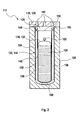
- FIG. 2 is, in analogous representation to FIG. 1 however, without the delivery device 114 and the piping system 140, a second embodiment of a cryocontainer 110 according to the present invention is illustrated.
- this cryocontainer 110 comprises a primary container 118 with a flexible foil bag 120 and hose connectors 122.
- this primary container 118 reference may be made, for example, to the above description FIGS. 1A to 1C to get expelled.
- the cryocontainer 110 in turn comprises an outer container 126, which also has a lid 116.
- This cover 116 is in this case with several feedthroughs 142 equipped, so that an introduction and / or discharge of the heat exchange medium and / or to be stored or transported medium 124 can also be done with the outer container 126 closed.
- the outer container 126 for example, to the above description of FIGS. 1A to 1C to get expelled.
- the cryocontainer 110 also has a secondary container 132, which has a heat exchanger chamber 138.
- the heat exchanger medium according to the embodiment FIG. 2
- the secondary container 132 is configured in the illustrated embodiment with a double-walled receiving bag 144.
- the secondary container 132 in addition to the outer shell 134 in addition to the flexible film bag 120 assigning flexible inner shell 146.
- the outer shell 134 and the inner shell 146 may be welded together, so that forms between the outer shell 134 and the inner shell 146, a heat exchanger chamber 138 in the form of a long, narrow and wide channel, which starts at a first port 148 and at one second port 150 ends.
- the first port 148 may serve as a feed for a heat exchange medium
- the second port 150 as a drain for this heat exchange medium.
- the heat exchange medium from the first port 148 to the second port 150 can flow.
- the spacer element 136 may additionally, in whole or in part, act as a flow straightener to effect a uniform flow, preferably along the entire surface of the heat exchanger space 138.
- the heat exchange medium may be pumped from the first port 148 to the second port 150 through the heat exchanger space 138, for example by means of a corresponding delivery device 114, as shown in FIG Figure 1A .
- a heat exchange medium ie as a heat carrier
- silicone oil can be used for example in this case.
Priority Applications (1)
| Application Number | Priority Date | Filing Date | Title |
|---|---|---|---|
| EP10700495A EP2389063B1 (de) | 2009-01-20 | 2010-01-13 | Kryobehälter |
Applications Claiming Priority (3)
| Application Number | Priority Date | Filing Date | Title |
|---|---|---|---|
| EP09150937 | 2009-01-20 | ||
| EP10700495A EP2389063B1 (de) | 2009-01-20 | 2010-01-13 | Kryobehälter |
| PCT/EP2010/000117 WO2010083951A1 (de) | 2009-01-20 | 2010-01-13 | Kryobehälter |
Publications (2)
| Publication Number | Publication Date |
|---|---|
| EP2389063A1 EP2389063A1 (de) | 2011-11-30 |
| EP2389063B1 true EP2389063B1 (de) | 2012-10-24 |
Family
ID=40656233
Family Applications (1)
| Application Number | Title | Priority Date | Filing Date |
|---|---|---|---|
| EP10700495A Not-in-force EP2389063B1 (de) | 2009-01-20 | 2010-01-13 | Kryobehälter |
Country Status (9)
| Country | Link |
|---|---|
| US (3) | US9920970B2 (zh) |
| EP (1) | EP2389063B1 (zh) |
| JP (1) | JP5460735B2 (zh) |
| CN (1) | CN102291987B (zh) |
| CA (1) | CA2749978A1 (zh) |
| ES (1) | ES2393662T3 (zh) |
| HK (1) | HK1162120A1 (zh) |
| SG (1) | SG173062A1 (zh) |
| WO (1) | WO2010083951A1 (zh) |
Cited By (2)
| Publication number | Priority date | Publication date | Assignee | Title |
|---|---|---|---|---|
| US10722623B2 (en) | 2014-08-08 | 2020-07-28 | Fremon Scientific, Inc. | Smart bag used in sensing physiological and/or physical parameters of bags containing biological substance |
| US10732083B2 (en) | 2018-05-07 | 2020-08-04 | Fremon Scientific, Inc. | Thawing biological substances |
Families Citing this family (29)
| Publication number | Priority date | Publication date | Assignee | Title |
|---|---|---|---|---|
| US8756901B2 (en) * | 2009-12-10 | 2014-06-24 | Vlad Carey | V-pack |
| US20120210734A1 (en) * | 2011-02-22 | 2012-08-23 | Hoffman Gary A | Production and use of high pressure for cryopreservation and cryofixation |
| CA2857256C (en) * | 2012-01-17 | 2020-06-23 | Nico Corporation | System for collecting and preserving tissue cores |
| CN202449398U (zh) * | 2012-02-16 | 2012-09-26 | 弗英(天津)物流系统科技有限公司 | 一种可控温度周转箱 |
| ES2454871B1 (es) * | 2012-09-11 | 2015-03-02 | Need Stephane Espinosa | Dispositivo refrigerador de alimentos sin fuente de energía ni hielo |
| TW201504439A (zh) * | 2013-07-18 | 2015-02-01 | Steminent Biotherapeutics Inc | 血袋漸凍保存裝置及其使用方法 |
| US10001313B2 (en) * | 2013-09-09 | 2018-06-19 | Inovatzia, Inc. | Reusable cryogenic carrying case for biological materials |
| JP2017506097A (ja) | 2014-02-05 | 2017-03-02 | マフィン・インコーポレイテッドMuffin Incorporated | 区画された低温保存容器およびその使用 |
| CN103818650A (zh) * | 2014-02-27 | 2014-05-28 | 青岛朗夫包装有限公司 | 带加热系统的周转箱内衬袋 |
| US10555374B2 (en) * | 2014-05-16 | 2020-02-04 | Biolife Solutions, Inc. | Systems, devices, and methods for automated sample thawing |
| ES2548191B2 (es) * | 2014-06-26 | 2016-02-26 | Enrique GONZÁLEZ BLANCO | Depósito submarino criogénico flexible |
| WO2016167332A1 (ja) * | 2015-04-17 | 2016-10-20 | 国立大学法人大阪大学 | シート状細胞培養物の凍結保存方法 |
| JP6549788B2 (ja) | 2015-10-22 | 2019-07-24 | イー・エム・デイー・ミリポア・コーポレイシヨン | 液体を保管、搬送、および/または取り扱うための装置、ならびに滅菌または無菌液を取り扱う方法 |
| JP6696870B2 (ja) * | 2016-09-23 | 2020-05-20 | 大陽日酸株式会社 | 液体用バッグの急速凍結方法および急速凍結装置 |
| DK3534852T3 (da) * | 2016-11-02 | 2022-03-28 | Miraki Innovation Think Tank Llc | Apparat til frembringelse af en opslæmning |
| US11324673B2 (en) | 2016-11-18 | 2022-05-10 | Miraki Innovation Think Tank Llc | Cosmetic appearance of skin |
| GB201621645D0 (en) * | 2016-12-19 | 2017-02-01 | Asymptote Ltd | Shipping container |
| US10729126B2 (en) | 2017-01-16 | 2020-08-04 | Biolife Solutions, Inc. | Portable thawer components and features |
| AU2018250270A1 (en) | 2017-04-05 | 2019-10-31 | Miraki Innovation Think Tank Llc | Point of delivery cold slurry generation |
| EP3606456A4 (en) | 2017-04-05 | 2021-01-13 | Miraki Innovation Think Tank LLC | COLD THICK SUSPENSION CONTAINMENT |
| US10500342B2 (en) | 2017-08-21 | 2019-12-10 | Miraki Innovation Think Tank Llc | Cold slurry syringe |
| US11352262B2 (en) | 2017-12-18 | 2022-06-07 | Praxair Technology, Inc. | Methods for automatic filling, charging and dispensing carbon dioxide snow block |
| GB201721588D0 (en) | 2017-12-21 | 2018-02-07 | Asymptote Ltd | Container for cryopreserved samples |
| WO2019176765A1 (ja) * | 2018-03-13 | 2019-09-19 | テルモ株式会社 | 融解装置及び融解方法 |
| US20210137787A1 (en) * | 2018-04-11 | 2021-05-13 | Biolife Solutions, Inc. | Systems and Methods for Cryostorage Bag Protection |
| WO2019245976A1 (en) * | 2018-06-18 | 2019-12-26 | Cryoport, Inc. | Cryoliner |
| TWM588696U (zh) * | 2019-08-28 | 2020-01-01 | 阿里山製酒股份有限公司 | 流水調溫發酵槽及其發酵槽循環水溫度控制系統 |
| US11542085B2 (en) * | 2020-04-08 | 2023-01-03 | Biolife Solutions, Inc. | Shock absorbing container to protect cryopreserved biological material |
| CN114852496B (zh) * | 2022-07-05 | 2022-09-09 | 山东第一医科大学附属省立医院(山东省立医院) | 一种心血管科用血液样本存放设备 |
Family Cites Families (40)
| Publication number | Priority date | Publication date | Assignee | Title |
|---|---|---|---|---|
| US1549510A (en) * | 1924-11-26 | 1925-08-11 | Schnitzler Bernhard | Water bag |
| US3006165A (en) * | 1956-10-31 | 1961-10-31 | Masson Paul Inc | Containers |
| US3034305A (en) * | 1959-09-24 | 1962-05-15 | Adir Apparecchi Di Raffreddame | Portable refrigerating unit |
| GB1153472A (en) * | 1965-06-25 | 1969-05-29 | Ralph Kerr Hadden | A Method of, and Apparatus for, the Heating or Cooling of Liquids |
| US3893834A (en) * | 1974-03-04 | 1975-07-08 | Arthur E Armstrong | Insulated cold pack |
| US4049408A (en) * | 1975-03-10 | 1977-09-20 | The Kendall Company | Disposable cold pack for blood specimen |
| US4420097A (en) * | 1981-01-15 | 1983-12-13 | Motsenbocker Gregg A | Portable liquid dispenser with carrying case |
| US4605006A (en) * | 1984-02-28 | 1986-08-12 | Minnesota Mining And Manufacturing Company | Hypothermic protection pad |
| US4723974A (en) * | 1985-07-26 | 1988-02-09 | Ammerman Stephen W | Transporting container for an amputated extremity |
| WO1991003934A1 (en) * | 1989-09-14 | 1991-04-04 | Krasner Paul R | Apparatus and method for preserving and transporting body organs and tissues |
| DE69104773T2 (de) * | 1990-05-21 | 1995-03-02 | Ishikawajima Harima Heavy Ind | Hitzeschutzelement. |
| JPH0753626Y2 (ja) * | 1992-10-23 | 1995-12-13 | 株式会社大塚製薬工場 | 血漿冷却・加温用バッグ |
| US6223551B1 (en) * | 1996-01-29 | 2001-05-01 | Instar Pty. Ltd. | Portable flexible container for keeping articles cold |
| US6065625A (en) * | 1996-05-29 | 2000-05-23 | Converta-Vans, Incorporated | Collapsible tank for convertible freight container |
| US5950450A (en) * | 1996-06-12 | 1999-09-14 | Vacupanel, Inc. | Containment system for transporting and storing temperature-sensitive materials |
| US6083256A (en) * | 1996-08-15 | 2000-07-04 | Der Ovanesian; Mary | NNT or cold pad with inner element |
| AUPP560398A0 (en) | 1998-08-31 | 1998-09-24 | Laby, Ralph Henry | Cool keeping transport arrangement and method |
| US6119465A (en) * | 1999-02-10 | 2000-09-19 | Mullens; Patrick L. | Shipping container for storing materials at cryogenic temperatures |
| US6301961B1 (en) * | 1999-08-26 | 2001-10-16 | Patrick J. Rolfes | Insulated beverage carafe with volume indicator |
| DE10024909A1 (de) | 2000-05-19 | 2001-12-06 | Messer Griesheim Gmbh | Vorrichtung zur Transferdruckgaserzeugung in Behältern für kryogene Flüssigkeiten |
| US6739112B1 (en) * | 2000-08-21 | 2004-05-25 | Nu Vasive, Inc. | Bone allograft packaging system |
| JP2002068324A (ja) * | 2000-08-30 | 2002-03-08 | Nippon Sanso Corp | 断熱容器 |
| US6422032B1 (en) * | 2001-01-24 | 2002-07-23 | Gary Keith Greene | Reusable cooler bag |
| US6612125B1 (en) * | 2001-03-14 | 2003-09-02 | Yul Gevargis | Solar evaporating cooling system |
| DE10151343A1 (de) * | 2001-10-22 | 2003-05-08 | Vita 34 Ag | Beutelsystem für die Kryokonservierung von Körperflüssigkeiten |
| US7104074B2 (en) * | 2001-11-01 | 2006-09-12 | Integrated Biosystems, Inc. | Systems and methods for freezing, storing, transporting and thawing biopharmaceutical material |
| JP2005507692A (ja) * | 2001-11-01 | 2005-03-24 | インテグレイテッド バイオシステムズ,インコーポレイテッド | 生物薬剤材料を凍結及び貯蔵するためのシステム、及びその方法 |
| JP3792595B2 (ja) | 2002-04-01 | 2006-07-05 | 株式会社川崎造船 | 極低温タンク用防熱構造 |
| US6668579B1 (en) * | 2002-06-06 | 2003-12-30 | Mpdi | Container with refillable core |
| US6655156B1 (en) * | 2002-08-28 | 2003-12-02 | Cortec Corporation | Biodegradable cryogenic bag |
| US6708502B1 (en) * | 2002-09-27 | 2004-03-23 | The Regents Of The University Of California | Lightweight cryogenic-compatible pressure vessels for vehicular fuel storage |
| DE102004001805B3 (de) * | 2004-01-06 | 2005-06-02 | Siemens Ag | Evakuierbarer Isolierbehälter für eine zu kühlende Anwendung |
| US7096686B2 (en) * | 2004-03-04 | 2006-08-29 | Follett Corporation | Ice making apparatus |
| AU2005323451B2 (en) * | 2004-05-21 | 2010-11-18 | Qiagen Sciences Llc | Kits and processes for removing contaminants from nucleic acids in environmental and biological samples |
| EP1621178A1 (en) * | 2004-07-29 | 2006-02-01 | Fresenius Kabi Deutschland GmbH | Flexible multi-chamber container for the preparation of medical mixed solutions |
| US7464567B1 (en) * | 2005-05-17 | 2008-12-16 | Crossley Rita J | Apparatus for cooling and dispensing wine |
| US7641068B2 (en) * | 2005-09-26 | 2010-01-05 | Gm Global Technology Operations, Inc. | Liquid hydrogen storage tank with common-access tube as port for pipes into the inner vessel |
| EP1959187B1 (en) | 2007-02-16 | 2012-07-25 | Nexans | Electric fault current limiter having superconducting elements inside a cryogenic vessel and bushings for connecting an external circuit |
| US8100284B2 (en) | 2007-02-16 | 2012-01-24 | GM Global Technology Opertions LLC | Cryogenic storage tank with thermal shield |
| US7896199B2 (en) * | 2007-05-01 | 2011-03-01 | Daniel Steven Kaczmarek | Portable liquid-dispensing bag |
-
2010
- 2010-01-13 ES ES10700495T patent/ES2393662T3/es active Active
- 2010-01-13 CA CA2749978A patent/CA2749978A1/en not_active Abandoned
- 2010-01-13 CN CN201080005430.2A patent/CN102291987B/zh not_active Expired - Fee Related
- 2010-01-13 SG SG2011052347A patent/SG173062A1/en unknown
- 2010-01-13 WO PCT/EP2010/000117 patent/WO2010083951A1/de active Application Filing
- 2010-01-13 JP JP2011545671A patent/JP5460735B2/ja not_active Expired - Fee Related
- 2010-01-13 EP EP10700495A patent/EP2389063B1/de not_active Not-in-force
-
2011
- 2011-07-14 US US13/183,045 patent/US9920970B2/en active Active
-
2012
- 2012-03-13 HK HK12102530.9A patent/HK1162120A1/zh not_active IP Right Cessation
-
2018
- 2018-01-31 US US15/884,569 patent/US10174985B2/en not_active Expired - Fee Related
- 2018-12-04 US US16/209,037 patent/US10935298B2/en active Active
Cited By (6)
| Publication number | Priority date | Publication date | Assignee | Title |
|---|---|---|---|---|
| US10722623B2 (en) | 2014-08-08 | 2020-07-28 | Fremon Scientific, Inc. | Smart bag used in sensing physiological and/or physical parameters of bags containing biological substance |
| US10732083B2 (en) | 2018-05-07 | 2020-08-04 | Fremon Scientific, Inc. | Thawing biological substances |
| US10816446B2 (en) | 2018-05-07 | 2020-10-27 | Fremon Scientific, Inc. | Thawing biological substances |
| US10837885B2 (en) | 2018-05-07 | 2020-11-17 | Fremon Scientific, Inc. | Thawing biological substances |
| US10866173B2 (en) | 2018-05-07 | 2020-12-15 | Fremon Scientific, Inc. | Thawing biological substances |
| US11448575B2 (en) | 2018-05-07 | 2022-09-20 | Fremon Scientific, Inc. | Thawing biological substances |
Also Published As
| Publication number | Publication date |
|---|---|
| CN102291987B (zh) | 2014-07-30 |
| EP2389063A1 (de) | 2011-11-30 |
| WO2010083951A1 (de) | 2010-07-29 |
| US20110309086A1 (en) | 2011-12-22 |
| US10174985B2 (en) | 2019-01-08 |
| ES2393662T3 (es) | 2012-12-27 |
| JP2012515688A (ja) | 2012-07-12 |
| SG173062A1 (en) | 2011-08-29 |
| HK1162120A1 (zh) | 2012-08-24 |
| JP5460735B2 (ja) | 2014-04-02 |
| US9920970B2 (en) | 2018-03-20 |
| CN102291987A (zh) | 2011-12-21 |
| CA2749978A1 (en) | 2010-07-29 |
| US20190107316A1 (en) | 2019-04-11 |
| US20180149401A1 (en) | 2018-05-31 |
| US10935298B2 (en) | 2021-03-02 |
Similar Documents
| Publication | Publication Date | Title |
|---|---|---|
| EP2389063B1 (de) | Kryobehälter | |
| EP2943414B1 (de) | Modularer isolierbehälter und verfahren zum betreiben eines solchen | |
| DE202019104570U1 (de) | Transportbehälter | |
| WO2017055280A1 (de) | Thermoschutzspeicherzelle einer kühltransportbox | |
| DE102012006743B4 (de) | Isolierbehälter | |
| EP2252331A1 (de) | Transfercontainer für pharmazeutische behältnisse | |
| WO2001067013A1 (de) | Aufbewahr- und transportbehälter für leicht verderbliche produkte | |
| EP2268178B1 (de) | Isolationsbehälter mit innenbehälter für flüssigkeiten | |
| WO2010015232A1 (de) | Verfahren und vorrichtung zum transfer einer substanz zwischen geschlossenen systemen | |
| EP2174880B1 (de) | Einrichtung zur Aufnahme von Behältern und zugehöriger Container | |
| WO2019110146A1 (de) | Transportbehälter mit kühlbarem, thermischen schild | |
| DE102014117658A1 (de) | Mischvorrichtung mit Strömungsbrecher | |
| DE202007012289U1 (de) | Modulare, isolierende Transportbehälter | |
| DE102005050668B4 (de) | Modular aufgebaute Vorrichtung für Transport und/oder Lagerung temperaturempfindlicher Waren | |
| WO2003093740A1 (de) | Transportbehälter für biologisches material | |
| WO2010089317A2 (de) | Tank | |
| DE3320349A1 (de) | Transportabler tiefkuehlbehaelter zum gefrieren von packungen mit insbesondere biomedizinischen fluessigkeiten | |
| EP2938365B1 (de) | Begehbare stationäre ethylenoxid-sterilisationsanlage | |
| DE102007034132B4 (de) | Perfusionsbeutel für explantierte Organe und Organteile | |
| DE102011116693B4 (de) | Kühlvorrichtung | |
| DE1601899C (de) | Luftfracht Kühlbehälter | |
| EP3755394A1 (de) | Vorrichtung enthaltend eine dialyselösung | |
| DE102017119788A1 (de) | Kühlelementhülle für ein Trockeneismodul | |
| DE102007023198A1 (de) | Magazin für zylindrische Gefässe | |
| DE202011051284U1 (de) | Klappbarer Transportbehälter mit Kühlelementen |
Legal Events
| Date | Code | Title | Description |
|---|---|---|---|
| PUAI | Public reference made under article 153(3) epc to a published international application that has entered the european phase |
Free format text: ORIGINAL CODE: 0009012 |
|
| 17P | Request for examination filed |
Effective date: 20110811 |
|
| AK | Designated contracting states |
Kind code of ref document: A1 Designated state(s): AT BE BG CH CY CZ DE DK EE ES FI FR GB GR HR HU IE IS IT LI LT LU LV MC MK MT NL NO PL PT RO SE SI SK SM TR |
|
| DAX | Request for extension of the european patent (deleted) | ||
| REG | Reference to a national code |
Ref country code: DE Ref legal event code: R079 Ref document number: 502010001504 Country of ref document: DE Free format text: PREVIOUS MAIN CLASS: A01N0001000000 Ipc: F25D0025000000 |
|
| RIC1 | Information provided on ipc code assigned before grant |
Ipc: A01N 1/02 20060101ALI20120510BHEP Ipc: A01N 1/00 20060101ALI20120510BHEP Ipc: F25D 25/00 20060101AFI20120510BHEP Ipc: F25D 3/10 20060101ALI20120510BHEP |
|
| GRAP | Despatch of communication of intention to grant a patent |
Free format text: ORIGINAL CODE: EPIDOSNIGR1 |
|
| GRAS | Grant fee paid |
Free format text: ORIGINAL CODE: EPIDOSNIGR3 |
|
| GRAA | (expected) grant |
Free format text: ORIGINAL CODE: 0009210 |
|
| AK | Designated contracting states |
Kind code of ref document: B1 Designated state(s): AT BE BG CH CY CZ DE DK EE ES FI FR GB GR HR HU IE IS IT LI LT LU LV MC MK MT NL NO PL PT RO SE SI SK SM TR |
|
| REG | Reference to a national code |
Ref country code: GB Ref legal event code: FG4D Free format text: NOT ENGLISH |
|
| REG | Reference to a national code |
Ref country code: CH Ref legal event code: NV Representative=s name: BOHEST AG Ref country code: CH Ref legal event code: EP |
|
| REG | Reference to a national code |
Ref country code: AT Ref legal event code: REF Ref document number: 581160 Country of ref document: AT Kind code of ref document: T Effective date: 20121115 |
|
| REG | Reference to a national code |
Ref country code: IE Ref legal event code: FG4D Free format text: LANGUAGE OF EP DOCUMENT: GERMAN |
|
| REG | Reference to a national code |
Ref country code: DE Ref legal event code: R096 Ref document number: 502010001504 Country of ref document: DE Effective date: 20121220 |
|
| REG | Reference to a national code |
Ref country code: ES Ref legal event code: FG2A Ref document number: 2393662 Country of ref document: ES Kind code of ref document: T3 Effective date: 20121227 |
|
| REG | Reference to a national code |
Ref country code: NL Ref legal event code: VDEP Effective date: 20121024 |
|
| PG25 | Lapsed in a contracting state [announced via postgrant information from national office to epo] |
Ref country code: IS Free format text: LAPSE BECAUSE OF FAILURE TO SUBMIT A TRANSLATION OF THE DESCRIPTION OR TO PAY THE FEE WITHIN THE PRESCRIBED TIME-LIMIT Effective date: 20130224 Ref country code: HR Free format text: LAPSE BECAUSE OF FAILURE TO SUBMIT A TRANSLATION OF THE DESCRIPTION OR TO PAY THE FEE WITHIN THE PRESCRIBED TIME-LIMIT Effective date: 20121024 Ref country code: NL Free format text: LAPSE BECAUSE OF FAILURE TO SUBMIT A TRANSLATION OF THE DESCRIPTION OR TO PAY THE FEE WITHIN THE PRESCRIBED TIME-LIMIT Effective date: 20121024 Ref country code: SE Free format text: LAPSE BECAUSE OF FAILURE TO SUBMIT A TRANSLATION OF THE DESCRIPTION OR TO PAY THE FEE WITHIN THE PRESCRIBED TIME-LIMIT Effective date: 20121024 Ref country code: FI Free format text: LAPSE BECAUSE OF FAILURE TO SUBMIT A TRANSLATION OF THE DESCRIPTION OR TO PAY THE FEE WITHIN THE PRESCRIBED TIME-LIMIT Effective date: 20121024 Ref country code: NO Free format text: LAPSE BECAUSE OF FAILURE TO SUBMIT A TRANSLATION OF THE DESCRIPTION OR TO PAY THE FEE WITHIN THE PRESCRIBED TIME-LIMIT Effective date: 20130124 |
|
| PG25 | Lapsed in a contracting state [announced via postgrant information from national office to epo] |
Ref country code: PL Free format text: LAPSE BECAUSE OF FAILURE TO SUBMIT A TRANSLATION OF THE DESCRIPTION OR TO PAY THE FEE WITHIN THE PRESCRIBED TIME-LIMIT Effective date: 20121024 Ref country code: SI Free format text: LAPSE BECAUSE OF FAILURE TO SUBMIT A TRANSLATION OF THE DESCRIPTION OR TO PAY THE FEE WITHIN THE PRESCRIBED TIME-LIMIT Effective date: 20121024 Ref country code: PT Free format text: LAPSE BECAUSE OF FAILURE TO SUBMIT A TRANSLATION OF THE DESCRIPTION OR TO PAY THE FEE WITHIN THE PRESCRIBED TIME-LIMIT Effective date: 20130225 Ref country code: GR Free format text: LAPSE BECAUSE OF FAILURE TO SUBMIT A TRANSLATION OF THE DESCRIPTION OR TO PAY THE FEE WITHIN THE PRESCRIBED TIME-LIMIT Effective date: 20130125 Ref country code: LV Free format text: LAPSE BECAUSE OF FAILURE TO SUBMIT A TRANSLATION OF THE DESCRIPTION OR TO PAY THE FEE WITHIN THE PRESCRIBED TIME-LIMIT Effective date: 20121024 |
|
| BERE | Be: lapsed |
Owner name: F. HOFFMANN-LA ROCHE A.G. Effective date: 20130131 |
|
| PG25 | Lapsed in a contracting state [announced via postgrant information from national office to epo] |
Ref country code: BG Free format text: LAPSE BECAUSE OF FAILURE TO SUBMIT A TRANSLATION OF THE DESCRIPTION OR TO PAY THE FEE WITHIN THE PRESCRIBED TIME-LIMIT Effective date: 20130124 Ref country code: CZ Free format text: LAPSE BECAUSE OF FAILURE TO SUBMIT A TRANSLATION OF THE DESCRIPTION OR TO PAY THE FEE WITHIN THE PRESCRIBED TIME-LIMIT Effective date: 20121024 Ref country code: DK Free format text: LAPSE BECAUSE OF FAILURE TO SUBMIT A TRANSLATION OF THE DESCRIPTION OR TO PAY THE FEE WITHIN THE PRESCRIBED TIME-LIMIT Effective date: 20121024 Ref country code: EE Free format text: LAPSE BECAUSE OF FAILURE TO SUBMIT A TRANSLATION OF THE DESCRIPTION OR TO PAY THE FEE WITHIN THE PRESCRIBED TIME-LIMIT Effective date: 20121024 Ref country code: SK Free format text: LAPSE BECAUSE OF FAILURE TO SUBMIT A TRANSLATION OF THE DESCRIPTION OR TO PAY THE FEE WITHIN THE PRESCRIBED TIME-LIMIT Effective date: 20121024 |
|
| PG25 | Lapsed in a contracting state [announced via postgrant information from national office to epo] |
Ref country code: RO Free format text: LAPSE BECAUSE OF FAILURE TO SUBMIT A TRANSLATION OF THE DESCRIPTION OR TO PAY THE FEE WITHIN THE PRESCRIBED TIME-LIMIT Effective date: 20121024 Ref country code: MC Free format text: LAPSE BECAUSE OF NON-PAYMENT OF DUE FEES Effective date: 20130131 |
|
| PLBE | No opposition filed within time limit |
Free format text: ORIGINAL CODE: 0009261 |
|
| STAA | Information on the status of an ep patent application or granted ep patent |
Free format text: STATUS: NO OPPOSITION FILED WITHIN TIME LIMIT |
|
| 26N | No opposition filed |
Effective date: 20130725 |
|
| REG | Reference to a national code |
Ref country code: IE Ref legal event code: MM4A |
|
| PG25 | Lapsed in a contracting state [announced via postgrant information from national office to epo] |
Ref country code: BE Free format text: LAPSE BECAUSE OF NON-PAYMENT OF DUE FEES Effective date: 20130131 |
|
| REG | Reference to a national code |
Ref country code: DE Ref legal event code: R097 Ref document number: 502010001504 Country of ref document: DE Effective date: 20130725 |
|
| PG25 | Lapsed in a contracting state [announced via postgrant information from national office to epo] |
Ref country code: CY Free format text: LAPSE BECAUSE OF FAILURE TO SUBMIT A TRANSLATION OF THE DESCRIPTION OR TO PAY THE FEE WITHIN THE PRESCRIBED TIME-LIMIT Effective date: 20121024 |
|
| PG25 | Lapsed in a contracting state [announced via postgrant information from national office to epo] |
Ref country code: IE Free format text: LAPSE BECAUSE OF NON-PAYMENT OF DUE FEES Effective date: 20130113 |
|
| PG25 | Lapsed in a contracting state [announced via postgrant information from national office to epo] |
Ref country code: LT Free format text: LAPSE BECAUSE OF FAILURE TO SUBMIT A TRANSLATION OF THE DESCRIPTION OR TO PAY THE FEE WITHIN THE PRESCRIBED TIME-LIMIT Effective date: 20121024 Ref country code: MT Free format text: LAPSE BECAUSE OF FAILURE TO SUBMIT A TRANSLATION OF THE DESCRIPTION OR TO PAY THE FEE WITHIN THE PRESCRIBED TIME-LIMIT Effective date: 20121024 |
|
| REG | Reference to a national code |
Ref country code: CH Ref legal event code: PCAR Free format text: NEW ADDRESS: HOLBEINSTRASSE 36-38, 4051 BASEL (CH) |
|
| PG25 | Lapsed in a contracting state [announced via postgrant information from national office to epo] |
Ref country code: SM Free format text: LAPSE BECAUSE OF FAILURE TO SUBMIT A TRANSLATION OF THE DESCRIPTION OR TO PAY THE FEE WITHIN THE PRESCRIBED TIME-LIMIT Effective date: 20121024 |
|
| PG25 | Lapsed in a contracting state [announced via postgrant information from national office to epo] |
Ref country code: TR Free format text: LAPSE BECAUSE OF FAILURE TO SUBMIT A TRANSLATION OF THE DESCRIPTION OR TO PAY THE FEE WITHIN THE PRESCRIBED TIME-LIMIT Effective date: 20121024 |
|
| PG25 | Lapsed in a contracting state [announced via postgrant information from national office to epo] |
Ref country code: LU Free format text: LAPSE BECAUSE OF NON-PAYMENT OF DUE FEES Effective date: 20130113 Ref country code: HU Free format text: LAPSE BECAUSE OF FAILURE TO SUBMIT A TRANSLATION OF THE DESCRIPTION OR TO PAY THE FEE WITHIN THE PRESCRIBED TIME-LIMIT; INVALID AB INITIO Effective date: 20100113 Ref country code: MK Free format text: LAPSE BECAUSE OF FAILURE TO SUBMIT A TRANSLATION OF THE DESCRIPTION OR TO PAY THE FEE WITHIN THE PRESCRIBED TIME-LIMIT Effective date: 20121024 |
|
| REG | Reference to a national code |
Ref country code: FR Ref legal event code: PLFP Year of fee payment: 7 |
|
| REG | Reference to a national code |
Ref country code: AT Ref legal event code: MM01 Ref document number: 581160 Country of ref document: AT Kind code of ref document: T Effective date: 20150113 |
|
| PG25 | Lapsed in a contracting state [announced via postgrant information from national office to epo] |
Ref country code: AT Free format text: LAPSE BECAUSE OF NON-PAYMENT OF DUE FEES Effective date: 20150113 |
|
| REG | Reference to a national code |
Ref country code: FR Ref legal event code: PLFP Year of fee payment: 8 |
|
| REG | Reference to a national code |
Ref country code: FR Ref legal event code: PLFP Year of fee payment: 9 |
|
| PGFP | Annual fee paid to national office [announced via postgrant information from national office to epo] |
Ref country code: ES Payment date: 20180213 Year of fee payment: 9 |
|
| PGFP | Annual fee paid to national office [announced via postgrant information from national office to epo] |
Ref country code: IT Payment date: 20180131 Year of fee payment: 9 |
|
| PG25 | Lapsed in a contracting state [announced via postgrant information from national office to epo] |
Ref country code: IT Free format text: LAPSE BECAUSE OF NON-PAYMENT OF DUE FEES Effective date: 20190113 |
|
| REG | Reference to a national code |
Ref country code: ES Ref legal event code: FD2A Effective date: 20200309 |
|
| PG25 | Lapsed in a contracting state [announced via postgrant information from national office to epo] |
Ref country code: ES Free format text: LAPSE BECAUSE OF NON-PAYMENT OF DUE FEES Effective date: 20190114 |
|
| PGFP | Annual fee paid to national office [announced via postgrant information from national office to epo] |
Ref country code: CH Payment date: 20210121 Year of fee payment: 12 Ref country code: FR Payment date: 20210126 Year of fee payment: 12 |
|
| PGFP | Annual fee paid to national office [announced via postgrant information from national office to epo] |
Ref country code: DE Payment date: 20210127 Year of fee payment: 12 Ref country code: GB Payment date: 20210125 Year of fee payment: 12 |
|
| REG | Reference to a national code |
Ref country code: DE Ref legal event code: R119 Ref document number: 502010001504 Country of ref document: DE |
|
| REG | Reference to a national code |
Ref country code: CH Ref legal event code: PL |
|
| GBPC | Gb: european patent ceased through non-payment of renewal fee |
Effective date: 20220113 |
|
| PG25 | Lapsed in a contracting state [announced via postgrant information from national office to epo] |
Ref country code: GB Free format text: LAPSE BECAUSE OF NON-PAYMENT OF DUE FEES Effective date: 20220113 Ref country code: DE Free format text: LAPSE BECAUSE OF NON-PAYMENT OF DUE FEES Effective date: 20220802 |
|
| PG25 | Lapsed in a contracting state [announced via postgrant information from national office to epo] |
Ref country code: FR Free format text: LAPSE BECAUSE OF NON-PAYMENT OF DUE FEES Effective date: 20220131 |
|
| PG25 | Lapsed in a contracting state [announced via postgrant information from national office to epo] |
Ref country code: LI Free format text: LAPSE BECAUSE OF NON-PAYMENT OF DUE FEES Effective date: 20220131 Ref country code: CH Free format text: LAPSE BECAUSE OF NON-PAYMENT OF DUE FEES Effective date: 20220131 |