EP2386366B1 - Verfahren und Vorrichtung zur kontinuierlichen Erfassung des Schlackenniveaus in Elektroschlacke-Umschmelzanlagen mit kurzen Gleitkokillen - Google Patents
Verfahren und Vorrichtung zur kontinuierlichen Erfassung des Schlackenniveaus in Elektroschlacke-Umschmelzanlagen mit kurzen Gleitkokillen Download PDFInfo
- Publication number
- EP2386366B1 EP2386366B1 EP11156928.1A EP11156928A EP2386366B1 EP 2386366 B1 EP2386366 B1 EP 2386366B1 EP 11156928 A EP11156928 A EP 11156928A EP 2386366 B1 EP2386366 B1 EP 2386366B1
- Authority
- EP
- European Patent Office
- Prior art keywords
- level
- slag bath
- radar
- slag
- measuring probe
- Prior art date
- Legal status (The legal status is an assumption and is not a legal conclusion. Google has not performed a legal analysis and makes no representation as to the accuracy of the status listed.)
- Not-in-force
Links
- 239000002893 slag Substances 0.000 title claims description 46
- 238000000034 method Methods 0.000 title claims description 20
- 238000001514 detection method Methods 0.000 title description 2
- 238000002844 melting Methods 0.000 title description 2
- 230000008018 melting Effects 0.000 title description 2
- 230000000712 assembly Effects 0.000 title 1
- 238000000429 assembly Methods 0.000 title 1
- 239000000523 sample Substances 0.000 claims description 9
- 230000001681 protective effect Effects 0.000 claims description 8
- 238000009434 installation Methods 0.000 claims description 5
- 238000011156 evaluation Methods 0.000 claims description 3
- 230000001960 triggered effect Effects 0.000 claims 1
- XEEYBQQBJWHFJM-UHFFFAOYSA-N Iron Chemical compound [Fe] XEEYBQQBJWHFJM-UHFFFAOYSA-N 0.000 description 6
- PXHVJJICTQNCMI-UHFFFAOYSA-N Nickel Chemical compound [Ni] PXHVJJICTQNCMI-UHFFFAOYSA-N 0.000 description 6
- 229910052751 metal Inorganic materials 0.000 description 6
- 239000002184 metal Substances 0.000 description 6
- 239000007789 gas Substances 0.000 description 5
- 238000007654 immersion Methods 0.000 description 3
- 229910052742 iron Inorganic materials 0.000 description 3
- 229910000595 mu-metal Inorganic materials 0.000 description 3
- 229910052759 nickel Inorganic materials 0.000 description 3
- 229910045601 alloy Inorganic materials 0.000 description 2
- 239000000956 alloy Substances 0.000 description 2
- 238000005266 casting Methods 0.000 description 2
- 238000005259 measurement Methods 0.000 description 2
- 230000000007 visual effect Effects 0.000 description 2
- 229910000838 Al alloy Inorganic materials 0.000 description 1
- RYGMFSIKBFXOCR-UHFFFAOYSA-N Copper Chemical compound [Cu] RYGMFSIKBFXOCR-UHFFFAOYSA-N 0.000 description 1
- 229910000881 Cu alloy Inorganic materials 0.000 description 1
- FYYHWMGAXLPEAU-UHFFFAOYSA-N Magnesium Chemical compound [Mg] FYYHWMGAXLPEAU-UHFFFAOYSA-N 0.000 description 1
- 229910000861 Mg alloy Inorganic materials 0.000 description 1
- ZOKXTWBITQBERF-UHFFFAOYSA-N Molybdenum Chemical compound [Mo] ZOKXTWBITQBERF-UHFFFAOYSA-N 0.000 description 1
- 229910000831 Steel Inorganic materials 0.000 description 1
- XAGFODPZIPBFFR-UHFFFAOYSA-N aluminium Chemical compound [Al] XAGFODPZIPBFFR-UHFFFAOYSA-N 0.000 description 1
- 230000005540 biological transmission Effects 0.000 description 1
- 239000010941 cobalt Substances 0.000 description 1
- 229910017052 cobalt Inorganic materials 0.000 description 1
- GUTLYIVDDKVIGB-UHFFFAOYSA-N cobalt atom Chemical compound [Co] GUTLYIVDDKVIGB-UHFFFAOYSA-N 0.000 description 1
- 238000001816 cooling Methods 0.000 description 1
- 229910052802 copper Inorganic materials 0.000 description 1
- 239000010949 copper Substances 0.000 description 1
- 230000000694 effects Effects 0.000 description 1
- 230000005672 electromagnetic field Effects 0.000 description 1
- 238000002474 experimental method Methods 0.000 description 1
- 238000011010 flushing procedure Methods 0.000 description 1
- 239000011261 inert gas Substances 0.000 description 1
- 239000011777 magnesium Substances 0.000 description 1
- 238000004519 manufacturing process Methods 0.000 description 1
- 239000000463 material Substances 0.000 description 1
- 229910001092 metal group alloy Inorganic materials 0.000 description 1
- 229910052750 molybdenum Inorganic materials 0.000 description 1
- 239000011733 molybdenum Substances 0.000 description 1
- 238000012544 monitoring process Methods 0.000 description 1
- 230000035699 permeability Effects 0.000 description 1
- 238000010926 purge Methods 0.000 description 1
- 239000010959 steel Substances 0.000 description 1
- 238000011179 visual inspection Methods 0.000 description 1
- XLYOFNOQVPJJNP-UHFFFAOYSA-N water Substances O XLYOFNOQVPJJNP-UHFFFAOYSA-N 0.000 description 1
Images


Classifications
-
- B—PERFORMING OPERATIONS; TRANSPORTING
- B22—CASTING; POWDER METALLURGY
- B22D—CASTING OF METALS; CASTING OF OTHER SUBSTANCES BY THE SAME PROCESSES OR DEVICES
- B22D2/00—Arrangement of indicating or measuring devices, e.g. for temperature or viscosity of the fused mass
- B22D2/003—Arrangement of indicating or measuring devices, e.g. for temperature or viscosity of the fused mass for the level of the molten metal
-
- B—PERFORMING OPERATIONS; TRANSPORTING
- B22—CASTING; POWDER METALLURGY
- B22D—CASTING OF METALS; CASTING OF OTHER SUBSTANCES BY THE SAME PROCESSES OR DEVICES
- B22D11/00—Continuous casting of metals, i.e. casting in indefinite lengths
- B22D11/16—Controlling or regulating processes or operations
- B22D11/18—Controlling or regulating processes or operations for pouring
- B22D11/181—Controlling or regulating processes or operations for pouring responsive to molten metal level or slag level
-
- B—PERFORMING OPERATIONS; TRANSPORTING
- B22—CASTING; POWDER METALLURGY
- B22D—CASTING OF METALS; CASTING OF OTHER SUBSTANCES BY THE SAME PROCESSES OR DEVICES
- B22D11/00—Continuous casting of metals, i.e. casting in indefinite lengths
- B22D11/16—Controlling or regulating processes or operations
- B22D11/20—Controlling or regulating processes or operations for removing cast stock
- B22D11/201—Controlling or regulating processes or operations for removing cast stock responsive to molten metal level or slag level
-
- B—PERFORMING OPERATIONS; TRANSPORTING
- B22—CASTING; POWDER METALLURGY
- B22D—CASTING OF METALS; CASTING OF OTHER SUBSTANCES BY THE SAME PROCESSES OR DEVICES
- B22D23/00—Casting processes not provided for in groups B22D1/00 - B22D21/00
- B22D23/06—Melting-down metal, e.g. metal particles, in the mould
- B22D23/10—Electroslag casting
-
- C—CHEMISTRY; METALLURGY
- C22—METALLURGY; FERROUS OR NON-FERROUS ALLOYS; TREATMENT OF ALLOYS OR NON-FERROUS METALS
- C22B—PRODUCTION AND REFINING OF METALS; PRETREATMENT OF RAW MATERIALS
- C22B9/00—General processes of refining or remelting of metals; Apparatus for electroslag or arc remelting of metals
- C22B9/16—Remelting metals
- C22B9/18—Electroslag remelting
-
- G—PHYSICS
- G01—MEASURING; TESTING
- G01F—MEASURING VOLUME, VOLUME FLOW, MASS FLOW OR LIQUID LEVEL; METERING BY VOLUME
- G01F23/00—Indicating or measuring liquid level or level of fluent solid material, e.g. indicating in terms of volume or indicating by means of an alarm
- G01F23/22—Indicating or measuring liquid level or level of fluent solid material, e.g. indicating in terms of volume or indicating by means of an alarm by measuring physical variables, other than linear dimensions, pressure or weight, dependent on the level to be measured, e.g. by difference of heat transfer of steam or water
- G01F23/28—Indicating or measuring liquid level or level of fluent solid material, e.g. indicating in terms of volume or indicating by means of an alarm by measuring physical variables, other than linear dimensions, pressure or weight, dependent on the level to be measured, e.g. by difference of heat transfer of steam or water by measuring the variations of parameters of electromagnetic or acoustic waves applied directly to the liquid or fluent solid material
- G01F23/284—Electromagnetic waves
-
- G—PHYSICS
- G01—MEASURING; TESTING
- G01S—RADIO DIRECTION-FINDING; RADIO NAVIGATION; DETERMINING DISTANCE OR VELOCITY BY USE OF RADIO WAVES; LOCATING OR PRESENCE-DETECTING BY USE OF THE REFLECTION OR RERADIATION OF RADIO WAVES; ANALOGOUS ARRANGEMENTS USING OTHER WAVES
- G01S13/00—Systems using the reflection or reradiation of radio waves, e.g. radar systems; Analogous systems using reflection or reradiation of waves whose nature or wavelength is irrelevant or unspecified
- G01S13/88—Radar or analogous systems specially adapted for specific applications
Definitions
- the level of the slag level that is, the level of the molten metal level
- the level of the slag level be approximately constant with respect to the upper edge of the water-cooled mold, to avoid thermal overload or damage to the system.
- this is achieved by drawing off the remelted melt block continuously or stepwise either from a mold installed in a stationary position downwards, or by withdrawing the mold upwards with a melting block built up on a fixed floor slab becomes.
- From the DE 30 03 082 A1 is a method or apparatus for electroslag remelting in short Gleitkokillen according to the preamble of claims 1 and 3 known.
- the measuring device used there uses an electrical circuit using electro-technical parameters for detecting the level of the surface of the slag bath.
- the invention is a process for the continuous control of slag levels in ESC plants with short planing molds with the characteristic features of continuous measurement of slag level with respect to the upper edge of the mold, by means of a known radar probe incorporated into the mold or protective hood, by a radar beam aimed essentially vertically at the slag surface and the use of the signal obtained for the automatic control of the sluice in such a way that the position of the slag remains constant in the mold or varies within certain limits.
- the procedure according to the invention makes it possible to immediately detect abrupt and marked changes in the slag level and to trigger an alarm or to automatically initiate corrective measures by means of a higher-level controller.
- the signal obtained can be used as an input signal for the control of the block discharge from the mold or in the event of abrupt and marked changes in the level of the slag or when exceeding or falling below certain limits for the triggering of an alarm.
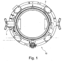
- FIG. 1 is an example of a possible arrangement of a concealed Radarmeßsonde 3 shown in a water-cooled Schirmungsgephase 1, which is flanged to a likewise water-cooled Kokillendeckel 2 an ESU system 10 in plan view.
- Fig. 2 is a plan view in a partially sectioned view of the chimney 2 flanged Schirmungsgephaseuse 1 with a Radarmesssonde 3 and a guided above the Kokilleninnenraums, curved measuring tube 4 with a flushing connection 5 for a gas purging and an indicated line 6 for a power supply of Radarmesssonde. 3 and the transmission of measurement signals.
- the line 6 is connected to an evaluation unit 15 which displays or represents the level of the surface 11 determined by the radar probe 3.
- the line 6 may also be connected to a control device 20 of the ESU system 10.
- the controller 20 either keeps the level of the surface 11 of the slag bath 9 constant or periodically selectively fluctuates within predetermined limits.
- the control device 20 may be connected to an alarm device 21, which triggers an alarm when exceeding or falling below the limits of the level of the surface (11).
- the Fig. 3 shows a vertical section through the Schirmungsgephaseouse 1 with the Radarmesssonde 3 and the curved measuring tube 4, which merges into a conical horn antenna 7. It can be seen further an inner wall 8 of the water-cooled Gleitkokille 13 and the surface 11 of the slag bath 9 (metal mirror). Also indicated is a radar beam 12 generated by the radar probe 3, which preferably impinges on the surface 11 at least approximately perpendicularly.
- the Schirmungsgepuruse 1 is designed in the illustrated embodiment as a double jacket housing, and allows water cooling.
- the shielding housing 1 may additionally be optionally provided with a MU metal layer to shield electromagnetic fields.
- Under a MU metal layer is understood to be a soft metal alloy having a relatively high permeability.
- the MU metal layer may contain about 75-80% nickel, 15% iron and about 3-4% copper, cobalt and / or molybdenum.
Landscapes
- Engineering & Computer Science (AREA)
- Physics & Mathematics (AREA)
- Mechanical Engineering (AREA)
- Electromagnetism (AREA)
- Remote Sensing (AREA)
- Radar, Positioning & Navigation (AREA)
- General Physics & Mathematics (AREA)
- Chemical & Material Sciences (AREA)
- Manufacturing & Machinery (AREA)
- Materials Engineering (AREA)
- Metallurgy (AREA)
- Organic Chemistry (AREA)
- Fluid Mechanics (AREA)
- Thermal Sciences (AREA)
- Computer Networks & Wireless Communication (AREA)
- Continuous Casting (AREA)
- Furnace Details (AREA)
- Manufacture And Refinement Of Metals (AREA)
- Measurement Of Levels Of Liquids Or Fluent Solid Materials (AREA)
Description
- Bei Elektroschlacke-Umschmelzanlagen (die auch als "ESU-Anlagen" bezeichnet werden) in kurzen Gleitkokillen ist es erforderlich, dass das Niveau des Schlackenspiegels, das heißt das Niveau des geschmolzenen Metallspiegels, in Bezug auf die Oberkante der wassergekühlten Kokille annähernd konstant gehalten wird, um eine thermische Überlastung bzw. eine Beschädigung der Anlage zu vermeiden. Dies wird je nach Anlagentyp dadurch erreicht, dass entsprechend der Abschmelzrate eines Abschmelzblocks, der umgeschmolzene Abschmelzblock kontinuierlich oder schrittweise entweder aus einer in einer ortsfesten Position eingebauten Kokille nach unten abgezogen wird, oder dass die Kokille bei einem auf einer feststehenden Bodenplatte aufgebauten Abschmelzblock nach oben abgezogen wird. In beiden Fällen kommt es zu einer Relativbewegung zwischen der Kokillenwand und der Oberfläche des Abschmelzblocks in der Weise, dass der Abschmelzblock aus der Kokille nach unten abgezogen wird.
- Da es sich beim Elektroschlacke-Umschmelzen bei den üblichen Umschmelzraten um einen langsam ablaufenden Prozeß handelt, mit Aufbaugeschwindigkeiten eines aus dem abgeschmolzenen Metalls gebildeten, erstarrten Gussblocks zwischen 10 - 15 mm/Min (bei kleinen Gussblöcken von 300 mm Blockdurchmesser und darunter) und 1,5 - 3 mm/Min bei großen Blöcken mit 1000 mm Blockdurchmesser und darüber, war es insbesondere bei offenen Umschmelzanlagen, das heißt Umschmelzanlagen ohne Deckel möglich, das Niveau des Schlackenspiegels durch visuelle Kontrolle bei fest eingestellten, von Zeit zu Zeit nachjustierten Abzugsraten mit ausreichender Sicherheit konstant zu halten.
- Um den erhöhten Qualitätsanforderungen an die Umschmelzprodukte gerecht werden zu können, werden heute Elektroschlacke-Umschmelzanlagen praktisch ausschließlich als geschlossene Anlagen mit Schutzgashaube ausgeführt, so dass keine einfache visuelle Kontrollmöglichkeit mehr möglich ist. Indirekte Methoden zur Kontrolle des Schlackenspiegels, wie die Berechnung des Schlackenspiegelniveaus aus der abgeschmolzenen Metallmenge des Abschmelzblocks im Vergleich mit der Abzugsgeschwindigkeit des Gussblocks sind zwar hilfreich aber nicht ausreichend, sodass immer noch von Zeit zu Zeit die Schutzgashaube angehoben werden muss, um eine zusätzliche visuelle Kontrolle durchführen zu können. Mit dieser Methode ist es grundsätzlich möglich, das Niveau des Schlackenspiegels in ausreichender Weise zu kontrollieren, so lange keine Störungen im Prozeßablauf eintreten. Nachteilig bei diesem Verfahren nach dem Stand der Technik ist, dass die Schutzgaswirkung gestört und ein Lufteintritt in den Raum oberhalb der Schlacke ermöglicht wird, was aus Gründen der Gussqualität nicht erwünscht ist.
- Darüber hinaus ist es nachteilhaft, dass Störungen, die eine abrupte Änderung des Schlackenniveaus bewirken, durch die oben geschilderte Arbeitsweise nicht zeitgerecht erkannt werden können. Es kann dies beispielweise ein Schlacken- oder Stahlausbruch sein, der meist langsam beginnt, dann aber zum Auslaufen des gesamten Schlackenbads und eines Teils des Metallsumpfes führen kann. In diesem Fall kommt es zu einem raschen Absinken des Schlackenspiegels. Es kann dies aber auch bei einer Störung des Reglers sein, der die Eintauchtiefe der Elektrode in das Schlackenbad konstant hält. Im Falle eines zu tiefen Eintauchens der Elektrode kann dies ein unkontrolliertes Ansteigen des Schlackenspiegels zur Folge haben.
- Weiterhin kann es auch erwünscht sein, das Niveau des Schlackenspiegels von Abschmelzblock zu Abschmelzblock unterschiedlich einzustellen, oder aber das Niveau des Schlackenspiegels gezielt innerhalb gewisser Grenzen schwanken zu lassen, um dadurch die Lebensdauer der Kokille zu erhöhen. Dies ist mit den derzeit zur Verfügung stehenden Kontrollmethoden nicht möglich.
- Aus der
DE 30 03 082 A1 ist ein Verfahren bzw. eine Vorrichtung zum Elektroschlacke-Umschmelzen in kurzen Gleitkokillen nach dem Oberbegriff der Ansprüche 1 und 3 bekannt. Die dort verwendete Messeinrichtung nutzt zur Erfassung des Niveaus der Oberfläche des Schlackenbades eine elektrische Schaltung unter Verwendung elektro-technischer Messgrößen. - Aus der
EP 0 995 523 A1 , derEP 0 672 486 A2 und derUS 5,588,324 sind Messeinrichtungen insbesondere auf Radarbasis bekannt, bei denen diese oberhalb des Schlackenbades angeordnet sind. Wesentlich dabei ist, dass die dort gezeigten Messeinrichtungen insbesondere für Elektroschlacke-Umschmelzanlagen verwendet werden, mit denen Aluminium-, Magnesium- und Kupferlegierungen verarbeitet bzw. hergestellt werden. Diese genannten Materialien zeichnen sich gegenüber Eisen- und Nickelbasislegierungen durch geringere Schlackentemperaturen aus. Die aus den zuletzt genannten Schriften bekannte Anordnung der Messeinrichtung oberhalb des Schlackenspiegels führt daher bei der Verwendung bzw. der Herstellung von Eisenund Nickelbasislegierungen zu einer hohen thermischen Belastung der Messeinrichtung. - Aufgabe der Erfindung ist es daher, ausgehend von dem oben genannten Stand der Technik ein Verfahren zum Elektroschlacke-Umschmelzen in kurzen Gleitkokillen sowie eine entsprechende Elektroschlacke-Umschmelzanlage derart weiterzubilden, dass die Messeinrichtung thermisch weniger beansprucht wird. Ferner ist es Aufgabe der Erfindung, nicht nur in offenen, sondern insbesondere auch in durch eine Schutzgashaube geschlossenen Umschmelzanlagen das Niveau des Schlackenspiegels kontinuierlich zu erfassen und im Zusammenwirken mit den Regeleinrichtungen der Anlagen bzw. dem Bedienungspersonal folgende Funktionen automatisch einzuleiten bzw. kontinuierlich zu erfüllen:
- ➢ Beginn des Blockabzugs (Gussblock) bei Erreichen eines definierten Sollniveaus des Schlackenspiegels
- ➢ Kontrolle des Sollniveaus des Schlackenspiegels während der Phase des Blockabzugs bzw. Steuerung des Blockabzugs, um das Soliniveau des Schlackenspiegels einzuhalten
- ➢ Überwachung des störungsfreien Umschmelzvorgangs
- ➢ Steuerung einer gewollten, kontrollierten Niveauschwankung des Schlackenspiegels während des Umschmelzens
- Ein weiteres Ziel ist das unverzügliche Erkennen von Störungen, die eine vergleichsweise rasche Änderung des Schlackenniveaus bewirken wie
- ➢ Ausbruch von Schlacke und/oder Metall, verbunden mit einem raschen Absinken des Niveaus
- ➢ zu tiefes Eintauchen der Elektrode während des Umschmelzens oder insbesondere nach einem Elektrodenwechsel, verbunden mit einem unerwarteten Ansteigen des Niveaus
- Bei Versuchen hat es sich gezeigt, dass die obigen Ziele erfindungsgemäß am besten durch Einsatz einer an sich bekannten Radarmeßsonde erreicht werden können.
- Bei der Erfindung handelt es sich demnach um ein Verfahren zur kontinuierlichen Kontrolle des Schlackenspiegels in ESU-Anlagen mit kurzen Gleitkokillen mit den kennzeichnenden Merkmalen der kontinuierlichen Messung des Schlackenniveaus in Bezug auf die Kokillenoberkante mittels einer in den Kokillendeckel oder die Schutzgashaube eingebauten, an sich bekannten Radarsonde durch einen im wesentlichen vertikal auf die Schlackenoberfläche gerichteten Radarstrahl und die Verwendung des erhaltenen Signals für die automatische Steuerung des Blockabzugs in der Weise, dass die Position des Schlackenspiegels in der Kokille konstant bleibt oder innerhalb bestimmter Grenzen gezielt schwankt.
- Weiterhin ermöglicht die erfindungsgemäße Arbeitsweise ein unverzügliches Erkennen abrupter und markanter Änderungen des Schlackenspiegels und die Auslösung eines Alarms bzw. die automatische Einleitung von Korrekturmaßnahmen durch eine übergeordnete Steuerung.
- Für die Durchführung des oben beschriebenen Verfahrens ist erfindungsgemäß eine an einen Kokillendeckel oder eine Schutzgashaube angebaute, allenfalls in einem wassergekühlten Schirmungsgehäuse eingebaute Radarmeßsonde vorgesehen mit einem Meßrohr, durch welches der Radarstrahl so gelenkt wird, dass er annähernd senkrecht auf die Oberfläche des Schlackenbades auftrifft. Das dadurch erhaltene Signal bzw. Schlackenniveau kann dann auf einem Instrument oder Bildschirm angezeigt oder dargestellt werden.
- Zusätzlich kann das erhaltene Signal als Eingangssignal für die Steuerung des Blockabzugs aus der Kokille verwendet werden bzw. im Falle abrupter und markanter Änderungen des Niveaus des Schlackenspiegels oder bei Über- oder Unterschreiten bestimmter Grenzen für die Auslösung eines Alarms.
- Die Erfindung wird nachfolgend anhand eines Ausführungsbeispiels sowie der Zeichnung beschrieben.
- In der
Fig. 1 ist in Draufsicht ein Beispiel für eine mögliche Anordnung einer verdeckt angeordneten Radarmeßsonde 3 in einem wassergekühlten Schirmungsgehäuse 1 dargestellt, welches an einen ebenfalls wassergekühlten Kokillendeckel 2 einer ESU-Anlage 10 angeflanscht ist. - In der
Fig. 2 ist in der Draufsicht in teilweise geschnittener Darstelllung das an dem Kokillendeckel 2 angeflanschte Schirmungsgehäuse 1 mit einer darin angeordneten Radarmesssonde 3 und einem oberhalb des Kokilleninnenraums geführten, gekrümmten Meßrohrs 4 mit einem Spülanschluß 5 für eine Gasspülung und eine angedeutete Leitung 6 für eine Stromversorgung der Radarmesssonde 3 und die Übertragung von Meßsignalen. Weiterhin ist erkennbar, dass die Leitung 6 mit einem Auswertegerät 15 verbunden ist, das das von der Radarmesssonde 3 ermittelte Niveau der Oberfläche 11 anzeigt bzw. darstellt. Alternativ oder zusätzlich hierzu kann die Leitung 6 auch mit einer Steuereinrichtung 20 der ESU-Anlage 10 verbunden sein. Die Steuereinrichtung 20 hält das Niveau der Oberfläche 11 des Schlackenbads 9 entweder konstant oder lässt es periodisch gezielt innerhalb vorbestimmter Grenzen schwanken. Ferner kann die Steuereinrichtung 20 mit einer Alarmeinrichtung 21 verbunden sein, die bei Über- oder Unterschreiten der Grenzen des Niveaus der Oberfläche (11) einen Alarm auslöst. - Die
Fig. 3 zeigt einen vertikalen Schnitt durch das Schirmungsgehäuse 1 mit der Radarmesssonde 3 und dem gekrümmtem Meßrohr 4, welches in eine konisch ausgebildete Hornantenne 7 übergeht. Man erkennt weiterhin eine Innenwand 8 der wassergekühlten Gleitkokille 13 sowie die Oberfläche 11 des Schlackenbads 9 (Metallspiegel). Angedeutet ist weiterhin ein von der Radarmesssonde 3 erzeugter Radarstrahl 12, der vorzugsweise zumindest annähernd senkrecht auf die Oberfläche 11 auftrifft. - Das Schirmungsgehäuse 1 ist im dargestellten Ausführungsbeispiel als Doppelmantelgehäuse ausgeführt, und ermöglicht eine Wasserkühlung. Das Schirmungsgehäuse 1 kann zusätzlich optional mit einer MU-Metallschicht versehen sein, um elektromagnetische Felder abzuschirmen. Unter einer MU-Metallschicht wird dabei eine weichmetallische Legierung verstanden, die eine relativ hohe Permeabilität aufweist. Insbesondere kann die MU-Metallschicht ca. 75-80% Nickel, 15% Eisen und etwa 3-4% Kupfer, Cobalt und/oder Molybdän enthalten.
Claims (6)
- Verfahren zum Elektroschlacke-Umschmelzen in kurzen Gleitkokillen (13), bei denen das Niveau der Oberfläche (11) eines Schlackenbades (9) in einer ESU-Kokille (13) mittels einer Messeinrichtung überwacht wird,
dadurch gekennzeichnet,
dass die Messeinrichtung eine Radarmesssonde (3) umfasst, deren Radarstahl (12) das Niveau der Oberfläche (11) des Schlackenbades (9) erfasst, wobei der Radarstrahl (12) von der in einen Kokillendeckel (2) oder eine Schutzgashaube der Elektroschlacke-Umschmelzanlage (10) eingebauten Radarmesssonde (3) emittiert wird und der Radarstrahl (12) durch ein an der Radarmesssonde (3) angebrachtes, gekrümmtes Messrohr (4) so geführt und umgelenkt wird, dass er annähernd senkrecht auf die Oberfläche (11) des Schlackenbades (9) auftrifft und das ermittelte Niveau der Oberfläche (11) durch ein Auswertegerät (15) angezeigt bzw. dargestellt wird und/oder als Eingangssignal für eine Steuereinrichtung (20) eines Blockabzugs aus der Gleitkokille (13) in der Weise verwendet wird, dass das Niveau der Oberfläche (11) des Schlackenbades (9) während des Umschmelzvorgangs entweder konstant gehalten wird oder periodisch gezielt innerhalb bestimmter Grenzen schwankt. - Verfahren nach Anspruch 1,
dadurch gekennzeichnet,
dass bei abrupten, markanten Änderungen des Niveaus der Oberfläche (11) des Schlackenbades (9) oder bei Über- oder Unterschreiten bestimmter festgelegter Grenzen des Niveaus der Oberfläche (11) des Schlackenbades (9) ein Alarm ausgelöst wird. - Elektroschlacke-Umschmelzanlage (10) zum Durchführen eines Verfahrens nach einem der Ansprüche 1 und 2, mit einem Kokillendeckel (2) oder einer Schutzgashaube zum Abdecken eines Schlackenbads (9),
dadurch gekennzeichnet,
dass an dem Kokillendeckel(2) oder der Schutzgashaube eine Radarmesssonde (3) zum Erfassen des Niveaus der Oberfläche (11) des Schlackenbades (9) angeordnet ist, deren Radarstrahl (12) durch ein an der Radarmesssonde (3) angebrachtes, gekrümmtes Messrohr (4) so geführt und umgelenkt wird, dass er annähernd senkrecht auf die Oberfläche (11) des Schlackenbades (9) auftrifft. - Elektroschlacke-Umschmelzanlage nach Anspruch3,
dadurch gekennzeichnet,
dass ein Auswertegerät (15) vorgesehen ist, dass das Niveau der Oberfläche (11) des Schlackenbades (9) anzeigt bzw. darstellt. - Verfahren zur Verwendung einer Elektroschlacke-Umschmelzanlage nach einem der Ansprüche 3 und 4, dadurch gekennzeichnet,
dass das Signal der Radarmesssonde (3) einer Steuereinrichtung (20) zugeführt wird, die das Signal als Eingangssignal für den Blockabzug aus der Gleitkokille (13) verwendet. - Verfahren zur Verwendung nach Anspruch 5,
dadurch gekennzeichnet,
dass die Steuereinrichtung (20) im Falle abrupter und markanter Änderungen des Niveaus der Oberfläche (11) oder bei Über- oder Unterschreiten bestimmter voreingestellter Grenzen des Niveaus der Oberfläche (11) eine Alarmeinrichtung (21) aktiviert.
Applications Claiming Priority (1)
| Application Number | Priority Date | Filing Date | Title |
|---|---|---|---|
| AT0080710A AT509736B1 (de) | 2010-05-14 | 2010-05-14 | Verfahren und vorrichtung zur kontinuierlichen erfassung des schlackenniveaus in esu-anlagen mit kurzen gleitkokillen |
Publications (3)
| Publication Number | Publication Date |
|---|---|
| EP2386366A2 EP2386366A2 (de) | 2011-11-16 |
| EP2386366A3 EP2386366A3 (de) | 2012-10-10 |
| EP2386366B1 true EP2386366B1 (de) | 2016-08-24 |
Family
ID=44583604
Family Applications (1)
| Application Number | Title | Priority Date | Filing Date |
|---|---|---|---|
| EP11156928.1A Not-in-force EP2386366B1 (de) | 2010-05-14 | 2011-03-04 | Verfahren und Vorrichtung zur kontinuierlichen Erfassung des Schlackenniveaus in Elektroschlacke-Umschmelzanlagen mit kurzen Gleitkokillen |
Country Status (5)
| Country | Link |
|---|---|
| US (1) | US20110277950A1 (de) |
| EP (1) | EP2386366B1 (de) |
| JP (1) | JP5690205B2 (de) |
| CN (1) | CN102253383A (de) |
| AT (1) | AT509736B1 (de) |
Families Citing this family (6)
| Publication number | Priority date | Publication date | Assignee | Title |
|---|---|---|---|---|
| CN105511419B (zh) * | 2014-09-25 | 2018-02-27 | 鞍钢股份有限公司 | 一种连铸结晶器温度场可视化分析方法 |
| CN105043504B (zh) * | 2015-08-26 | 2018-06-19 | 上海船舶研究设计院 | 一种液舱的侧装式雷达液位遥测装置 |
| AT517889B1 (de) * | 2015-10-28 | 2017-09-15 | Primetals Technologies Austria GmbH | Erfassung einer Gießspiegelhöhe in einer Kokille |
| US10563286B2 (en) | 2016-05-25 | 2020-02-18 | Ald Vacuum Technologies Gmbh | Electroslag remelting process and melting vessel |
| CN107167622B (zh) * | 2017-06-22 | 2023-08-08 | 中国工程物理研究院流体物理研究所 | 一种弯式同轴探针组件 |
| CN116479249A (zh) * | 2023-04-25 | 2023-07-25 | 安徽富凯特材有限公司 | 一种高均质不锈合金钢的电渣重熔装置及其方法 |
Citations (1)
| Publication number | Priority date | Publication date | Assignee | Title |
|---|---|---|---|---|
| US5588324A (en) * | 1994-06-14 | 1996-12-31 | Speranza; Bernard E. | Method for determining the level of a submerged layer of liquified material |
Family Cites Families (21)
| Publication number | Priority date | Publication date | Assignee | Title |
|---|---|---|---|---|
| WO1980001572A1 (fr) * | 1979-01-31 | 1980-08-07 | Inst Elektroswarki Patona | Methode de controle automatique du niveau d'un bain de metal dans des cristallisoirs |
| DE3003082A1 (de) * | 1979-05-16 | 1980-11-27 | Inst Elektroswarki Patona | Verfahren zur regelung der relativen verschiebung von gussblock und kokille und kokille zur durchfuehrung dieses verfahrens |
| JPS57194772U (de) * | 1981-06-05 | 1982-12-10 | ||
| JPS6372839A (ja) * | 1986-09-16 | 1988-04-02 | Daido Steel Co Ltd | エレクトロスラグ再溶解におけるインゴツト引抜速度制御方法および制御装置 |
| JPH0616081B2 (ja) * | 1988-10-06 | 1994-03-02 | 日本鋼管株式会社 | 距離測定装置 |
| CA2036779A1 (en) * | 1990-02-26 | 1991-08-27 | Akio Nagamune | In-furnace level meter and antenna therefor |
| CA2038823A1 (en) * | 1990-03-30 | 1991-10-01 | Akio Nagamune | In-furnace slag level measuring method and apparatus therefor |
| CA2038825A1 (en) * | 1990-03-30 | 1991-10-01 | Akio Nagamune | In-furnace slag level measuring apparatus |
| US5298887A (en) * | 1991-10-04 | 1994-03-29 | Sentech Corporation | Molten metal gauging and control system employing a fixed position capacitance sensor and method therefor |
| JPH05287400A (ja) * | 1992-04-03 | 1993-11-02 | Daido Steel Co Ltd | エレクトロスラグ溶解装置における溶融スラグ液面位置制御方法 |
| JPH07224332A (ja) * | 1994-02-15 | 1995-08-22 | Hitachi Metals Ltd | エレクトロスラグ再溶解における大気からの遮蔽方法および装置 |
| NO178919C (no) * | 1994-03-18 | 1996-07-03 | Norsk Hydro As | Nivåreguleringssystem for kontinuerlig eller semikontinuerlig metallstöpeutstyr |
| DE19614182C1 (de) * | 1996-04-11 | 1997-07-31 | Inteco Int Techn Beratung | Wassergekühlte Kokille zum Herstellen von Blöcken oder Strängen sowie deren Verwendung |
| JP3197230B2 (ja) * | 1997-04-08 | 2001-08-13 | 三菱重工業株式会社 | ビレット連続鋳造機及び鋳造方法 |
| US6166681A (en) * | 1998-08-18 | 2000-12-26 | Usx Corporation | Measuring the thickness of materials |
| EP0995523A1 (de) * | 1998-10-23 | 2000-04-26 | Alusuisse Technology & Management AG | Vertikalstranggiessanlage mit optimierter Metallniveaumessung |
| AT410413B (de) * | 2000-11-14 | 2003-04-25 | Inteco Int Techn Beratung | Verfahren zum elektroschlacke umschmelzen von metallen |
| IL159634A0 (en) * | 2003-12-29 | 2004-06-01 | E E R Env Energy Resrc Israel | Transceiver unit, apparatus, system and method for detecting the level of waste in a furnace |
| EP1925681B1 (de) * | 2006-11-15 | 2011-04-27 | Inteco special melting technologies GmbH | Verfahren zum Elektroschlacke-Umschmelzen von Metallen sowie Kokille dafür |
| AT504574B1 (de) * | 2006-11-15 | 2009-08-15 | Inteco Special Melting Technol | Verfahren zum elektroschlacke umschmelzen von metallen |
| EP2090387A1 (de) * | 2008-01-18 | 2009-08-19 | Corus Staal BV | Verfahren und Vorrichtung zur Überwachung der Oberflächen von Schlacke und geschmolzenem Metall in einer Form |
-
2010
- 2010-05-14 AT AT0080710A patent/AT509736B1/de not_active IP Right Cessation
-
2011
- 2011-03-04 EP EP11156928.1A patent/EP2386366B1/de not_active Not-in-force
- 2011-04-25 CN CN2011101029840A patent/CN102253383A/zh active Pending
- 2011-05-11 JP JP2011105826A patent/JP5690205B2/ja not_active Expired - Fee Related
- 2011-05-13 US US13/107,670 patent/US20110277950A1/en not_active Abandoned
Patent Citations (1)
| Publication number | Priority date | Publication date | Assignee | Title |
|---|---|---|---|---|
| US5588324A (en) * | 1994-06-14 | 1996-12-31 | Speranza; Bernard E. | Method for determining the level of a submerged layer of liquified material |
Also Published As
| Publication number | Publication date |
|---|---|
| AT509736B1 (de) | 2012-03-15 |
| CN102253383A (zh) | 2011-11-23 |
| EP2386366A2 (de) | 2011-11-16 |
| JP2011240407A (ja) | 2011-12-01 |
| JP5690205B2 (ja) | 2015-03-25 |
| US20110277950A1 (en) | 2011-11-17 |
| AT509736A1 (de) | 2011-11-15 |
| EP2386366A3 (de) | 2012-10-10 |
Similar Documents
| Publication | Publication Date | Title |
|---|---|---|
| EP2386366B1 (de) | Verfahren und Vorrichtung zur kontinuierlichen Erfassung des Schlackenniveaus in Elektroschlacke-Umschmelzanlagen mit kurzen Gleitkokillen | |
| DE69931141T2 (de) | Schmelzverfahren in einer Induktion-Kalt-Schmelz-Tiegelanlage | |
| US4838340A (en) | Continuous casting of fine grain ingots | |
| AT504079B1 (de) | Verfahren zum abgiessen von schmelze aus einem kippbaren metallurgischen gefäss sowie anlage zur durchführung des verfahrens | |
| DE69002059T2 (de) | Induktivschmelzspinnen von reaktiven metallegierungen. | |
| CH661673A5 (de) | Stranggiessverfahren fuer metalle und vorrichtung zu dessen durchfuehrung. | |
| DE2043882C3 (de) | Verfahren zur Herstellung eines Stahlgußblockes, insbesondere einer Bramme aus unberuhigtem Stahl und Vorrichtung zur Durchführung des Verfahrens | |
| DE69422641T2 (de) | Vakuumschlackenentfernung eines metallurgischer schmelzofen | |
| JP5154997B2 (ja) | 連続鋳造におけるブレークアウト予知方法 | |
| EP1925681B1 (de) | Verfahren zum Elektroschlacke-Umschmelzen von Metallen sowie Kokille dafür | |
| US2955333A (en) | Electric arc furnaces | |
| DE69004054T2 (de) | Verfahren und Vorrichtung zum kontinuierlichen Abstechen von Metall und Schlacke im geschmolzenem Zustand. | |
| DE102010021117A1 (de) | Verfahren zum Überwachen der Dichtigkeit eines Kristallisationstiegels, insbesondere eines Silizium-Kristallisationstiegels | |
| EP1697070B1 (de) | Sequenzgiessverfahren zur herstellung eines gegossenen metallstranges hoher reinheit | |
| DE212021000425U1 (de) | Erfassen von Ereignissen in einem Metallgiesssystem | |
| AT515566A1 (de) | Verfahren zur Kühlung von flüssigkeitsgekühlten Kokillen für metallurgische Prozesse | |
| US3786856A (en) | Method for controlling a continuous casting installation in the event of molten metal breakout | |
| EP2480356B1 (de) | Verfahren und vorrichtung zum vergiessen von metallischer schmelze in einer stranggiessmaschine | |
| JP3944398B2 (ja) | 連続鋳造機における鋳型内湯面レベル制御方法 | |
| DE19650856A1 (de) | Vorrichtung und Verfahren zur Herstellung von gerichtet erstarrten Stranggußblöcken | |
| DE10014712A1 (de) | Verfahren und Vorrichtung zum schlackenfreien Ausgießen von Metallschmelzen aus metallurgischen Schmelzgefäßen | |
| EP0276357B1 (de) | Verfahren zur Herstellung von Blöcken aus Metallen, insbesondere aus Stählen | |
| Wang | Aluminum alloy ingot casting and continuous processes | |
| EP1537926B1 (de) | Verfahren zur Herstellung eines gegossenen Metallstranges hoher Reinheit | |
| Rooy | Aluminum alloy ingot casting and continuous processes |
Legal Events
| Date | Code | Title | Description |
|---|---|---|---|
| AK | Designated contracting states |
Kind code of ref document: A2 Designated state(s): AL AT BE BG CH CY CZ DE DK EE ES FI FR GB GR HR HU IE IS IT LI LT LU LV MC MK MT NL NO PL PT RO RS SE SI SK SM TR |
|
| AX | Request for extension of the european patent |
Extension state: BA ME |
|
| PUAI | Public reference made under article 153(3) epc to a published international application that has entered the european phase |
Free format text: ORIGINAL CODE: 0009012 |
|
| PUAL | Search report despatched |
Free format text: ORIGINAL CODE: 0009013 |
|
| AK | Designated contracting states |
Kind code of ref document: A3 Designated state(s): AL AT BE BG CH CY CZ DE DK EE ES FI FR GB GR HR HU IE IS IT LI LT LU LV MC MK MT NL NO PL PT RO RS SE SI SK SM TR |
|
| AX | Request for extension of the european patent |
Extension state: BA ME |
|
| RIC1 | Information provided on ipc code assigned before grant |
Ipc: B22D 11/18 20060101ALI20120904BHEP Ipc: B22D 23/10 20060101ALI20120904BHEP Ipc: B22D 11/20 20060101ALI20120904BHEP Ipc: G01S 13/08 20060101ALI20120904BHEP Ipc: B22D 2/00 20060101AFI20120904BHEP Ipc: G01F 23/28 20060101ALI20120904BHEP Ipc: C22B 9/18 20060101ALI20120904BHEP |
|
| 17P | Request for examination filed |
Effective date: 20130409 |
|
| 17Q | First examination report despatched |
Effective date: 20140404 |
|
| GRAP | Despatch of communication of intention to grant a patent |
Free format text: ORIGINAL CODE: EPIDOSNIGR1 |
|
| INTG | Intention to grant announced |
Effective date: 20160209 |
|
| GRAS | Grant fee paid |
Free format text: ORIGINAL CODE: EPIDOSNIGR3 |
|
| GRAA | (expected) grant |
Free format text: ORIGINAL CODE: 0009210 |
|
| AK | Designated contracting states |
Kind code of ref document: B1 Designated state(s): AL AT BE BG CH CY CZ DE DK EE ES FI FR GB GR HR HU IE IS IT LI LT LU LV MC MK MT NL NO PL PT RO RS SE SI SK SM TR |
|
| REG | Reference to a national code |
Ref country code: GB Ref legal event code: FG4D Free format text: NOT ENGLISH |
|
| REG | Reference to a national code |
Ref country code: CH Ref legal event code: EP |
|
| REG | Reference to a national code |
Ref country code: AT Ref legal event code: REF Ref document number: 822604 Country of ref document: AT Kind code of ref document: T Effective date: 20160915 |
|
| REG | Reference to a national code |
Ref country code: IE Ref legal event code: FG4D Free format text: LANGUAGE OF EP DOCUMENT: GERMAN |
|
| REG | Reference to a national code |
Ref country code: DE Ref legal event code: R096 Ref document number: 502011010479 Country of ref document: DE |
|
| REG | Reference to a national code |
Ref country code: LT Ref legal event code: MG4D |
|
| REG | Reference to a national code |
Ref country code: NL Ref legal event code: MP Effective date: 20160824 |
|
| PG25 | Lapsed in a contracting state [announced via postgrant information from national office to epo] |
Ref country code: HR Free format text: LAPSE BECAUSE OF FAILURE TO SUBMIT A TRANSLATION OF THE DESCRIPTION OR TO PAY THE FEE WITHIN THE PRESCRIBED TIME-LIMIT Effective date: 20160824 Ref country code: FI Free format text: LAPSE BECAUSE OF FAILURE TO SUBMIT A TRANSLATION OF THE DESCRIPTION OR TO PAY THE FEE WITHIN THE PRESCRIBED TIME-LIMIT Effective date: 20160824 Ref country code: NO Free format text: LAPSE BECAUSE OF FAILURE TO SUBMIT A TRANSLATION OF THE DESCRIPTION OR TO PAY THE FEE WITHIN THE PRESCRIBED TIME-LIMIT Effective date: 20161124 Ref country code: LT Free format text: LAPSE BECAUSE OF FAILURE TO SUBMIT A TRANSLATION OF THE DESCRIPTION OR TO PAY THE FEE WITHIN THE PRESCRIBED TIME-LIMIT Effective date: 20160824 Ref country code: IT Free format text: LAPSE BECAUSE OF FAILURE TO SUBMIT A TRANSLATION OF THE DESCRIPTION OR TO PAY THE FEE WITHIN THE PRESCRIBED TIME-LIMIT Effective date: 20160824 Ref country code: NL Free format text: LAPSE BECAUSE OF FAILURE TO SUBMIT A TRANSLATION OF THE DESCRIPTION OR TO PAY THE FEE WITHIN THE PRESCRIBED TIME-LIMIT Effective date: 20160824 Ref country code: RS Free format text: LAPSE BECAUSE OF FAILURE TO SUBMIT A TRANSLATION OF THE DESCRIPTION OR TO PAY THE FEE WITHIN THE PRESCRIBED TIME-LIMIT Effective date: 20160824 |
|
| PG25 | Lapsed in a contracting state [announced via postgrant information from national office to epo] |
Ref country code: LV Free format text: LAPSE BECAUSE OF FAILURE TO SUBMIT A TRANSLATION OF THE DESCRIPTION OR TO PAY THE FEE WITHIN THE PRESCRIBED TIME-LIMIT Effective date: 20160824 Ref country code: SE Free format text: LAPSE BECAUSE OF FAILURE TO SUBMIT A TRANSLATION OF THE DESCRIPTION OR TO PAY THE FEE WITHIN THE PRESCRIBED TIME-LIMIT Effective date: 20160824 Ref country code: ES Free format text: LAPSE BECAUSE OF FAILURE TO SUBMIT A TRANSLATION OF THE DESCRIPTION OR TO PAY THE FEE WITHIN THE PRESCRIBED TIME-LIMIT Effective date: 20160824 Ref country code: GR Free format text: LAPSE BECAUSE OF FAILURE TO SUBMIT A TRANSLATION OF THE DESCRIPTION OR TO PAY THE FEE WITHIN THE PRESCRIBED TIME-LIMIT Effective date: 20161125 Ref country code: PT Free format text: LAPSE BECAUSE OF FAILURE TO SUBMIT A TRANSLATION OF THE DESCRIPTION OR TO PAY THE FEE WITHIN THE PRESCRIBED TIME-LIMIT Effective date: 20161226 |
|
| PG25 | Lapsed in a contracting state [announced via postgrant information from national office to epo] |
Ref country code: EE Free format text: LAPSE BECAUSE OF FAILURE TO SUBMIT A TRANSLATION OF THE DESCRIPTION OR TO PAY THE FEE WITHIN THE PRESCRIBED TIME-LIMIT Effective date: 20160824 Ref country code: RO Free format text: LAPSE BECAUSE OF FAILURE TO SUBMIT A TRANSLATION OF THE DESCRIPTION OR TO PAY THE FEE WITHIN THE PRESCRIBED TIME-LIMIT Effective date: 20160824 |
|
| REG | Reference to a national code |
Ref country code: DE Ref legal event code: R097 Ref document number: 502011010479 Country of ref document: DE |
|
| PG25 | Lapsed in a contracting state [announced via postgrant information from national office to epo] |
Ref country code: DK Free format text: LAPSE BECAUSE OF FAILURE TO SUBMIT A TRANSLATION OF THE DESCRIPTION OR TO PAY THE FEE WITHIN THE PRESCRIBED TIME-LIMIT Effective date: 20160824 Ref country code: BG Free format text: LAPSE BECAUSE OF FAILURE TO SUBMIT A TRANSLATION OF THE DESCRIPTION OR TO PAY THE FEE WITHIN THE PRESCRIBED TIME-LIMIT Effective date: 20161124 Ref country code: SK Free format text: LAPSE BECAUSE OF FAILURE TO SUBMIT A TRANSLATION OF THE DESCRIPTION OR TO PAY THE FEE WITHIN THE PRESCRIBED TIME-LIMIT Effective date: 20160824 Ref country code: PL Free format text: LAPSE BECAUSE OF FAILURE TO SUBMIT A TRANSLATION OF THE DESCRIPTION OR TO PAY THE FEE WITHIN THE PRESCRIBED TIME-LIMIT Effective date: 20160824 Ref country code: CZ Free format text: LAPSE BECAUSE OF FAILURE TO SUBMIT A TRANSLATION OF THE DESCRIPTION OR TO PAY THE FEE WITHIN THE PRESCRIBED TIME-LIMIT Effective date: 20160824 Ref country code: SM Free format text: LAPSE BECAUSE OF FAILURE TO SUBMIT A TRANSLATION OF THE DESCRIPTION OR TO PAY THE FEE WITHIN THE PRESCRIBED TIME-LIMIT Effective date: 20160824 |
|
| PGFP | Annual fee paid to national office [announced via postgrant information from national office to epo] |
Ref country code: AT Payment date: 20170322 Year of fee payment: 7 |
|
| PLBE | No opposition filed within time limit |
Free format text: ORIGINAL CODE: 0009261 |
|
| STAA | Information on the status of an ep patent application or granted ep patent |
Free format text: STATUS: NO OPPOSITION FILED WITHIN TIME LIMIT |
|
| PGFP | Annual fee paid to national office [announced via postgrant information from national office to epo] |
Ref country code: DE Payment date: 20170330 Year of fee payment: 7 |
|
| 26N | No opposition filed |
Effective date: 20170526 |
|
| PG25 | Lapsed in a contracting state [announced via postgrant information from national office to epo] |
Ref country code: SI Free format text: LAPSE BECAUSE OF FAILURE TO SUBMIT A TRANSLATION OF THE DESCRIPTION OR TO PAY THE FEE WITHIN THE PRESCRIBED TIME-LIMIT Effective date: 20160824 |
|
| REG | Reference to a national code |
Ref country code: CH Ref legal event code: PL |
|
| GBPC | Gb: european patent ceased through non-payment of renewal fee |
Effective date: 20170304 |
|
| PG25 | Lapsed in a contracting state [announced via postgrant information from national office to epo] |
Ref country code: MC Free format text: LAPSE BECAUSE OF FAILURE TO SUBMIT A TRANSLATION OF THE DESCRIPTION OR TO PAY THE FEE WITHIN THE PRESCRIBED TIME-LIMIT Effective date: 20160824 |
|
| REG | Reference to a national code |
Ref country code: IE Ref legal event code: MM4A |
|
| REG | Reference to a national code |
Ref country code: FR Ref legal event code: ST Effective date: 20171130 |
|
| PG25 | Lapsed in a contracting state [announced via postgrant information from national office to epo] |
Ref country code: LU Free format text: LAPSE BECAUSE OF NON-PAYMENT OF DUE FEES Effective date: 20170304 Ref country code: FR Free format text: LAPSE BECAUSE OF NON-PAYMENT OF DUE FEES Effective date: 20170331 |
|
| PG25 | Lapsed in a contracting state [announced via postgrant information from national office to epo] |
Ref country code: LI Free format text: LAPSE BECAUSE OF NON-PAYMENT OF DUE FEES Effective date: 20170331 Ref country code: CH Free format text: LAPSE BECAUSE OF NON-PAYMENT OF DUE FEES Effective date: 20170331 Ref country code: GB Free format text: LAPSE BECAUSE OF NON-PAYMENT OF DUE FEES Effective date: 20170304 Ref country code: IE Free format text: LAPSE BECAUSE OF NON-PAYMENT OF DUE FEES Effective date: 20170304 |
|
| REG | Reference to a national code |
Ref country code: BE Ref legal event code: MM Effective date: 20170331 |
|
| PG25 | Lapsed in a contracting state [announced via postgrant information from national office to epo] |
Ref country code: BE Free format text: LAPSE BECAUSE OF NON-PAYMENT OF DUE FEES Effective date: 20170331 |
|
| PG25 | Lapsed in a contracting state [announced via postgrant information from national office to epo] |
Ref country code: MT Free format text: LAPSE BECAUSE OF FAILURE TO SUBMIT A TRANSLATION OF THE DESCRIPTION OR TO PAY THE FEE WITHIN THE PRESCRIBED TIME-LIMIT Effective date: 20160824 |
|
| REG | Reference to a national code |
Ref country code: DE Ref legal event code: R119 Ref document number: 502011010479 Country of ref document: DE |
|
| PG25 | Lapsed in a contracting state [announced via postgrant information from national office to epo] |
Ref country code: AL Free format text: LAPSE BECAUSE OF FAILURE TO SUBMIT A TRANSLATION OF THE DESCRIPTION OR TO PAY THE FEE WITHIN THE PRESCRIBED TIME-LIMIT Effective date: 20160824 |
|
| REG | Reference to a national code |
Ref country code: AT Ref legal event code: MM01 Ref document number: 822604 Country of ref document: AT Kind code of ref document: T Effective date: 20180304 |
|
| PG25 | Lapsed in a contracting state [announced via postgrant information from national office to epo] |
Ref country code: DE Free format text: LAPSE BECAUSE OF NON-PAYMENT OF DUE FEES Effective date: 20181002 Ref country code: AT Free format text: LAPSE BECAUSE OF NON-PAYMENT OF DUE FEES Effective date: 20180304 |
|
| PG25 | Lapsed in a contracting state [announced via postgrant information from national office to epo] |
Ref country code: HU Free format text: LAPSE BECAUSE OF FAILURE TO SUBMIT A TRANSLATION OF THE DESCRIPTION OR TO PAY THE FEE WITHIN THE PRESCRIBED TIME-LIMIT; INVALID AB INITIO Effective date: 20110304 |
|
| PG25 | Lapsed in a contracting state [announced via postgrant information from national office to epo] |
Ref country code: CY Free format text: LAPSE BECAUSE OF NON-PAYMENT OF DUE FEES Effective date: 20160824 |
|
| PG25 | Lapsed in a contracting state [announced via postgrant information from national office to epo] |
Ref country code: MK Free format text: LAPSE BECAUSE OF FAILURE TO SUBMIT A TRANSLATION OF THE DESCRIPTION OR TO PAY THE FEE WITHIN THE PRESCRIBED TIME-LIMIT Effective date: 20160824 |
|
| PG25 | Lapsed in a contracting state [announced via postgrant information from national office to epo] |
Ref country code: TR Free format text: LAPSE BECAUSE OF FAILURE TO SUBMIT A TRANSLATION OF THE DESCRIPTION OR TO PAY THE FEE WITHIN THE PRESCRIBED TIME-LIMIT Effective date: 20160824 |
|
| PG25 | Lapsed in a contracting state [announced via postgrant information from national office to epo] |
Ref country code: IS Free format text: LAPSE BECAUSE OF FAILURE TO SUBMIT A TRANSLATION OF THE DESCRIPTION OR TO PAY THE FEE WITHIN THE PRESCRIBED TIME-LIMIT Effective date: 20161224 |