EP2384935A1 - Verfahren zum Schalten einer Fahrzeugbeleuchtung - Google Patents
Verfahren zum Schalten einer Fahrzeugbeleuchtung Download PDFInfo
- Publication number
- EP2384935A1 EP2384935A1 EP11161656A EP11161656A EP2384935A1 EP 2384935 A1 EP2384935 A1 EP 2384935A1 EP 11161656 A EP11161656 A EP 11161656A EP 11161656 A EP11161656 A EP 11161656A EP 2384935 A1 EP2384935 A1 EP 2384935A1
- Authority
- EP
- European Patent Office
- Prior art keywords
- signal
- vehicle
- control unit
- light control
- test routine
- Prior art date
- Legal status (The legal status is an assumption and is not a legal conclusion. Google has not performed a legal analysis and makes no representation as to the accuracy of the status listed.)
- Granted
Links
Images
Classifications
-
- B—PERFORMING OPERATIONS; TRANSPORTING
- B60—VEHICLES IN GENERAL
- B60Q—ARRANGEMENT OF SIGNALLING OR LIGHTING DEVICES, THE MOUNTING OR SUPPORTING THEREOF OR CIRCUITS THEREFOR, FOR VEHICLES IN GENERAL
- B60Q1/00—Arrangement of optical signalling or lighting devices, the mounting or supporting thereof or circuits therefor
- B60Q1/26—Arrangement of optical signalling or lighting devices, the mounting or supporting thereof or circuits therefor the devices being primarily intended to indicate the vehicle, or parts thereof, or to give signals, to other traffic
- B60Q1/30—Arrangement of optical signalling or lighting devices, the mounting or supporting thereof or circuits therefor the devices being primarily intended to indicate the vehicle, or parts thereof, or to give signals, to other traffic for indicating rear of vehicle, e.g. by means of reflecting surfaces
- B60Q1/305—Indicating devices for towed vehicles
-
- B—PERFORMING OPERATIONS; TRANSPORTING
- B60—VEHICLES IN GENERAL
- B60Q—ARRANGEMENT OF SIGNALLING OR LIGHTING DEVICES, THE MOUNTING OR SUPPORTING THEREOF OR CIRCUITS THEREFOR, FOR VEHICLES IN GENERAL
- B60Q11/00—Arrangement of monitoring devices for devices provided for in groups B60Q1/00 - B60Q9/00
-
- H—ELECTRICITY
- H05—ELECTRIC TECHNIQUES NOT OTHERWISE PROVIDED FOR
- H05B—ELECTRIC HEATING; ELECTRIC LIGHT SOURCES NOT OTHERWISE PROVIDED FOR; CIRCUIT ARRANGEMENTS FOR ELECTRIC LIGHT SOURCES, IN GENERAL
- H05B45/00—Circuit arrangements for operating light-emitting diodes [LED]
- H05B45/50—Circuit arrangements for operating light-emitting diodes [LED] responsive to malfunctions or undesirable behaviour of LEDs; responsive to LED life; Protective circuits
- H05B45/58—Circuit arrangements for operating light-emitting diodes [LED] responsive to malfunctions or undesirable behaviour of LEDs; responsive to LED life; Protective circuits involving end of life detection of LEDs
Definitions
- the invention relates to a method for switching a vehicle lighting, with a light control unit with signal inputs for lying on the level of the vehicle supply voltage, driver side switching signals and another input for the vehicle supply voltage, with a signal output, which is part of a bidirectional data BUS connection to the vehicle lights, and with a preferably implemented in the light control unit test routine for checking the signal processing in the light control unit, the voltage at the other input is monitored and starts the test routine with first concern a general vehicle supply voltage at the other input.
- LED signal lights are increasingly being used, as they have improved lighting properties in comparison to conventional light bulbs in addition to improved lighting properties.
- the control of LED lights is often not conventional, d. H. directly by closing a circuit coming from the driver, but indirectly via a light control unit.
- the switching signal coming from the driver passes first, as well as any other switching signals, to the light control unit, in which a control signal for the relevant lighting unit is set in motion as a function of the respective switching signal.
- this further signal transmission takes place via a data bus in the form of a signal superimposed on the operating voltage of the vehicle.
- the operating voltage for commercial vehicles is usually 24 volts.
- BUS-controlled lighting systems which include the brake and turn signals of a vehicle association consisting of towing vehicle and trailer vehicle, there is the requirement on the part of the legislator that these reach their desired light intensity within a predefined threshold time.
- Electronic lighting controls using a BUS system cause dead times for communication setup. If there is no permanent power supply, a certain amount of time is required for the initialization of the electronics.
- BUS-controlled vehicle lighting systems operate with a permanent one for proper operation Power supply of the signal processing units, and in particular the electronic light control unit.
- the invention has for its object to ensure the proper operation of a bus-controlled lighting system of a motor vehicle and preferably a bandage of towing vehicle and trailer, without requiring a permanent supply of signaling units and in particular the light control unit with the vehicle operating voltage.
- the starting of the test routine is omitted if a driver-side switching signal is present at one of the signal inputs.
- the test routine is aborted as soon as a driver-side switching signal is present at one of the signal inputs.
- test routine In the case of a not yet or not completely established continuous power supply and the simultaneous presence of a driver-side switching signal to the light control unit actually pending test routine is temporarily skipped or at least temporally reset, and so treated the delay-free execution of the light signal switched by the driver with priority.
- test routine if the test routine has already started and is not yet completed, it is aborted or interrupted as soon as a driver-side switching signal is present at one of the signal inputs of the light control unit. Again, this switching signal is treated with priority and so the light command executed immediately and without delay.
- the reaching to the light control unit, lying at the level of the vehicle supply voltage or operating voltage switching signal is, if the permanent vehicle supply voltage (continuous plus supply) is not or not completely established, used as a supply voltage for the light control unit, and additionally serves the Energy supply also of the BUS system.
- the signal voltage of the circuit connected by the driver eg the circuit for the brake light
- the signal voltage of the circuit connected by the driver is therefore in the absence of the general vehicle supply voltage (continuous plus supply) at the same time as an energy supplier for both electronic control components, as well as for the operation of the respective bulb, z.
- B. a LED lamp unit a LED lamp unit.
- the method is therefore universally suitable for use in vehicles with, as well as in vehicles without permanent plus supply, and meets the legal requirements of the Readiness of the most important vehicle lights with a time interval between signal triggering on the part of the driver and the achievement of the target light intensity of less than 100 milliseconds.
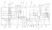
- a commercial vehicle is shown schematically, which is composed of a - powered - towing vehicle Z and a - pulled - vehicle trailer A, for example, a semi-trailer
- the electrical connection with respect to operating voltage and signal voltage between the trailer A and towing vehicle Z via flexible laid connection cable. 3 , 3.1, 3.2, 3.3.
- an electrical connection box 2 is attached near the front side wall 1 of the trailer vehicle A. This contains, facing the towing vehicle Z, the individual plug-in connections for the electrical connection to the towing vehicle.
- taillights are each summarized to taillight units L and usually perform the light functions of a brake light L1, a respective turn signal lamp L2, the tail light L3 and possibly a reversing light, a rear fog lamp or the license plate lights. In the drawing, only one of the two existing taillights L is shown.
- the individual taillights L1, L2, L3, etc. may be equipped with light-emitting diodes (LED) and corresponding ballast resistors for the light-emitting diodes instead of conventional light bulbs.
- LEDs are usually connected in the manner of a matrix consisting of parallel LED rows, which in turn consist of several LEDs.
- Each taillight unit L furthermore accommodates a BUS signal connection 11 and a light control unit 13 of a DC-BUS system supplying the taillight unit L with electrical voltage and with the ON and OFF signals for the individual light functions.
- a power supply 14 To supply the tail light side BUS signal connection 11 and control device 13 with the required operating voltage is a power supply 14. This is fed via the lines 7A, 8A of the electrical system of the vehicle.
- the electrical system is usually operated in commercial vehicles with 24 volts DC.
- the connection box 2 accommodates a central light control unit (ECU) 10 of the vehicle trailer provided with a processor (CPU) and, downstream of the signal, a BUS signal connection 6.
- the central light control unit 10 can be linked to various other control components of the vehicle electrical system via further signal lines, in particular with an arranged inside or outside the junction box, electronic brake control device for the brakes of the vehicle trailer.
- a power supply unit 9 To supply the bus signal connection 6 and the processor of the central light control unit 10 with sufficient operating voltage is a power supply unit 9.
- the power supply unit 9 is fed via the coming of the towing vehicle lines 7, 8.
- the trailer itself itself has no own operating voltage source.
- the signal output 22 of the central light control unit 10 is connected via the bus signal connection 6 and working as a bidirectional DC bus 7A line with positive potential and via the negative potential having ground conductor 8A with the light control components of the taillight unit L in combination.
- a ground potential 8A can also serve the vehicle chassis consisting of metal.
- the line strands 7A, 8A of the DC-BUS system work with the DC voltage of the electrical system, so here the DC voltage of the 24-volt electrical system 7, 8 of the towing vehicle, said voltage being modulated to transmit information BUS signals.
- the DC-BUS 7A is for modulating or reading the bus signals on the part of the central light control unit 10 with the bus signal connection 6, and connected on the side of each taillight unit L with the local, further bus signal connection 11.
- In the signal connections 6 and 11 are each transceiver, so they consist of a transmitting and a receiving module.
- the contacting of the guided along the trailer vehicle BUS line strands 7A, 8A to the signal connection 6 preferably via corresponding plug contacts 15 done.
- test program is integrated into the central light control unit 10, which performs a test routine R for checking all important functions of the light control unit immediately after each start of operation of the vehicle.
- the test routine R starts automatically with switching on the vehicle electrical system, i. when the light control unit 10 via the permanent plus input 21 detects the presence of the vehicle electrical system voltage of normally 24 volts in the line strands 7, 8.
- the execution of the test routine R takes a certain amount of time during which the regular signal processing in the light control unit 10 is interrupted. Although the interruption is less than a second, but during this period at the signal inputs 5.1 to 5.3 incoming brake or turn signals can not be processed temporarily to corresponding control signals of the DC-BUS system.
- legal regulations require that the delay between the signal-triggering event, e.g. the operation of the brake light transmitter in the towing vehicle Z, and the illumination of the brake light may not exceed 100 milliseconds.
- the light control unit 10 prevents the start of the test routine R when and if at one of the signal inputs 5.1, 5.2, 5.3, a switching signal is present without the concern of the vehicle electrical system voltage is detected at the signal input 21.
- the test routine R is started but not yet finished, it is aborted and restarted later.
- signals at 5.1, 5.2, 5.3 are therefore treated with priority over the start of the test routine.
- the junction box 2 may have, in addition to the plug contacts 15 of the lighting system via a connection for connection of the control unit of the electronic brake system of the vehicle trailer.
Abstract
Description
- Die Erfindung betrifft ein Verfahren zum Schalten einer Fahrzeugbeleuchtung, mit einer Lichtsteuereinheit mit Signaleingängen für auf dem Niveau der Fahrzeug-Versorgungsspannung liegende, fahrerseitige Schaltsignale und einem weiteren Eingang für die Fahrzeug-Versorgungsspannung, mit einem Signalausgang, welcher Teil einer bidirektionalen Daten-BUS-Verbindung zu den Fahrzeugleuchten ist, und mit einer vorzugsweise in die Lichtsteuereinheit implementierten Testroutine zur Überprüfung der Signalverarbeitung in der Lichtsteuereinheit, wobei die Spannung an dem weiteren Eingang überwacht wird und die Testroutine mit erstmaligem Anliegen einer allgemeinen Fahrzeug-Versorgungsspannung an dem weiteren Eingang startet.
- Auf dem Fahrzeugsektor werden zunehmend LED-Signalleuchten eingesetzt, da diese neben verbesserten lichttechnischen Eigenschaften eine höhere Standzeit im Vergleich zu konventionellen Glühbirnen haben. Die Ansteuerung von LED-Leuchten erfolgt häufig nicht konventionell, d. h. unmittelbar durch Schließen eines vom Fahrer kommenden Stromkreises, sondern indirekt über eine Lichtsteuereinheit. Das vom Fahrer kommende Schaltsignal gelangt zunächst, ebenso wie etwaige andere Schaltsignale, zu der Lichtsteuereinheit, in der in Abhängigkeit vom jeweiligen Schaltsignal ein Steuersignal für die betreffende Leuchteneinheit in Gang gesetzt wird. Häufig erfolgt diese weitere Signalübertragung über einen Daten-BUS in Form eines der Betriebsspannung des Fahrzeuges überlagerten Signals. Die Betriebsspannung beträgt bei Nutzfahrzeugen in der Regel 24 Volt.
- Für BUS-gesteuerte Beleuchtungssysteme, zu denen auch die Brems- und Blinkleuchten eines aus Zugfahrzeug und Anhängerfahrzeug bestehenden Fahrzeugverbandes zählen, besteht seitens des Gesetzgebers die Forderung, dass diese innerhalb einer vorgegebenen Schwellzeit ihre Soll-Lichtstärke erreichen. Elektronische Lichtsteuerungen unter Einsatz eines BUS-Systems verursachen jedoch Totzeiten für den Kommunikationsaufbau. Besteht keine permanente Stromversorgung, ist auch für die Initialisierung der Elektronik eine gewisse Zeitspanne erforderlich.
- Zur Vermeidung solcher Verzögerungen arbeiten BUS-gesteuerte Fahrzeugbeleuchtungsanlagen für einen ordnungsgemäßen Betrieb mit einer permanenten Stromversorgung der signalverarbeitenden Einheiten, und insbesondere der elektronischen Lichtsteuereinheit.
- Der Erfindung liegt die Aufgabe zugrunde, den ordnungsgemäßen Betrieb einer BUS-gesteuerten Beleuchtungsanlage eines Kraftfahrzeuges und vorzugsweise eines Verbandes aus Zug- und Anhängerfahrzeug sicherzustellen, ohne eine permanente Versorgung der signaltechnischen Einheiten und insbesondere der Lichtsteuereinheit mit der Fahrzeug-Betriebsspannung zu benötigen.
- Zur Lösung dieser Aufgabe wird bei einem Verfahren mit den eingangs angegebenen Merkmalen vorgeschlagen, dass das Starten der Testroutine dann unterbleibt, wenn an einem der Signaleingänge ein fahrerseitiges Schaltsignal vorliegt. Alternativ wird bei noch nicht beendeter Testroutine diese abgebrochen, sobald an einem der Signaleingänge ein fahrerseitiges Schaltsignal vorliegt.
- Im Falle einer noch nicht oder nicht vollständig aufgebauten Dauerstromversorgung und bei gleichzeitigem Vorliegen eines fahrerseitigen Schaltsignals an der Lichtsteuereinheit wird die eigentlich anstehende Testroutine temporär übersprungen oder jedenfalls zeitlich zunächst zurückgestellt, und so die verzögerungsfreie Ausführung des vom Fahrer geschalteten Lichtsignals mit Priorität behandelt. Alternativ wird, sofern die Testroutine bereits begonnen hat und noch nicht abgeschlossen ist, diese abgebrochen oder unterbrochen, sobald an einem der Signaleingänge der Lichtsteuereinheit ein fahrerseitiges Schaltsignal vorliegt. Wiederum wird dieses Schaltsignal mit Priorität behandelt und so der Lichtbefehl sofort und ohne zeitliche Verzögerung ausgeführt.
- Das zu der Lichtsteuereinheit gelangende, auf dem Niveau der Fahrzeug-Versorgungsspannung bzw. Betriebsspannung liegende Schaltsignal wird, sofern die permanente Fahrzeug-Versorgungsspannung (Dauerplus-Versorgung) noch nicht oder nicht vollständig aufgebaut ist, als Versorgungsspannung für die Lichtsteuereinheit verwendet, und dient zusätzlich der Energieversorgung auch des BUS-Systems. Die Signalspannung des durch den Fahrer geschalteten Stromkreises (z. B. der Schaltkreis für das Bremslicht) dient daher bei Fehlen der allgemeinen Fahrzeug-Versorgungsspannung (Dauerplus-Versorgung) zeitgleich als Energielieferant für sowohl elektronische Steuerkomponenten, als auch für den Betrieb des jeweiligen Leuchtmittels, z. B. einer LED-Leuchteneinheit.
- Das Verfahren eignet sich daher universell zum Einsatz in Fahrzeugen mit, als auch in Fahrzeugen ohne Dauerplus-Versorgung, und erfüllt die gesetzlichen Anforderungen an die Bereitschaft der wichtigsten Fahrzeugleuchten mit einem Zeitraum zwischen Signalauslösung seitens des Fahrers und dem Erreichen der Soll-Lichtstärke von unter 100 Millisekunden.
- Weitere Vorteile und Einzelheiten ergeben sich auch aus der nachfolgenden Beschreibung, in der auf die zugehörige Zeichnung Bezug genommen wird. Diese zeigt in stark schematischer Darstellung das fahrzeugelektrische Layout eines aus einem Zugfahrzeug und einem Anhängerfahrzeug bestehenden Fahrzeugverbandes.
- Auf der Zeichnung ist schematisch ein Nutzfahrzeug wiedergegeben, welches sich aus einem - angetriebenen - Zugfahrzeug Z und einem - gezogenen - Fahrzeuganhänger A, zum Beispiel einem Sattelauflieger zusammensetzt Die elektrische Verbindung hinsichtlich Betriebsspannung und Signalspannung zwischen Anhängerfahrzeug A und Zugfahrzeug Z erfolgt über flexibel verlegte Anschlusskabel 3, 3.1, 3.2, 3.3. Nahe der vorderen Bordwand 1 des Anhängerfahrzeuges A ist eine elektrische Anschlussbox 2 befestigt. Diese enthält, dem Zugfahrzeug Z zugewandt, die einzelnen Steckanschlüsse für die elektrische Verbindung mit dem Zugfahrzeug.
- Am anderen, d. h. rückwärtigen Ende des Fahrzeuganhängers A befindet sich in üblicher Weise eine linke und eine rechte Rückleuchte des Beleuchtungssystems des Anhängerfahrzeugs. Die Rückleuchten sind jeweils zu Rückleuchteneinheiten L zusammengefasst und führen üblicherweise die Lichtfunktionen einer Bremsleuchte L1, einer jeweiligen Blinkerleuchte L2, des Rücklichts L3 und ggf. eines Rückfahrlichts, einer Nebelschlussleuchte oder der Kennzeichenbeleuchtung aus. Auf der Zeichnung ist nur eine der zwei vorhandenen Rückleuchteneinheiten L dargestellt.
- Die einzelnen Rückleuchten L1, L2, L3 etc. können statt mit herkömmlichen Glühbirnen mit Leuchtdioden (LED) und entsprechenden Vorschaltwiderständen für die Leuchtdioden bestückt sein. Die Leuchtdioden sind üblicherweise nach Art einer Matrix geschaltet, bestehend aus parallelen LED-Reihen, die ihrerseits aus mehreren LED bestehen.
- Jede Rückleuchteneinheit L nimmt ferner eine BUS-Signalanbindung 11 sowie eine Lichtsteuereinheit 13 eines die Rückleuchteneinheit L mit elektrischer Spannung sowie mit den Ein- und Ausschaltsignalen für die einzelnen Lichtfunktionen versorgenden DC-BUS-Systems auf. Zur Versorgung der rückleuchtenseitigen BUS-Signalanbindung 11 und Steuereinrichtung 13 mit der erforderlichen Betriebsspannung dient ein Netzteil 14. Dieses wird über die Leitungen 7A, 8A des Bordnetzes des Fahrzeugs gespeist. Das Bordnetz wird bei Nutzfahrzeugen üblicherweise mit 24 Volt Gleichspannung betrieben.
- Die Anschlussbox 2 nimmt eine mit einem Prozessor (CPU) versehene zentrale Lichtsteuereinheit (ECU) 10 des Fahrzeuganhängers auf sowie, signaltechnisch nachgeschaltet, eine BUS-Signalanbindung 6. Die zentrale Lichtsteuereinheit 10 kann über weitere Signalleitungen mit verschiedenen anderen Steuerkomponenten der Fahrzeugelektrik verknüpft sein, insbesondere mit einem innerhalb oder auch außerhalb der Anschlussbox angeordneten, elektronischen Bremsensteuergerät für die Bremsen des Fahrzeuganhängers. Zur Versorgung der BUS-Signalanbindung 6 und des Prozessors der zentralen Lichtsteuereinheit 10 mit ausreichender Betriebsspannung dient ein Netzteil 9. Das Netzteil 9 wird über die vom Zugfahrzeug kommenden Leitungen 7, 8 gespeist. Der Anhänger selbst verfügt über keine eigene Betriebsspannungsquelle.
- Der Signalausgang 22 der zentralen Lichtsteuereinheit 10 steht über die BUS-Signalanbindung 6 und eine als bidirektionaler DC-BUS 7A arbeitende Leitung mit positivem Potential sowie über den das negative Potential aufweisenden Masseleiter 8A mit den Lichtsteuerkomponenten der Rückleuchteneinheit L in Verbindung. Als Massepotential 8, 8A kann auch das aus Metall bestehende Fahrzeugchassis dienen.
- Die Leitungsstränge 7A, 8A des DC-BUS-Systems arbeiten mit der Gleichspannung des Bordnetzes, hier also der Gleichspannung des 24-Volt-Bordnetzes 7, 8 des Zugfahrzeuges, wobei dieser Spannung zur Übertragung von Informationen BUS-Signale aufmoduliert sind. Der DC-BUS 7A ist zum Aufmodulieren bzw. Auslesen der BUS-Signale auf Seiten der zentralen Lichtsteuereinheit 10 mit der BUS-Signalanbindung 6, und auf Seiten jeder Rückleuchteneinheit L mit der dortigen, weiteren BUS-Signalanbindung 11 verbunden. Bei den Signalanbindungen 6 und 11 handelt es sich jeweils um Transceiver, sie bestehen also aus einem Sende- und einem Empfangsmodul. An der Anschlussbox 2 erfolgen die Kontaktierungen der längs des Anhängerfahrzeuges geführten BUS-Leitungsstränge 7A, 8A an die Signalanbindung 6 vorzugsweise über entsprechende Steckkontakte 15.
- Wird im Zugfahrzeug Z seitens des Fahrers z. B. der Blinkerschalter "rechts" betätigt, so schließt sich ein entsprechender, über das Anschlusskabel 3.2 zum Anhängerfahrzeug geführter Stromkreis. Dies führt zu einem entsprechenden Signaleingang 5.2 an der zentralen Lichtsteuereinheit 10, was durch diese detektiert wird. Die Lichtsteuereinheit 10 initiiert daraufhin über die BUS-Signalanbindung 6 ein der Gleichspannung in der Dauerplus-Leitung 7 aufmoduliertes BUS-Signal zum Einschalten der Blinklichter L2 der rechten Rückleuchte. In der in der rechten Rückleuchteneinheit L angeordneten BUS-Signalanbindung 11 erfolgt die Trennung des in dem Leitungsstrang 7A überlagerten BUS-Signals. An die BUS-Signalanbindung 11 ist, ebenfalls innerhalb der Rückleuchteneinheit L, die rückleuchtenseitige Steuereinrichtung 13 angeschlossen, deren Ausgangssignale Schaltsignale S1, S2, S3 etc. zur Betätigung von Schaltelementen 12 der einzelnen Lichtfunktionen L1, L2, L3 sind. Im hier beschriebenen Beispiel kommt es also am Signalausgang der Steuereinrichtung 13 zu einem Schaltsignal S2 und damit zu einem Ein- bzw. Ausschalten der jeweiligen LEDs des rechten Blinklichts L2.
- Programmtechnisch ist in die zentrale Lichtsteuereinheit 10 ein Testprogramm integriert, welches unmittelbar nach jedem Betriebsstart des Fahrzeugs zunächst eine Testroutine R zur Überprüfung aller wichtigen Funktionen der Lichtsteuereinheit durchführt. Die Testroutine R startet selbsttätig mit Einschalten des Bordnetzes, d.h. sobald die Lichtsteuereinheit 10 über den Dauerplus-Eingang 21 das Vorhandensein der Bordnetzspannung von normalerweise 24 Volt in den Leitungssträngen 7, 8 feststellt.
- Die Durchführung der Testroutine R nimmt eine gewisse Zeitdauer in Anspruch, während der die reguläre Signalverarbeitung in der Lichtsteuereinheit 10 unterbrochen ist. Die Unterbrechung beträgt zwar weniger als eine Sekunde, jedoch können in diesem Zeitraum an den Signaleingängen 5.1 bis 5.3 eintreffende Brems- oder Blinkersignale vorübergehend nicht zu entsprechenden Steuersignalen des DC-BUS-Systems verarbeitet werden. Andererseits verlangen gesetzliche Bestimmungen, dass die Verzögerung zwischen dem signalauslösenden Ereignis, also z.B. der Betätigung des Bremslichtgebers im Zugfahrzeug Z, und dem Aufleuchten des Bremslichts nicht mehr als 100 Millisekunden betragen darf.
- Aus diesem Grunde verhindert die Lichtsteuereinheit 10 das Starten der Testroutine R, wenn und soweit an einem der Signaleingänge 5.1, 5.2, 5.3 ein Schaltsignal vorliegt, ohne dass an dem Signaleingang 21 das Anliegen der Bordnetzspannung feststellbar ist. Alternativ wird, wenn in diesem Fall die Testroutine R zwar gestartet aber noch nicht beendet ist, diese abgebrochen und später neu gestartet. Innerhalb der Lichtsteuereinheit 10 werden daher Signale bei 5.1, 5.2, 5.3 mit Priorität gegenüber dem Starten der Testroutine behandelt. Durch die Testroutine R und für deren Dauer kommt es zu keinen Verzögerungen in der regulären Signalverarbeitung.
- Die Anschlussbox 2 kann neben den Steckkontakten 15 des Beleuchtungssystems über eine Verbindung zum Anschluss der Steuereinheit des elektronischen Bremssystems des Fahrzeuganhängers verfügen.
- Damit wird die Voraussetzung für eine signaltechnische Verknüpfung der Steuereinheit des elektronischen Bremssystems mit der Lichtsteuereinheit 10 geschaffen. Durch die signaltechnische Verknüpfung der Steuereinheit des elektrischen Bremssystems mit der Lichtsteuereinheit lässt sich ein "intelligentes" Beleuchtungssystem mit vorteilhaften Funktionen wie z.B. Rückfahrsystemen, einem adaptiven (von der Stärke des Bremsvorgangs abhängigen) Bremslicht und dergleichen weitere Funktionen schaffen.
-
- 1
- Bordwand
- 2
- Anschlussbox
- 3
- Anschluss zum Zugfahrzeug
- 3.1
- Anschluss zum Zugfahrzeug
- 3.2
- Anschluss zum Zugfahrzeug
- 3.3
- Anschluss zum Zugfahrzeug
- 5.1
- Signaleingang
- 5.2
- Signaleingang
- 5.3
- Signaleingang
- 6
- Transceiver, BUS-Signalanbindung
- 7
- Plusleiter Bordnetz
- 7A
- Daten-BUS
- 8
- Masseleiter
- 8A
- Masseleiter
- 9
- Netzteil
- 10
- Lichtsteuereinheit (ECU)
- 11
- Transceiver, BUS-Signalanbindung
- 12
- Schaltelement
- 13
- Steuereinrichtung
- 14
- Netzteil
- 15
- Steckkontakt
- 21
- Signaleingang Bordnetzspannung
- 22
- Signalausgang
- A
- Anhängerfahrzeug
- L
- Rückleuchteneinheit
- L1
- Lichtfunktion
- L2
- Lichtfunktion
- L3
- Lichtfunktion
- R
- Testroutine
- S1
- Schaltsignal
- S2
- Schaltsignal
- S3
- Schaltsignal
- Z
- Zugfahrzeug
Claims (3)
- Verfahren zum Schalten einer Fahrzeugbeleuchtung, mit einer Lichtsteuereinheit (10) mit Signaleingängen (5.1, 5.2, 5.3) für auf dem Niveau der Fahrzeug-Versorgungsspannung liegende, fahrerseitige Schaltsignale und einem weiteren Eingang (21) für die Fahrzeug-Versorgungsspannung, mit einem Signalausgang, welcher Teil einer bidirektionalen Daten-BUS-Verbindung (7A, 8A) zu den Fahrzeugleuchten (L1, L2, L3) ist, und mit einer vorzugsweise in die Lichtsteuereinheit (10) implementierten Testroutine (R) zur Überprüfung der Signalverarbeitung in der Lichtsteuereinheit (10), wobei die Spannung an dem weiteren Eingang (21) überwacht wird und die Testroutine (R) mit erstmaligem Anliegen einer allgemeinen Fahrzeug-Versorgungsspannung an dem weiteren Eingang (21) startet,
dadurch gekennzeichnet,
dass das Starten der Testroutine (R) dann unterbleibt, wenn an einem der Signaleingänge (5.1, 5.2, 5.3) ein fahrerseitiges Schaltsignal vorliegt. - Verfahren zum Schalten einer Fahrzeugbeleuchtung, mit einer Lichtsteuereinheit (10) mit Signaleingängen (5.1, 5.2, 5.3) für auf dem Niveau der Fahrzeug-Versorgungsspannung liegende, fahrerseitige Schaltsignale und einem weiteren Eingang (21) für die Fahrzeug-Versorgungsspannung, mit einem Signalausgang, welcher Teil einer bidirektionalen Daten-BUS-Verbindung (7A, 8A) zu den Fahrzeugleuchten (L1, L2, L3) ist, und mit einer vorzugsweise in die Lichtsteuereinheit (10) implementierten Testroutine (R) zur Überprüfung der Signalverarbeitung in der Lichtsteuereinheit (10), wobei die Spannung an dem weiteren Eingang (21) überwacht wird und die Testroutine (R) mit erstmaligem Anliegen einer allgemeinen Fahrzeug-Versorgungsspannung an dem weiteren Eingang (21) startet,
dadurch gekennzeichnet,
dass bei noch nicht beendeter Testroutine (R) diese abgebrochen wird, sobald an einem der Signaleingänge ein fahrerseitiges Schaltsignal vorliegt. - Verfahren zum Schalten einer Fahrzeugbeleuchtung nach Anspruch 1 oder Anspruch 2, dadurch gekennzeichnet, dass die Testroutine (R) nach Beenden des fahrerseitigen Schaltsignals gestartet bzw. neu gestartet wird.
Applications Claiming Priority (1)
| Application Number | Priority Date | Filing Date | Title |
|---|---|---|---|
| DE102010016804A DE102010016804A1 (de) | 2010-05-05 | 2010-05-05 | Verfahren zum Schalten einer Fahrzeugbeleuchtung |
Publications (2)
| Publication Number | Publication Date |
|---|---|
| EP2384935A1 true EP2384935A1 (de) | 2011-11-09 |
| EP2384935B1 EP2384935B1 (de) | 2016-08-24 |
Family
ID=44278984
Family Applications (1)
| Application Number | Title | Priority Date | Filing Date |
|---|---|---|---|
| EP11161656.1A Not-in-force EP2384935B1 (de) | 2010-05-05 | 2011-04-08 | Verfahren zum Schalten einer Fahrzeugbeleuchtung |
Country Status (2)
| Country | Link |
|---|---|
| EP (1) | EP2384935B1 (de) |
| DE (1) | DE102010016804A1 (de) |
Cited By (1)
| Publication number | Priority date | Publication date | Assignee | Title |
|---|---|---|---|---|
| EP2628642A3 (de) * | 2012-02-16 | 2013-09-18 | Alois Pöttinger Maschinenfabrik Ges. m.b.H. | Landwirtschaftliches Anbaugerät zum Koppeln mit einem Arbeitsfahrzeug |
Citations (6)
| Publication number | Priority date | Publication date | Assignee | Title |
|---|---|---|---|---|
| EP0430792A1 (de) * | 1989-11-27 | 1991-06-05 | Valeo Vision | Verbesserung fÀ¼r Multiplex-Steuergeräte für eine Anordnung elektrischer Elemente in einem Kraftfahrzeug |
| EP0504549A2 (de) * | 1991-03-08 | 1992-09-23 | Sumitomo Wiring Systems, Ltd. | Multiplex-Kommunikationseinheit |
| EP0773139A2 (de) * | 1995-11-09 | 1997-05-14 | ERICH JAEGER GmbH & Co. KG | Steuer- und Überwachungsvorrichtung für Anhängerfunktionen |
| DE10127056A1 (de) * | 2001-06-02 | 2002-12-05 | Bosch Gmbh Robert | Vorrichtung zur sicheren Signalerzeugung |
| DE10236301A1 (de) * | 2002-08-08 | 2004-02-19 | Hella Kg Hueck & Co. | Schaltungsanordnung zur schnellen Ansteuerung und Überwachung elektrischer Beleuchtungseinrichtungen in Anhängerfahrzeugen |
| DE202005017151U1 (de) * | 2005-03-15 | 2005-12-29 | Conwys Ag | Steuerungsvorrichtung für Anhänger und Fahrradträger |
Family Cites Families (6)
| Publication number | Priority date | Publication date | Assignee | Title |
|---|---|---|---|---|
| DE3526562A1 (de) * | 1985-07-25 | 1987-02-05 | Ulrich Kamin | Einrichtung zum rberwachen der elektrischen stromkreise von kraftfahrzeugen |
| JPH05170045A (ja) * | 1991-12-24 | 1993-07-09 | Mitsubishi Electric Corp | 車両用乗員保護装置の起動装置 |
| DE4418072C1 (de) * | 1994-05-24 | 1995-03-30 | Daimler Benz Ag | Verfahren zur Auswertung der Eigendiagnose eines Steuergerätes im Kraftfahrzeug |
| DE19821784B4 (de) * | 1997-05-15 | 2004-04-22 | Toyota Jidosha K.K., Toyota | Vorrichtung zum Aktivieren einer passiven Sicherheitsvorrichtung |
| DE19852351A1 (de) * | 1998-11-13 | 2000-05-18 | Hella Kg Hueck & Co | Diagnosesystem für eine LED-Leuchte in einem Kraftfahrzeug |
| US7076347B2 (en) * | 2004-01-23 | 2006-07-11 | General Motors Corporation | Brake booster vacuum sensor diagnostic |
-
2010
- 2010-05-05 DE DE102010016804A patent/DE102010016804A1/de not_active Withdrawn
-
2011
- 2011-04-08 EP EP11161656.1A patent/EP2384935B1/de not_active Not-in-force
Patent Citations (6)
| Publication number | Priority date | Publication date | Assignee | Title |
|---|---|---|---|---|
| EP0430792A1 (de) * | 1989-11-27 | 1991-06-05 | Valeo Vision | Verbesserung fÀ¼r Multiplex-Steuergeräte für eine Anordnung elektrischer Elemente in einem Kraftfahrzeug |
| EP0504549A2 (de) * | 1991-03-08 | 1992-09-23 | Sumitomo Wiring Systems, Ltd. | Multiplex-Kommunikationseinheit |
| EP0773139A2 (de) * | 1995-11-09 | 1997-05-14 | ERICH JAEGER GmbH & Co. KG | Steuer- und Überwachungsvorrichtung für Anhängerfunktionen |
| DE10127056A1 (de) * | 2001-06-02 | 2002-12-05 | Bosch Gmbh Robert | Vorrichtung zur sicheren Signalerzeugung |
| DE10236301A1 (de) * | 2002-08-08 | 2004-02-19 | Hella Kg Hueck & Co. | Schaltungsanordnung zur schnellen Ansteuerung und Überwachung elektrischer Beleuchtungseinrichtungen in Anhängerfahrzeugen |
| DE202005017151U1 (de) * | 2005-03-15 | 2005-12-29 | Conwys Ag | Steuerungsvorrichtung für Anhänger und Fahrradträger |
Cited By (1)
| Publication number | Priority date | Publication date | Assignee | Title |
|---|---|---|---|---|
| EP2628642A3 (de) * | 2012-02-16 | 2013-09-18 | Alois Pöttinger Maschinenfabrik Ges. m.b.H. | Landwirtschaftliches Anbaugerät zum Koppeln mit einem Arbeitsfahrzeug |
Also Published As
| Publication number | Publication date |
|---|---|
| EP2384935B1 (de) | 2016-08-24 |
| DE102010016804A1 (de) | 2011-11-10 |
Similar Documents
| Publication | Publication Date | Title |
|---|---|---|
| EP1702802B1 (de) | Steuerungsvorrichtung für Anhänger und Fahrradträger | |
| DE102013212793A1 (de) | Fahrzeugbremsleuchtensystem und Verfahren, um ein folgendes Fahrzeug auf einen unsicheren Folgeabstand hinzuweisen | |
| DE102011082996A1 (de) | Bremsleuchten-Ansteuervorrichtung | |
| DE102010015754B4 (de) | Verfahren und Systeme zum Steuern einer Vorwärtsbeleuchtung für Fahrzeuge | |
| WO2006053651A1 (de) | Nutzfahrzeug mit über plc steuerbaren beleuchtungseinheiten | |
| DE10243792A1 (de) | Inspektionssystem für eine Fahrzeugleuchte | |
| WO2010054707A1 (de) | Nummerschildhalter | |
| EP0692396A1 (de) | Elektrisches Anhängeranschlussgerät für ein Zugfahrzeug | |
| DE102015214337B3 (de) | Verfahren und Vorrichtung zur Bestimmung einer Deichsellänge eines Anhängers in einem Fahrzeug-Anhänger-Gespann | |
| DE102009052590A1 (de) | Vorrichtung und Verfahren zur Überwachung und Signalisierung von Verkehrssituationen und Betriebszuständen in einem Fahrzeug und im Umfeld des Fahrzeugs | |
| WO2015055273A1 (de) | Fahrzeug und verfahren zum ausleuchten eines bereichs hinter einem fahrzeug | |
| EP2287043B1 (de) | Fahrzeugbeleuchtungssystem mit Detektierung und Anzeige eines Ausfalls einer LED-Fahrzeugleuchte | |
| EP2384935B1 (de) | Verfahren zum Schalten einer Fahrzeugbeleuchtung | |
| DE102019130688A1 (de) | Verfahren zum Konfigurieren eines Anhängerdetektionssystems | |
| DE102008054349A1 (de) | Steuerungsanordnung für ein Anhängefahrzeug, Anhängefahrzeug und Adapter | |
| DE102009044055A1 (de) | Elektrische Anschlusseinheit für ein Anhängerfahrzeug | |
| DE102017008185A1 (de) | Verfahren zur Unterstützung des Fahrers eines Fahrzeugs und elektronisches Bremssystem | |
| DE102011050407B4 (de) | Fahrzeugheckleuchte mit akustischem Rückfahrwarner | |
| DE102009044056A1 (de) | Fahrzeugbeleuchtungssystem mit einer Lichtsteuereinheit | |
| EP2364259A1 (de) | Abstandssensorvorrichtung für ein anhängefahrzeug und anhängefahrzeug | |
| DE102012222013B4 (de) | Kombinierte Steuervorrichtung und Verfahren für eine Leuchte eines Fahrzeugs | |
| DE202007017871U1 (de) | Automatische Abschaltung des Bremslichtes | |
| DE102016006637B4 (de) | Fahrtrichtungsanzeiger-Steuermodul | |
| DE10063802C2 (de) | Einrichtung zum Erkennen eines an einem Zugfahrzeug angekuppelten Anhängers | |
| DE202010016339U1 (de) | Schaltungsanordnung |
Legal Events
| Date | Code | Title | Description |
|---|---|---|---|
| AK | Designated contracting states |
Kind code of ref document: A1 Designated state(s): AL AT BE BG CH CY CZ DE DK EE ES FI FR GB GR HR HU IE IS IT LI LT LU LV MC MK MT NL NO PL PT RO RS SE SI SK SM TR |
|
| AX | Request for extension of the european patent |
Extension state: BA ME |
|
| PUAI | Public reference made under article 153(3) epc to a published international application that has entered the european phase |
Free format text: ORIGINAL CODE: 0009012 |
|
| 17P | Request for examination filed |
Effective date: 20120507 |
|
| GRAP | Despatch of communication of intention to grant a patent |
Free format text: ORIGINAL CODE: EPIDOSNIGR1 |
|
| RIC1 | Information provided on ipc code assigned before grant |
Ipc: B60Q 11/00 20060101ALI20160223BHEP Ipc: B60R 16/03 20060101ALN20160223BHEP Ipc: B60Q 1/30 20060101AFI20160223BHEP Ipc: H05B 33/08 20060101ALI20160223BHEP |
|
| INTG | Intention to grant announced |
Effective date: 20160322 |
|
| GRAS | Grant fee paid |
Free format text: ORIGINAL CODE: EPIDOSNIGR3 |
|
| GRAA | (expected) grant |
Free format text: ORIGINAL CODE: 0009210 |
|
| AK | Designated contracting states |
Kind code of ref document: B1 Designated state(s): AL AT BE BG CH CY CZ DE DK EE ES FI FR GB GR HR HU IE IS IT LI LT LU LV MC MK MT NL NO PL PT RO RS SE SI SK SM TR |
|
| REG | Reference to a national code |
Ref country code: GB Ref legal event code: FG4D Free format text: NOT ENGLISH |
|
| REG | Reference to a national code |
Ref country code: CH Ref legal event code: EP |
|
| REG | Reference to a national code |
Ref country code: AT Ref legal event code: REF Ref document number: 822735 Country of ref document: AT Kind code of ref document: T Effective date: 20160915 |
|
| REG | Reference to a national code |
Ref country code: IE Ref legal event code: FG4D Free format text: LANGUAGE OF EP DOCUMENT: GERMAN |
|
| REG | Reference to a national code |
Ref country code: DE Ref legal event code: R096 Ref document number: 502011010483 Country of ref document: DE |
|
| REG | Reference to a national code |
Ref country code: SE Ref legal event code: TRGR |
|
| REG | Reference to a national code |
Ref country code: LT Ref legal event code: MG4D |
|
| REG | Reference to a national code |
Ref country code: NL Ref legal event code: MP Effective date: 20160824 |
|
| PG25 | Lapsed in a contracting state [announced via postgrant information from national office to epo] |
Ref country code: LT Free format text: LAPSE BECAUSE OF FAILURE TO SUBMIT A TRANSLATION OF THE DESCRIPTION OR TO PAY THE FEE WITHIN THE PRESCRIBED TIME-LIMIT Effective date: 20160824 Ref country code: IT Free format text: LAPSE BECAUSE OF FAILURE TO SUBMIT A TRANSLATION OF THE DESCRIPTION OR TO PAY THE FEE WITHIN THE PRESCRIBED TIME-LIMIT Effective date: 20160824 Ref country code: NO Free format text: LAPSE BECAUSE OF FAILURE TO SUBMIT A TRANSLATION OF THE DESCRIPTION OR TO PAY THE FEE WITHIN THE PRESCRIBED TIME-LIMIT Effective date: 20161124 Ref country code: NL Free format text: LAPSE BECAUSE OF FAILURE TO SUBMIT A TRANSLATION OF THE DESCRIPTION OR TO PAY THE FEE WITHIN THE PRESCRIBED TIME-LIMIT Effective date: 20160824 Ref country code: HR Free format text: LAPSE BECAUSE OF FAILURE TO SUBMIT A TRANSLATION OF THE DESCRIPTION OR TO PAY THE FEE WITHIN THE PRESCRIBED TIME-LIMIT Effective date: 20160824 Ref country code: RS Free format text: LAPSE BECAUSE OF FAILURE TO SUBMIT A TRANSLATION OF THE DESCRIPTION OR TO PAY THE FEE WITHIN THE PRESCRIBED TIME-LIMIT Effective date: 20160824 Ref country code: FI Free format text: LAPSE BECAUSE OF FAILURE TO SUBMIT A TRANSLATION OF THE DESCRIPTION OR TO PAY THE FEE WITHIN THE PRESCRIBED TIME-LIMIT Effective date: 20160824 |
|
| PG25 | Lapsed in a contracting state [announced via postgrant information from national office to epo] |
Ref country code: GR Free format text: LAPSE BECAUSE OF FAILURE TO SUBMIT A TRANSLATION OF THE DESCRIPTION OR TO PAY THE FEE WITHIN THE PRESCRIBED TIME-LIMIT Effective date: 20161125 Ref country code: LV Free format text: LAPSE BECAUSE OF FAILURE TO SUBMIT A TRANSLATION OF THE DESCRIPTION OR TO PAY THE FEE WITHIN THE PRESCRIBED TIME-LIMIT Effective date: 20160824 Ref country code: ES Free format text: LAPSE BECAUSE OF FAILURE TO SUBMIT A TRANSLATION OF THE DESCRIPTION OR TO PAY THE FEE WITHIN THE PRESCRIBED TIME-LIMIT Effective date: 20160824 Ref country code: PT Free format text: LAPSE BECAUSE OF FAILURE TO SUBMIT A TRANSLATION OF THE DESCRIPTION OR TO PAY THE FEE WITHIN THE PRESCRIBED TIME-LIMIT Effective date: 20161226 |
|
| PG25 | Lapsed in a contracting state [announced via postgrant information from national office to epo] |
Ref country code: EE Free format text: LAPSE BECAUSE OF FAILURE TO SUBMIT A TRANSLATION OF THE DESCRIPTION OR TO PAY THE FEE WITHIN THE PRESCRIBED TIME-LIMIT Effective date: 20160824 Ref country code: RO Free format text: LAPSE BECAUSE OF FAILURE TO SUBMIT A TRANSLATION OF THE DESCRIPTION OR TO PAY THE FEE WITHIN THE PRESCRIBED TIME-LIMIT Effective date: 20160824 |
|
| REG | Reference to a national code |
Ref country code: DE Ref legal event code: R097 Ref document number: 502011010483 Country of ref document: DE |
|
| PG25 | Lapsed in a contracting state [announced via postgrant information from national office to epo] |
Ref country code: PL Free format text: LAPSE BECAUSE OF FAILURE TO SUBMIT A TRANSLATION OF THE DESCRIPTION OR TO PAY THE FEE WITHIN THE PRESCRIBED TIME-LIMIT Effective date: 20160824 Ref country code: CZ Free format text: LAPSE BECAUSE OF FAILURE TO SUBMIT A TRANSLATION OF THE DESCRIPTION OR TO PAY THE FEE WITHIN THE PRESCRIBED TIME-LIMIT Effective date: 20160824 Ref country code: SK Free format text: LAPSE BECAUSE OF FAILURE TO SUBMIT A TRANSLATION OF THE DESCRIPTION OR TO PAY THE FEE WITHIN THE PRESCRIBED TIME-LIMIT Effective date: 20160824 Ref country code: DK Free format text: LAPSE BECAUSE OF FAILURE TO SUBMIT A TRANSLATION OF THE DESCRIPTION OR TO PAY THE FEE WITHIN THE PRESCRIBED TIME-LIMIT Effective date: 20160824 Ref country code: BG Free format text: LAPSE BECAUSE OF FAILURE TO SUBMIT A TRANSLATION OF THE DESCRIPTION OR TO PAY THE FEE WITHIN THE PRESCRIBED TIME-LIMIT Effective date: 20161124 Ref country code: SM Free format text: LAPSE BECAUSE OF FAILURE TO SUBMIT A TRANSLATION OF THE DESCRIPTION OR TO PAY THE FEE WITHIN THE PRESCRIBED TIME-LIMIT Effective date: 20160824 |
|
| PLBE | No opposition filed within time limit |
Free format text: ORIGINAL CODE: 0009261 |
|
| STAA | Information on the status of an ep patent application or granted ep patent |
Free format text: STATUS: NO OPPOSITION FILED WITHIN TIME LIMIT |
|
| 26N | No opposition filed |
Effective date: 20170526 |
|
| PG25 | Lapsed in a contracting state [announced via postgrant information from national office to epo] |
Ref country code: SI Free format text: LAPSE BECAUSE OF FAILURE TO SUBMIT A TRANSLATION OF THE DESCRIPTION OR TO PAY THE FEE WITHIN THE PRESCRIBED TIME-LIMIT Effective date: 20160824 |
|
| REG | Reference to a national code |
Ref country code: CH Ref legal event code: PL |
|
| REG | Reference to a national code |
Ref country code: IE Ref legal event code: MM4A |
|
| REG | Reference to a national code |
Ref country code: FR Ref legal event code: ST Effective date: 20171229 |
|
| PG25 | Lapsed in a contracting state [announced via postgrant information from national office to epo] |
Ref country code: FR Free format text: LAPSE BECAUSE OF NON-PAYMENT OF DUE FEES Effective date: 20170502 Ref country code: MC Free format text: LAPSE BECAUSE OF FAILURE TO SUBMIT A TRANSLATION OF THE DESCRIPTION OR TO PAY THE FEE WITHIN THE PRESCRIBED TIME-LIMIT Effective date: 20160824 |
|
| PG25 | Lapsed in a contracting state [announced via postgrant information from national office to epo] |
Ref country code: LI Free format text: LAPSE BECAUSE OF NON-PAYMENT OF DUE FEES Effective date: 20170430 Ref country code: CH Free format text: LAPSE BECAUSE OF NON-PAYMENT OF DUE FEES Effective date: 20170430 Ref country code: LU Free format text: LAPSE BECAUSE OF NON-PAYMENT OF DUE FEES Effective date: 20170408 |
|
| REG | Reference to a national code |
Ref country code: BE Ref legal event code: MM Effective date: 20170430 |
|
| PG25 | Lapsed in a contracting state [announced via postgrant information from national office to epo] |
Ref country code: IE Free format text: LAPSE BECAUSE OF NON-PAYMENT OF DUE FEES Effective date: 20170408 |
|
| PG25 | Lapsed in a contracting state [announced via postgrant information from national office to epo] |
Ref country code: BE Free format text: LAPSE BECAUSE OF NON-PAYMENT OF DUE FEES Effective date: 20170430 |
|
| REG | Reference to a national code |
Ref country code: AT Ref legal event code: MM01 Ref document number: 822735 Country of ref document: AT Kind code of ref document: T Effective date: 20170408 |
|
| PGFP | Annual fee paid to national office [announced via postgrant information from national office to epo] |
Ref country code: DE Payment date: 20180515 Year of fee payment: 8 |
|
| PG25 | Lapsed in a contracting state [announced via postgrant information from national office to epo] |
Ref country code: AT Free format text: LAPSE BECAUSE OF NON-PAYMENT OF DUE FEES Effective date: 20170408 |
|
| PG25 | Lapsed in a contracting state [announced via postgrant information from national office to epo] |
Ref country code: MT Free format text: LAPSE BECAUSE OF FAILURE TO SUBMIT A TRANSLATION OF THE DESCRIPTION OR TO PAY THE FEE WITHIN THE PRESCRIBED TIME-LIMIT Effective date: 20160824 |
|
| PGFP | Annual fee paid to national office [announced via postgrant information from national office to epo] |
Ref country code: SE Payment date: 20180424 Year of fee payment: 8 |
|
| PG25 | Lapsed in a contracting state [announced via postgrant information from national office to epo] |
Ref country code: AL Free format text: LAPSE BECAUSE OF FAILURE TO SUBMIT A TRANSLATION OF THE DESCRIPTION OR TO PAY THE FEE WITHIN THE PRESCRIBED TIME-LIMIT Effective date: 20160824 |
|
| PGFP | Annual fee paid to national office [announced via postgrant information from national office to epo] |
Ref country code: GB Payment date: 20180424 Year of fee payment: 8 |
|
| PG25 | Lapsed in a contracting state [announced via postgrant information from national office to epo] |
Ref country code: HU Free format text: LAPSE BECAUSE OF FAILURE TO SUBMIT A TRANSLATION OF THE DESCRIPTION OR TO PAY THE FEE WITHIN THE PRESCRIBED TIME-LIMIT; INVALID AB INITIO Effective date: 20110408 |
|
| PG25 | Lapsed in a contracting state [announced via postgrant information from national office to epo] |
Ref country code: CY Free format text: LAPSE BECAUSE OF NON-PAYMENT OF DUE FEES Effective date: 20160824 |
|
| REG | Reference to a national code |
Ref country code: DE Ref legal event code: R119 Ref document number: 502011010483 Country of ref document: DE |
|
| PG25 | Lapsed in a contracting state [announced via postgrant information from national office to epo] |
Ref country code: MK Free format text: LAPSE BECAUSE OF FAILURE TO SUBMIT A TRANSLATION OF THE DESCRIPTION OR TO PAY THE FEE WITHIN THE PRESCRIBED TIME-LIMIT Effective date: 20160824 |
|
| REG | Reference to a national code |
Ref country code: SE Ref legal event code: EUG |
|
| GBPC | Gb: european patent ceased through non-payment of renewal fee |
Effective date: 20190408 |
|
| PG25 | Lapsed in a contracting state [announced via postgrant information from national office to epo] |
Ref country code: SE Free format text: LAPSE BECAUSE OF NON-PAYMENT OF DUE FEES Effective date: 20190409 Ref country code: GB Free format text: LAPSE BECAUSE OF NON-PAYMENT OF DUE FEES Effective date: 20190408 Ref country code: DE Free format text: LAPSE BECAUSE OF NON-PAYMENT OF DUE FEES Effective date: 20191101 |
|
| PG25 | Lapsed in a contracting state [announced via postgrant information from national office to epo] |
Ref country code: TR Free format text: LAPSE BECAUSE OF FAILURE TO SUBMIT A TRANSLATION OF THE DESCRIPTION OR TO PAY THE FEE WITHIN THE PRESCRIBED TIME-LIMIT Effective date: 20160824 |
|
| PG25 | Lapsed in a contracting state [announced via postgrant information from national office to epo] |
Ref country code: IS Free format text: LAPSE BECAUSE OF FAILURE TO SUBMIT A TRANSLATION OF THE DESCRIPTION OR TO PAY THE FEE WITHIN THE PRESCRIBED TIME-LIMIT Effective date: 20161224 |