EP2384855B1 - Grinder with improved connection between controller and switch block for better protection against grinding dust - Google Patents
Grinder with improved connection between controller and switch block for better protection against grinding dust Download PDFInfo
- Publication number
- EP2384855B1 EP2384855B1 EP11162928.3A EP11162928A EP2384855B1 EP 2384855 B1 EP2384855 B1 EP 2384855B1 EP 11162928 A EP11162928 A EP 11162928A EP 2384855 B1 EP2384855 B1 EP 2384855B1
- Authority
- EP
- European Patent Office
- Prior art keywords
- switch block
- controller
- terminal
- assembling
- switch
- Prior art date
- Legal status (The legal status is an assumption and is not a legal conclusion. Google has not performed a legal analysis and makes no representation as to the accuracy of the status listed.)
- Active
Links
- 239000000428 dust Substances 0.000 title description 10
- 238000003780 insertion Methods 0.000 claims description 19
- 230000037431 insertion Effects 0.000 claims description 19
- 230000015572 biosynthetic process Effects 0.000 claims description 8
- 230000004048 modification Effects 0.000 description 9
- 238000012986 modification Methods 0.000 description 9
- XEEYBQQBJWHFJM-UHFFFAOYSA-N Iron Chemical compound [Fe] XEEYBQQBJWHFJM-UHFFFAOYSA-N 0.000 description 3
- 238000010586 diagram Methods 0.000 description 3
- 230000000694 effects Effects 0.000 description 3
- 230000002787 reinforcement Effects 0.000 description 3
- 230000005540 biological transmission Effects 0.000 description 2
- 238000005192 partition Methods 0.000 description 2
- 239000000758 substrate Substances 0.000 description 2
- 238000001816 cooling Methods 0.000 description 1
- 239000000463 material Substances 0.000 description 1
- 239000007769 metal material Substances 0.000 description 1
- 229920003002 synthetic resin Polymers 0.000 description 1
- 239000000057 synthetic resin Substances 0.000 description 1
Images


Classifications
-
- B—PERFORMING OPERATIONS; TRANSPORTING
- B24—GRINDING; POLISHING
- B24B—MACHINES, DEVICES, OR PROCESSES FOR GRINDING OR POLISHING; DRESSING OR CONDITIONING OF ABRADING SURFACES; FEEDING OF GRINDING, POLISHING, OR LAPPING AGENTS
- B24B23/00—Portable grinding machines, e.g. hand-guided; Accessories therefor
- B24B23/02—Portable grinding machines, e.g. hand-guided; Accessories therefor with rotating grinding tools; Accessories therefor
- B24B23/028—Angle tools
-
- B—PERFORMING OPERATIONS; TRANSPORTING
- B24—GRINDING; POLISHING
- B24B—MACHINES, DEVICES, OR PROCESSES FOR GRINDING OR POLISHING; DRESSING OR CONDITIONING OF ABRADING SURFACES; FEEDING OF GRINDING, POLISHING, OR LAPPING AGENTS
- B24B55/00—Safety devices for grinding or polishing machines; Accessories fitted to grinding or polishing machines for keeping tools or parts of the machine in good working condition
-
- B—PERFORMING OPERATIONS; TRANSPORTING
- B25—HAND TOOLS; PORTABLE POWER-DRIVEN TOOLS; MANIPULATORS
- B25F—COMBINATION OR MULTI-PURPOSE TOOLS NOT OTHERWISE PROVIDED FOR; DETAILS OR COMPONENTS OF PORTABLE POWER-DRIVEN TOOLS NOT PARTICULARLY RELATED TO THE OPERATIONS PERFORMED AND NOT OTHERWISE PROVIDED FOR
- B25F5/00—Details or components of portable power-driven tools not particularly related to the operations performed and not otherwise provided for
- B25F5/02—Construction of casings, bodies or handles
-
- H—ELECTRICITY
- H01—ELECTRIC ELEMENTS
- H01H—ELECTRIC SWITCHES; RELAYS; SELECTORS; EMERGENCY PROTECTIVE DEVICES
- H01H9/00—Details of switching devices, not covered by groups H01H1/00 - H01H7/00
- H01H9/02—Bases, casings, or covers
- H01H9/04—Dustproof, splashproof, drip-proof, waterproof, or flameproof casings
-
- H—ELECTRICITY
- H02—GENERATION; CONVERSION OR DISTRIBUTION OF ELECTRIC POWER
- H02K—DYNAMO-ELECTRIC MACHINES
- H02K11/00—Structural association of dynamo-electric machines with electric components or with devices for shielding, monitoring or protection
- H02K11/20—Structural association of dynamo-electric machines with electric components or with devices for shielding, monitoring or protection for measuring, monitoring, testing, protecting or switching
- H02K11/28—Manual switches
-
- H—ELECTRICITY
- H02—GENERATION; CONVERSION OR DISTRIBUTION OF ELECTRIC POWER
- H02K—DYNAMO-ELECTRIC MACHINES
- H02K11/00—Structural association of dynamo-electric machines with electric components or with devices for shielding, monitoring or protection
- H02K11/30—Structural association with control circuits or drive circuits
- H02K11/33—Drive circuits, e.g. power electronics
-
- H—ELECTRICITY
- H02—GENERATION; CONVERSION OR DISTRIBUTION OF ELECTRIC POWER
- H02K—DYNAMO-ELECTRIC MACHINES
- H02K5/00—Casings; Enclosures; Supports
- H02K5/04—Casings or enclosures characterised by the shape, form or construction thereof
- H02K5/22—Auxiliary parts of casings not covered by groups H02K5/06-H02K5/20, e.g. shaped to form connection boxes or terminal boxes
- H02K5/225—Terminal boxes or connection arrangements
-
- H—ELECTRICITY
- H02—GENERATION; CONVERSION OR DISTRIBUTION OF ELECTRIC POWER
- H02K—DYNAMO-ELECTRIC MACHINES
- H02K7/00—Arrangements for handling mechanical energy structurally associated with dynamo-electric machines, e.g. structural association with mechanical driving motors or auxiliary dynamo-electric machines
- H02K7/14—Structural association with mechanical loads, e.g. with hand-held machine tools or fans
- H02K7/145—Hand-held machine tool
-
- H—ELECTRICITY
- H01—ELECTRIC ELEMENTS
- H01H—ELECTRIC SWITCHES; RELAYS; SELECTORS; EMERGENCY PROTECTIVE DEVICES
- H01H1/00—Contacts
- H01H1/58—Electric connections to or between contacts; Terminals
- H01H1/5866—Electric connections to or between contacts; Terminals characterised by the use of a plug and socket connector
Definitions
- the present invention relates to a grinder that rotates and drives a disk-shaped grindstone by a motor.
- JP-H06-233490 A discloses a grinder according to the preamble of claim 1.
- a grinder is capable of grinding a material to be ground by a disk-shaped grindstone that is mounted to a spindle to which the rotation of an output shaft of a motor is transmitted through a rotation transmission mechanism that uses bevel gears or the like.
- the spindle is forward of a housing that accommodates the motor and projected perpendicular to the output shaft.
- iron powder and the like generated from such grinding is suctioned into the housing along with air for cooling the motor. If the iron powder and the like accumulate in plug/socket type terminals (e.g., accumulate between a motor terminal and a switch terminal) that connect a pair of internal electronic components, there is a risk of an electrical leak or short circuit.
- plug/socket type terminals e.g., accumulate between a motor terminal and a switch terminal
- a housing includes a motor terminal that is disposed on a stator of a motor; and a hollow cylindrical member that is fitted from an opposing direction with a switch terminal disposed on a switch block that includes a switch, whereby a plug/socket type of connection is performed inside the cylindrical member to obtain dust resistance of a terminal connection portion.
- a grinder uses a controller that is an electronic component to achieve shifting, braking, and other functions. Because there are cases in which the controller is assembled to a switch block at a rear portion of the housing, there should be dust resistance between the terminals of the controller and the switch block.
- the teachings of JP-2009-154271A require interposing the cylindrical member between two electronic components, as well as the formation of an insertion portion that is inserted into the cylindrical member and holds the terminals. Therefore, the teachings are difficult to employ between a switch block and a controller assembled in a narrow space at the housing rear portion.
- the object is to provide a grinder capable of achieving suitable dust resistance between terminals of a switch block and a controller even in a narrow space.
- a grinder according to claim 1 is provided.
- a grinder includes: a cylindrical housing that accommodates a motor; a switch block that is assembled to a rear portion of the housing, and includes a switch that turns driving of the motor on and off; a controller that is assembled to the switch block, and includes a control circuit of the motor; a male terminal that is projectingly provided on one assembling surface of one of the switch block and the controller; a connection portion that is projectingly provided on the other assembling surface of the switch block and the controller, and accommodates a female terminal and includes an entry opening for the male terminal, wherein at the time of assembling of the switch block and the controller, the male terminal that enters from the entry opening is inserted into and connected to the female terminal; and a closing portion that is formed on the one assembling surface, and covers at least a formation surface of the entry opening of the connection portion with the male terminal in an inserted and connected state.
- the controller may be provided with a controller terminal that is electrically connected to the motor side through the switch block, and the switch block may be provided with a positioning portion that positions the controller terminal at a position of connection with the motor side at the time of assembling of the controller.
- the positioning portion may be formed as a cylinder through which the controller terminal runs.
- the housing may be formed with a holding portion that suppresses detachment of the switch from the switch block by contacting an outer surface of the switch at the time of assembling of the switch block.
- the holding portion may be a plate-shaped rib that contacts along the outer surface of the switch.
- the closing portion may be a projection that is provided adjacent to the male terminal, and fits to a recessed portion that is provided recessed on the formation surface of the entry opening.
- the switch block and the controller may be assembled by sliding the assembling surface of the controller in parallel from behind to a position opposing the assembling surface of the switch block.
- the male terminal may be a terminal plate that is projectingly provided parallel to a direction of the sliding.
- the entry opening of the connection portion may be a slit into which the terminal plate enters while sliding, and formed spanning over two surfaces comprising a surface orthogonal to the other assembling surface of the connection portion and a surface parallel to the other assembling surface, with the recessed portion formed spanning over the two surfaces.
- the projection may be a first projection that fits to a portion of the recessed portion on the orthogonal surface side, and a second projection that is provided at a base of the terminal plate and fits to a portion of the recessed portion on the parallel surface side.
- suitable dust resistance can be achieved between the terminals of the switch block and the controller assembled in a narrow space.
- the connection operation can thus employ a simple insertable connection so that the assembly operation can be performed in a short time at low cost.
- the controller terminal can be electrically connected to the motor side in a precise and reliable manner.
- reliable positioning can be performed if the positioning portion is a cylinder as described in the third aspect.
- an efficient structure is achieved in which the switch is automatically held in the assembled state of the switch block.
- the holding portion can be easily obtained if the holding portion is a rib as described in the fifth aspect.
- inter-terminal dust resistance is made possible with a minimal structure that requires few design changes.
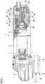
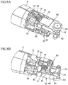
- FIG. 1 shows an example of a grinder.
- a gear housing 3 that is therein provided with a rotation transmission mechanism (not shown) that uses bevel gears and the like is assembled to the front of a cylindrical motor housing 2 that accommodates a motor described later.
- a spindle 4 projects below the gear housing 3, and a disk-shaped grindstone 5 is orthogonally connected to a lower end of the spindle 4.
- Reference numeral 6 denotes a grindstone cover that is assembled to a lower surface of the gear housing 3 and covers a rearward portion of the grindstone 5.
- Reference numeral 7 denotes a slide button that is provided on a side surface of the motor housing 2
- reference numeral 8 denotes a bottomed cylindrical rear cover that is coaxially assembled to a rear end of the motor housing 2.
- a bearing portion 9 that projects into the rear cover 8 and axially supports a rear end of an armature 26 of the motor is integratedly formed at the rear of the motor housing 2.
- four guide ribs 10 shaped as rectangular cylinders are disposed parallel to an axis line of the motor housing 2.
- a pair of brush holders 11, 11 are provided between the guide ribs 10, 10 at positions symmetrical about a point centered on the bearing portion 9.
- upper and lower partition walls 12, 12 that partition the guide ribs 10 and the brush holders 11 from each other at positions symmetrical about a point centered on the bearing portion 9 are each formed with an engagement groove 13 in the up-down direction.
- a screw mounting boss 14 is provided extending toward a rear portion of the rear cover 8 and threadably fixed to a rear surface of the rear cover 8.
- Left and right side surfaces of the screw mounting boss 14 are connectably provided so as to have a flat plate configuration with reinforcement ribs 15, 15' that hold the screw mounting boss 14 therebetween.
- a small rib 16 shaped as a rectangular plate is provided as a holding portion that extends from a left end of the rear surface of the bearing portion 9 to an upper surface of the left reinforcement rib 15.
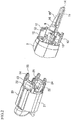
- the guide ribs 10 correspond to the cylindrical member described earlier in JP-2009-154271A , and each is inserted with and connects female terminals 25 provided on a stator 20 of the motor and male terminals 45 provided on a switch block 30 shown in FIG. 3 with each other.
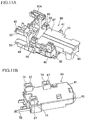
- the stator 20 of the motor includes a terminal member 23 that has on a rear end surface thereof an iron core 21 around which coils 22 are wound.
- the terminal member 23 is integratedly formed with four front insertion portions 24 that respectively accommodate the female terminals 25 connected to the coils 22 and face rearward.
- Inserting the stator 20 from a front opening of the motor housing 2 enables the stator 20 to be positioned by contacting a positioning stepped portion (not shown) that is provided on an inner surface of the motor housing 2.
- the front insertion portions 24 are respectively inserted from the front into the corresponding guide ribs 10.
- a rear end of the armature 26 is axially supported by the bearing portion 9 as shown in FIG. 1 .
- the switch block 30 is a molded component made of synthetic resin.
- the switch block 30 includes a base portion 31 shaped as a rectangle plate in a frontal view, and the center of a front portion of the switch block 30 is formed with a through-hole 32 into which the bearing portion 9 is fitted.
- the front of the base portion 31 includes four rear insertion portions 33 that correspond to the guide ribs 10, and a pair of engagement sections 34 that are provided at upper and lower positions symmetrical about a point centered on the through-hole 32 and that engage with the engagement grooves 13 provided in the motor housing 2.
- Reference numerals 35 each denote a terminal that connects to a brush.
- a lower side of the base portion 31 is provided with an engagement plate 36 that forms part of the through-hole 32.
- the engagement plate 36 is formed with a pair of left and right engagement holes 37, and a fitting hole 38 that is located between the two engagement holes 37.
- a main body portion 39 that incorporates a switch 40 and a switch board 42 is formed above the through-hole 32, and a lever 41 of the switch 40 projects from a left surface of the main body portion 39.
- a receiving seat 43 is projectingly provided on a rear end of the main body portion 39, and fixes a power cord 44 that is drawn inside from the rear portion of the rear cover 8.
- the rear insertion portions 33 are respectively provided with the male terminals 45 that are respectively inserted with and connected to the female terminals 25 of the stator 20, except for the lower left rear insertion portion (indicated as 33A in order to distinguish from the other rear insertion portions).
- the rear insertion portion 33A is formed with a through-hole 46 that longitudinally runs through the rear insertion portion 33A.
- the rear insertion portion 33A serves as a positioning portion of a controller terminal described later.
- a lower surface of the main body portion 39 is provided with an assembling seat 47 of a controller 60.
- the assembling seat 47 includes three connection portions 48 that project downward and are provided at three locations: positions to the left and right of the through-hole 32 along a rear surface of the base portion 31, and a longitudinally center position on the right side of the main body portion 39 between the rear surface of the base portion 31 and the rear of the switch block 30.
- the connection portions 48 each accommodate a female terminal 49 (shown in FIG. 6 ) that opens rearward, and rear and lower surfaces of each connection portion 48 are formed with a slit 50 that serves as an entry opening of a terminal plate 67 described later.
- the assembling seat 47 further includes a receiving projection 51 that is provided projecting to the same height as the connection portion 48 at the longitudinally center position on the left side of the main body portion 39; and reverse L-shaped rail projections 52 that are provided projecting downward on the left and right sides of the main body portion 39 rearward of the receiving projection 51, and whose engagement side faces outward.
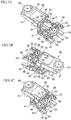
- the rear and lower surfaces of each connection portion 48 that serve as formation surfaces of the slit 50 are recessed portions 53, 54 that are lower than left and right ends of each connection portion 48.
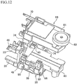
- the controller 60 to be assembled here incorporates a substrate 62 that forms a control circuit into a flat rectangular box 61.
- a rear portion of the box 61 is provided with a speed adjustment dial 63 that partially projects rearward of the box 61.
- a front surface of the box 61 includes a pair of left and right hooks 64 that engage with the engagement holes 37 provided on the engagement plate 36 of the base portion 31; and a fitting projection 65 that is positioned between the hooks 64 and inserted into the fitting hole 38 when assembled to the switch block 30.
- an upper surface of the box 61 is provided with a pair of left and right L-shaped engagement projections 66 that engage from an outer side with the rail projections 52 provided on the assembling seat 47 when assembled to the switch block 30.
- each terminal plate 67 that serve as male terminals from the substrate 62 connected to the switch block 30 are provided longitudinally projecting at positions corresponding to each female terminal 49 of the switch block 30.
- a rectangular first projection 68 is projectingly provided adjacent to the terminal plate 67 so as to fit to the recessed portion 53 on the rear surface side of the connection portion 48 of the switch block 30, when the terminal plate 67 and the female terminal 49 are connected.
- a rectangular second projection 69 is formed so as to fit to the recessed portion 54 on the lower surface side of the connection portion 48, when the terminal plate 67 and the female terminal 49 are connected.
- Reference numeral 70 denotes a controller terminal that projects forward from the left side of the front surface of the box 61, and penetrates the through-hole 46 of the rear insertion portion 33Awhen assembled to the switch block 30.
- each terminal plate 67 enters inside the corresponding connection portion 48 from the slits 50, which are on the rear surfaces of the forwardly positioned connection portions 48, and inserted with and connected to the corresponding female terminal 49.
- the first projection 68 and the second projection 69 on each terminal plate 67 side are fitted to the recessed portion 53 and the recessed portion 54 of the corresponding connection portion 48, respectively, such that the recessed portions 53, 54 are blocked.
- the engagement projections 66 of the box 61 are engaged with the rail projections 52 of the assembling seat 47, and the hooks 64 are engaged with the engagement holes 37 of the engagement plate 36 to insert the fitting projection 65 into the fitting hole 38.
- the controller terminal 70 runs through the through-hole 46 of the rear insertion portion 33A.
- the guide ribs 10 of the motor housing 2 are aligned with the positions of the rear insertion portions 33 of the switch block 30 so that the switch block 30 slides forward. Accordingly, as shown in FIGS. 8A and 8B , the screw mounting boss 14 of the motor housing 2 runs through the through-hole 32 of the switch block 30 and passes between the main body portion 39 and the controller 60.
- the rear insertion portions 33 are respectively inserted into the guide ribs 10, and the male terminals 45 and the controller terminal 70 are each inserted into and connected to the female terminals 25 on the stator side.
- the small rib 16 provided on the reinforcement rib 15 is positioned on a front surface of the switch 40 and restricts movement in a direction of release from the switch block 30 of the switch 40.
- a slide lever 17 is provided that connects the lever 41 of the switch 40 and the slide button 7.
- the power cord 44 is connected to the switch block 30, and the rear cover 8 is then assembled.
- a screw (not shown) is threadedly fastened to the screw mounting boss 14, assembly of the grinder 1 as shown in FIG. 1 is complete.
- the dial 63 of the controller 60 passes through a window 18 provided at the rear portion of the rear cover 8 so as to be partially exposed.
- the terminal plates 67 are projectingly provided on an upper surface that serves as an assembling surface of the controller 60.
- the connection portions 48 which accommodate the female terminals 49 and includes the slits 50 into which the terminal plates 67 respectively enter, are projectingly provided on the lower surface of the main body portion 39 that serves as an assembling surface of the switch block 30.
- the terminal plates 67 that respectively enter into the connection portions 48 from the slits 50 are inserted into and connected to the female terminals 49.
- the first and second projections 68, 69 are formed on the upper surface of the controller 60 so as to cover the formation surfaces of the slit 50 in each connection portion 48 when the corresponding terminal plate 67 is in an inserted and connected state. Accordingly, suitable dust resistance can be achieved between the terminals of the switch block 30 and the controller 60 assembled in a narrow space.
- the connection operation can thus employ a simple insertable connection so that the assembly operation can be performed in a short time at low cost.
- the controller 60 is provided with the controller terminal 70 that is electrically connected to the motor side through the switch block 30.
- the switch block 30 is provided with the rear insertion portion 33A that positions the controller terminal 70 at a position of connection with the motor side at the time of assembling of the controller 60. Therefore, even with the switch block 30 interposed therebetween, the controller terminal 70 can be electrically connected to the motor side in a precise and reliable manner.
- the motor housing 2 is formed with the small rib 16 that prevents detachment of the switch 40 from the switch block 30 by contacting the outer surface of the switch 40 at the time of assembling of the switch block 30. Therefore, an efficient structure is achieved in which the switch 40 is automatically held in the assembled state of the switch block 30.
- first and second projections 68, 69 are used as closing portions that are provided adjacent to each terminal plate 67, and respectively fit to the recessed portions 53, 54 that are provided recessed on the formation surfaces of the slit 50. Accordingly, inter-terminal dust resistance is made possible with a minimal structure that requires few design changes.
- the two projections that serve as closing portions are provided so as to respectively fit to recessed portions provided on the rear and lower surfaces of each connection portion.
- the projection and the recessed portion that fit together in the up-down direction may be omitted.
- the assembly structure of the switch block and the controller is also not limited to the embodiment described above. Appropriate design changes may be made within the scope of the appended claims, such as reversing the upper and lower positions of the controller and the main body portion of the switch block, and providing the rail projections and the engagement projections in a reverse configuration, for example.
- the upper surface of the box 61 of the controller 60 may be provided with a closing portion 71 that is C-shaped in a plane view.
- the closing portion 71 is formed from a rear plate 72 that is adjacent to a rear end of each terminal plate 67 and contacts a rear surface of the corresponding connection portion 48 when connected to the switch block 30, and a pair of side plates 73 that are provided continuing forward from both ends of the rear plate 72 and contact side surfaces of the corresponding connection portion 48 when connected to the switch block 30.
- connection portion 48 high dust resistance can be obtained because the rear surface as well as the left and right side surfaces of the connection portion 48 are widely covered. Note that although fitting of the recessed portion 54 and the second projection 69 on an upper side of the terminal plate 67 remains unchanged here, this fitting may be omitted and only the closing portion 71 employed.
- the direction in which the controller is assembled to the switch block is not limited to sliding in the longitudinal direction as described in the above embodiment.
- the assembling direction may be a vertical or lateral direction, and the form of the closing portion may be modified in accordance with the assembling direction in such case.
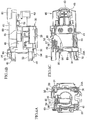
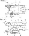
- FIGS. 11A to 13B illustrate a modification when the controller 60 is assembled to the switch block 30 in the vertical direction.
- each connection portion 48 that is provided on the assembling seat 47 of the switch block 30 is a rectangular projection that provides the slit 50 on only a lower surface thereof and accommodates the female terminal 49 facing downward.
- the periphery of each terminal plate 67 projectingly provided on the upper surface of the controller 60 is provided with a closing portion 74 shaped as a rectangular cylinder.
- Each closing portion 74 is externally fitted to the corresponding connection portion 48 and covers four surfaces, namely, the front, rear, left, and right surfaces, of the connection portion 48 when assembled to the switch block 30.
- each closing portion 74 of the controller 60 faces opposite the corresponding connection portion 48 of the switch block 30.
- high dust resistance can be obtained because the periphery of each connection portion 48 is covered by the corresponding closing portion 74 as shown in FIGS. 13A and 13B .
- the female terminals are provided on the switch block and the male terminals are provided on the controller in the embodiment and modifications described above, these terminals including the connection portions and the closing portions may be provided in a reverse configuration.
- the screw mounting boss that passes between the switch block and the controller may be omitted, and the positions and sizes of the connection portions, the receiving projection, and the rail projections may also be modified.
Applications Claiming Priority (1)
| Application Number | Priority Date | Filing Date | Title |
|---|---|---|---|
| JP2010107501A JP5468459B2 (ja) | 2010-05-07 | 2010-05-07 | グラインダ |
Publications (3)
| Publication Number | Publication Date |
|---|---|
| EP2384855A2 EP2384855A2 (en) | 2011-11-09 |
| EP2384855A3 EP2384855A3 (en) | 2013-11-13 |
| EP2384855B1 true EP2384855B1 (en) | 2017-06-14 |
Family
ID=44279166
Family Applications (1)
| Application Number | Title | Priority Date | Filing Date |
|---|---|---|---|
| EP11162928.3A Active EP2384855B1 (en) | 2010-05-07 | 2011-04-19 | Grinder with improved connection between controller and switch block for better protection against grinding dust |
Country Status (6)
| Country | Link |
|---|---|
| US (1) | US8657033B2 (zh) |
| EP (1) | EP2384855B1 (zh) |
| JP (1) | JP5468459B2 (zh) |
| CN (1) | CN102233543A (zh) |
| BR (1) | BRPI1101855B1 (zh) |
| RU (1) | RU2564496C2 (zh) |
Cited By (2)
| Publication number | Priority date | Publication date | Assignee | Title |
|---|---|---|---|---|
| DE102019134135A1 (de) * | 2019-12-12 | 2021-06-17 | Metabowerke Gmbh | Vorrichtung zur Verbindung eines Netzkabels |
| US11837935B2 (en) | 2021-02-02 | 2023-12-05 | Black & Decker, Inc. | Canned brushless motor |
Families Citing this family (9)
| Publication number | Priority date | Publication date | Assignee | Title |
|---|---|---|---|---|
| JP6045380B2 (ja) | 2013-02-08 | 2016-12-14 | リョービ株式会社 | 縦型電動工具 |
| US9954418B2 (en) | 2014-03-17 | 2018-04-24 | Makita Corporation | Power tool |
| JP6717124B2 (ja) * | 2015-12-29 | 2020-07-01 | 工機ホールディングス株式会社 | 電動工具 |
| DE102016222532A1 (de) | 2016-11-16 | 2018-05-17 | Robert Bosch Gmbh | Elektrische Maschine mit einem Bürstenhalter-Bauteil und einem Steckermodul |
| JP6874481B2 (ja) * | 2017-03-31 | 2021-05-19 | 工機ホールディングス株式会社 | 電動工具 |
| US11007632B2 (en) * | 2017-12-01 | 2021-05-18 | Makita Corporation | Power tool |
| JP7210261B2 (ja) | 2018-12-14 | 2023-01-23 | 株式会社マキタ | 電動作業機及び電動作業機用モータにおけるステータの製造方法 |
| JP2021126708A (ja) * | 2020-02-10 | 2021-09-02 | 株式会社マキタ | 電動工具用コントローラ及び電動工具 |
| JP2023055115A (ja) | 2021-10-05 | 2023-04-17 | 株式会社マキタ | 電動工具 |
Family Cites Families (15)
| Publication number | Priority date | Publication date | Assignee | Title |
|---|---|---|---|---|
| JPS5761480A (en) * | 1980-09-26 | 1982-04-13 | Hitachi Koki Kk | Motor tool |
| US4673837A (en) * | 1984-05-11 | 1987-06-16 | Amp Incorporated | Motor brush assembly |
| ATE116490T1 (de) | 1989-07-15 | 1995-01-15 | Kress Elektrik Gmbh & Co | Elektrowerkzeug. |
| RU2032520C1 (ru) * | 1990-10-01 | 1995-04-10 | Казанский Авиационный Институт Им.А.Н.Туполева | Шлифовальная ручная машина |
| JP3148450B2 (ja) * | 1993-01-28 | 2001-03-19 | 株式会社マキタ | 内部配線がブロック化された携帯用電動工具とその組付方法 |
| JPH08290371A (ja) * | 1995-02-23 | 1996-11-05 | Makita Corp | 電動工具におけるバッテリーパックの接続構造 |
| RU2152862C2 (ru) * | 1998-08-10 | 2000-07-20 | Закрытое Акционерное Общество "Энерпред" | Ручная шлифовальная машина |
| JP3672774B2 (ja) * | 1999-10-12 | 2005-07-20 | 株式会社マキタ | 携帯用電動工具における電装品の装着構造 |
| DE20000223U1 (de) * | 2000-01-10 | 2001-05-23 | Bosch Gmbh Robert | Winkelschleifer mit Elektroantrieb |
| DE10347943B4 (de) * | 2003-10-15 | 2018-08-23 | Robert Bosch Gmbh | Elektrowerkzeugmaschine |
| US7597157B2 (en) * | 2004-09-24 | 2009-10-06 | Robert Bosch Gmbh | Electric power tool having cooling conduits |
| US7551411B2 (en) | 2005-10-12 | 2009-06-23 | Black & Decker Inc. | Control and protection methodologies for a motor control module |
| DE102006022996A1 (de) * | 2006-05-17 | 2007-11-22 | Robert Bosch Gmbh | Elektrische Netzschlusseinrichtung für ein Elektrohandwerkzeug |
| JP5001824B2 (ja) | 2007-12-27 | 2012-08-15 | 株式会社マキタ | 電動工具 |
| JP5323364B2 (ja) | 2008-02-15 | 2013-10-23 | 株式会社マキタ | 電動工具 |
-
2010
- 2010-05-07 JP JP2010107501A patent/JP5468459B2/ja active Active
-
2011
- 2011-04-18 US US13/088,848 patent/US8657033B2/en active Active
- 2011-04-19 EP EP11162928.3A patent/EP2384855B1/en active Active
- 2011-04-26 BR BRPI1101855-0A patent/BRPI1101855B1/pt active IP Right Grant
- 2011-05-05 CN CN2011101173288A patent/CN102233543A/zh active Pending
- 2011-05-06 RU RU2011118417/02A patent/RU2564496C2/ru active
Non-Patent Citations (1)
| Title |
|---|
| None * |
Cited By (8)
| Publication number | Priority date | Publication date | Assignee | Title |
|---|---|---|---|---|
| DE102019134135A1 (de) * | 2019-12-12 | 2021-06-17 | Metabowerke Gmbh | Vorrichtung zur Verbindung eines Netzkabels |
| EP3842187A1 (de) | 2019-12-12 | 2021-06-30 | Metabowerke GmbH | Vorrichtung zur verbindung eines netzkabels |
| US11387599B2 (en) | 2019-12-12 | 2022-07-12 | Metabowerke Gmbh | Apparatus for connecting a power cable |
| US11837935B2 (en) | 2021-02-02 | 2023-12-05 | Black & Decker, Inc. | Canned brushless motor |
| US11855521B2 (en) | 2021-02-02 | 2023-12-26 | Black & Decker, Inc. | Brushless DC motor for a body-grip power tool |
| US11870316B2 (en) | 2021-02-02 | 2024-01-09 | Black & Decker, Inc. | Brushless motor including a nested bearing bridge |
| US11876424B2 (en) | 2021-02-02 | 2024-01-16 | Black & Decker Inc. | Compact brushless motor including in-line terminals |
| US11955863B2 (en) | 2021-02-02 | 2024-04-09 | Black & Decker Inc. | Circuit board assembly for compact brushless motor |
Also Published As
| Publication number | Publication date |
|---|---|
| RU2564496C2 (ru) | 2015-10-10 |
| BRPI1101855B1 (pt) | 2020-09-15 |
| RU2011118417A (ru) | 2012-11-20 |
| EP2384855A3 (en) | 2013-11-13 |
| EP2384855A2 (en) | 2011-11-09 |
| BRPI1101855A2 (pt) | 2012-11-20 |
| CN102233543A (zh) | 2011-11-09 |
| US8657033B2 (en) | 2014-02-25 |
| JP5468459B2 (ja) | 2014-04-09 |
| US20110272264A1 (en) | 2011-11-10 |
| JP2011235376A (ja) | 2011-11-24 |
Similar Documents
| Publication | Publication Date | Title |
|---|---|---|
| EP2384855B1 (en) | Grinder with improved connection between controller and switch block for better protection against grinding dust | |
| US9136744B2 (en) | Electric motor with reduced axial footprint | |
| US7859148B2 (en) | Motor having brush holder comprising brush retaining portion and base member in which brush retaining portion is loosely fit | |
| EP0057413A2 (en) | Printed circuit board and trigger-switch arrangement for a portable tool | |
| JP5666924B2 (ja) | 車両用の電気接続箱 | |
| US6623296B2 (en) | Plug socket | |
| US20090066185A1 (en) | Commutator motor utilizing existing part to restrict radially outward movement of brush holders | |
| EP1737103B1 (en) | Brushless motor | |
| WO2015098482A1 (ja) | 電気回路装置 | |
| JP2000067723A (ja) | 電磁接触器 | |
| KR101258784B1 (ko) | 자동차의 워터펌프 클러치용 일렉트릭 코일 어셈블리 | |
| JP2015125967A (ja) | 電気コネクタ | |
| KR20140059925A (ko) | 전동기용 터미널 하우징 및 이를 이용한 전동기 | |
| US9496764B2 (en) | Brush holder for an electric motor, and gear mechanism drive unit having a brush holder | |
| WO2018139248A1 (ja) | モータ装置 | |
| JP2017208945A (ja) | 直流モータ | |
| JP2006074858A (ja) | モータ | |
| JP2003079109A (ja) | ブラシホルダ及び電動モータ | |
| KR101965010B1 (ko) | 모터 및 모터의 제조방법 | |
| US20130267108A1 (en) | Card unit and card edge connector | |
| KR101800308B1 (ko) | 전기 스위치 소자, 특히 접촉기 또는 계전기용 배열체, 및 요크 부재와 코일 사이에 제어 모듈을 갖는 전기 스위치 소자 | |
| JP2011041408A (ja) | モータ | |
| JP2013207885A (ja) | モータ装置およびその組立方法 | |
| JP4777769B2 (ja) | モータ | |
| KR101350406B1 (ko) | 리테이너 체결지그 |
Legal Events
| Date | Code | Title | Description |
|---|---|---|---|
| AK | Designated contracting states |
Kind code of ref document: A2 Designated state(s): AL AT BE BG CH CY CZ DE DK EE ES FI FR GB GR HR HU IE IS IT LI LT LU LV MC MK MT NL NO PL PT RO RS SE SI SK SM TR |
|
| AX | Request for extension of the european patent |
Extension state: BA ME |
|
| PUAI | Public reference made under article 153(3) epc to a published international application that has entered the european phase |
Free format text: ORIGINAL CODE: 0009012 |
|
| PUAL | Search report despatched |
Free format text: ORIGINAL CODE: 0009013 |
|
| AK | Designated contracting states |
Kind code of ref document: A3 Designated state(s): AL AT BE BG CH CY CZ DE DK EE ES FI FR GB GR HR HU IE IS IT LI LT LU LV MC MK MT NL NO PL PT RO RS SE SI SK SM TR |
|
| AX | Request for extension of the european patent |
Extension state: BA ME |
|
| RIC1 | Information provided on ipc code assigned before grant |
Ipc: B24B 23/02 20060101AFI20131009BHEP Ipc: H02K 5/22 20060101ALI20131009BHEP Ipc: B24B 55/00 20060101ALI20131009BHEP Ipc: B25F 5/02 20060101ALI20131009BHEP Ipc: H01R 24/68 20110101ALI20131009BHEP Ipc: H02K 11/00 20060101ALI20131009BHEP Ipc: H02K 7/14 20060101ALI20131009BHEP Ipc: H01H 1/58 20060101ALI20131009BHEP Ipc: H01H 9/04 20060101ALI20131009BHEP |
|
| 17P | Request for examination filed |
Effective date: 20140417 |
|
| RBV | Designated contracting states (corrected) |
Designated state(s): AL AT BE BG CH CY CZ DE DK EE ES FI FR GB GR HR HU IE IS IT LI LT LU LV MC MK MT NL NO PL PT RO RS SE SI SK SM TR |
|
| GRAP | Despatch of communication of intention to grant a patent |
Free format text: ORIGINAL CODE: EPIDOSNIGR1 |
|
| INTG | Intention to grant announced |
Effective date: 20161208 |
|
| GRAS | Grant fee paid |
Free format text: ORIGINAL CODE: EPIDOSNIGR3 |
|
| GRAJ | Information related to disapproval of communication of intention to grant by the applicant or resumption of examination proceedings by the epo deleted |
Free format text: ORIGINAL CODE: EPIDOSDIGR1 |
|
| GRAL | Information related to payment of fee for publishing/printing deleted |
Free format text: ORIGINAL CODE: EPIDOSDIGR3 |
|
| INTC | Intention to grant announced (deleted) | ||
| GRAR | Information related to intention to grant a patent recorded |
Free format text: ORIGINAL CODE: EPIDOSNIGR71 |
|
| GRAA | (expected) grant |
Free format text: ORIGINAL CODE: 0009210 |
|
| AK | Designated contracting states |
Kind code of ref document: B1 Designated state(s): AL AT BE BG CH CY CZ DE DK EE ES FI FR GB GR HR HU IE IS IT LI LT LU LV MC MK MT NL NO PL PT RO RS SE SI SK SM TR |
|
| INTG | Intention to grant announced |
Effective date: 20170505 |
|
| REG | Reference to a national code |
Ref country code: GB Ref legal event code: FG4D |
|
| REG | Reference to a national code |
Ref country code: CH Ref legal event code: EP Ref country code: AT Ref legal event code: REF Ref document number: 900506 Country of ref document: AT Kind code of ref document: T Effective date: 20170615 |
|
| REG | Reference to a national code |
Ref country code: IE Ref legal event code: FG4D |
|
| REG | Reference to a national code |
Ref country code: DE Ref legal event code: R096 Ref document number: 602011038643 Country of ref document: DE |
|
| REG | Reference to a national code |
Ref country code: NL Ref legal event code: MP Effective date: 20170614 |
|
| REG | Reference to a national code |
Ref country code: LT Ref legal event code: MG4D |
|
| PG25 | Lapsed in a contracting state [announced via postgrant information from national office to epo] |
Ref country code: ES Free format text: LAPSE BECAUSE OF FAILURE TO SUBMIT A TRANSLATION OF THE DESCRIPTION OR TO PAY THE FEE WITHIN THE PRESCRIBED TIME-LIMIT Effective date: 20170614 Ref country code: NO Free format text: LAPSE BECAUSE OF FAILURE TO SUBMIT A TRANSLATION OF THE DESCRIPTION OR TO PAY THE FEE WITHIN THE PRESCRIBED TIME-LIMIT Effective date: 20170914 Ref country code: LT Free format text: LAPSE BECAUSE OF FAILURE TO SUBMIT A TRANSLATION OF THE DESCRIPTION OR TO PAY THE FEE WITHIN THE PRESCRIBED TIME-LIMIT Effective date: 20170614 Ref country code: HR Free format text: LAPSE BECAUSE OF FAILURE TO SUBMIT A TRANSLATION OF THE DESCRIPTION OR TO PAY THE FEE WITHIN THE PRESCRIBED TIME-LIMIT Effective date: 20170614 Ref country code: GR Free format text: LAPSE BECAUSE OF FAILURE TO SUBMIT A TRANSLATION OF THE DESCRIPTION OR TO PAY THE FEE WITHIN THE PRESCRIBED TIME-LIMIT Effective date: 20170915 Ref country code: FI Free format text: LAPSE BECAUSE OF FAILURE TO SUBMIT A TRANSLATION OF THE DESCRIPTION OR TO PAY THE FEE WITHIN THE PRESCRIBED TIME-LIMIT Effective date: 20170614 |
|
| REG | Reference to a national code |
Ref country code: AT Ref legal event code: MK05 Ref document number: 900506 Country of ref document: AT Kind code of ref document: T Effective date: 20170614 |
|
| PG25 | Lapsed in a contracting state [announced via postgrant information from national office to epo] |
Ref country code: LV Free format text: LAPSE BECAUSE OF FAILURE TO SUBMIT A TRANSLATION OF THE DESCRIPTION OR TO PAY THE FEE WITHIN THE PRESCRIBED TIME-LIMIT Effective date: 20170614 Ref country code: BG Free format text: LAPSE BECAUSE OF FAILURE TO SUBMIT A TRANSLATION OF THE DESCRIPTION OR TO PAY THE FEE WITHIN THE PRESCRIBED TIME-LIMIT Effective date: 20170914 Ref country code: RS Free format text: LAPSE BECAUSE OF FAILURE TO SUBMIT A TRANSLATION OF THE DESCRIPTION OR TO PAY THE FEE WITHIN THE PRESCRIBED TIME-LIMIT Effective date: 20170614 Ref country code: NL Free format text: LAPSE BECAUSE OF FAILURE TO SUBMIT A TRANSLATION OF THE DESCRIPTION OR TO PAY THE FEE WITHIN THE PRESCRIBED TIME-LIMIT Effective date: 20170614 Ref country code: SE Free format text: LAPSE BECAUSE OF FAILURE TO SUBMIT A TRANSLATION OF THE DESCRIPTION OR TO PAY THE FEE WITHIN THE PRESCRIBED TIME-LIMIT Effective date: 20170614 |
|
| PG25 | Lapsed in a contracting state [announced via postgrant information from national office to epo] |
Ref country code: CZ Free format text: LAPSE BECAUSE OF FAILURE TO SUBMIT A TRANSLATION OF THE DESCRIPTION OR TO PAY THE FEE WITHIN THE PRESCRIBED TIME-LIMIT Effective date: 20170614 Ref country code: RO Free format text: LAPSE BECAUSE OF FAILURE TO SUBMIT A TRANSLATION OF THE DESCRIPTION OR TO PAY THE FEE WITHIN THE PRESCRIBED TIME-LIMIT Effective date: 20170614 Ref country code: AT Free format text: LAPSE BECAUSE OF FAILURE TO SUBMIT A TRANSLATION OF THE DESCRIPTION OR TO PAY THE FEE WITHIN THE PRESCRIBED TIME-LIMIT Effective date: 20170614 Ref country code: EE Free format text: LAPSE BECAUSE OF FAILURE TO SUBMIT A TRANSLATION OF THE DESCRIPTION OR TO PAY THE FEE WITHIN THE PRESCRIBED TIME-LIMIT Effective date: 20170614 Ref country code: SK Free format text: LAPSE BECAUSE OF FAILURE TO SUBMIT A TRANSLATION OF THE DESCRIPTION OR TO PAY THE FEE WITHIN THE PRESCRIBED TIME-LIMIT Effective date: 20170614 |
|
| PG25 | Lapsed in a contracting state [announced via postgrant information from national office to epo] |
Ref country code: IT Free format text: LAPSE BECAUSE OF FAILURE TO SUBMIT A TRANSLATION OF THE DESCRIPTION OR TO PAY THE FEE WITHIN THE PRESCRIBED TIME-LIMIT Effective date: 20170614 Ref country code: SM Free format text: LAPSE BECAUSE OF FAILURE TO SUBMIT A TRANSLATION OF THE DESCRIPTION OR TO PAY THE FEE WITHIN THE PRESCRIBED TIME-LIMIT Effective date: 20170614 Ref country code: PL Free format text: LAPSE BECAUSE OF FAILURE TO SUBMIT A TRANSLATION OF THE DESCRIPTION OR TO PAY THE FEE WITHIN THE PRESCRIBED TIME-LIMIT Effective date: 20170614 Ref country code: IS Free format text: LAPSE BECAUSE OF FAILURE TO SUBMIT A TRANSLATION OF THE DESCRIPTION OR TO PAY THE FEE WITHIN THE PRESCRIBED TIME-LIMIT Effective date: 20171014 |
|
| REG | Reference to a national code |
Ref country code: DE Ref legal event code: R097 Ref document number: 602011038643 Country of ref document: DE |
|
| PLBE | No opposition filed within time limit |
Free format text: ORIGINAL CODE: 0009261 |
|
| STAA | Information on the status of an ep patent application or granted ep patent |
Free format text: STATUS: NO OPPOSITION FILED WITHIN TIME LIMIT |
|
| PG25 | Lapsed in a contracting state [announced via postgrant information from national office to epo] |
Ref country code: DK Free format text: LAPSE BECAUSE OF FAILURE TO SUBMIT A TRANSLATION OF THE DESCRIPTION OR TO PAY THE FEE WITHIN THE PRESCRIBED TIME-LIMIT Effective date: 20170614 |
|
| 26N | No opposition filed |
Effective date: 20180315 |
|
| PG25 | Lapsed in a contracting state [announced via postgrant information from national office to epo] |
Ref country code: SI Free format text: LAPSE BECAUSE OF FAILURE TO SUBMIT A TRANSLATION OF THE DESCRIPTION OR TO PAY THE FEE WITHIN THE PRESCRIBED TIME-LIMIT Effective date: 20170614 |
|
| PG25 | Lapsed in a contracting state [announced via postgrant information from national office to epo] |
Ref country code: MC Free format text: LAPSE BECAUSE OF FAILURE TO SUBMIT A TRANSLATION OF THE DESCRIPTION OR TO PAY THE FEE WITHIN THE PRESCRIBED TIME-LIMIT Effective date: 20170614 |
|
| REG | Reference to a national code |
Ref country code: CH Ref legal event code: PL |
|
| REG | Reference to a national code |
Ref country code: BE Ref legal event code: MM Effective date: 20180430 |
|
| GBPC | Gb: european patent ceased through non-payment of renewal fee |
Effective date: 20180419 |
|
| REG | Reference to a national code |
Ref country code: IE Ref legal event code: MM4A |
|
| PG25 | Lapsed in a contracting state [announced via postgrant information from national office to epo] |
Ref country code: LU Free format text: LAPSE BECAUSE OF NON-PAYMENT OF DUE FEES Effective date: 20180419 |
|
| PG25 | Lapsed in a contracting state [announced via postgrant information from national office to epo] |
Ref country code: GB Free format text: LAPSE BECAUSE OF NON-PAYMENT OF DUE FEES Effective date: 20180419 Ref country code: BE Free format text: LAPSE BECAUSE OF NON-PAYMENT OF DUE FEES Effective date: 20180430 Ref country code: CH Free format text: LAPSE BECAUSE OF NON-PAYMENT OF DUE FEES Effective date: 20180430 Ref country code: LI Free format text: LAPSE BECAUSE OF NON-PAYMENT OF DUE FEES Effective date: 20180430 |
|
| PG25 | Lapsed in a contracting state [announced via postgrant information from national office to epo] |
Ref country code: IE Free format text: LAPSE BECAUSE OF NON-PAYMENT OF DUE FEES Effective date: 20180419 Ref country code: FR Free format text: LAPSE BECAUSE OF NON-PAYMENT OF DUE FEES Effective date: 20180430 |
|
| PG25 | Lapsed in a contracting state [announced via postgrant information from national office to epo] |
Ref country code: MT Free format text: LAPSE BECAUSE OF NON-PAYMENT OF DUE FEES Effective date: 20180419 |
|
| PG25 | Lapsed in a contracting state [announced via postgrant information from national office to epo] |
Ref country code: TR Free format text: LAPSE BECAUSE OF FAILURE TO SUBMIT A TRANSLATION OF THE DESCRIPTION OR TO PAY THE FEE WITHIN THE PRESCRIBED TIME-LIMIT Effective date: 20170614 |
|
| PG25 | Lapsed in a contracting state [announced via postgrant information from national office to epo] |
Ref country code: PT Free format text: LAPSE BECAUSE OF FAILURE TO SUBMIT A TRANSLATION OF THE DESCRIPTION OR TO PAY THE FEE WITHIN THE PRESCRIBED TIME-LIMIT Effective date: 20170614 Ref country code: HU Free format text: LAPSE BECAUSE OF FAILURE TO SUBMIT A TRANSLATION OF THE DESCRIPTION OR TO PAY THE FEE WITHIN THE PRESCRIBED TIME-LIMIT; INVALID AB INITIO Effective date: 20110419 |
|
| PG25 | Lapsed in a contracting state [announced via postgrant information from national office to epo] |
Ref country code: MK Free format text: LAPSE BECAUSE OF NON-PAYMENT OF DUE FEES Effective date: 20170614 Ref country code: CY Free format text: LAPSE BECAUSE OF FAILURE TO SUBMIT A TRANSLATION OF THE DESCRIPTION OR TO PAY THE FEE WITHIN THE PRESCRIBED TIME-LIMIT Effective date: 20170614 |
|
| PG25 | Lapsed in a contracting state [announced via postgrant information from national office to epo] |
Ref country code: AL Free format text: LAPSE BECAUSE OF FAILURE TO SUBMIT A TRANSLATION OF THE DESCRIPTION OR TO PAY THE FEE WITHIN THE PRESCRIBED TIME-LIMIT Effective date: 20170614 |
|
| PGFP | Annual fee paid to national office [announced via postgrant information from national office to epo] |
Ref country code: DE Payment date: 20230228 Year of fee payment: 13 |