EP2383484A2 - Zentrifugale Schuh-Kupplungsstruktur - Google Patents
Zentrifugale Schuh-Kupplungsstruktur Download PDFInfo
- Publication number
- EP2383484A2 EP2383484A2 EP11163120A EP11163120A EP2383484A2 EP 2383484 A2 EP2383484 A2 EP 2383484A2 EP 11163120 A EP11163120 A EP 11163120A EP 11163120 A EP11163120 A EP 11163120A EP 2383484 A2 EP2383484 A2 EP 2383484A2
- Authority
- EP
- European Patent Office
- Prior art keywords
- clutch
- drum portion
- centrifugal
- clutch outer
- centrifugal shoe
- Prior art date
- Legal status (The legal status is an assumption and is not a legal conclusion. Google has not performed a legal analysis and makes no representation as to the accuracy of the status listed.)
- Granted
Links
- 230000002093 peripheral effect Effects 0.000 claims abstract description 36
- 229910001018 Cast iron Inorganic materials 0.000 claims abstract description 21
- 239000000463 material Substances 0.000 claims abstract description 20
- 238000005266 casting Methods 0.000 claims abstract description 19
- OKTJSMMVPCPJKN-UHFFFAOYSA-N Carbon Chemical compound [C] OKTJSMMVPCPJKN-UHFFFAOYSA-N 0.000 claims description 28
- 229910002804 graphite Inorganic materials 0.000 claims description 28
- 239000010439 graphite Substances 0.000 claims description 28
- 229910001141 Ductile iron Inorganic materials 0.000 claims description 12
- 239000012784 inorganic fiber Substances 0.000 claims description 7
- 239000011347 resin Substances 0.000 claims description 7
- 229920005989 resin Polymers 0.000 claims description 7
- 229920001187 thermosetting polymer Polymers 0.000 claims description 7
- 238000003754 machining Methods 0.000 claims description 6
- 230000005540 biological transmission Effects 0.000 description 51
- 230000000694 effects Effects 0.000 description 41
- 238000002485 combustion reaction Methods 0.000 description 24
- 230000003245 working effect Effects 0.000 description 11
- 238000000034 method Methods 0.000 description 7
- 230000001603 reducing effect Effects 0.000 description 7
- 238000013016 damping Methods 0.000 description 6
- 238000009826 distribution Methods 0.000 description 6
- 238000005299 abrasion Methods 0.000 description 5
- 230000007423 decrease Effects 0.000 description 5
- 230000001965 increasing effect Effects 0.000 description 5
- 230000004048 modification Effects 0.000 description 5
- 238000012986 modification Methods 0.000 description 5
- 239000000843 powder Substances 0.000 description 5
- 238000001816 cooling Methods 0.000 description 3
- 238000005461 lubrication Methods 0.000 description 3
- 239000002245 particle Substances 0.000 description 2
- 238000011144 upstream manufacturing Methods 0.000 description 2
- 229910001297 Zn alloy Inorganic materials 0.000 description 1
- 239000011358 absorbing material Substances 0.000 description 1
- 230000003247 decreasing effect Effects 0.000 description 1
- 238000007599 discharging Methods 0.000 description 1
- 230000002708 enhancing effect Effects 0.000 description 1
- 238000004519 manufacturing process Methods 0.000 description 1
- 239000002184 metal Substances 0.000 description 1
- 229910052751 metal Inorganic materials 0.000 description 1
- 238000003825 pressing Methods 0.000 description 1
- 125000006850 spacer group Chemical group 0.000 description 1
Images


Classifications
-
- F—MECHANICAL ENGINEERING; LIGHTING; HEATING; WEAPONS; BLASTING
- F16—ENGINEERING ELEMENTS AND UNITS; GENERAL MEASURES FOR PRODUCING AND MAINTAINING EFFECTIVE FUNCTIONING OF MACHINES OR INSTALLATIONS; THERMAL INSULATION IN GENERAL
- F16D—COUPLINGS FOR TRANSMITTING ROTATION; CLUTCHES; BRAKES
- F16D43/00—Automatic clutches
- F16D43/02—Automatic clutches actuated entirely mechanically
- F16D43/04—Automatic clutches actuated entirely mechanically controlled by angular speed
- F16D43/14—Automatic clutches actuated entirely mechanically controlled by angular speed with centrifugal masses actuating the clutching members directly in a direction which has at least a radial component; with centrifugal masses themselves being the clutching members
- F16D43/18—Automatic clutches actuated entirely mechanically controlled by angular speed with centrifugal masses actuating the clutching members directly in a direction which has at least a radial component; with centrifugal masses themselves being the clutching members with friction clutching members
-
- F—MECHANICAL ENGINEERING; LIGHTING; HEATING; WEAPONS; BLASTING
- F16—ENGINEERING ELEMENTS AND UNITS; GENERAL MEASURES FOR PRODUCING AND MAINTAINING EFFECTIVE FUNCTIONING OF MACHINES OR INSTALLATIONS; THERMAL INSULATION IN GENERAL
- F16D—COUPLINGS FOR TRANSMITTING ROTATION; CLUTCHES; BRAKES
- F16D43/00—Automatic clutches
- F16D43/02—Automatic clutches actuated entirely mechanically
- F16D43/04—Automatic clutches actuated entirely mechanically controlled by angular speed
- F16D43/14—Automatic clutches actuated entirely mechanically controlled by angular speed with centrifugal masses actuating the clutching members directly in a direction which has at least a radial component; with centrifugal masses themselves being the clutching members
- F16D2043/145—Automatic clutches actuated entirely mechanically controlled by angular speed with centrifugal masses actuating the clutching members directly in a direction which has at least a radial component; with centrifugal masses themselves being the clutching members the centrifugal masses being pivoting
-
- F—MECHANICAL ENGINEERING; LIGHTING; HEATING; WEAPONS; BLASTING
- F16—ENGINEERING ELEMENTS AND UNITS; GENERAL MEASURES FOR PRODUCING AND MAINTAINING EFFECTIVE FUNCTIONING OF MACHINES OR INSTALLATIONS; THERMAL INSULATION IN GENERAL
- F16D—COUPLINGS FOR TRANSMITTING ROTATION; CLUTCHES; BRAKES
- F16D2200/00—Materials; Production methods therefor
- F16D2200/0004—Materials; Production methods therefor metallic
- F16D2200/0008—Ferro
- F16D2200/0013—Cast iron
Definitions
- the present invention relates to a centrifugal shoe clutch structure for a centrifugal shoe clutch, which prevents what is termed as clutch squeak from occurring due to vibrations of a clutch outer.
- An object of the present invention is to provide a centrifugal shoe clutch structure: whose productivity is higher; whose costs are checked; and which is capable of reducing vibrations of the clutch outer and preventing clutch squeak.
- an invention described in claim 1 provides a centrifugal shoe clutch structure including : a clutch inner configured to rotatably hold a plurality of clutch shoes respectively including friction members, and connected to an input rotary member; and a clutch outer connected to an output rotary member, provided surrounding an outer periphery of the clutch inner, configured to be connected to the clutch inner in accordance with rotation of the clutch shoes in an outer peripheral direction due to a centrifugal force, and thereby a rotary driving force of the clutch inner being transmitted to the clutch outer, the centrifugal shoe clutch structure, wherein the clutch outer includes: a boss portion fitted to the output rotary member; a drum portion whose inner peripheral surface constitutes a cylinder-shaped friction surface configured to come into contact with the clutch shoes; and a connecting wall portion connecting the boss portion and the drum portion together, and the boss portion, the drum portion and the connecting wall portion are integrally cast by use of the same cast iron material by casting.
- the invention described in claim 2 provides the centrifugal shoe clutch structure according to claim 1, wherein in the clutch outer, a thickness of the drum portion is made thicker than a thickness of the connecting wall portion.
- the invention described in claim 3 provides the centrifugal shoe clutch structure according to claim 2, wherein a balance hole extending toward an axis of the clutch outer is processed in an outer periphery of the drum portion.
- the invention described in claim 4 provides the centrifugal shoe clutch structure according to claim 3, wherein in the balance hole, a remaining thickness between a bottom of the balance hole and the inner peripheral surface of the drum portion and a remaining thickness between an edge of the balance hole and an end surface of the drum portion both are thicker than the thickness of the connecting wall portion.
- the invention described in claim 5 provides the centrifugal shoe clutch structure according to claim 2, wherein a vibration-isolating wall extending toward an inner periphery is integrally formed on the end surface of the drum portion.
- the invention described in claim 6 provides the centrifugal shoe clutch structure according to claim 5, wherein the vibration-isolating wall is provided with a notched groove which is recessed from its inner peripheral end in the outer peripheral direction.
- the invention described in claim 7 provides the centrifugal shoe clutch structure according to claim 2, wherein the cylinder-shaped friction surface of the drum portion is provided with oblique grooves which are oriented oblique to the circumferential direction.
- the invention described in claim 8 provides the centrifugal shoe clutch structure according to claim 2, wherein the drum portion is provided with natural frequency adjusting holes which extend in an axial direction of the clutch outer.
- the invention described in claim 9 provides the centrifugal shoe clutch structure according to claim 8, wherein the natural frequency adjusting holes are provided in a way that their phases in a circumferential direction of the drum portion are set up in unequal intervals.
- the invention described in claim 10 provides the centrifugal shoe clutch structure according to any one of claims 8 and 9, wherein the natural frequency adjusting holes are provided in a portion of the drum portion, which continues to the connecting wall portion, in order that an end surface portion of the drum portion is not opened.
- the invention described in claim 11 provides the centrifugal shoe clutch structure according to any one of claims 1 to 10, wherein the friction members are those which are made by hardening paper-based inorganic fibers with a thermosetting resin, and are provided on outer peripheries of the clutch shoes, respectively.
- the invention described in claim 12 provides the centrifugal shoe clutch structure according to any one of the claims 1 to 11, wherein the cast iron material is a spheroidal graphite cast iron, and the clutch outer is formed in a way that spheroidal graphite contained therein is distributed unevenly in the circumferential direction of the drum portion.
- the invention described in claim 13 provides the centrifugal shoe clutch structure according to claim 12, wherein the cylinder-shaped friction surface of the drum portion is shaped like a cylinder by machining.
- the centrifugal shoe clutch structure of the invention of claim 1 enhances the productivity of the clutch and reduces the costs, because the boss portion, the drum portion and the connecting wall portion of the clutch outer are integrally cast by use of the same cast ion material by casting.
- things such as variation in the interference width due to strain resulting from heat of the friction between the clutch outer and the clutch shoes do not occur, as well as the vibration damping effect becomes stable.
- the clutch outer is integrally cast by casting, the shape which enhances the vibration-isolating effect can be formed easily. Accordingly, the enhanced vibration-isolating effect together with the cast iron's high vibration-reducing effect heightens the effect of preventing the clutch squeak.
- the invention of claim 2 brings about the effects of the invention of claim 1, and additionally enables only the key portion to be easily formed thicker by casting. Thereby, when the natural frequency of the clutch outer is set satisfactorily, the vibration-damping effect is enhanced, and concurrently the weight of the clutch outer is reduced.
- the invention of claim 3 brings about the effects of the invention of claim 2, as well as additionally makes it easy to process the balance holes, and reduces the vibrations attributable to the rotation of the clutch outer because the balance holes, which are configured to adjust the balance of the clutch outer, are processed in the drum portion formed thicker.
- the invention of claim 4 brings about the effects of the invention of claim 3, as well as additionally: keeps the thickness of the bottom of each balance hole in the drum portion, and the thickness between each balance hole and the end surface of the drum portion; and accordingly prevents the influence of the balancing process on the rotational strength of the clutch outer.
- the invention of claim 5 brings about the effects of the invention of claim 2, and additionally enables the vibration-isolating wall to be easily formed by casting. For this reason, the vibration-isolating wall enhances the vibration reducing effect, reinforces the drum portion, and increases the strength of the clutch outer.
- the invention of claim 6 brings about the effects of the invention of claim 5, as well as additionally enables the natural frequency of the vibration-isolating wall to be set satisfactorily by providing the notched grooves in the vibration-isolating wall, and thereby enhances and improves the strength and vibration-isolating performance of the clutch outer in a well-balanced manner.
- the vibration reducing effect is enhanced when: intervals between the notched grooves are unequalized; the vibration nodes are changed; and unbalance is adjusted by use of the balance holes.
- the invention of claim 7 brings about the effects of the invention of claim 2, as well as additionally: makes it possible to easily form the oblique grooves by casting; thereby enhances the vibration reducing effect by use of the oblique grooves, thus prevents the clutch squeak ; enables abrasion powder of the friction members of the respective clutch shoes to be discharged; stabilizes the frictional engagement force; makes it easy to control the frequency which occurs due to the sliding movement on the cylinder-shaped friction surface; and makes it easy to make a setup for avoidance of the resonance with the natural frequency of the clutch outer.
- the invention of claim 8 brings about the effects of the invention of claim 2, as well as additionally allows the natural frequency of the clutch outer to be satisfactorily set by use of the natural frequency adjusting holes, and thereby prevents the clutch squeak resulting from the resonance with the frequency which occurs due to the sliding movement on the clutch shoes during the clutch connection.
- the invention of claim 9 brings about the effects of the invention of claim 8, as well as additionally: inhibits the natural vibration of the clutch outer; more inhibits the resonance with the frequency which occurs due to the sliding movement on the clutch shoes; and more reduces the clutch squeak.
- the invention of claim 10 brings about the effects of the invention of any one of claims 8 and 9, as well as additionally decreases stress in the end surface portion of the drum portion, and prevents the clutch squeak, because of the structure in which the end surface portion thereof is closed.
- the invention of claim 11 brings about the effects of the invention of any one of claims 1 to 10, additionally can prevent the clutch squeak even though: the friction members made by hardening the paper-based inorganic fibers with the thermosetting resin generally have a relatively small coefficient of friction because of their relatively hard quality; and the clutch connection is performed at a high rotational speed for the purpose of increasing the transmission force. That is because the friction members are used together with the clutch outer which prevents the clutch squeak.
- This enables the friction members made by hardening the paper-based inorganic fibers with the thermosetting resin, which have higher wear resistance, to be used as the friction members to be provided on the outer peripheries of the clutch shoes. Accordingly, the durability of the centrifugal shoe clutch is enhanced, and the costs are reduced.
- the invention of claim 12 brings about the effects of the invention of any one of claims 1 to 11, and additionally increases the strength of the clutch outer because the spheroidal graphite cast iron is used as the cast iron material.
- the lubrication action of the spheroidal graphite which is the internal component of the clutch outer made of the spheroidal graphite cast iron, stabilizes the characteristics of the sliding of the clutch shoes on the cylinder-shaped friction surface, and thus makes it easy to control the frequency which occurs due to the sliding movement thereon, as well as accordingly makes it easy to make a setup for avoidance of the resonance with the natural frequency of the clutch outer.
- the vibration damping effect resulting from the change in the density of the spheroidal graphite depending on the locations enhances the effect of preventing the clutch squeak.
- the invention of claim 13 brings about the effects of the invention of claim 12, and additionally can keep the characteristic of preventing the clutch squeak high from the beginning of the use of the clutch because, from the beginning, the spheroidal graphite is exposed in the cylinder-shaped friction surface by machining.
- a centrifugal shoe clutch structure of an embodiment of the present invention on the basis of Figs. 1 to 18 .
- the frontward, rearward, leftward, rightward, upward, downward and other directions mentioned in the explanation of this description are based on the direction of a vehicle, such as a motorcycle, on which a power unit including a centrifugal shoe clutch structure of each embodiment is mounted.
- an arrow FR indicates the front side of the vehicle;
- an arrow LH indicates the left side of the vehicle;
- an arrow RH indicates the right side of the vehicle; and
- an arrow UP indicates the upper side of the vehicle.
- Figs. 1 to 5 are related to Embodiment 1 of the present invention.
- Fig. 1 shows a power unit 3, which is formed from an internal combustion engine 1 and a transmission system 2 connected to the internal combustion engine 1 with a centrifugal shoe clutch structure of this embodiment included in the power unit 3, in a posture in which the power unit 3 is mounted on a vehicle (not illustrated).
- the vehicle is a scooter-type motorcycle.
- the power unit 3 of this embodiment is formed from the front-located internal combustion engine 1 and the rear-located transmission system 2.
- the internal combustion engine 1 is supported by a vehicle body frame of the scooter-type motorcycle (not illustrated) in a way to be not swingable.
- the internal combustion engine 1 is a four-stroke cycle two-cylinder internal combustion engine.
- the internal combustion engine 1 makes an axis Y of a crankshaft 4 orthogonal to the frontward/rearward diction of the vehicle and thus oriented in a vehicle widthwise direction, as well as includes a cylinder unit 6 which protrudes obliquely upward from a crankcase 5 with a cylinder axis X tilted forward.
- the internal combustion engine 1 is formed from the crankcase 5 and the cylinder unit 6.
- the cylinder unit 6 is constructed by: sequentially stacking a cylinder block 7 and a cylinder head 8 on the crankcase 5 obliquely upward; integrally fastening the crankcase 5, the cylinder block 7 and the cylinder head 8 together; and putting a cylinder head cover 9 over the cylinder head 8.
- the cylinder block 7 includes paired cylinder bores 10, 10 which are in parallel with each other.
- the crankcase 5 movably and rotatably supports the crankshaft 4 connected to pistons 11, 11 by use of connecting rods 12, 12.
- the pistons 11, 11 are slidably fitted in the cylinder bores 10, 10.
- the cylinder head 8 forms combustion chambers 13, 13 between the cylinder head 8 and the cylinder block 7.
- the pistons 11, 11 face the combustion chambers 13, 13.
- the cylinder head cover 9 is connected to a portion of the cylinder head 8, which is opposite from the cylinder block 7.
- the crankcase 5 is constructed by connecting a left crankcase 5L and a right crankcase 5R together.
- a right case cover 15 is fastened to a right portion of the right crankcase 5R.
- a generator chamber 14 is formed between the right crankcase 5R and the right case cover 15.
- an outer rotor 16 is fixed to the crankshaft 4
- an inner stator 18 constitutes an AC generator 17 in cooperation with the outer rotor 16 is fixed to the right case cover 15.
- a front portion of a left rear arm 20L disposed to the left of the rear wheel 19 and a front portion of a right rear arm 20R disposed to the right of the rear wheel 19 are movably supported by the crankcase 5 in the internal combustion engine 1 in a way that the left rear arm 20L and the right rear arm 20 R are swingable upward and downward around the axis Y of the crankshaft 4.
- the rear wheel 19 is movably supported between the rear portions of the respective left and right rear arms 20L, 20R.
- the left rear arm 20L constitutes a part of a transmission case 21 which includes the transmission system 2 in its inside.
- the transmission system 2 is configured to transmit a motive power from the internal combustion engine 1 to the rear wheel 19.
- the transmission case 21 is formed from the left rear arm 20L and a cover 22 configured to cover the left rear arm 20L from its left outside.
- the cover 22 includes: a cover inner wall 23 fastened to the left rear arm 20L; and a cover outer wall 24 fastened to the cover inner wall 23 with a space interposed between the cover outer wall 24 and an outer surface of the cover inner wall 23.
- a ring-shaped supporting member 30 is fastened to a left outer surface of the left crankcase 5L in the crankcase 5 in a way that the supporting member 30 coaxially surrounds the crankshaft 4 which rotatably penetrates the left crankcase 5L and enters the transmission case 21.
- a front portion of the left rear arm 20L is movably and rotatably supported by the supporting member 30 with a ball bearing 31 interposed in between.
- the right rear arm 20R is formed from a frontal arm member 32, an intermediate arm member 33 and a rearward arm member 34.
- the frontal arm member 32 is movably supported by the crankcase 5 in a way to be swingable upward and downward.
- the intermediate arm member 33 is detachably connected to the frontal arm member 32.
- the rearward arm member 34 is detachably connected to the intermediate arm member 33.
- the frontal arm member 32 is formed in a way that the frontal arm member 32 starts at the right-side portion of the right case cover 15 and reaches the rear portion of the crankcase 5.
- a front portion of the frontal arm member 32 is movably and rotatably supported by a pivot shaft 35 with a roller bearing 36 interposed in between.
- the pivot shaft 35 is fastened to an outer surface of the right case cover 15 coaxially with the crankshaft 4.
- the intermediate arm member 33 is disposed between the internal combustion engine 1 and the rear wheel 19.
- the frontal arm member 32 is detachably connected to a right end portion of the intermediate arm member 33 by use of multiple bolts 37.
- the left rear arm 20L is detachably connected to a left end portion of the intermediate arm member 33 by use of multiple bolts 38.
- the left and right rear arms 20L, 20R are movably supported by the internal combustion engine 1 in a way that: the left and right rear arms 20L, 20R are connected together between the internal combustion engine 1 and the rear wheel 19; distortion is prevented from occurring between the left and right rear arms 20L, 20R; and the left and right rear arms 20L, 20R are swingable upward and downward around the axis Y of the crankshaft 4.
- the rearward arm member 34 of the right rear arm 20R is detachably connected to a right end portion of the intermediate arm member 33 by use of multiple bolts C39.
- the rearward arm member 34 is detachably connected to the intermediate arm member 33 in a way that: the rearward arm member 34 keeps the frontal arm member 32 connected to the left rear arm 20L with the intermediate arm member 33 interposed in between; and when the bolts C39 are removed, the rearward arm member 34 becomes detachable from the frontal arm member 32.
- the transmission system 2 is formed from a transmission 40, a deceleration gear train 41, and a centrifugal shoe clutch 80 provided between the transmission 40 and the deceleration gear train 41.
- the transmission is configured to change the speed of the motive power from the crankshaft 4 continuously.
- the deceleration gear train 41 is configured to decelerate the output of the transmission 40, and to transmit the resultant output to the rear wheel 19. Descriptions will be provided the centrifugal shoe clutch 80 later.
- the transmission 40 is of a publicly-known belt type in which : an endless belt 44 is wound between a driving pulley 42 provided to the crankshaft 4 and a driven pulley 43; and the driven pulley 43 is connected to a transmission output shaft 45 in a way to be alongside of the centrifugal shoe clutch 80.
- the transmission gear ratio can be changed from LOW to TOP continuously.
- a supporting wall 25 is fastened to the left rear arm 20L, and the transmission output shaft 45 is movably and rotatably supported by the left rear arm 20L and the supporting wall 25 with ball bearings 26, 27 interposed in between, respectively.
- the deceleration gear train 41 is provided between the transmission output shaft 45 and a final output shaft 46 which is a final output terminal of the transmission system 2, and is housed between the left rear arm 20L and the supporting wall 25.
- the final output shaft 46 is movably and rotatably supported by the left rear arm 20L with a ball bearing 47 interposed in between, as well as is movably and rotatably supported by the supporting wall 25 with a ball bearing 48 interposed in between.
- An axle 49 is coaxially and integrally connected to the final output shaft 46.
- the axle 49 penetrates a hub 50 of the rear wheel 19 attached to a right portion of an inner race of the ball bearing 47.
- the axle 49 and the hub 50 are spline-connected together in a way to be not rotatable relative to each other.
- the axle 49 is movably and rotatably supported by the rearward arm member 34 of the right rear arm 20R with a ball bearing 51 interposed in between.
- a cylinder-shaped spacer 52 configured to surround the axle 49 is installed between an inner race of the ball bearing C51 and the hub 50.
- a cooling air cleaner 53 is provided between the cover inner wall 23 and the cover outer wall 24.
- the air for cooling the transmission 40 of a belt type is introduced into the transmission case 21 from the outside of the transmission case 21 through the cooling air cleaner 53.
- a sound absorbing material 54 is provided between the cover inner wall 23 and the cover outer wall 24.
- paired intake valves 70 configured to control the air to be taken into one of combustion chambers 13, 13 are allocated to each combustion chamber 13, as well as paired exhaust valves (not illustrated) configured to control the air to be exhausted from one of the combustion chambers 13, 13 are allocated to each combustion chamber 13.
- an intake-side camshaft 71 configured to drive each intake valve 70 to open and close, as well as an exhaust-side camshaft (not illustrated) configured to drive each exhaust valve to open and close, are movably supported by the cylinder head 8 in a way that the intake-side camshaft 71 and the exhaust-side camshaft each have an axis which is parallel to the crankshaft 4.
- a chain chamber 72 facing an end of the intake-side camshaft 71 and an end of the exhaust-side camshaft is provided communicating with the generator chamber 14 through the crankcase 5, the cylinder block 7, the cylinder head 8 and the cylinder head cover 9.
- a driving sprocket 73 is integrally provided to a portion of the crankshaft 4 which corresponds to the chain chamber 72.
- An endless timing chain 75 configured to run in the chain chamber 72 is wound around a driven sprocket 74 fixed to an end of the intake-side camshaft 71, a driven sprocket (not illustrated) fixed to an end of the exhaust-side camshaft, and the driving sprocket 73.
- the driven pulley 43 constituting a part of the transmission 40 includes: a fixation-side pulley half body 56 fixed to a rotary cylinder 55 rotatable relative to the transmission output shaft 45 and coaxial with an axis Z of the transmission output shaft 45; and a movable-side pulley half body 57 capable of coming closer to and away from the fixation-side pulley half body 56.
- the movable-side pulley half body 57 is biased toward the fixation-side pulley half body 56 by a spring 58.
- the rotary cylinder 55 is disposed surrounding the transmission output shaft 45 coaxially.
- the rotary cylinder 55 is supported by the transmission output shaft 45 with a ball bearing 59 and a roller bearing 60 interposed in between in a way that: the rotary cylinder 55 is rotatable relative to the transmission output shaft 45; and the rotary cylinder 55 is immovable relative to the transmission output shaft 45 in an axial direction.
- a left end of the rotary cylinder 55 is supported by the cover inner wall 23 with a ball bearing 69 interposed in between.
- the fixation-side pulley half body 56 is connected to a flange portion 61 included in the rotary cylinder 55 by use of multiple rivets 62.
- a slidable cylinder 63 is put on an outer periphery of the rotary cylinder 55 in a way to be slidable in the axial direction.
- the movable-side pulley half body 57 is connected by use of multiple rivets 65 to a flange portion 64 included in the slidable cylinder 63.
- the slidable cylinder 63 is provided with a guide hole 66 extending long in the axial direction.
- a roller 68 supported by the rotary cylinder 55 in a way to pivot around a spindle 67 is inserted in the guide hole 66 in order to make it impossible for the slidable cylinder 63 to rotate relative to the rotary cylinder 55, and in order to make it possible for the slidable cylinder 63 to move relative to the rotary cylinder 55 in the axial direction.
- a spring bearing member 55a is put on a portion of the outer periphery of the rotary cylinder 55 which is opposite from the centrifugal shoe clutch 80.
- the spring 58 is installed between the spring bearing member 55a and a spring bearing member 63a put on the slidable cylinder 63. Because of the foregoing structure, the driven pulley 43 operates to decrease the diameter with which the endless belt 44 is wound around the driven pulley 43 according as the driving pulley 42 increases the diameter with which the endless belt 44 is wound around the driving pulley 42 in proportion to the increase in the number of revolutions of the crankshaft 4.
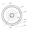
- the centrifugal shoe clutch 80 of this embodiment includes: a clutch inner 81 connected to the rotary cylinder 55 (an “input rotary member” of the present invention); and a clutch outer 82 spline-connected to the transmission output shaft 45 (an “output rotary member” of the present invention), and provided surrounding an outer peripheral portion of the clutch inner 81.
- centrifugal clutch shoes 84 for example, five centrifugal clutch shoes 84 ("clutch shoes" of the present invention) and clutch springs 85 are held by the clutch inner 81.
- Each centrifugal clutch shoe 84 includes a friction member 83 capable of frictionally engaging with the clutch outer 82, as well as is movably and rotationally supported by the clutch inner 81.
- the clutch springs 85 are configured to bias the centrifugal clutch shoes 84 in a direction in which the frictional engagement of the friction members 83 with the clutch outer 82 is released.
- the clutch outer 82 is connected to the clutch inner 81 when the centrifugal force of the rotation of the clutch inner 81 causes the clutch shoes 84 to rotationally move in the outer peripheral direction. Thus, the rotational driving force of the clutch inner 81 is transmitted to the clutch outer 82.
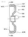
- the clutch outer 82 is formed from a boss portion 86, a drum portion 87 and a connecting wall portion 88.
- the boss portion 86 is spline-fitted to the transmission output shaft 45.
- An inner peripheral surface of the drum portion 87 constitutes a cylinder-shaped friction surface 87a configured to come into contact with the centrifugal clutch shoes 84.
- the connecting wall portion 88 connects the boss portion 86 and the drum portion 87 together.
- the boss portion 86, the drum portion 87 and the connecting wall portion 88 are integrally cast by use of the same cast iron material by casting.
- the clutch outer 82 is made of a cast iron, and is shaped almost like a bowl by integrally forming an end of the cylinder-shaped drum portion 87 in an outer periphery of the connecting wall portion 88 shaped like a circular plate.
- the cylinder-shaped boss portion 86 is integrally formed in an inner periphery of the connecting wall portion 88.
- the boss portion 86 is fixed to the transmission output shaft 45 by spline.
- the clutch outer 82 is connected to the transmission output shaft 45 serving as the output rotary member of the centrifugal shoe clutch 80.
- the cast iron material should be a spheroidal graphite cast iron.
- FCD600 or FCD700 (JIS) is used as the spheroidal graphite cast iron.
- the clutch inner 81 is shaped like a circular plate in a way to be opposed to the connecting wall portion 88 of the clutch outer 82.
- the clutch inner 81 is connected to an end portion of the rotary cylinder 55 serving the input rotary member of the centrifugal shoe clutch 80 by use of multiple bolts 89.
- Base portions of support pins 90 are fixed to multiple portions of the clutch inner 81, for example, five portions thereof, which are set up at equal intervals in a circumferential direction of the clutch inner 81.
- Each support pin 90 has an axis which is parallel with the axis Z of the transmission output shaft 45 and the rotary cylinder 55, as well as includes a collar portion 90a configured to be in slide-contact with a surface of a corresponding one of the centrifugal clutch shoes 84 which is closer to the clutch inner 81.
- the centrifugal clutch shoes 84 and a ring-shaped side plate 91 are located and housed inside the clutch outer 82.
- the side plate 91 is opposed to the portions of the centrifugal clutch shoes 84 which are opposite from the clutch inner 81.
- Retaining rings 92 to engage with the side plate 91 are fittingly attached to front end portions of the support pins 90 to be inserted in base portions of the centrifugal clutch shoes 84 and the side plate 91, respectively.
- the base portions of the centrifugal clutch shoes 84 interposed between the collar portions 90a of the support pins 90 and the side plate 91 are movably and rotatably supported by five portions of the clutch inner 81, which are set up in the circumferential direction of the clutch inner 81, by use of the support pins 90, respectively.
- the centrifugal clutch shoes 84 are rotationally movable in an outer peripheral direction and in an inner peripheral direction with respect to the axis Z of the clutch inner 81.
- the centrifugal clutch shoes 84 are made of metal such as a zinc alloy, and are shaped like a shoe. Each centrifugal clutch shoe 84 has the friction member 83 in its outer peripheral portion.
- the friction members 83 are capable of coming away from and closer to, as well as frictionally engaging with, the inner peripheral surface of the drum portion 87, that is to say, the cylinder-shaped friction surface 87a when the centrifugal clutch shoes 84 rotationally move around the support pin 90, respectively (see Figs. 1 and 3 ).
- the friction members 83 may be provided to the centrifugal clutch shoes 84 by appropriate means such as adhesion, baking, fitting and riveting, although the friction members 83 line the outer peripheral surfaces of the centrifugal clutch shoes 84 in Embodiment 1.
- the friction members 83 should be those which are obtained by hardening paper-based inorganic fibers with a thermosetting resin. It is a matter of course that the friction members 83 may be made of any other material which is usually used.
- one clutch spring 85 is suspended between a base portion 84a of one of each two neighboring centrifugal clutch shoes 84, 84 in the circumferential direction of the clutch inner 81 and an intermediate portion 84b of the other of the two neighboring centrifugal clutch shoes 84, 84 (see Fig. 1 ).
- the clutch springs 85 bias the centrifugal clutch shoes 84, respectively, in order that the centrifugal clutch shoes can rotationally move in a direction in which the friction members 83 come away from the cylinder-shaped friction surface 87a on the inner peripheral surface of the drum portion 87 of the clutch outer 82, that is to say, in the inner peripheral direction.
- the centrifugal clutch shoes 84 overcome the biasing forces of the clutch springs 85 because of the effect of the centrifugal forces which increase according as the number of revolutions of the clutch inner 81, that is to say, the number of revolutions of the rotary cylinder 55 serving as the input rotary member increases.
- the centrifugal clutch shoes 84 rotationally move in a direction in which the friction members 83 frictionally engage with the cylinder-shaped friction surface 87a of the drum portion 87, that is to say, in the outer peripheral direction. Accordingly, the clutch inner 81 and the clutch outer 82 are connected together.
- the boss portion 86, the drum portion 87 and the connecting wall portion 88 are integrally cast by use of the same cast iron material by casting.
- a thickness td of the drum portion 87 of the clutch outer 82 is made thicker than thicknesses tw1, tw2, tw3 of the connecting wall portion 88 thereof.
- Balance holes 93 for securing a rotational balance for the clutch outer 82 are processed in the outer periphery of the drum portion 87, which has the thickness td, toward the axis (center axis) Z of the clutch outer 82.
- the number of locations in which to process the balance holes 93 and the number of balance holes 93 are determined depending on the necessity (although one location is shown in the drawings).
- a remaining thickness t1 between the bottom of the balance hole 93 and the inner peripheral surface of the drum portion 87, that is to say, the cylinder-shaped friction surface 87a, as well as a remaining thickness t2 between an edge of the balance hole 93 and an end surface of the drum portion 87, are made thicker than any of the thicknesses tw1, tw2, tw3 of the connecting wall portion.
- the foregoing centrifugal shoe clutch structure of Embodiment 1 brings about the following operations/workings-effects.
- the boss portion 86, the drum portion 87 and the connecting wall portion 88 of the clutch outer 82 were integrally cast by use of the same cast iron material by casting. For this reason, the productivity of the clutch enhanced, and the costs decreased.
- the clutch outer 82 was integrally cast by casting.
- the balance holes 93 configured to adjust the balance of the clutch outer 82 were processed in the drum portion 87 formed thicker. This made it easy to process the balance holes 93, and made it possible to reduce the vibrations attributable to the rotation of the clutch outer 82. Additionally, the thickness t1 of the bottom of each balance hole 93 in the drum portion 87 and the thickness t2 between each balance hole 93 and the end surface 87b of the drum portion 87 were kept larger than predetermined. Accordingly, the influence of the balancing process on the rotational strength of the clutch outer 82 was prevented.
- the friction members 93 made by hardening the paper-based inorganic fibers with the thermosetting resin have a relatively small coefficient of friction because of their relatively hard quality, and the clutch connection is performed at a high rotational speed for the purpose of enhancing the transmission force.
- Embodiment 1 was able to prevent the clutch squeak, because the friction members 83 were used together with the clutch outer 82 which prevented the clutch squeak.
- the friction members 83 having higher wear resistance and made by hardening the paper-based inorganic fibers with the thermosetting resin were able to be used as the friction members provided to the outer peripheral portions of the clutch shoes 84. This enhanced the durability of the centrifugal shoe clutch, and reduced the costs.
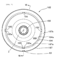
- FIGs. 6 and 7 each showing a clutch outer 182 of Embodiment 2 of the present invention alone, explanation will be provided for features of a centrifugal shoe clutch structure of Embodiment 2.
- the clutch outer 182 of Embodiment 2 is different from the clutch outer 82 of Embodiment 1.
- the rest of Embodiment 2 is virtually the same as that of Embodiment 1.
- Figs. 1 to 3 will be referred to. Duplicated illustrations and explanations will be omitted.
- components of Embodiment 2 which are the same as those of Embodiment 1 are denoted by the same reference numerals. Thereby, explanation of such components will be omitted.
- each of components of Embodiment 2 which corresponds to those of Embodiment 1 but will be explained discriminatingly is denoted by a reference numeral of one hundred and something whose last two digits are equal to the reference numeral of the corresponding component of Embodiment 1; each of components of Embodiment 2 which is completely different from those of Embodiment 1 is denoted by any other reference numeral of one hundred and something; and explanation will be provided mainly for what makes components of Embodiment 2 different from those of Embodiment 1.
- An axis of the clutch outer 182 of Embodiment 2 virtually coincides with the axis Z of the transmission output shaft 45 as in the case of Embodiment 1.
- a boss portion 186, a drum portion 187 and a connecting wall portion 188 are integrally cast by use of the same cast iron material by casting as in the case of Embodiment 1.
- the thickness td of the drum portion 187 is made thicker than any one of the thicknesses tw1, tw2, tw3 of the connecting wall portion 188 (see Fig. 4 ) as in the case of the clutch outer which has been explained with regard to Embodiment 1.
- a vibration-isolating wall 194 extending toward the inner periphery is integrally formed on an end surface 187b of the drum portion 187.
- a cylinder-shaped friction surface 187a is formed in an inner peripheral surface of the drum portion 187 between the vibration-isolating wall 194 and the connecting wall portion 188.
- the vibration-isolating wall 194 is provided with notched grooves 195 which are recessed from its inner peripheral end 194a in an outer peripheral direction.
- the positions of groove bottoms 195a of the notched grooves 195 in a radial direction of the clutch outer 182 coincide with the position of the cylinder-shaped friction surface 187a in the radial direction of the clutch outer 182.
- the positions of the groove bottoms 195a in the radial direction of the clutch outer 182 may reach a position closer to the outer periphery beyond the cylinder-shaped friction surface 187a.
- the foregoing centrifugal shoe clutch structure of Embodiment 2 brings about the same operations/workings-effects as does the centrifugal shoe clutch structure of Embodiment 1, and additionally brings about the following operations/workings-effects.
- the vibration-isolating wall 194 was able to be easily formed integrally with the clutch outer 182 by casting. For this reason, the vibration-isolating wall 194 enhanced the vibration reducing effect, reinforced the drum portion 187, and increased the strength of the clutch outer 182. Additionally, the notched grooves 195 were provided in the vibration-isolating wall 194. This made it possible to set the natural frequency of the vibration-isolating wall 194 satisfactorily, and made it easy to avoid resonance.
- the strength and vibration-isolating performance of the clutch outer 182 were enhanced and improved in a well-balanced manner.
- the number of notched grooves 195 and the size of the notched grooves 195 were able to be selected on the basis of the condition.
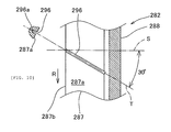
- FIGs. 8 to 10 each showing a clutch outer 282 of Embodiment 3 of the present invention alone, explanation will be provided for features of a centrifugal shoe clutch structure of Embodiment 3.
- the clutch outer 282 of Embodiment 3 is different from the clutch outer 82 of Embodiment 1.
- the rest of Embodiment 3 is virtually the same as that of Embodiment 1.
- Figs. 1 to 3 will be referred to.
- Duplicated illustrations and explanations will be omitted.
- components of Embodiment 3 which are the same as those of Embodiment 1 are denoted by the same reference numerals. Thereby, explanation of such components will be omitted.
- each of components of Embodiment 3 which corresponds to those of Embodiment 1 but will be explained discriminatingly is denoted by a reference numeral of two hundred and something whose last two digits are equal to the reference numeral of the corresponding component of Embodiment 1; each of components of Embodiment 3 which is completely different from those of Embodiment 1 is denoted by any other reference numeral of two hundred and something; and explanation will be provided mainly for what makes components of Embodiment 3 different from those of Embodiment 1.
- An axis of the clutch outer 282 of Embodiment 3 virtually coincides with the axis Z of the transmission output shaft 45 as in the case of Embodiment 1.
- a boss portion 286, a drum portion 287 and a connecting wall portion 288 are integrally cast by use of the same cast iron material by casting as in the case of Embodiment 1.
- the thickness td of the drum portion 287 is made thicker than any one of the thicknesses tw1, tw2, tw3 of the connecting wall portion 288 (see Fig. 4 ) as in the case of the clutch outer which has been explained with regard to Embodiment 1.
- oblique grooves 296 are provided in a cylinder-shaped friction surface 287a of the drum portion 287.
- Each oblique groove 296 is oriented in an illustrated T direction which is inclined at 30 ° to an illustrated S direction parallel with the axis Z of the clutch outer 282.
- the cylinder-shaped friction surface 287a is provided with the oblique grooves 296 each oriented oblique to a circumferential direction (in an illustrated R direction).
- the illustration of the oblique grooves 296 in the cylinder-shaped friction surface 287a is omitted from Fig. 8 (see Fig. 10 ).
- Fig. 10 the illustration of the oblique grooves 296 in the cylinder-shaped friction surface 287a is omitted from Fig. 8 (see Fig. 10 ).
- each oblique groove 296 causes its portion closer to the connecting wall portion 288 to be positioned in an upstream side in a rotational direction (an illustrated arrow R direction) of the clutch outer 282; traverses the cylinder-shaped friction surface 287a obliquely; and penetrates an end surface 287b of the drum portion 287 in a downstream side.
- the foregoing centrifugal shoe clutch structure of Embodiment 3 brings about the same operations/workings-effects as does the centrifugal shoe clutch structure of Embodiment 1, and additionally brings about the following operations/workings-effects.
- the oblique grooves 296 were able to be easily formed integrally with the clutch outer 282 by casting. For this reason, the oblique grooves 296 enhanced the vibration reducing effect, and the clutch squeak was prevented.
- the oblique grooves 296 made it possible to discharge abrasion powder of the friction members 83 of the respective clutch shoes 84; stabilized a frictional engagement force; made it easy to control the frequency which occurred due to the sliding movement on the cylinder-shaped friction surface 287a; and made it easy to make a setup for avoidance of its resonance with the natural frequency of the clutch outer 282.
- each oblique groove 296 should cause its portion closer to the connecting wall portion 288 to be positioned in the upstream side in the rotational direction of the clutch outer 282; traverse the cylinder-shaped friction surface 287a obliquely; and penetrate the end surface 287b of the drum portion 287 in the downstream side.
- the downstream-side ends of the oblique grooves 296 should be made to coincide with the positions of the notched grooves 195 in the circumferential direction, respectively; and the groove bottoms 195a of the notched grooves 195 should be positioned in portions closer to the outer periphery beyond groove bottoms 296a of the oblique grooves 296, respectively.
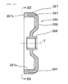
- FIGs. 11 and 12 each showing a clutch outer 382 of Embodiment 4 of the present invention alone, explanation will be provided for features of a centrifugal shoe clutch structure of Embodiment 4.
- the clutch outer 382 of Embodiment 4 is different from the clutch outer 82 of Embodiment 1.
- the rest of Embodiment 4 is virtually the same as that of Embodiment 1.
- Figs. 1 to 3 will be referred to.
- Duplicated illustrations and explanations will be omitted.
- components of Embodiment 4 which are the same as those of Embodiment 1 are denoted by the same reference numerals. Thereby, explanation of such components will be omitted.
- each of components of Embodiment 4 which corresponds to those of Embodiment 1 but will be explained discriminatingly is denoted by a reference numeral of three hundred and something whose last two digits are equal to the reference numeral of the corresponding component of Embodiment 1; each of components of Embodiment 4 which is completely different from those of Embodiment 1 is denoted by any other reference numeral of three hundred and something; and explanation will be provided mainly for what makes components of Embodiment 4 different from those of Embodiment 1.
- An axis of the clutch outer 382 of Embodiment 4 virtually coincides with the axis Z of the transmission output shaft 45 as in the case of Embodiment 1.
- a boss portion 386, a drum portion 387 and a connecting wall portion 388 are integrally cast by use of the same cast iron material by casting as in the case of Embodiment 1.
- the thickness td of the drum portion 387 is made thicker than any one of the thicknesses tw1, tw2, tw3 of the connecting wall portion 188 (see Fig. 4 ) as in the case of the clutch outer which has been explained with regard to Embodiment 1.
- An inner peripheral surface of the drum portion 387 forms a cylinder-shaped friction surface 387a.
- the drum portion 387 is provided with natural frequency adjusting holes 397 at equal intervals in a circumferential direction of the drum portion 387.
- the natural frequency adjusting holes 397 extend in an axial (center axial) Z direction of the clutch outer 382. Furthermore, the natural frequency adjusting holes 397 are provided in a portion of the drum portion 387, which continues to the connecting wall portion 388, in order that an end surface portion 387b of the drum portion 387 should not be opened.
- Figs. 11 and 12 show the natural frequency adjusting holes 397 as holes whose cross sections are round, the natural frequency adjusting holes 397 may be holes whose cross sections are oval.
- the illustration of the balance holes 93 is omitted from Figs. 11 and 12 , the balance holes 93 are processed as in the case of Embodiment 1. The positions of the balance holes 93 and the number of balance holes 93 are determined depending on the necessity.
- the foregoing centrifugal shoe clutch structure of Embodiment 4 brings about the same operations/workings-effects as does the centrifugal shoe clutch structure of Embodiment 1, and additionally brings about the following operations/workings-effects.
- the natural frequency of the clutch outer 382 was set up preferably by use of the natural frequency adjusting holes 397, the clutch squeak resulting from the resonance with the frequency which occurred due to the sliding movement on the clutch shoes 84 during the clutch connection was prevented.
- the end surface portion 387b of the drum portion 387 was closed, stress was inhibited from increasing in the end surface portion 387b, and the clutch squeak was prevented.
- Figs. 13 to 16 each showing a clutch outer 482 of Embodiment 5 of the present invention alone, explanation will be provided for features of a centrifugal shoe clutch structure of Embodiment 5.
- the clutch outer 482 of Embodiment 5 is different from the clutch outer 82 of Embodiment 1.
- the rest of Embodiment 5 is virtually the same as that of Embodiment 1.
- Figs. 1 to 3 will be referred to.
- Duplicated illustrations and explanations will be omitted.
- components of Embodiment 5 which are the same as those of Embodiment 1 are denoted by the same reference numerals. Thereby, explanation of such components will be omitted.
- each of components of Embodiment 5 which corresponds to those of Embodiment 1 but will be explained discriminatingly is denoted by a reference numeral of four hundred and something whose last two digits are equal to the reference numeral of the corresponding component of Embodiment 1; each of components of Embodiment 5 which is completely different from those of Embodiment 1 is denoted by any other reference numeral of four hundred and something; and explanation will be provided mainly for what makes components of Embodiment 5 different from those of Embodiment 1.
- An axis of the clutch outer 482 of Embodiment 5 virtually coincides with the axis Z of the transmission output shaft 45 as in the case of Embodiment 1.
- a boss portion 486, a drum portion 487 and a connecting wall portion 488 are integrally cast by use of the same cast iron material by casting as in the case of Embodiment 1.
- the thickness td of the drum portion 487 is made thicker than any one of the thicknesses tw1, tw2, tw3 of the connecting wall portion 388 (see Fig. 4 ) as in the case of the clutch outer which has been explained with regard to Embodiment 1.
- An inner peripheral surface of the drum portion 487 forms a cylinder-shaped friction surface 487a.
- the drum portion 487 is provided with natural frequency adjusting holes 497A which extend in an axial (center axial) Z direction of the clutch outer 482.
- the natural frequency adjusting holes 497A are holes whose cross sections are round.
- the natural frequency adjusting holes 497A are provided in a portion of the drum portion 487, which continues to the connecting wall portion 488, in order that an end surface portion 487b of the drum portion 487 should not be opened.
- the natural frequency adjusting holes 497A are provided in a way that the phases of the respective natural frequency adjusting holes 497A are unequal in the circumferential direction of the drum portion 487.
- the natural frequency adjusting holes 497A are provided with a pitch of 45° in the right upper quarter and the left lower quarter, and with a pitch of 30° in the left upper quarter and the right lower quarter.
- the natural frequency adjusting holes 497A are placed point-symmetrically with the axis Z of the clutch outer 482, but at unequal intervals in the circumferential direction of the clutch outer 482.
- Figs. 15 and 16 What is shown in Figs. 15 and 16 is a modification of Embodiment 5.
- this modification instead of the natural frequency adjusting holes 497A whose cross sections are round, natural frequency adjusting holes 497B whose cross sections are oval are provided to the drum portion 487 in the axial (center axial) Z direction of the clutch outer 482. The rest of the modification is the same as that of Embodiment 5.
- the natural frequency adjusting holes 497B are provided in the portion of the drum portion 487, which continues to the connecting wall portion 488, in order that the end surface portion 487b of the drum portion 487 should not be opened.
- the natural frequency adjusting holes 497B are provided in a way that the phases of the respective natural frequency adjusting holes 497B are unequal in the circumferential direction of the drum portion 487.
- the natural frequency adjusting holes 497B are provided with a pitch of 45° in the right upper quarter and the left lower quarter, and with a pitch of 30° in the left upper quarter and the right lower quarter.
- the natural frequency adjusting holes 497B are placed point-symmetrically with the axis Z of the clutch outer 482, but at unequal intervals in the circumferential direction of the clutch outer 482.
- the balance holes 93 are processed as in the case of Embodiment 1. The positions of the balance holes 93 and the number of balance holes 93 are determined depending on the necessity.
- the foregoing centrifugal shoe clutch structure of Embodiment 5 brings about the same operations/workings-effects as does the centrifugal shoe clutch structure of Embodiment 1, and additionally brings about the following operations/workings-effects.
- the natural frequency of the clutch outer 482 was set up preferably by use of the natural frequency adjusting holes 497A or the natural frequency adjusting holes 497B, the clutch squeak resulting from the resonance with the frequency which occurred due to the sliding movement on the clutch shoes 84 during the clutch connection was prevented.
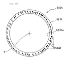
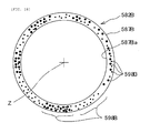
- the cast iron material of the clutch outer 582A or the clutch outer 582B is a spheroidal graphite cast iron.
- the clutch outer 582A or the clutch outer 582B is formed in a way that a spheroidal graphite 598A or a spheroidal graphite 598B contained therein is distributed unevenly in the circumferential direction of a drum portion 587A or a drum portion 587B.
- Embodiment 6 The rest of Embodiment 6 is the same as that of each of Embodiment 1 to Embodiment 5. For this reason, the drawings related to each embodiment will be referred to. Duplicated illustrations and explanations will be omitted. Furthermore, components of Example 6 which are the same as those of the other embodiments are denoted by the same reference numerals. Thereby, explanation of such components will be omitted.
- each of components of Example 6 which corresponds to those of the other embodiments but will be explained discriminatingly is denoted by a reference numeral of five hundred and something whose last two digits are equal to the reference numeral of the corresponding component of the other embodiments; each of components of Example 6 which is completely different from those of the other embodiments is denoted by any other reference numeral of five hundred and something; and explanation will be provided mainly for what makes components of Example 6 different from those of the other embodiments.
- Fig. 17 schematically shows a front cross section of the drum portion 587A of the clutch outer 582A of Embodiment 6.
- the state of distribution of the spheroidal graphite 598A contained in the spheroidal graphite cast iron as the cast iron material of the drum portion 587A is schematically shown in the cross section. It is a matter of course that the cross-sectional dimension of the drum portion 587A and the cross-sectional dimension of the spheroidal graphite 598A are too different in range to be illustrated simultaneously. For this reason, Fig. 17 only shows an image of the distribution of the spheroidal graphite 598A in the circumferential direction of the drum portion 587A.
- the clutch outer 582A is formed in a way that the spheroidal graphite 598A contained therein is unevenly distributed in the circumferential direction of the drum portion 587A.
- Fig. 18 schematically shows a front cross section of the drum portion 587B of the clutch outer 582B of Embodiment 6.
- the state of distribution of the spheroidal graphite 598B contained in the spheroidal graphite cast iron as the cast iron material of the drum portion 587B is schematically shown in the cross section. It is a matter of course that the cross-sectional dimension of the drum portion 587B and the cross-sectional dimension of the spheroidal graphite 598B are too different in range to be illustrated simultaneously. For this reason, Fig. 18 only shows an image of the distribution of the spheroidal graphite 598B in the circumferential direction of the drum portion 587B.
- the clutch outer 582B is formed in a way that the spheroidal graphite 598B contained therein is unevenly distributed in the circumferential direction of the drum portion 587B.
- Embodiment 6 is that which is obtained by adding the configuration of the clutch outer 582A or the clutch outer 582B of Embodiment 6 to the configurations of the clutch outers 82, 182, 282, 382, 482 of Embodiments 1 to 5.
- Embodiment 6 brings about the same operations/workings-effects as does the centrifugal shoe clutch structure of any one of Embodiments 1 to 5, and additionally brings about the following operations/workings-effects. Because the spheroidal graphite cast iron was used as the cast iron material, the strength of the clutch outer 582A or the clutch outer 582B was increased.
- the lubrication action of the spheroidal graphite 598A or the spheroidal graphite 598B which was the internal component of the clutch outer 582A or the clutch outer 582B made of the spheroidal graphite cast iron, stabilized the characteristics of the sliding of the clutch shoes 84 on the cylinder-shaped friction surface 587Aa or the cylinder-shaped friction surface 587Ba.
- the lubrication action of the spheroidal graphite 598A or the spheroidal graphite 598B thus made it easy to control the frequency which occurred due to the sliding movement thereon, as well as accordingly made it easy to make a setup for avoidance of the resonance with the natural frequency of the clutch outer 582A or the clutch outer 582B. Furthermore, the vibration damping effect resulting from the change in the density of the spheroidal graphite 598A or the spheroidal graphite 598B depending on the locations enhanced the effect of preventing the clutch squeak.
- the cylinder-shaped friction surface 578Aa of the drum portion 587A or the cylinder-shaped friction surface 578Ba of the drum portion 587B is shaped like a cylinder by machining.
- the clutch outers 82, 182, 282, 382 482 of Embodiments 1 to 5 additionally having such a constitution are cast by use of the spheroidal graphite cast iron.
- the cylinder-shaped friction surfaces 87a, 187a, 287a, 387a, 487a of the respective drum portions 87, 187, 287, 387, 487 are shaped like a cylinder by machining.
- the spheroidal graphite 598A or the spheroidal graphite 598B is exposed in the cylinder-shaped friction surfaces 87a, 187a, 287a, 387a, 487a, 578Aa, 578Ba by machining. Accordingly, the characteristic of preventing the clutch squeak can be kept high from the beginning of the use of the clutch.
- the present invention may be applied to vehicles whose internal combustion engine has a different mode or a different number of cylinders. Moreover, it goes without saying that the present invention may be applied to power units other than vehicle-mounted power units, too, as long as the power units include a similar centrifugal shoe clutch. Furthermore, the type, placement order and orientation of the transmission system in front of the centrifugal shoe clutch, as well as the direction of the end surface of the drum portion of the clutch outer with respect to the clutch inner, are not limited to those of the foregoing embodiments.
Landscapes
- Engineering & Computer Science (AREA)
- General Engineering & Computer Science (AREA)
- Mechanical Engineering (AREA)
- One-Way And Automatic Clutches, And Combinations Of Different Clutches (AREA)
Applications Claiming Priority (1)
| Application Number | Priority Date | Filing Date | Title |
|---|---|---|---|
| JP2010103277A JP5503397B2 (ja) | 2010-04-28 | 2010-04-28 | 遠心シュー式クラッチ構造 |
Publications (3)
| Publication Number | Publication Date |
|---|---|
| EP2383484A2 true EP2383484A2 (de) | 2011-11-02 |
| EP2383484A3 EP2383484A3 (de) | 2012-01-25 |
| EP2383484B1 EP2383484B1 (de) | 2013-06-05 |
Family
ID=44281065
Family Applications (1)
| Application Number | Title | Priority Date | Filing Date |
|---|---|---|---|
| EP11163120.6A Not-in-force EP2383484B1 (de) | 2010-04-28 | 2011-04-20 | Zentrifugale Schuh-Kupplungsstruktur |
Country Status (3)
| Country | Link |
|---|---|
| EP (1) | EP2383484B1 (de) |
| JP (1) | JP5503397B2 (de) |
| CN (1) | CN102235448B (de) |
Cited By (1)
| Publication number | Priority date | Publication date | Assignee | Title |
|---|---|---|---|---|
| US20130020170A1 (en) * | 2010-01-27 | 2013-01-24 | Kabushiki Kaisha F.C.C | Centrifugal clutch apparatus |
Families Citing this family (1)
| Publication number | Priority date | Publication date | Assignee | Title |
|---|---|---|---|---|
| JP7045127B2 (ja) * | 2018-05-18 | 2022-03-31 | 株式会社エフ・シー・シー | 遠心クラッチ |
Citations (1)
| Publication number | Priority date | Publication date | Assignee | Title |
|---|---|---|---|---|
| JP2005233232A (ja) | 2004-02-17 | 2005-09-02 | Honda Motor Co Ltd | 遠心クラッチ |
Family Cites Families (13)
| Publication number | Priority date | Publication date | Assignee | Title |
|---|---|---|---|---|
| GB496800A (en) * | 1937-05-11 | 1938-12-06 | Bosch Gmbh Robert | Improvements in or relating to centrifugal clutches |
| FR1172593A (fr) * | 1957-02-09 | 1959-02-12 | Bernard Moteurs | Perfectionnements apportés aux dispositifs du genre des embrayages centrifuges |
| GB933615A (en) * | 1961-03-03 | 1963-08-08 | Sintered Products Ltd | Improvements in or relating to torque transmitting clutches |
| DE2009607B2 (de) * | 1970-03-02 | 1972-01-27 | Kirschey, Gerhard, Dipl Ing , 5600 Wuppertal Vohwinkel | Fliehkraftkupplung |
| US4294342A (en) * | 1978-07-28 | 1981-10-13 | Dyneer Corporation | Centrifugal clutch construction |
| JPS571939U (de) * | 1980-06-04 | 1982-01-07 | ||
| JPH0643502B2 (ja) * | 1988-09-29 | 1994-06-08 | アイシン化工株式会社 | 摩擦材 |
| JPH02138437A (ja) * | 1988-11-16 | 1990-05-28 | Hitachi Metals Ltd | ハブドラム |
| JPH07119764A (ja) * | 1993-10-28 | 1995-05-09 | Aisin Chem Co Ltd | 遠心クラッチ用クラッチドラム |
| JP3322015B2 (ja) * | 1994-08-26 | 2002-09-09 | スズキ株式会社 | 摩擦係合装置のハウジング制振構造 |
| JP3304733B2 (ja) * | 1995-04-25 | 2002-07-22 | 日産自動車株式会社 | 制動装置用回転放熱板及びドラム式ブレーキ |
| JP4043272B2 (ja) * | 2002-04-10 | 2008-02-06 | 株式会社キリウ | 車両用ブレーキ装置における回転制動部材の防錆処理方法 |
| JP2007198516A (ja) * | 2006-01-27 | 2007-08-09 | Honda Motor Co Ltd | 遠心クラッチ |
-
2010
- 2010-04-28 JP JP2010103277A patent/JP5503397B2/ja not_active Expired - Fee Related
-
2011
- 2011-04-20 EP EP11163120.6A patent/EP2383484B1/de not_active Not-in-force
- 2011-04-22 CN CN2011101070718A patent/CN102235448B/zh not_active Expired - Fee Related
Patent Citations (1)
| Publication number | Priority date | Publication date | Assignee | Title |
|---|---|---|---|---|
| JP2005233232A (ja) | 2004-02-17 | 2005-09-02 | Honda Motor Co Ltd | 遠心クラッチ |
Cited By (2)
| Publication number | Priority date | Publication date | Assignee | Title |
|---|---|---|---|---|
| US20130020170A1 (en) * | 2010-01-27 | 2013-01-24 | Kabushiki Kaisha F.C.C | Centrifugal clutch apparatus |
| US9611904B2 (en) * | 2010-01-27 | 2017-04-04 | Kabushiki Kaisha F.C.C. | Centrifugal clutch apparatus |
Also Published As
| Publication number | Publication date |
|---|---|
| JP2011231870A (ja) | 2011-11-17 |
| CN102235448B (zh) | 2013-08-14 |
| CN102235448A (zh) | 2011-11-09 |
| JP5503397B2 (ja) | 2014-05-28 |
| EP2383484A3 (de) | 2012-01-25 |
| EP2383484B1 (de) | 2013-06-05 |
Similar Documents
| Publication | Publication Date | Title |
|---|---|---|
| JP4364668B2 (ja) | 遠心クラッチ | |
| CA2461867C (en) | Power transmission system of engine | |
| US7857721B2 (en) | Belt-type continuously variable transmission and straddle-type vehicle | |
| US20080015067A1 (en) | Belt-Type Continuously Variable Transmission and Straddle-Type Vehicle | |
| WO2012017784A1 (ja) | 内燃機関のクランクシャフトの支持構造 | |
| EP2110532B1 (de) | Motor und Fahrzeug damit | |
| EP2383484B1 (de) | Zentrifugale Schuh-Kupplungsstruktur | |
| US20090000589A1 (en) | Recreational vehicle engine design | |
| EP1201535A2 (de) | Fahrzeuggetriebe | |
| CN212536472U (zh) | 一种用于自动变速箱的液力冷却离合器 | |
| EP2314896B1 (de) | Stufenloses Getriebe und Grätschsitzfahrzeug | |
| JP2008185056A (ja) | ベルト式無段変速装置、それを備えた鞍乗型車両及びベルト式無段変速装置の押圧体 | |
| JP2012141044A (ja) | クランク軸支持構造 | |
| JP7598990B1 (ja) | 遠心クラッチ、および車両 | |
| JP2002147553A (ja) | 車両用ベルト式変速装置 | |
| JP4206331B2 (ja) | 4サイクルエンジン用クランク軸 | |
| JP2001082248A (ja) | エンジン | |
| JP2008180237A (ja) | クランクシャフトの支持構造 | |
| CN1276490A (zh) | 曲轴的支承构造 | |
| TW200538656A (en) | Driven pulley device of V-belt type automatic transmission | |
| CN119531985A (zh) | 发动机的配气凸轮轴、发动机以及车辆 | |
| JP5681603B2 (ja) | クランクシャフト支持構造 | |
| JP5971519B2 (ja) | 車両用エンジンのフライホイール | |
| JP2002147581A (ja) | 車両用ベルト式変速装置 | |
| JP2023050403A (ja) | 内燃機関の防振装置 |
Legal Events
| Date | Code | Title | Description |
|---|---|---|---|
| 17P | Request for examination filed |
Effective date: 20110420 |
|
| AK | Designated contracting states |
Kind code of ref document: A2 Designated state(s): AL AT BE BG CH CY CZ DE DK EE ES FI FR GB GR HR HU IE IS IT LI LT LU LV MC MK MT NL NO PL PT RO RS SE SI SK SM TR |
|
| AX | Request for extension of the european patent |
Extension state: BA ME |
|
| PUAI | Public reference made under article 153(3) epc to a published international application that has entered the european phase |
Free format text: ORIGINAL CODE: 0009012 |
|
| PUAL | Search report despatched |
Free format text: ORIGINAL CODE: 0009013 |
|
| AK | Designated contracting states |
Kind code of ref document: A3 Designated state(s): AL AT BE BG CH CY CZ DE DK EE ES FI FR GB GR HR HU IE IS IT LI LT LU LV MC MK MT NL NO PL PT RO RS SE SI SK SM TR |
|
| AX | Request for extension of the european patent |
Extension state: BA ME |
|
| RIC1 | Information provided on ipc code assigned before grant |
Ipc: F16D 43/18 20060101AFI20111216BHEP |
|
| GRAP | Despatch of communication of intention to grant a patent |
Free format text: ORIGINAL CODE: EPIDOSNIGR1 |
|
| RIN1 | Information on inventor provided before grant (corrected) |
Inventor name: MAEKAWA, KEIICHI C/O HONDA R&D CO., LTD. Inventor name: KOMURO, HIROKAZU C/O HONDA R&D CO., LTD. Inventor name: HONGO, TAKAHARU C/O HONDA R&D CO., LTD. Inventor name: NARITA, MASAAKI C/O HONDA R&D CO., LTD. Inventor name: IMAMURA, TETSUYA C/O HONDA R&D CO., LTD. Inventor name: NUKADA, YOSHITAKA C/O HONDA R&D CO., LTD. Inventor name: MATSUURA, KOHEI C/O HONDA R&D CO., LTD. |
|
| GRAS | Grant fee paid |
Free format text: ORIGINAL CODE: EPIDOSNIGR3 |
|
| GRAA | (expected) grant |
Free format text: ORIGINAL CODE: 0009210 |
|
| AK | Designated contracting states |
Kind code of ref document: B1 Designated state(s): AL AT BE BG CH CY CZ DE DK EE ES FI FR GB GR HR HU IE IS IT LI LT LU LV MC MK MT NL NO PL PT RO RS SE SI SK SM TR |
|
| REG | Reference to a national code |
Ref country code: GB Ref legal event code: FG4D |
|
| REG | Reference to a national code |
Ref country code: CH Ref legal event code: EP |
|
| REG | Reference to a national code |
Ref country code: AT Ref legal event code: REF Ref document number: 615840 Country of ref document: AT Kind code of ref document: T Effective date: 20130615 |
|
| REG | Reference to a national code |
Ref country code: IE Ref legal event code: FG4D |
|
| REG | Reference to a national code |
Ref country code: DE Ref legal event code: R096 Ref document number: 602011001896 Country of ref document: DE Effective date: 20130725 |
|
| REG | Reference to a national code |
Ref country code: AT Ref legal event code: MK05 Ref document number: 615840 Country of ref document: AT Kind code of ref document: T Effective date: 20130605 |
|
| PG25 | Lapsed in a contracting state [announced via postgrant information from national office to epo] |
Ref country code: FI Free format text: LAPSE BECAUSE OF FAILURE TO SUBMIT A TRANSLATION OF THE DESCRIPTION OR TO PAY THE FEE WITHIN THE PRESCRIBED TIME-LIMIT Effective date: 20130605 Ref country code: NO Free format text: LAPSE BECAUSE OF FAILURE TO SUBMIT A TRANSLATION OF THE DESCRIPTION OR TO PAY THE FEE WITHIN THE PRESCRIBED TIME-LIMIT Effective date: 20130905 Ref country code: SI Free format text: LAPSE BECAUSE OF FAILURE TO SUBMIT A TRANSLATION OF THE DESCRIPTION OR TO PAY THE FEE WITHIN THE PRESCRIBED TIME-LIMIT Effective date: 20130605 Ref country code: LT Free format text: LAPSE BECAUSE OF FAILURE TO SUBMIT A TRANSLATION OF THE DESCRIPTION OR TO PAY THE FEE WITHIN THE PRESCRIBED TIME-LIMIT Effective date: 20130605 Ref country code: ES Free format text: LAPSE BECAUSE OF FAILURE TO SUBMIT A TRANSLATION OF THE DESCRIPTION OR TO PAY THE FEE WITHIN THE PRESCRIBED TIME-LIMIT Effective date: 20130916 Ref country code: GR Free format text: LAPSE BECAUSE OF FAILURE TO SUBMIT A TRANSLATION OF THE DESCRIPTION OR TO PAY THE FEE WITHIN THE PRESCRIBED TIME-LIMIT Effective date: 20130906 Ref country code: SE Free format text: LAPSE BECAUSE OF FAILURE TO SUBMIT A TRANSLATION OF THE DESCRIPTION OR TO PAY THE FEE WITHIN THE PRESCRIBED TIME-LIMIT Effective date: 20130605 Ref country code: AT Free format text: LAPSE BECAUSE OF FAILURE TO SUBMIT A TRANSLATION OF THE DESCRIPTION OR TO PAY THE FEE WITHIN THE PRESCRIBED TIME-LIMIT Effective date: 20130605 |
|
| REG | Reference to a national code |
Ref country code: NL Ref legal event code: VDEP Effective date: 20130605 |
|
| REG | Reference to a national code |
Ref country code: LT Ref legal event code: MG4D |
|
| PG25 | Lapsed in a contracting state [announced via postgrant information from national office to epo] |
Ref country code: RS Free format text: LAPSE BECAUSE OF FAILURE TO SUBMIT A TRANSLATION OF THE DESCRIPTION OR TO PAY THE FEE WITHIN THE PRESCRIBED TIME-LIMIT Effective date: 20130605 Ref country code: BG Free format text: LAPSE BECAUSE OF FAILURE TO SUBMIT A TRANSLATION OF THE DESCRIPTION OR TO PAY THE FEE WITHIN THE PRESCRIBED TIME-LIMIT Effective date: 20130905 Ref country code: HR Free format text: LAPSE BECAUSE OF FAILURE TO SUBMIT A TRANSLATION OF THE DESCRIPTION OR TO PAY THE FEE WITHIN THE PRESCRIBED TIME-LIMIT Effective date: 20130605 |
|
| PG25 | Lapsed in a contracting state [announced via postgrant information from national office to epo] |
Ref country code: LV Free format text: LAPSE BECAUSE OF FAILURE TO SUBMIT A TRANSLATION OF THE DESCRIPTION OR TO PAY THE FEE WITHIN THE PRESCRIBED TIME-LIMIT Effective date: 20130605 |
|
| PG25 | Lapsed in a contracting state [announced via postgrant information from national office to epo] |
Ref country code: BE Free format text: LAPSE BECAUSE OF FAILURE TO SUBMIT A TRANSLATION OF THE DESCRIPTION OR TO PAY THE FEE WITHIN THE PRESCRIBED TIME-LIMIT Effective date: 20130605 Ref country code: EE Free format text: LAPSE BECAUSE OF FAILURE TO SUBMIT A TRANSLATION OF THE DESCRIPTION OR TO PAY THE FEE WITHIN THE PRESCRIBED TIME-LIMIT Effective date: 20130605 Ref country code: IS Free format text: LAPSE BECAUSE OF FAILURE TO SUBMIT A TRANSLATION OF THE DESCRIPTION OR TO PAY THE FEE WITHIN THE PRESCRIBED TIME-LIMIT Effective date: 20131005 Ref country code: CZ Free format text: LAPSE BECAUSE OF FAILURE TO SUBMIT A TRANSLATION OF THE DESCRIPTION OR TO PAY THE FEE WITHIN THE PRESCRIBED TIME-LIMIT Effective date: 20130605 Ref country code: PT Free format text: LAPSE BECAUSE OF FAILURE TO SUBMIT A TRANSLATION OF THE DESCRIPTION OR TO PAY THE FEE WITHIN THE PRESCRIBED TIME-LIMIT Effective date: 20131007 Ref country code: SK Free format text: LAPSE BECAUSE OF FAILURE TO SUBMIT A TRANSLATION OF THE DESCRIPTION OR TO PAY THE FEE WITHIN THE PRESCRIBED TIME-LIMIT Effective date: 20130605 |
|
| PG25 | Lapsed in a contracting state [announced via postgrant information from national office to epo] |
Ref country code: NL Free format text: LAPSE BECAUSE OF FAILURE TO SUBMIT A TRANSLATION OF THE DESCRIPTION OR TO PAY THE FEE WITHIN THE PRESCRIBED TIME-LIMIT Effective date: 20130605 Ref country code: PL Free format text: LAPSE BECAUSE OF FAILURE TO SUBMIT A TRANSLATION OF THE DESCRIPTION OR TO PAY THE FEE WITHIN THE PRESCRIBED TIME-LIMIT Effective date: 20130605 Ref country code: RO Free format text: LAPSE BECAUSE OF FAILURE TO SUBMIT A TRANSLATION OF THE DESCRIPTION OR TO PAY THE FEE WITHIN THE PRESCRIBED TIME-LIMIT Effective date: 20130605 |
|
| PLBE | No opposition filed within time limit |
Free format text: ORIGINAL CODE: 0009261 |
|
| STAA | Information on the status of an ep patent application or granted ep patent |
Free format text: STATUS: NO OPPOSITION FILED WITHIN TIME LIMIT |
|
| PG25 | Lapsed in a contracting state [announced via postgrant information from national office to epo] |
Ref country code: DK Free format text: LAPSE BECAUSE OF FAILURE TO SUBMIT A TRANSLATION OF THE DESCRIPTION OR TO PAY THE FEE WITHIN THE PRESCRIBED TIME-LIMIT Effective date: 20130605 |
|
| 26N | No opposition filed |
Effective date: 20140306 |
|
| REG | Reference to a national code |
Ref country code: DE Ref legal event code: R097 Ref document number: 602011001896 Country of ref document: DE Effective date: 20140306 |
|
| PG25 | Lapsed in a contracting state [announced via postgrant information from national office to epo] |
Ref country code: LU Free format text: LAPSE BECAUSE OF FAILURE TO SUBMIT A TRANSLATION OF THE DESCRIPTION OR TO PAY THE FEE WITHIN THE PRESCRIBED TIME-LIMIT Effective date: 20140420 Ref country code: MC Free format text: LAPSE BECAUSE OF FAILURE TO SUBMIT A TRANSLATION OF THE DESCRIPTION OR TO PAY THE FEE WITHIN THE PRESCRIBED TIME-LIMIT Effective date: 20130605 |
|
| REG | Reference to a national code |
Ref country code: CH Ref legal event code: PL |
|
| REG | Reference to a national code |
Ref country code: IE Ref legal event code: MM4A |
|
| PG25 | Lapsed in a contracting state [announced via postgrant information from national office to epo] |
Ref country code: LI Free format text: LAPSE BECAUSE OF NON-PAYMENT OF DUE FEES Effective date: 20140430 Ref country code: CH Free format text: LAPSE BECAUSE OF NON-PAYMENT OF DUE FEES Effective date: 20140430 |
|
| PG25 | Lapsed in a contracting state [announced via postgrant information from national office to epo] |
Ref country code: IE Free format text: LAPSE BECAUSE OF NON-PAYMENT OF DUE FEES Effective date: 20140420 |
|
| GBPC | Gb: european patent ceased through non-payment of renewal fee |
Effective date: 20150420 |
|
| PG25 | Lapsed in a contracting state [announced via postgrant information from national office to epo] |
Ref country code: GB Free format text: LAPSE BECAUSE OF NON-PAYMENT OF DUE FEES Effective date: 20150420 |
|
| REG | Reference to a national code |
Ref country code: FR Ref legal event code: PLFP Year of fee payment: 6 |
|
| PG25 | Lapsed in a contracting state [announced via postgrant information from national office to epo] |
Ref country code: MT Free format text: LAPSE BECAUSE OF FAILURE TO SUBMIT A TRANSLATION OF THE DESCRIPTION OR TO PAY THE FEE WITHIN THE PRESCRIBED TIME-LIMIT Effective date: 20130605 |
|
| PG25 | Lapsed in a contracting state [announced via postgrant information from national office to epo] |
Ref country code: SM Free format text: LAPSE BECAUSE OF FAILURE TO SUBMIT A TRANSLATION OF THE DESCRIPTION OR TO PAY THE FEE WITHIN THE PRESCRIBED TIME-LIMIT Effective date: 20130605 |
|
| PG25 | Lapsed in a contracting state [announced via postgrant information from national office to epo] |
Ref country code: CY Free format text: LAPSE BECAUSE OF FAILURE TO SUBMIT A TRANSLATION OF THE DESCRIPTION OR TO PAY THE FEE WITHIN THE PRESCRIBED TIME-LIMIT Effective date: 20130605 |
|
| PG25 | Lapsed in a contracting state [announced via postgrant information from national office to epo] |
Ref country code: HU Free format text: LAPSE BECAUSE OF FAILURE TO SUBMIT A TRANSLATION OF THE DESCRIPTION OR TO PAY THE FEE WITHIN THE PRESCRIBED TIME-LIMIT; INVALID AB INITIO Effective date: 20110420 Ref country code: TR Free format text: LAPSE BECAUSE OF FAILURE TO SUBMIT A TRANSLATION OF THE DESCRIPTION OR TO PAY THE FEE WITHIN THE PRESCRIBED TIME-LIMIT Effective date: 20130605 |
|
| REG | Reference to a national code |
Ref country code: FR Ref legal event code: PLFP Year of fee payment: 7 |
|
| REG | Reference to a national code |
Ref country code: FR Ref legal event code: PLFP Year of fee payment: 8 |
|
| PGFP | Annual fee paid to national office [announced via postgrant information from national office to epo] |
Ref country code: FR Payment date: 20180315 Year of fee payment: 8 |
|
| PG25 | Lapsed in a contracting state [announced via postgrant information from national office to epo] |
Ref country code: MK Free format text: LAPSE BECAUSE OF FAILURE TO SUBMIT A TRANSLATION OF THE DESCRIPTION OR TO PAY THE FEE WITHIN THE PRESCRIBED TIME-LIMIT Effective date: 20130605 |
|
| PG25 | Lapsed in a contracting state [announced via postgrant information from national office to epo] |
Ref country code: AL Free format text: LAPSE BECAUSE OF FAILURE TO SUBMIT A TRANSLATION OF THE DESCRIPTION OR TO PAY THE FEE WITHIN THE PRESCRIBED TIME-LIMIT Effective date: 20130605 |
|
| PGFP | Annual fee paid to national office [announced via postgrant information from national office to epo] |
Ref country code: DE Payment date: 20190410 Year of fee payment: 9 Ref country code: IT Payment date: 20190419 Year of fee payment: 9 |
|
| REG | Reference to a national code |
Ref country code: DE Ref legal event code: R084 Ref document number: 602011001896 Country of ref document: DE |
|
| PG25 | Lapsed in a contracting state [announced via postgrant information from national office to epo] |
Ref country code: FR Free format text: LAPSE BECAUSE OF NON-PAYMENT OF DUE FEES Effective date: 20190430 |
|
| REG | Reference to a national code |
Ref country code: DE Ref legal event code: R119 Ref document number: 602011001896 Country of ref document: DE |
|
| PG25 | Lapsed in a contracting state [announced via postgrant information from national office to epo] |
Ref country code: DE Free format text: LAPSE BECAUSE OF NON-PAYMENT OF DUE FEES Effective date: 20201103 |
|
| PG25 | Lapsed in a contracting state [announced via postgrant information from national office to epo] |
Ref country code: IT Free format text: LAPSE BECAUSE OF NON-PAYMENT OF DUE FEES Effective date: 20200420 |