EP2379949B1 - Cooling device - Google Patents
Cooling device Download PDFInfo
- Publication number
- EP2379949B1 EP2379949B1 EP10701571.1A EP10701571A EP2379949B1 EP 2379949 B1 EP2379949 B1 EP 2379949B1 EP 10701571 A EP10701571 A EP 10701571A EP 2379949 B1 EP2379949 B1 EP 2379949B1
- Authority
- EP
- European Patent Office
- Prior art keywords
- air
- wall
- instance
- cooling
- water
- Prior art date
- Legal status (The legal status is an assumption and is not a legal conclusion. Google has not performed a legal analysis and makes no representation as to the accuracy of the status listed.)
- Active
Links
Images


Classifications
-
- F—MECHANICAL ENGINEERING; LIGHTING; HEATING; WEAPONS; BLASTING
- F24—HEATING; RANGES; VENTILATING
- F24F—AIR-CONDITIONING; AIR-HUMIDIFICATION; VENTILATION; USE OF AIR CURRENTS FOR SCREENING
- F24F5/00—Air-conditioning systems or apparatus not covered by F24F1/00 or F24F3/00, e.g. using solar heat or combined with household units such as an oven or water heater
- F24F5/0007—Air-conditioning systems or apparatus not covered by F24F1/00 or F24F3/00, e.g. using solar heat or combined with household units such as an oven or water heater cooling apparatus specially adapted for use in air-conditioning
- F24F5/0035—Air-conditioning systems or apparatus not covered by F24F1/00 or F24F3/00, e.g. using solar heat or combined with household units such as an oven or water heater cooling apparatus specially adapted for use in air-conditioning using evaporation
-
- B—PERFORMING OPERATIONS; TRANSPORTING
- B60—VEHICLES IN GENERAL
- B60H—ARRANGEMENTS OF HEATING, COOLING, VENTILATING OR OTHER AIR-TREATING DEVICES SPECIALLY ADAPTED FOR PASSENGER OR GOODS SPACES OF VEHICLES
- B60H1/00—Heating, cooling or ventilating [HVAC] devices
- B60H1/32—Cooling devices
- B60H1/3202—Cooling devices using evaporation, i.e. not including a compressor, e.g. involving fuel or water evaporation
-
- F—MECHANICAL ENGINEERING; LIGHTING; HEATING; WEAPONS; BLASTING
- F24—HEATING; RANGES; VENTILATING
- F24F—AIR-CONDITIONING; AIR-HUMIDIFICATION; VENTILATION; USE OF AIR CURRENTS FOR SCREENING
- F24F5/00—Air-conditioning systems or apparatus not covered by F24F1/00 or F24F3/00, e.g. using solar heat or combined with household units such as an oven or water heater
- F24F5/0089—Systems using radiation from walls or panels
- F24F5/0092—Systems using radiation from walls or panels ceilings, e.g. cool ceilings
-
- B—PERFORMING OPERATIONS; TRANSPORTING
- B60—VEHICLES IN GENERAL
- B60H—ARRANGEMENTS OF HEATING, COOLING, VENTILATING OR OTHER AIR-TREATING DEVICES SPECIALLY ADAPTED FOR PASSENGER OR GOODS SPACES OF VEHICLES
- B60H1/00—Heating, cooling or ventilating [HVAC] devices
- B60H1/00007—Combined heating, ventilating, or cooling devices
- B60H1/00207—Combined heating, ventilating, or cooling devices characterised by the position of the HVAC devices with respect to the passenger compartment
- B60H2001/00235—Devices in the roof area of the passenger compartment
-
- Y—GENERAL TAGGING OF NEW TECHNOLOGICAL DEVELOPMENTS; GENERAL TAGGING OF CROSS-SECTIONAL TECHNOLOGIES SPANNING OVER SEVERAL SECTIONS OF THE IPC; TECHNICAL SUBJECTS COVERED BY FORMER USPC CROSS-REFERENCE ART COLLECTIONS [XRACs] AND DIGESTS
- Y02—TECHNOLOGIES OR APPLICATIONS FOR MITIGATION OR ADAPTATION AGAINST CLIMATE CHANGE
- Y02B—CLIMATE CHANGE MITIGATION TECHNOLOGIES RELATED TO BUILDINGS, e.g. HOUSING, HOUSE APPLIANCES OR RELATED END-USER APPLICATIONS
- Y02B30/00—Energy efficient heating, ventilation or air conditioning [HVAC]
- Y02B30/54—Free-cooling systems
Definitions
- the invention relates to a device for realizing a cooling effect in a space, for instance an accommodation area, an office space, a living room or a cab in a means of transport such as a car, a boat or an aircraft according to the preamble of claim 1.
- Such a device is known from DE 20312603U .
- Cooling devices for cooling the air in a space are characterized by a substantial air displacement. Particularly the sensation of being exposed to a cold airflow is often perceived as unpleasant.
- a further object of the invention is to embody a cooling device such that it is suitable for application in fixed stationary spaces, for instance in a building, as well as in moving spaces, for instance in means of transport.
- the principle of the evaporation cooler is also used by the physical mechanisms of the human body. At a high ambient temperature perspiration occurs which can be evaporated by passing air, thereby causing a considerable decrease in temperature locally and so extracting heat from the skin. This effect occurs more noticeably in the case of more actively evaporating liquids such as methanol, ethanol or the like. If this liquid is applied to the skin, the relevant location feels cold because a great deal of heat is extracted from the skin as a result of evaporation of the liquid.
- the same principle is used in the so-called water bag or a somewhat porous stone pitcher.
- the water bag or the pitcher the wall of which is slightly moisture-permeable, is suspended in the wind.
- the water seeping through evaporates on the outside and thus extracts heat from the water in the bag. Particularly in desert regions this is a tried and tested method of keeping water cool.
- This principle has been applied since time immemorial.
- cooling devices which do not make use of a substantial secondary airflow.
- the best-known example is the generally known refrigerator found in almost every Western household. Situated usually at the rear of the refrigerator is a heat exchanger which generates heat to the ambient air. By using a two-phase coolant and a compressor this heat is extracted from a cooling wall on the inside of the refrigerator.
- Such devices also exist on larger scale, for instance cooling installations with cooling plates in trucks intended for the purpose of refrigerated transport of perishable cargo. While these devices do operate without forced secondary airflow, they make use of a coolant, usually a freon, and are thermally not very efficient, or use a large amount of energy.
- cooling by means of radiation absorption is perceived by people as being very pleasant.
- radiation-absorbing coolers such as for instance buildings provided with concrete core activation, wherein conduits received in the floor and the floor above, i.e. the ceiling, are supplied with cold or hot water in order to provide for respectively absorption or emission of radiation, and also cooling ceilings, metal ceiling plates provided with meandering water conduits through which cold water is also carried for cooling purposes.
- a great advantage of this cooling method is that - in contrast to more conventional methods of cooling by means of cold airflows - they are not very sensitive to the necessary ventilation and the resulting disappearance of the cooling to the outside.
- cooling ceilings a value is generally employed of about 60-70 W per m2. This value is however difficult to realize in buildings in summery conditions because the temperature of a ceiling plate for the purpose of obtaining such a cooling capacity will be lower than the dewpoint in the prevailing conditions, with the result of condensation on the user side of the ceiling plate. This may then result in falling droplets, something which is a highly undesirable in many circumstances.
- a cold-generating agent (usually water) is supplied from outside and also discharged again to the outside and there recooled or at least made suitable for use for the cooling of the radiation absorber.
- An alternative hereto are electrical cooling elements such as Peltier elements.
- Electrical cooling elements such as Peltier elements.
- Very interesting embodiments of a radiation absorber provided with Peltier elements are disclosed in EP-A-432 264 and WO-A-90/00240 , wherein a radiation-absorbing wall in very close vicinity to the human user is proposed provided with electrical cooling elements which generate the absorbed heat on the inside of the hollow wall, where this heat is discharged upward by natural convection or mechanical ventilation.
- a small intermediate ceiling prevents the user of the space between preferably two of these walls, perhaps for the purpose of the radiation symmetry, once again being confronted with the discharged heat.
- cooling element is not placed in the upper part of the space but is disposed freely in the space for cooling, for instance as according to DE-A-1 012 381 .
- a drawback to the solution is that also at locations (the side directed toward the ceiling) of the proposed relatively high solution, a large part of the radiation absorption will be provided at a relatively unfavourable location: the ceiling of the space, whereby no advantage is provided for the view angle of cold for the user present under the proposed cooler disposed lower in the space.
- the invention has for its object to improve in an extremely energy-efficient manner the sensation of comfort of a person by means of a combination of evaporation cooling and radiation absorption.
- a head considered the ideal heat radiator with a diameter of 20 cm, generates 58 W of heat at a skin temperature of 30°C.
- the head will of course also receive much radiation from the environment: walls, ceiling, trees and so on. Every body generates radiation, unless at the absolute zero point.
- q ⁇ (T24 - T14) that the plate can absorb a radiation of 15 W.
- the head receives radiation from its overall environment as a result of the temperature of 27°C, so there is a strong sensation of comfort despite there not being a sensation of coolness since the difference in temperature between the radiant heat and the ambient temperature remains below 5°C. Nor is there a heat flow in respect of convection.
- a very thin chamber i.e. a chamber wherein the cold-absorbing side and the other side are very close together
- a channel plate made for instance from polypropylene, and one side of the channels directed toward the extended side of the plate is provided on the inner side with an absorbent layer
- the plate can thus just be filled with water occasionally or a droplet could be "blown" through each channel for the purpose of moistening the moisture-retaining layer. Air is then blown again through the channels which, as has been demonstrated above, can simply be added to the air in the user space. An outflow opening to the outside world is not necessary in the case of so little water vapour.
- the cooler itself is then only a few millimetres thick.
- this cooler which is given a very thin form and is for instance provided on one side with a small supply tank of water and a very thin and therefore silent fan, is now suspended with the cooling wall facing downward, a ceiling island is now obtained which can also be provided with lighting. It is also very well possible to use the island as sound-damping panel.
- the cooler When the cooler is placed above a table, the cooler also absorbs radiant heat from the tabletop, whereby the table becomes a more or less passive radiation cooler for the radiant heat emitted downward by the head.
- the effect is hereby enhanced to a significant extent because the view angle of the cooler suspended close-by relative to a regular cooled ceiling at greater distance is already sufficient and also has an added effect due to the absorption toward the tabletop.
- This advantage will of course also apply in the case of a usual cooled ceiling, since such a cooled ceiling also absorbs the radiant heat from a tabletop.
- the proposed cooler is however much more compact and only provides radiation absorption precisely where this is desired.
- the thin version of the cooler can even be laid on the tabletop in similarly manner to a desk pad: the cooler then directly absorbs the downward generated radiant heat. With combined use of an upper and lower cooler this effect is of course much stronger. Side walls and a rear wall could optionally also be added, although the capacity then probably becomes too great and simplicity is lost.
- the COP (the ratio of cooling capacity to power input) of an evaporation cooler based on water is very high because of the high heat of evaporation of water, roughly a factor of 10 higher than that of conventional cooling.
- the process air is not warmer, or hardly so, and in favourable conditions is even cooler than the inflowing air, and the process air can therefore be used as cooling air even though the capacity will be extremely low.
- the energy consumption is then doubly advantageous: a high COP and a very low required cooling capacity as well as being wholly unsusceptible to airflow resulting from ventilation.
- the invention provides an ideal cooler for modern houses which are very energy-efficient and where a home office becomes very warm. A pleasant workplace can be created using this cooler.
- the cooler also provides a solution for instance in schools, where there is often no space for later inclusion of central air-conditioning; conventional compact air-conditioners have little effect here because of the high ventilation requirement.
- the temperature of the system is controllable by modifying the strength of the airflow; very low air speeds result in a slower evaporation of the water, and thereby a smaller fall in temperature. The effect will of course be lost when water is no longer present in the moisture-retaining layer.
- the device has the special feature that the air outlet debouches outside the space for cooling.
- the air outlet debouches outside the space for cooling.
- Such an embodiment prevents the moistened airflow, which entrains water vapour, increasing the relative humidity too substantially in the space for cooling, which can be perceived as unpleasant, although as already explained above the increase in the air humidity will be very limited in most conditions but can in determined conditions result in condensation.
- the device can have the feature that the wall is disposed at least more or less horizontally.
- the device can adjust itself in substantially natural patterns to the lines and surfaces present in the space.
- the device can hereby become more or less optically inconspicuous in its surroundings, which may be preferred from an aesthetic viewpoint.
- the device can have the special feature that the housing is embodied as a hollow panel with a linear dimension transversely of the wall amounting to a maximum of 1/10, preferably 1/20 or, with the channel plate, perhaps even 1/30 to 1/50 of a representative linear dimension, for instance the length or the width of said wall.
- This latter embodiment can have the feature that the wall is disposed at least more or less horizontally, for instance is embodied as lowered ceiling panel. Practically and aesthetically this can be highly recommended.
- the device is embodied such that said inner surface is embodied such that water disperses thereover without droplet formation.
- the device can for instance have the feature that said inner surface is subjected beforehand to a corona treatment.
- the device can be embodied such that said inner surface is provided with a hydrophilic cover layer.
- the device can have the feature that said inner surface is provided with a porous cover layer, for instance of a cement such as Portland cement, or a fibrous mat.
- a porous cover layer for instance of a cement such as Portland cement, or a fibrous mat.
- a cement such as Portland cement
- a fibrous mat As fibre material for a mat it is possible to envisage for instance mineral fibres such as glass wool or rockwool. Synthetic fibres or natural fibres can also be applied.
- the moistening means can be embodied in any suitable manner. Recommended is an embodiment in which the moistening means comprise a number of drippers or sprayers.
- a specific embodiment of the device can have the special feature that means enlarging the heat conducting surface area, for instance fins, are added at least to the inner side and at least to a part of the heat conducting wall, said surface area-enlarging means being in direct thermal contact with the wall.
- the device according to this latter embodiment can have the feature that the surface area-enlarging means are added to the inner surface of the wall.
- the outer surface thereby remains unaffected, while the cooling efficiency of the device can nevertheless be considerably improved.
- This aspect will therefore have the effect that the average temperature of the wall will fall considerably, which will further increase the efficiency, or COP (coefficient of performance).
- COP coefficient of performance
- an air-conditioning device in for instance a car has a COP (the ratio of the effective cooling capacity to, usually electric, power input) which will be no greater than 2-3.
- a COP in the order of 3-6 is realized with the better, more modern installations.
- the evaporation cooler according to the invention makes use of only an electric fan and the high heat of evaporation of water, without any form of compression of a two-phase medium being necessary.
- the COP can hereby be spectacularly higher than in the case of known air-conditioning, for instance 10-20, or even higher.
- the device has the feature that the moistening means are only active in the upstream zone of the wall such that the air cooled in this zone cools the remaining downstream zone of the wall. If the process air in this first zone were to be wholly saturated with water, there is then still no danger of condensation in the downstream zone of the wall because this second zone will be warmer than the first and the solubility of water vapour in air increases as the temperature of the air rises.
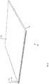
- FIG. 1 shows the body 1 of a car with a cooling device 2 according to the invention.
- the cooling device is embodied as a shallow panel with an inner space 10 and is bounded on the top side by car roof 3 and on the underside by a horizontal wall 4 which, compared to usual cars, takes the place of the so-called roof lining.
- the inner surface of lower wall 4 is provided with a liquid-retaining layer 5, consisting for instance of Portland cement or a thin layer of fibre material.
- the layer thicknesses can for instance be in the order of 0.1-0.3 mm.
- a suitable, easily evaporating liquid, for instance water, is fed to layer 5 by an arrangement of sprayers 6 which provide for a uniform moistening of layer 5.
- the sprayers receive water via a conduit system (not shown) connected to a conduit 24 and a supply tank 22 with a filler cap 28. Water can be fed under pressure intermittently, in accordance with requirement, to sprayers 6 by means of a simple pump 23, for instance a pump of the type used to deliver windscreen washer fluid.
- fans 7 Arranged at a suitable location are fans 7 which blow air, indicated with arrows 8, drawn from the cab of the car into space 10 via the hollow jambs 9 such that the inblown air 8 flows over the moistened layer 5 and leaves device 2 at the rear as according to arrows 11, likewise via hollow jambs 9.
- the water present in this layer 5 evaporates, this having in known manner a strong cooling effect.
- Wall 4 is hereby cooled.
- a wall is thus placed in the vicinity of the head of the users which has a lower temperature than the air toward which it is directed, thereby creating a net radiation absorbing effect, moreover in the vicinity of the head, relatively the greatest radiator and certainly the most sensitive in respect of perception of cold and heat.
- the process air is discharged to the outside. The reason for this is that the space in the cab of a car is so limited that the air humidity can increase quickly here due to the water evaporated because of the cooling, and this can be unpleasant.
- Fans 7 are placed as overpressure fans, therefore on the upstream side of device 2.
- fans 7 could also be placed as underpressure or suction fans, and could therefore be disposed on the downstream side of device 2.
- Figure 2 shows a variant in which the intake airflow 8 is not generated by fan means as in figure 1 , but via favourably placed outflow openings to the outside world 125 and 126 placed at a location in the outer side of the car where underpressure or a very high air speed prevails during driving, whereby the outflowing air 11 is suctioned away and airflow 8 is thereby drawn into space 10.
- outlet openings 113 Situated on the rear side of space 10 are outlet openings 113 which can be opened and closed by means of flaps 125 operated by actuators 126.
- the cooling device according to figure 2 will only function in the case of a substantial vehicle speed.
- FIG 3 shows an embodiment wherein use is made of both fans 7 and outflow openings 113.
- the small fan in the middle jamb is omitted, while the airflow from the fan arranged on the front side of the vehicle nevertheless provides for airflow at that location.
- Fans 7 could otherwise be accommodated directly in lower wall 4.
- FIG 4 shows an embodiment wherein the heat-conducting lower wall is provided with a water-dispersing and/or water-retaining layer, for instance a thin layer of Portland cement, over about half its length in the flow direction of the air from the intake side.
- the sprayers 6 are placed only in this zone.
- these are placed distributed in a regular arrangement over the whole surface.
- the second half of the lower wall, warmer than the first half can then reheat the throughfed, moistened and, in ideal conditions, cooled air, whereby the temperature of the second half of the lower plate decreases while the solubility of water vapour increases due to the raised air temperature, thereby decreasing the danger of condensation in space 10.
- Figure 5 shows a variant of the embodiment according to figure 4 , wherein surface area-enlarging means 14 are arranged on the downstream side on the heat-conducting lower wall.
- Such fins can for instance be manufactured from a heat-conductive material such as copper or aluminium.
- Figure 6 shows an embodiment wherein precipitation, in particular rainwater, is collected via a receptacle 29 which drains into a reservoir 22, which can moreover be provided with a filler cap, via a conduit 30 and via roof gutter 31 via a conduit 30 into for instance a second reservoir 22 which is also provided with a filler cap 28 with a pump 23 and a conduit 24 connecting to the conduit system (not shown) and sprayers 6, wherein connecting conduit 32 supplies the water from roof gutter 31 on the other side.
- a receptacle 29 which drains into a reservoir 22, which can moreover be provided with a filler cap, via a conduit 30 and via roof gutter 31 via a conduit 30 into for instance a second reservoir 22 which is also provided with a filler cap 28 with a pump 23 and a conduit 24 connecting to the conduit system (not shown) and sprayers 6, wherein connecting conduit 32 supplies the water from roof gutter 31 on the other side.
- the device according to figure 3 in a car can thus operate without external energy supply, or optionally with very low energy consumption, i.e. the optional consumption of fan means 7.
- Such panels built into a roof of a car are for instance known from the German car manufacturer Audi. Audi supplies as option a sunroof which, with a sufficient irradiation by sunlight, powers an electric fan which ventilates the interior during parking, whereby the temperature in the interior increases less extremely than in the case of a non-ventilated cab.
- Such a known system does not in fact cool, it merely ventilates.
- Figures 7 and 8 show a panel-like cooling device 15 according to the invention intended for instance for hanging on a ceiling of for recessed placing therein. Where applicable and useful, the same reference numerals are used in figures 7 and 8 as in figure 1 .
- device 15 comprises two tangential fans 16 which have a small diameter and have a length amounting to about half the width of device 15.
- the device has two compartments separated from each other by a vertical dividing wall 17. In the context of the invention this principle is more generally applicable in respect of the use of modularity.
- the upper wall 18 On the blow-out side the upper wall 18 has two outlet slits 19 which debouch into respective plenum chambers 20 which discharge the cooled moistened air 11 via an outlet opening 21, which debouches outside the user space for instance via a conduit.
- fans 16 could also be placed on the outlet side and air drawn in via plenum chambers 20.
- the plenum chambers could be omitted, since the air which is moistened by evaporation of water and which has flowed through chamber 10 will under normal conditions have little effect on the relative air humidity in buildings.
- This device could also be connected to the ventilation device or venting of a building or an optionally present solar chimney, wherein the whole extraction can take place completely passively on the basis of a thermosiphoning effect.
- Figure 9 shows a so-called channel plate 39, a panel constructed from two plates with mutually parallel ribs therebetween, which displays a great similarity to corrugated cardboard and could be used as housing for the cooler in a similar manner as the housing of the cooler according to figure 7 and figure 8 .
- the lower plate 4 in the figure is provided on the side directed toward the inner side of the panel with a moisture-retaining layer 5.
- the second plate of the channel plate forms the wall 18.
- the intermediate ribs can be compared to the dividing wall 17.
- Channel plates can for instance be obtained embodied in polymethyl methacrylate (PMMA), polycarbonate (PC) and polypropylene (PP). This latter embodiment is mainly very thin-walled. Usual embodiments weigh 300-500 gram per square metre at a panel thickness of 3-5 mm.
- Figure 10 shows a variant of the channel plate according to figure 9 .
- Lower plate 4 is now for instance a metal plate on which a second metal plate 40 is arranged with more or less U-shaped channels.
- a moisture-retaining layer 5 is arranged in the channels on the side of extended surface 4 directed toward second plate 40.
- the moisture-retaining layer 5 is moistened by first carrying the cooling medium, for instance water, as according to arrows 41 through the U-shaped channels and discharging it as according to arrows 42. Air from the user space is then carried through the U-shaped channels as according to arrows 41 and discharged as according to arrows 42.
- the cooling medium for instance water
- Figure 11 shows a cooler similar to that of figures 8 and 9 which is laid on a tabletop 44.
- plate 4 now faces upward. Coolant, for instance water, is fed intermittently from water reservoir 43 to the channels of channel plate 39 as according to figure 9 in order to moisten the moisture-retaining layer 5 (not shown).
- the tangential fan 16 carries air through the channels of channel plate 39 so that plate 4 cools due to the extraction of heat of evaporation due to evaporation of the coolant.
- Figure 12 shows a partly cut-away view of a cooler similar to that of figure 11 , wherein an axial fan 48 blows air through channel plate 39 via a plenum chamber 47. Plate 4 once again faces upward here.
- Coolant for instance water, drips via suitably dimensioned holes out of reservoir 45 into the channels of channel plate 39 for the purpose of moistening the moisture-retaining layer 5 not shown in the drawing.
- Possible excess coolant is collected in reservoir 46.
- the coolant can be pumped back from reservoir 46 to reservoir 45 or flow back by means of capillary action to reservoir 45. It is also possible to envisage the excess coolant being poured back manually into reservoir 45.
- This cooler could in this embodiment also be laid on a tabletop.
- a ceiling plate is once again created if channel plate 39 is rotated through 180° over the longitudinal axis of the channels.
- a transparent cooler can be made by making use of for instance glass, PMMA and PC as material for the plates of the chamber which are important for operation and through which air is carried and on which according to 5 a moisture-retaining layer which is transparent, such as for instance a transparent, hygroscopic polymer, is arranged on the relevant sides.
- Another means for reducing the surface tension of the coolant could also be used instead of a moisture-retaining layer 5. It is possible here to envisage a slowly self-sacrificing layer of a soap-like substance, a surface treatment such as a corona treatment or surface roughening.
- moisture-retaining layer can also be wholly transparent, certainly when they are moistened to some extent.
- the coolant for instance water, being visible could moreover have a placebo effect on the people in the user space.
Landscapes
- Engineering & Computer Science (AREA)
- Mechanical Engineering (AREA)
- Life Sciences & Earth Sciences (AREA)
- Sustainable Development (AREA)
- Chemical & Material Sciences (AREA)
- Combustion & Propulsion (AREA)
- General Engineering & Computer Science (AREA)
- Physics & Mathematics (AREA)
- Thermal Sciences (AREA)
- Devices For Blowing Cold Air, Devices For Blowing Warm Air, And Means For Preventing Water Condensation In Air Conditioning Units (AREA)
- Air Humidification (AREA)
Priority Applications (1)
| Application Number | Priority Date | Filing Date | Title |
|---|---|---|---|
| PL10701571T PL2379949T3 (pl) | 2009-01-18 | 2010-01-18 | Urządzenie chłodzące |
Applications Claiming Priority (2)
| Application Number | Priority Date | Filing Date | Title |
|---|---|---|---|
| NL2002424 | 2009-01-18 | ||
| PCT/NL2010/050025 WO2010082828A2 (en) | 2009-01-18 | 2010-01-18 | Cooling device |
Publications (2)
| Publication Number | Publication Date |
|---|---|
| EP2379949A2 EP2379949A2 (en) | 2011-10-26 |
| EP2379949B1 true EP2379949B1 (en) | 2020-02-26 |
Family
ID=41263994
Family Applications (1)
| Application Number | Title | Priority Date | Filing Date |
|---|---|---|---|
| EP10701571.1A Active EP2379949B1 (en) | 2009-01-18 | 2010-01-18 | Cooling device |
Country Status (6)
| Country | Link |
|---|---|
| US (1) | US9829207B2 (pl) |
| EP (1) | EP2379949B1 (pl) |
| ES (1) | ES2791424T3 (pl) |
| NL (1) | NL2004107C2 (pl) |
| PL (1) | PL2379949T3 (pl) |
| WO (1) | WO2010082828A2 (pl) |
Families Citing this family (13)
| Publication number | Priority date | Publication date | Assignee | Title |
|---|---|---|---|---|
| US9517681B2 (en) * | 2009-08-21 | 2016-12-13 | Martin A. Alpert | Apparatus and method for radiant heating and cooling for vehicles |
| EP2413050A1 (en) * | 2010-07-28 | 2012-02-01 | Hendrik Boekhout | System for influencing temperature of buildings or apparatus |
| US9370882B2 (en) * | 2010-10-22 | 2016-06-21 | Tata Technologies Pte Limited | Cost effective and efficient air circulation system for a vehicle having rotomolded body assembly |
| CN102358143A (zh) * | 2011-07-29 | 2012-02-22 | 齐峰 | 汽车空调系统 |
| CN102358144B (zh) * | 2011-08-23 | 2014-08-20 | 童明伟 | 水循环式车用辐射板空调系统 |
| US9958173B1 (en) * | 2011-09-08 | 2018-05-01 | Northwest Renewable Energy Corp. | Solar powered roof ventilation system |
| KR101586776B1 (ko) * | 2012-03-28 | 2016-01-19 | 도요타 지도샤(주) | 차량용 공조 장치 |
| JP6289881B2 (ja) * | 2013-11-26 | 2018-03-07 | 株式会社前川製作所 | 車両用空調装置 |
| US11219192B2 (en) * | 2015-12-16 | 2022-01-11 | Purdue Research Foundation | Systems and methods for cooling an animal |
| CN106864214B (zh) * | 2017-04-10 | 2023-03-31 | 福建农林大学 | 汽车仪表台降温装置及其工作方法 |
| AT521450A1 (de) * | 2018-06-17 | 2020-01-15 | Enio Gmbh | Kompakte adiabatische kühlanlage mit strahlungsanteil |
| DE102021204387A1 (de) | 2021-04-30 | 2022-11-03 | Volkswagen Aktiengesellschaft | Fahrzeug mit Brennstoffzellenantrieb, wobei der Brennstoffzellenantrieb eine Wasserableitung aufweist und eine mittels Verdunstung von Wasser gekühlte Fahrgastzelle |
| WO2025217540A1 (en) * | 2024-04-12 | 2025-10-16 | Whiskey Lima Corporation | System and method for monitoring and purging atmosphere in a confined space |
Citations (2)
| Publication number | Priority date | Publication date | Assignee | Title |
|---|---|---|---|---|
| DE19512048A1 (de) * | 1995-03-31 | 1996-10-02 | Behr Gmbh & Co | Fahrzeugklimatisierungseinrichtung |
| DE20312603U1 (de) * | 2003-08-14 | 2004-01-15 | Kickelhayn, Horst | Anordnung zur Verbesserung der Raumatmosphäre in einem Tunnelbau, insbesondere einer U-Bahnstation |
Family Cites Families (63)
| Publication number | Priority date | Publication date | Assignee | Title |
|---|---|---|---|---|
| NL56913C (pl) | ||||
| US2151097A (en) * | 1935-09-09 | 1939-03-21 | Evans Prod Co | Means and method for cooling vehicle bodies |
| GB464415A (en) | 1935-10-17 | 1937-04-19 | Frank Herbert | Improvements in and relating to the cooling of moving vehicles |
| US2213421A (en) * | 1937-06-16 | 1940-09-03 | Niagara Blower Co | Evaporative cooling system |
| US2276970A (en) * | 1940-04-23 | 1942-03-17 | Hibberd Frederick Hyde | Air conditioning system |
| FR938013A (fr) | 1944-08-05 | 1948-09-02 | Ingbureauv H E Handl Nv | Frigidaire |
| US2552819A (en) | 1946-07-08 | 1951-05-15 | Schwarzmayr Ludwig | Refrigerating device for cars |
| FR935697A (fr) | 1946-10-31 | 1948-06-28 | Appareil rafraichisseur ménager | |
| BE510847A (pl) | 1951-04-23 | |||
| US3524398A (en) * | 1968-06-17 | 1970-08-18 | John C Winfrey | Air conditioning system for vehicle operator enclosure |
| US3738621A (en) * | 1969-11-10 | 1973-06-12 | Everkool Inc | Evaporative cooler |
| US3606982A (en) * | 1969-11-10 | 1971-09-21 | Everkool Inc | Evaporative cooler |
| US3964268A (en) * | 1974-10-03 | 1976-06-22 | Diperi Leonard J | Energy conservation housing |
| US4261930A (en) * | 1976-06-14 | 1981-04-14 | Byco Sales, Ltd. | Evaporative cooling system |
| US4094935A (en) * | 1976-12-03 | 1978-06-13 | Walker Manufacturing Company | Evaporative cooling system |
| FR2467761A1 (fr) * | 1979-10-18 | 1981-04-30 | Lyon Roland | Climatiseur par evaporation d'eau pour cabines d'engins |
| JPS57179553A (en) | 1981-04-27 | 1982-11-05 | Mitsubishi Electric Corp | Air-cooling method through evaporation and cooling of water |
| US6327994B1 (en) * | 1984-07-19 | 2001-12-11 | Gaudencio A. Labrador | Scavenger energy converter system its new applications and its control systems |
| JPH0759993B2 (ja) | 1988-06-30 | 1995-06-28 | 株式会社小松製作所 | 輻射型局所冷房機 |
| IL85817A (en) * | 1988-03-22 | 1993-03-15 | Dsb Eng Ltd | Evaporative cooler |
| WO1990015956A1 (fr) | 1989-06-15 | 1990-12-27 | Kabushiki Kaisha Komatsu Seisakusho | Lieu de travail equipe d'une paroi de climatisation radiante |
| US4953831A (en) * | 1989-06-21 | 1990-09-04 | Cool Pet Industries, Inc. | Evaporative air cooler |
| US5112535A (en) * | 1990-09-07 | 1992-05-12 | Roberson Joe E | Vehicle having a cooling system |
| US5361600A (en) * | 1991-08-02 | 1994-11-08 | Kelley Franklyn F | Evaporative cooler with scrubber system |
| US5168722A (en) * | 1991-08-16 | 1992-12-08 | Walton Enterprises Ii, L.P. | Off-road evaporative air cooler |
| US5187946A (en) * | 1991-09-24 | 1993-02-23 | Yefim Rotenberg | Apparatus & Method for indirect evaporative cooling of a fluid |
| US5315843A (en) * | 1992-08-13 | 1994-05-31 | Acma Limited | Evaporative air conditioner unit |
| US5529536A (en) * | 1994-06-07 | 1996-06-25 | Sizemore; Timothy J. | Evaporative cooling/humidifing of a motor vehicle's interior air, utilizing the vehicle's as designed powered ventalation system |
| US5453223A (en) * | 1994-09-12 | 1995-09-26 | Acma Limited | Method of air cooling and heat exchange apparatus |
| GR1002913B (el) * | 1997-05-15 | 1998-05-25 | Συστημα ατμοψυξεως | |
| ES2159486B1 (es) * | 1999-04-12 | 2002-05-01 | Col Ven Sa | Climatizador de aire para cabinas de transportes y metodo para instalarlo sobre un techo inclinado. |
| ES2159485B1 (es) * | 1999-04-12 | 2002-05-01 | Col Ven Sa | Unidad evaporadora para climatizador de aire |
| AU6228999A (en) | 1999-10-22 | 2001-04-30 | Seft Development Laboratory Co., Ltd. | Cooling device |
| US6776001B2 (en) * | 2000-02-07 | 2004-08-17 | Idalex Technologies, Inc. | Method and apparatus for dew point evaporative product cooling |
| US6497107B2 (en) * | 2000-07-27 | 2002-12-24 | Idalex Technologies, Inc. | Method and apparatus of indirect-evaporation cooling |
| US6408633B1 (en) * | 2000-08-08 | 2002-06-25 | Instatherm Company | Interfacing of thermal storage systems with air conditioning units |
| JP4423792B2 (ja) * | 2000-09-14 | 2010-03-03 | 株式会社デンソー | 沸騰冷却装置 |
| US6705096B2 (en) * | 2000-09-27 | 2004-03-16 | Idalex Technologies, Inc. | Method and plate apparatus for dew point evaporative cooler using a trough wetting system |
| US6581402B2 (en) * | 2000-09-27 | 2003-06-24 | Idalex Technologies, Inc. | Method and plate apparatus for dew point evaporative cooler |
| US20020078704A1 (en) * | 2000-12-26 | 2002-06-27 | Stich John L. | Two stage evaporative cooling apparatus |
| US6915654B2 (en) * | 2001-06-20 | 2005-07-12 | Ross Johnson | Portable cooling mechanism |
| US6669556B2 (en) * | 2001-10-16 | 2003-12-30 | James Cameron Gautney | Outdoor fan system |
| US20030136143A1 (en) * | 2002-01-24 | 2003-07-24 | Robert Edwin Johnson | Evaporative cooling device |
| US6546744B1 (en) * | 2002-02-28 | 2003-04-15 | Billy Cavender | Recreational vehicle heat transfer apparatus |
| US6546743B1 (en) * | 2002-07-02 | 2003-04-15 | Marcus Ray Sullivan | Mobile cooling apparatus |
| US20060032258A1 (en) * | 2002-08-23 | 2006-02-16 | Roger Pruitt | Cooling assembly |
| GB0324348D0 (en) | 2003-10-17 | 2003-11-19 | Oxycom Bv | Heat exchange laminate |
| FR2865795B1 (fr) * | 2004-01-30 | 2006-04-07 | Dominique Christian Ausseil | Refroidisseur/conditionneur d'air |
| DK1716369T3 (da) * | 2004-02-18 | 2010-08-23 | Idalex Technologies Inc | Pladevarme- og masseveksler med kantforlængelse |
| KR100607204B1 (ko) * | 2004-06-18 | 2006-08-01 | (주) 위젠글로벌 | 냉각유체의 증발 냉각방법 및 그 장치 |
| JP3796505B2 (ja) * | 2004-07-29 | 2006-07-12 | シャープ株式会社 | 冷却庫 |
| US7395676B2 (en) * | 2004-08-10 | 2008-07-08 | Steve White | Collapsible misting fan apparatus |
| CN101365916A (zh) * | 2005-10-18 | 2009-02-11 | 梅德克朗股份公司 | 能量消耗少的空调系统 |
| US20070089448A1 (en) * | 2005-10-20 | 2007-04-26 | Portable Misting Systems, Llc | Portable misting system |
| GB0600274D0 (en) * | 2006-01-09 | 2006-02-15 | Oxycell Holding Bv | Cooling and ventilation device |
| US7654307B2 (en) * | 2006-01-18 | 2010-02-02 | Delphi Technologies, Inc. | Evaporative cooler assisted automotive air conditioning system |
| US20080041083A1 (en) * | 2006-08-15 | 2008-02-21 | Al-Garni Ahmed Z | Low-cost air conditioning system for open area |
| KR101013896B1 (ko) * | 2007-10-25 | 2011-02-14 | 현대자동차주식회사 | 차량용 쿨링시스템 |
| WO2010011687A2 (en) * | 2008-07-21 | 2010-01-28 | Idalex Technologies, Inc. | Fabrication materials and techniques for plate heat and mass exchangers for indirect evaporative coolers |
| AU2008359842B2 (en) * | 2008-07-22 | 2013-05-02 | A.T.E. Enterprises Private Limited | Systems and methods for indirect evaporative cooling and for two stage evaporative cooling |
| KR101367021B1 (ko) * | 2012-05-23 | 2014-02-24 | 삼성전기주식회사 | 전력 모듈용 방열 시스템 |
| US20150343881A1 (en) * | 2014-05-27 | 2015-12-03 | Alliance For Sustainable Energy, Llc | Evaporative cooling cycling using water condensate formed in a vapor-compression a/c system evaporator |
| US10336160B2 (en) * | 2015-08-11 | 2019-07-02 | Fernando Celso Sodre Vergamini | Vehicular cooling system |
-
2010
- 2010-01-18 US US13/144,573 patent/US9829207B2/en not_active Expired - Fee Related
- 2010-01-18 NL NL2004107A patent/NL2004107C2/nl not_active IP Right Cessation
- 2010-01-18 WO PCT/NL2010/050025 patent/WO2010082828A2/en not_active Ceased
- 2010-01-18 ES ES10701571T patent/ES2791424T3/es active Active
- 2010-01-18 EP EP10701571.1A patent/EP2379949B1/en active Active
- 2010-01-18 PL PL10701571T patent/PL2379949T3/pl unknown
Patent Citations (2)
| Publication number | Priority date | Publication date | Assignee | Title |
|---|---|---|---|---|
| DE19512048A1 (de) * | 1995-03-31 | 1996-10-02 | Behr Gmbh & Co | Fahrzeugklimatisierungseinrichtung |
| DE20312603U1 (de) * | 2003-08-14 | 2004-01-15 | Kickelhayn, Horst | Anordnung zur Verbesserung der Raumatmosphäre in einem Tunnelbau, insbesondere einer U-Bahnstation |
Also Published As
| Publication number | Publication date |
|---|---|
| PL2379949T3 (pl) | 2020-08-10 |
| NL2004107C2 (nl) | 2010-11-10 |
| US9829207B2 (en) | 2017-11-28 |
| WO2010082828A3 (en) | 2010-10-07 |
| US20110269388A1 (en) | 2011-11-03 |
| ES2791424T3 (es) | 2020-11-04 |
| EP2379949A2 (en) | 2011-10-26 |
| NL2004107A (nl) | 2010-07-20 |
| WO2010082828A2 (en) | 2010-07-22 |
Similar Documents
| Publication | Publication Date | Title |
|---|---|---|
| EP2379949B1 (en) | Cooling device | |
| US10739025B1 (en) | Air cooling system for a building structure | |
| EP2679922B1 (en) | Heat pump system and air-conditioner | |
| WO2011033325A1 (en) | Cooling, heating, surface-radiating and air exchanging building system with low energy consumption for energy-saving houses with increased passive quality | |
| WO2016189457A1 (en) | Covering unit of an external space. | |
| JP2016217630A (ja) | 放射空調システム | |
| JP2002180558A (ja) | 建 物 | |
| JP6208194B2 (ja) | 空調換気システム | |
| WO2018066994A1 (en) | Method and devices for building cooling | |
| CN216114414U (zh) | 除湿装置及具有除湿功能的取暖器 | |
| JP5228344B2 (ja) | 換気空調装置 | |
| JP6811543B2 (ja) | 放射冷暖房装置 | |
| JP2007506930A (ja) | 夏及び冬両方において適切な温度で少なくとも1つの空気の流れを生成する加熱及び空調デバイス | |
| JP4605759B2 (ja) | 建物の室内空調システム | |
| JP6668548B1 (ja) | クールベンチシステム | |
| JP6811542B2 (ja) | 放射冷暖房システム | |
| JP4351175B2 (ja) | 壁面設置又は自立式パネル型冷暖房装置 | |
| JP4698204B2 (ja) | 建物の室内空調システム | |
| JP2008075922A (ja) | 調湿冷暖房装置及びそれを用いた空間構造 | |
| JP2008281285A (ja) | 空気調和システム及び建物 | |
| JPH0669621U (ja) | スポットクーラー | |
| GB2373849A (en) | Ventilation heat exchanger | |
| CN108444008A (zh) | 一种房间采暖用风机盘管散热器及热量释放方法 | |
| JP2002121832A (ja) | 建築物 | |
| JP4869447B1 (ja) | 冷暖房システム |
Legal Events
| Date | Code | Title | Description |
|---|---|---|---|
| PUAI | Public reference made under article 153(3) epc to a published international application that has entered the european phase |
Free format text: ORIGINAL CODE: 0009012 |
|
| 17P | Request for examination filed |
Effective date: 20110706 |
|
| AK | Designated contracting states |
Kind code of ref document: A2 Designated state(s): AT BE BG CH CY CZ DE DK EE ES FI FR GB GR HR HU IE IS IT LI LT LU LV MC MK MT NL NO PL PT RO SE SI SK SM TR |
|
| DAX | Request for extension of the european patent (deleted) | ||
| RAP1 | Party data changed (applicant data changed or rights of an application transferred) |
Owner name: LUX ET LIBERTAS B.V. |
|
| RIN1 | Information on inventor provided before grant (corrected) |
Inventor name: LUX ET LIBERTAS B.V. |
|
| STAA | Information on the status of an ep patent application or granted ep patent |
Free format text: STATUS: EXAMINATION IS IN PROGRESS |
|
| 17Q | First examination report despatched |
Effective date: 20170808 |
|
| GRAP | Despatch of communication of intention to grant a patent |
Free format text: ORIGINAL CODE: EPIDOSNIGR1 |
|
| STAA | Information on the status of an ep patent application or granted ep patent |
Free format text: STATUS: GRANT OF PATENT IS INTENDED |
|
| INTG | Intention to grant announced |
Effective date: 20190424 |
|
| RIN1 | Information on inventor provided before grant (corrected) |
Inventor name: MEULENBELT, MATTHIJS DIRK |
|
| GRAJ | Information related to disapproval of communication of intention to grant by the applicant or resumption of examination proceedings by the epo deleted |
Free format text: ORIGINAL CODE: EPIDOSDIGR1 |
|
| STAA | Information on the status of an ep patent application or granted ep patent |
Free format text: STATUS: EXAMINATION IS IN PROGRESS |
|
| GRAP | Despatch of communication of intention to grant a patent |
Free format text: ORIGINAL CODE: EPIDOSNIGR1 |
|
| STAA | Information on the status of an ep patent application or granted ep patent |
Free format text: STATUS: GRANT OF PATENT IS INTENDED |
|
| INTC | Intention to grant announced (deleted) | ||
| INTG | Intention to grant announced |
Effective date: 20190912 |
|
| GRAS | Grant fee paid |
Free format text: ORIGINAL CODE: EPIDOSNIGR3 |
|
| GRAA | (expected) grant |
Free format text: ORIGINAL CODE: 0009210 |
|
| STAA | Information on the status of an ep patent application or granted ep patent |
Free format text: STATUS: THE PATENT HAS BEEN GRANTED |
|
| AK | Designated contracting states |
Kind code of ref document: B1 Designated state(s): AT BE BG CH CY CZ DE DK EE ES FI FR GB GR HR HU IE IS IT LI LT LU LV MC MK MT NL NO PL PT RO SE SI SK SM TR |
|
| REG | Reference to a national code |
Ref country code: GB Ref legal event code: FG4D |
|
| REG | Reference to a national code |
Ref country code: CH Ref legal event code: EP |
|
| REG | Reference to a national code |
Ref country code: DE Ref legal event code: R096 Ref document number: 602010063224 Country of ref document: DE |
|
| REG | Reference to a national code |
Ref country code: AT Ref legal event code: REF Ref document number: 1238100 Country of ref document: AT Kind code of ref document: T Effective date: 20200315 |
|
| REG | Reference to a national code |
Ref country code: IE Ref legal event code: FG4D |
|
| REG | Reference to a national code |
Ref country code: SE Ref legal event code: TRGR |
|
| REG | Reference to a national code |
Ref country code: NL Ref legal event code: FP |
|
| PG25 | Lapsed in a contracting state [announced via postgrant information from national office to epo] |
Ref country code: NO Free format text: LAPSE BECAUSE OF FAILURE TO SUBMIT A TRANSLATION OF THE DESCRIPTION OR TO PAY THE FEE WITHIN THE PRESCRIBED TIME-LIMIT Effective date: 20200526 Ref country code: FI Free format text: LAPSE BECAUSE OF FAILURE TO SUBMIT A TRANSLATION OF THE DESCRIPTION OR TO PAY THE FEE WITHIN THE PRESCRIBED TIME-LIMIT Effective date: 20200226 |
|
| REG | Reference to a national code |
Ref country code: LT Ref legal event code: MG4D |
|
| PG25 | Lapsed in a contracting state [announced via postgrant information from national office to epo] |
Ref country code: IS Free format text: LAPSE BECAUSE OF FAILURE TO SUBMIT A TRANSLATION OF THE DESCRIPTION OR TO PAY THE FEE WITHIN THE PRESCRIBED TIME-LIMIT Effective date: 20200626 Ref country code: LV Free format text: LAPSE BECAUSE OF FAILURE TO SUBMIT A TRANSLATION OF THE DESCRIPTION OR TO PAY THE FEE WITHIN THE PRESCRIBED TIME-LIMIT Effective date: 20200226 Ref country code: HR Free format text: LAPSE BECAUSE OF FAILURE TO SUBMIT A TRANSLATION OF THE DESCRIPTION OR TO PAY THE FEE WITHIN THE PRESCRIBED TIME-LIMIT Effective date: 20200226 Ref country code: GR Free format text: LAPSE BECAUSE OF FAILURE TO SUBMIT A TRANSLATION OF THE DESCRIPTION OR TO PAY THE FEE WITHIN THE PRESCRIBED TIME-LIMIT Effective date: 20200527 Ref country code: BG Free format text: LAPSE BECAUSE OF FAILURE TO SUBMIT A TRANSLATION OF THE DESCRIPTION OR TO PAY THE FEE WITHIN THE PRESCRIBED TIME-LIMIT Effective date: 20200526 |
|
| PG25 | Lapsed in a contracting state [announced via postgrant information from national office to epo] |
Ref country code: PT Free format text: LAPSE BECAUSE OF FAILURE TO SUBMIT A TRANSLATION OF THE DESCRIPTION OR TO PAY THE FEE WITHIN THE PRESCRIBED TIME-LIMIT Effective date: 20200719 Ref country code: RO Free format text: LAPSE BECAUSE OF FAILURE TO SUBMIT A TRANSLATION OF THE DESCRIPTION OR TO PAY THE FEE WITHIN THE PRESCRIBED TIME-LIMIT Effective date: 20200226 Ref country code: LT Free format text: LAPSE BECAUSE OF FAILURE TO SUBMIT A TRANSLATION OF THE DESCRIPTION OR TO PAY THE FEE WITHIN THE PRESCRIBED TIME-LIMIT Effective date: 20200226 Ref country code: SK Free format text: LAPSE BECAUSE OF FAILURE TO SUBMIT A TRANSLATION OF THE DESCRIPTION OR TO PAY THE FEE WITHIN THE PRESCRIBED TIME-LIMIT Effective date: 20200226 Ref country code: EE Free format text: LAPSE BECAUSE OF FAILURE TO SUBMIT A TRANSLATION OF THE DESCRIPTION OR TO PAY THE FEE WITHIN THE PRESCRIBED TIME-LIMIT Effective date: 20200226 Ref country code: SM Free format text: LAPSE BECAUSE OF FAILURE TO SUBMIT A TRANSLATION OF THE DESCRIPTION OR TO PAY THE FEE WITHIN THE PRESCRIBED TIME-LIMIT Effective date: 20200226 Ref country code: DK Free format text: LAPSE BECAUSE OF FAILURE TO SUBMIT A TRANSLATION OF THE DESCRIPTION OR TO PAY THE FEE WITHIN THE PRESCRIBED TIME-LIMIT Effective date: 20200226 Ref country code: CZ Free format text: LAPSE BECAUSE OF FAILURE TO SUBMIT A TRANSLATION OF THE DESCRIPTION OR TO PAY THE FEE WITHIN THE PRESCRIBED TIME-LIMIT Effective date: 20200226 |
|
| REG | Reference to a national code |
Ref country code: ES Ref legal event code: FG2A Ref document number: 2791424 Country of ref document: ES Kind code of ref document: T3 Effective date: 20201104 |
|
| REG | Reference to a national code |
Ref country code: AT Ref legal event code: MK05 Ref document number: 1238100 Country of ref document: AT Kind code of ref document: T Effective date: 20200226 |
|
| REG | Reference to a national code |
Ref country code: DE Ref legal event code: R097 Ref document number: 602010063224 Country of ref document: DE |
|
| PLBE | No opposition filed within time limit |
Free format text: ORIGINAL CODE: 0009261 |
|
| STAA | Information on the status of an ep patent application or granted ep patent |
Free format text: STATUS: NO OPPOSITION FILED WITHIN TIME LIMIT |
|
| PG25 | Lapsed in a contracting state [announced via postgrant information from national office to epo] |
Ref country code: AT Free format text: LAPSE BECAUSE OF FAILURE TO SUBMIT A TRANSLATION OF THE DESCRIPTION OR TO PAY THE FEE WITHIN THE PRESCRIBED TIME-LIMIT Effective date: 20200226 |
|
| 26N | No opposition filed |
Effective date: 20201127 |
|
| PG25 | Lapsed in a contracting state [announced via postgrant information from national office to epo] |
Ref country code: SI Free format text: LAPSE BECAUSE OF FAILURE TO SUBMIT A TRANSLATION OF THE DESCRIPTION OR TO PAY THE FEE WITHIN THE PRESCRIBED TIME-LIMIT Effective date: 20200226 |
|
| PG25 | Lapsed in a contracting state [announced via postgrant information from national office to epo] |
Ref country code: MC Free format text: LAPSE BECAUSE OF FAILURE TO SUBMIT A TRANSLATION OF THE DESCRIPTION OR TO PAY THE FEE WITHIN THE PRESCRIBED TIME-LIMIT Effective date: 20200226 |
|
| REG | Reference to a national code |
Ref country code: CH Ref legal event code: PL |
|
| PG25 | Lapsed in a contracting state [announced via postgrant information from national office to epo] |
Ref country code: LU Free format text: LAPSE BECAUSE OF NON-PAYMENT OF DUE FEES Effective date: 20210118 |
|
| PG25 | Lapsed in a contracting state [announced via postgrant information from national office to epo] |
Ref country code: LI Free format text: LAPSE BECAUSE OF NON-PAYMENT OF DUE FEES Effective date: 20210131 Ref country code: CH Free format text: LAPSE BECAUSE OF NON-PAYMENT OF DUE FEES Effective date: 20210131 |
|
| PG25 | Lapsed in a contracting state [announced via postgrant information from national office to epo] |
Ref country code: IE Free format text: LAPSE BECAUSE OF NON-PAYMENT OF DUE FEES Effective date: 20210118 |
|
| PG25 | Lapsed in a contracting state [announced via postgrant information from national office to epo] |
Ref country code: HU Free format text: LAPSE BECAUSE OF FAILURE TO SUBMIT A TRANSLATION OF THE DESCRIPTION OR TO PAY THE FEE WITHIN THE PRESCRIBED TIME-LIMIT; INVALID AB INITIO Effective date: 20100118 Ref country code: CY Free format text: LAPSE BECAUSE OF FAILURE TO SUBMIT A TRANSLATION OF THE DESCRIPTION OR TO PAY THE FEE WITHIN THE PRESCRIBED TIME-LIMIT Effective date: 20200226 |
|
| P01 | Opt-out of the competence of the unified patent court (upc) registered |
Effective date: 20230504 |
|
| P02 | Opt-out of the competence of the unified patent court (upc) changed |
Effective date: 20230512 |
|
| PGFP | Annual fee paid to national office [announced via postgrant information from national office to epo] |
Ref country code: NL Payment date: 20240116 Year of fee payment: 15 |
|
| PGFP | Annual fee paid to national office [announced via postgrant information from national office to epo] |
Ref country code: ES Payment date: 20240208 Year of fee payment: 15 |
|
| PG25 | Lapsed in a contracting state [announced via postgrant information from national office to epo] |
Ref country code: MK Free format text: LAPSE BECAUSE OF FAILURE TO SUBMIT A TRANSLATION OF THE DESCRIPTION OR TO PAY THE FEE WITHIN THE PRESCRIBED TIME-LIMIT Effective date: 20200226 |
|
| PGFP | Annual fee paid to national office [announced via postgrant information from national office to epo] |
Ref country code: DE Payment date: 20240123 Year of fee payment: 15 Ref country code: GB Payment date: 20240122 Year of fee payment: 15 |
|
| PGFP | Annual fee paid to national office [announced via postgrant information from national office to epo] |
Ref country code: SE Payment date: 20240117 Year of fee payment: 15 Ref country code: PL Payment date: 20240110 Year of fee payment: 15 Ref country code: IT Payment date: 20240118 Year of fee payment: 15 Ref country code: FR Payment date: 20240117 Year of fee payment: 15 Ref country code: BE Payment date: 20240116 Year of fee payment: 15 |
|
| PG25 | Lapsed in a contracting state [announced via postgrant information from national office to epo] |
Ref country code: TR Free format text: LAPSE BECAUSE OF FAILURE TO SUBMIT A TRANSLATION OF THE DESCRIPTION OR TO PAY THE FEE WITHIN THE PRESCRIBED TIME-LIMIT Effective date: 20200226 |
|
| PG25 | Lapsed in a contracting state [announced via postgrant information from national office to epo] |
Ref country code: MT Free format text: LAPSE BECAUSE OF FAILURE TO SUBMIT A TRANSLATION OF THE DESCRIPTION OR TO PAY THE FEE WITHIN THE PRESCRIBED TIME-LIMIT Effective date: 20200226 |
|
| REG | Reference to a national code |
Ref country code: DE Ref legal event code: R119 Ref document number: 602010063224 Country of ref document: DE |
|
| REG | Reference to a national code |
Ref country code: SE Ref legal event code: EUG |
|
| REG | Reference to a national code |
Ref country code: NL Ref legal event code: MM Effective date: 20250201 |
|
| GBPC | Gb: european patent ceased through non-payment of renewal fee |
Effective date: 20250118 |
|
| PG25 | Lapsed in a contracting state [announced via postgrant information from national office to epo] |
Ref country code: DE Free format text: LAPSE BECAUSE OF NON-PAYMENT OF DUE FEES Effective date: 20250801 |
|
| PG25 | Lapsed in a contracting state [announced via postgrant information from national office to epo] |
Ref country code: NL Free format text: LAPSE BECAUSE OF NON-PAYMENT OF DUE FEES Effective date: 20250201 |
|
| PG25 | Lapsed in a contracting state [announced via postgrant information from national office to epo] |
Ref country code: BE Free format text: LAPSE BECAUSE OF NON-PAYMENT OF DUE FEES Effective date: 20250131 Ref country code: GB Free format text: LAPSE BECAUSE OF NON-PAYMENT OF DUE FEES Effective date: 20250118 |
|
| PG25 | Lapsed in a contracting state [announced via postgrant information from national office to epo] |
Ref country code: FR Free format text: LAPSE BECAUSE OF NON-PAYMENT OF DUE FEES Effective date: 20250131 |
|
| REG | Reference to a national code |
Ref country code: BE Ref legal event code: MM Effective date: 20250131 |
|
| PG25 | Lapsed in a contracting state [announced via postgrant information from national office to epo] |
Ref country code: IT Free format text: LAPSE BECAUSE OF NON-PAYMENT OF DUE FEES Effective date: 20250118 |