EP2679922B1 - Heat pump system and air-conditioner - Google Patents
Heat pump system and air-conditioner Download PDFInfo
- Publication number
- EP2679922B1 EP2679922B1 EP13189788.6A EP13189788A EP2679922B1 EP 2679922 B1 EP2679922 B1 EP 2679922B1 EP 13189788 A EP13189788 A EP 13189788A EP 2679922 B1 EP2679922 B1 EP 2679922B1
- Authority
- EP
- European Patent Office
- Prior art keywords
- air
- heat
- pump system
- heat pump
- radiation plate
- Prior art date
- Legal status (The legal status is an assumption and is not a legal conclusion. Google has not performed a legal analysis and makes no representation as to the accuracy of the status listed.)
- Active
Links
- 230000005855 radiation Effects 0.000 claims description 74
- 239000003507 refrigerant Substances 0.000 claims description 19
- XLYOFNOQVPJJNP-UHFFFAOYSA-N water Substances O XLYOFNOQVPJJNP-UHFFFAOYSA-N 0.000 claims description 17
- 230000005494 condensation Effects 0.000 claims description 13
- 238000009833 condensation Methods 0.000 claims description 13
- 230000000694 effects Effects 0.000 claims description 8
- 230000001681 protective effect Effects 0.000 claims description 8
- 230000002093 peripheral effect Effects 0.000 claims description 3
- 230000003313 weakening effect Effects 0.000 claims description 2
- 238000010438 heat treatment Methods 0.000 description 16
- 238000001816 cooling Methods 0.000 description 14
- 238000009434 installation Methods 0.000 description 13
- 238000005265 energy consumption Methods 0.000 description 7
- 238000010276 construction Methods 0.000 description 5
- 238000011084 recovery Methods 0.000 description 5
- 238000004378 air conditioning Methods 0.000 description 2
- 230000001143 conditioned effect Effects 0.000 description 2
- 238000007599 discharging Methods 0.000 description 2
- 239000007788 liquid Substances 0.000 description 2
- 229910052751 metal Inorganic materials 0.000 description 2
- 239000002184 metal Substances 0.000 description 2
- 238000000034 method Methods 0.000 description 2
- 238000013021 overheating Methods 0.000 description 2
- RYGMFSIKBFXOCR-UHFFFAOYSA-N Copper Chemical compound [Cu] RYGMFSIKBFXOCR-UHFFFAOYSA-N 0.000 description 1
- 241000276425 Xiphophorus maculatus Species 0.000 description 1
- 229910052782 aluminium Inorganic materials 0.000 description 1
- XAGFODPZIPBFFR-UHFFFAOYSA-N aluminium Chemical compound [Al] XAGFODPZIPBFFR-UHFFFAOYSA-N 0.000 description 1
- 230000002301 combined effect Effects 0.000 description 1
- 229910052802 copper Inorganic materials 0.000 description 1
- 239000010949 copper Substances 0.000 description 1
- 238000007791 dehumidification Methods 0.000 description 1
- 230000002441 reversible effect Effects 0.000 description 1
- 238000009423 ventilation Methods 0.000 description 1
Images


Classifications
-
- F—MECHANICAL ENGINEERING; LIGHTING; HEATING; WEAPONS; BLASTING
- F25—REFRIGERATION OR COOLING; COMBINED HEATING AND REFRIGERATION SYSTEMS; HEAT PUMP SYSTEMS; MANUFACTURE OR STORAGE OF ICE; LIQUEFACTION SOLIDIFICATION OF GASES
- F25B—REFRIGERATION MACHINES, PLANTS OR SYSTEMS; COMBINED HEATING AND REFRIGERATION SYSTEMS; HEAT PUMP SYSTEMS
- F25B30/00—Heat pumps
-
- F—MECHANICAL ENGINEERING; LIGHTING; HEATING; WEAPONS; BLASTING
- F24—HEATING; RANGES; VENTILATING
- F24F—AIR-CONDITIONING; AIR-HUMIDIFICATION; VENTILATION; USE OF AIR CURRENTS FOR SCREENING
- F24F1/00—Room units for air-conditioning, e.g. separate or self-contained units or units receiving primary air from a central station
- F24F1/0007—Indoor units, e.g. fan coil units
- F24F1/0059—Indoor units, e.g. fan coil units characterised by heat exchangers
-
- F—MECHANICAL ENGINEERING; LIGHTING; HEATING; WEAPONS; BLASTING
- F24—HEATING; RANGES; VENTILATING
- F24F—AIR-CONDITIONING; AIR-HUMIDIFICATION; VENTILATION; USE OF AIR CURRENTS FOR SCREENING
- F24F12/00—Use of energy recovery systems in air conditioning, ventilation or screening
- F24F12/001—Use of energy recovery systems in air conditioning, ventilation or screening with heat-exchange between supplied and exhausted air
- F24F12/002—Use of energy recovery systems in air conditioning, ventilation or screening with heat-exchange between supplied and exhausted air using an intermediate heat-transfer fluid
- F24F12/003—Use of energy recovery systems in air conditioning, ventilation or screening with heat-exchange between supplied and exhausted air using an intermediate heat-transfer fluid using a heat pump
-
- F—MECHANICAL ENGINEERING; LIGHTING; HEATING; WEAPONS; BLASTING
- F24—HEATING; RANGES; VENTILATING
- F24F—AIR-CONDITIONING; AIR-HUMIDIFICATION; VENTILATION; USE OF AIR CURRENTS FOR SCREENING
- F24F12/00—Use of energy recovery systems in air conditioning, ventilation or screening
- F24F12/001—Use of energy recovery systems in air conditioning, ventilation or screening with heat-exchange between supplied and exhausted air
- F24F12/006—Use of energy recovery systems in air conditioning, ventilation or screening with heat-exchange between supplied and exhausted air using an air-to-air heat exchanger
-
- F—MECHANICAL ENGINEERING; LIGHTING; HEATING; WEAPONS; BLASTING
- F24—HEATING; RANGES; VENTILATING
- F24F—AIR-CONDITIONING; AIR-HUMIDIFICATION; VENTILATION; USE OF AIR CURRENTS FOR SCREENING
- F24F3/00—Air-conditioning systems in which conditioned primary air is supplied from one or more central stations to distributing units in the rooms or spaces where it may receive secondary treatment; Apparatus specially designed for such systems
- F24F3/001—Air-conditioning systems in which conditioned primary air is supplied from one or more central stations to distributing units in the rooms or spaces where it may receive secondary treatment; Apparatus specially designed for such systems in which the air treatment in the central station takes place by means of a heat-pump or by means of a reversible cycle
-
- F—MECHANICAL ENGINEERING; LIGHTING; HEATING; WEAPONS; BLASTING
- F24—HEATING; RANGES; VENTILATING
- F24F—AIR-CONDITIONING; AIR-HUMIDIFICATION; VENTILATION; USE OF AIR CURRENTS FOR SCREENING
- F24F5/00—Air-conditioning systems or apparatus not covered by F24F1/00 or F24F3/00, e.g. using solar heat or combined with household units such as an oven or water heater
- F24F5/0007—Air-conditioning systems or apparatus not covered by F24F1/00 or F24F3/00, e.g. using solar heat or combined with household units such as an oven or water heater cooling apparatus specially adapted for use in air-conditioning
- F24F5/001—Compression cycle type
-
- F—MECHANICAL ENGINEERING; LIGHTING; HEATING; WEAPONS; BLASTING
- F24—HEATING; RANGES; VENTILATING
- F24F—AIR-CONDITIONING; AIR-HUMIDIFICATION; VENTILATION; USE OF AIR CURRENTS FOR SCREENING
- F24F5/00—Air-conditioning systems or apparatus not covered by F24F1/00 or F24F3/00, e.g. using solar heat or combined with household units such as an oven or water heater
- F24F5/0089—Systems using radiation from walls or panels
-
- F—MECHANICAL ENGINEERING; LIGHTING; HEATING; WEAPONS; BLASTING
- F24—HEATING; RANGES; VENTILATING
- F24F—AIR-CONDITIONING; AIR-HUMIDIFICATION; VENTILATION; USE OF AIR CURRENTS FOR SCREENING
- F24F3/00—Air-conditioning systems in which conditioned primary air is supplied from one or more central stations to distributing units in the rooms or spaces where it may receive secondary treatment; Apparatus specially designed for such systems
- F24F2003/003—Air-conditioning systems in which conditioned primary air is supplied from one or more central stations to distributing units in the rooms or spaces where it may receive secondary treatment; Apparatus specially designed for such systems with primary air treatment in the central station and subsequent secondary air treatment in air treatment units located in or near the rooms
-
- F—MECHANICAL ENGINEERING; LIGHTING; HEATING; WEAPONS; BLASTING
- F24—HEATING; RANGES; VENTILATING
- F24F—AIR-CONDITIONING; AIR-HUMIDIFICATION; VENTILATION; USE OF AIR CURRENTS FOR SCREENING
- F24F13/00—Details common to, or for air-conditioning, air-humidification, ventilation or use of air currents for screening
- F24F13/22—Means for preventing condensation or evacuating condensate
- F24F13/222—Means for preventing condensation or evacuating condensate for evacuating condensate
- F24F2013/227—Condensate pipe for drainage of condensate from the evaporator
-
- F—MECHANICAL ENGINEERING; LIGHTING; HEATING; WEAPONS; BLASTING
- F24—HEATING; RANGES; VENTILATING
- F24F—AIR-CONDITIONING; AIR-HUMIDIFICATION; VENTILATION; USE OF AIR CURRENTS FOR SCREENING
- F24F2203/00—Devices or apparatus used for air treatment
- F24F2203/02—System or Device comprising a heat pump as a subsystem, e.g. combined with humidification/dehumidification, heating, natural energy or with hybrid system
-
- Y—GENERAL TAGGING OF NEW TECHNOLOGICAL DEVELOPMENTS; GENERAL TAGGING OF CROSS-SECTIONAL TECHNOLOGIES SPANNING OVER SEVERAL SECTIONS OF THE IPC; TECHNICAL SUBJECTS COVERED BY FORMER USPC CROSS-REFERENCE ART COLLECTIONS [XRACs] AND DIGESTS
- Y02—TECHNOLOGIES OR APPLICATIONS FOR MITIGATION OR ADAPTATION AGAINST CLIMATE CHANGE
- Y02B—CLIMATE CHANGE MITIGATION TECHNOLOGIES RELATED TO BUILDINGS, e.g. HOUSING, HOUSE APPLIANCES OR RELATED END-USER APPLICATIONS
- Y02B30/00—Energy efficient heating, ventilation or air conditioning [HVAC]
- Y02B30/52—Heat recovery pumps, i.e. heat pump based systems or units able to transfer the thermal energy from one area of the premises or part of the facilities to a different one, improving the overall efficiency
-
- Y—GENERAL TAGGING OF NEW TECHNOLOGICAL DEVELOPMENTS; GENERAL TAGGING OF CROSS-SECTIONAL TECHNOLOGIES SPANNING OVER SEVERAL SECTIONS OF THE IPC; TECHNICAL SUBJECTS COVERED BY FORMER USPC CROSS-REFERENCE ART COLLECTIONS [XRACs] AND DIGESTS
- Y02—TECHNOLOGIES OR APPLICATIONS FOR MITIGATION OR ADAPTATION AGAINST CLIMATE CHANGE
- Y02B—CLIMATE CHANGE MITIGATION TECHNOLOGIES RELATED TO BUILDINGS, e.g. HOUSING, HOUSE APPLIANCES OR RELATED END-USER APPLICATIONS
- Y02B30/00—Energy efficient heating, ventilation or air conditioning [HVAC]
- Y02B30/56—Heat recovery units
Definitions
- the present application relates to an air-conditioner, and in particular, to a heat pump system according to claim 1 and an air-conditioner according to claim 3.
- the air-conditioner generally refers herein to a room air conditioner, and specifically is a set for providing conditioned air into a room (or an enclosed space or area). Most of conventional air-conditioners perform cooling or heating in the room in convective heat-transfer manner.
- a fan coil may serve as the terminal unit of an air-conditioner.
- a fan is provided in the fan coil in advance. Air in the region of the fan coil is circulated continuously under the action of the fan.
- the air is cooled or heated after flowing through a refrigerant coil or a hot-water (or chilled-water) coil, thereby cooling or heating the room. Because cooling or heating is achieved in the convective heat-transfer manner, the indoor temperature is not uniform. Either cooling or heating, the indoor temperature difference is generally greater than 10 degrees centigrade, even more than 20 degrees centigrade. Part of the cool or hot airflow is too large, which results in uncomfortableness of a human body, local cold, or even illness.
- a radiation coil is adopted at the terminal of air-conditioner.
- the radiation coil is provided therein with chilled water (or hot water), and is arranged on the surface structure of the building (the ceiling surface or the ground surface).
- the chilled water (or hot water) in the radiation coil cools or heats a particular area in radiating manner.
- Such a structure of air-conditioner achieves the uniform cooling or heating to a certain extent, however, the water circulation loop of the radiation coil is required to exchange heat with a heat exchanger in a refrigerant loop of an air-conditioner firstly, and then exchange heat with the indoor air, thereby adding an intermediate heat exchange procedure and increasing the energy consumption of a power apparatus for delivering water circulation, for example, a circulating pump.
- the efficiency of heat exchange is low, and the installation of the system is complex.
- US3220212 A discloses an air conditioning unit, which includes a substantially flat box-shaped casing having side- and end walls, an upper wall and a bottom wall, means for connecting the interior of the casing with an external air reservoir and means for conveying an air flow derived from said external air reservoir through the interior of the casing, a heat pump system within the casing including a compressor, at least two heat exchangers and pipes interconnecting the compressor and the heat exchangers and forming a circuit for circulating a refrigerant through the compressor and heat exchangers, at least one of said heat exchangers being arranged in heat exchange relation with said air flow, and at least one other heat exchanger being arranged in heat exchange relation with a radiant heating and cooling panel subjacent the bottom wall of the said casing.
- WO2012099141 A discloses that an air conditioner, which is provided with a refrigerant circuit having a compressor, an indoor heat exchanger, a radiant heat exchanger, a pressure reduction mechanism, and an outdoor heat exchanger.
- the indoor heat exchanger is disposed inside an indoor unit in such a manner as to face an indoor fan, and the radiant heat exchanger is disposed on the outer surface of the indoor unit.
- the air conditioner has an indoor electrically-operated valve for adjusting the amount of refrigerant supplied to the radiant heat exchanger.
- the air conditioner is controlled in such a manner that, when a refrigerant is flushed through the indoor heat exchanger to carry out warm-air heating, and the refrigerant is flushed through the radiant heat exchanger to carry out radiant heating, the opening of the indoor electrically-operated valve becomes larger after the frequency of the compressor drops.
- US5267450 A discloses an air conditioning apparatus including an indoor device having a first heat exchanger, a second heat exchanger, and a radiant panel. Air circulation mode is switched to radiant mode when a room temperature has reached a temperature set by a user. Refrigerant is changeably circulated through the first and second heat exchangers in a cooling operation so that dew is not formed on the radiant panel.
- US3292388 A discloses a radiant heating or cooling system, which includes a combined radiant heating, cooling and ventilation sub-ceiling including a plurality of pipes and a plurality of plate 115 elements in heat exchange association with said pipes, wherein the pipes of the subceiling are inserted in the secondary circuit of a liquid-to-liquid heat exchanger, the primary circuit of which contains a reversible heat 120 pump comprising a compressor, an expansion valve and an air-to-liquid heat exchanger, the components of said heat pump being enclosed in a compartment communicating with the atmosphere and comprising means for causing an air-current derived from the atmosphere to flow through said compartment.
- a reversible heat 120 pump comprising a compressor, an expansion valve and an air-to-liquid heat exchanger
- US6263690 B1 discloses a heat pump system according to the preamble of claim 1.
- a heat pump system includes a main heat pump system, and a directly expanded strong cool-heat radiation plate provided on a building surface and serving as the terminal of the main heat pump system.
- the directly expanded strong cool-heat radiation plate is configured to allow refrigerant in the main heat pump system to circulate therein.
- a heat retaining layer and a reflecting layer are provided on the building surface, and wherein the reflecting layer is provided on an outside surface of the heat retaining layer facing indoors, and the directly expanded strong cool-heat radiation plate is fixed on the building surface by means of a bracket, a decorative face is provided on a side of the directly expanded strong cool-heat radiation plate exposed to the outside, a packed layer with an enclosed cavity structure is located between the decorative face and the directly expanded strong cool-heat radiation plate, the packed layer has a cavity structure with an enclosed space defined by the decorative face, the directly expanded strong cool-heat radiation plate and peripheral structures, a buffer plate, which is used for weakening the transfer effect of cool or heat quantity from the directly expanded strong cool-heat radiation plate to a room, is further provided in the packed layer between the decorative face and the directly expanded strong cool-heat radiation plate
- a protective condensation trough for receiving condensed water is provided below the directly expanded strong cool-heat radiation plate, and is provided therein with a condensate outlet.
- the heat pump system of the present application adopts the directly expanded strong cool-heat radiation plate as the terminal of the main heat pump system
- refrigerant in the main heat pump system may exchange heat with air by means of the directly expanded strong cool-heat radiation plate directly, instead of secondary heat exchange of the refrigerant loop and the water circulation loop, thereby reducing loss in intermediate heat exchange, improving the heat exchange efficiency and heat utilization, and omitting the circulating pump for water circulation so as to lower energy consumption and simplify the installation.
- the present application further discloses an air-conditioner, including a chassis, and the heat pump system according to any one of the above technical solutions.
- the main heat pump system of the heat pump system is provided in the chassis.
- the air-conditioner further includes a replacement air heat pump system provided in the chassis, and a replacement air outlet of the replacement air heat pump system is adapted to be connected to an indoor replacement air intake
- an air heat exchanger is provided between the main heat pump system and the replacement air heat pump system, wherein a first replacement air outlet of the air heat exchanger is connected to a replacement air intake of the replacement air heat pump system, a first return eduction air outlet of the air heat exchanger is connected to a heat source side air intake of the replacement air heat pump system, a second replacement air outlet of the air heat exchanger is connected to a replacement air intake of the main heat pump system, a second return eduction air outlet of the air heat exchanger is connected to a heat source side air intake of the main heat pump system, a return air intake of the air heat exchanger is connected to a return eduction air outlet of the room.
- a multistage air filter is provided at a replacement air intake of the air heat exchanger.
- the return air intake of the air heat exchanger is also connected to a return air pipe arranged in the room.
- a secondary heat exchange of the refrigerant loop and the water circulation loop is needless, thereby reducing loss in intermediate heat exchange, improving the heat exchange efficiency and heat utilization, and omitting the circulating pump for water circulation so as to lower energy consumption and simplify the installation.
- the air-conditioner with the heat pump system also has the corresponding technical effects.
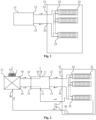
- FIG 1 it is a schematic view of a heat pump system according to an embodiment of the present application.
- the heat pump system includes a main heat pump system 11, and a directly expanded strong cool-heat radiation plate 21 provided on the surface of the building and serving as the terminal of the main heat pump system 11.
- the interior of the directly expanded strong cool-heat radiation plate 21 enables the circulation of refrigerant in the main heat pump system 11.
- an air heat exchanger 51 is provided on the main heat pump system 11. Specifically, a return air intake 56 of the air heat exchanger 51 communicates with a return air outlet 34 of a room 31; a second return air outlet 54 of the air heat exchanger 51 is connected to a heat source side air intake 14 of the main heat pump system 11; a second replacement air outlet 55 of the air heat exchanger 51 communicates with a replacement air intake 15 of the main heat pump system 11; and a replacement air outlet 17 of the main heat pump system 11 communicates with a replacement air intake 35 of the room 31.
- a multistage air filter 7 is further provided at a replacement air intake 57 of the air heat exchanger 51 in order to purify air.
- the working medium in the main heat pump system 11 flows through a working medium feeding pipe into the directly expanded strong cool-heat radiation plate 21 arranged in the room 31.
- the working medium is evaporated as a result of absorbing heat from the room 31 so as to radiate cooling quantity (or condensed as a result of releasing heat into the room 31 so as to radiate heating quantity), and then returns to the main heat pump system 11 through a working medium discharging pipe.
- outdoor fresh air flows into the air heat exchanger 51 via the multistage air filter 7, and makes primary heat exchange with the return air from the room 31 so as to obtain primary pre-cooled and filtered replacement air (or pre-heated and filtered replacement air).
- the primary pre-cooled and filtered replacement air flows into the main heat pump system 11 to be secondarily pre-cooled and dehumidified (or preheated and humidified) so as to form the replacement air which will be supplied into the room 31.
- Return air undergoing primary heat recovery flows through a heat source side air intake 14 into the main heat pump system 11, and return air undergoing secondary full heat recovery is discharged from an eduction air outlet 16 of the main heat pump system 11.
- a return air intake 56 of the air heat exchanger 51 is also connected to a return air pipe 36 disposed in the room 31.
- the return air pipe 36 passes through a return air outlet 34 of the room 31.
- the provision of the return air pipe 36 may avoid the replacement air from short circuit, and improve indoor air quality.
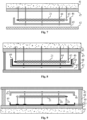
- figures 7 to 10 are schematic views showing the installation of a directly expanded strong cool-heat radiation plate 21 according to embodiments of the present application; and figure 11 is a schematic structural view of a directly expanded strong cool-heat radiation plate 21 according to an embodiment of the present application.
- a heat retaining layer 47 is provided on a building surface 41.
- the directly expanded strong cool-heat radiation plate 21 is fixed to the building surface 41 by means of a bracket 43.
- a reflecting layer is provided on the outside surface of the heat retaining layer 47 which faces towards the interior of the room 31. The provision of the reflecting layer may transfer cool quantity (or heat quantity) radiated from the directly expanded strong cool-heat radiation plate 21 to the room 31 more efficiently.
- the bracket 43 may be varied.
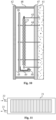
- the bracket 43 may be of a flexible construction or a rigid construction; when the building surface 41 is a ground surface, as shown in figure 9 , in order to ensure an appropriate space for installing a buffer plate 46 with respect to the directly expanded strong cool-heat radiation plate 21, and to ensure the thickness of a packed layer 45 and a firm supported decorative face 42, the bracket 43 is preferably of a rigid construction; and when the building surface 41 is a vertical surface, as shown in figure 10 , similarly, in order to ensure an appropriate space for installing a buffer plate 46 with respect to the directly expanded strong cool-heat radiation plate 21, and to ensure the thickness of a packed layer 45 and a firm supported decorative face 42, the bracket 43 is preferably of a rigid construction.
- the decorative face 42 is provided on the side of the directly expanded strong cool-heat radiation plate 21 which is exposed to the outside, and the packed layer 45 with closed cavity structure is located between the decorative face 42 and the directly expanded strong cool-heat radiation plate 21.
- the decorative face 42 has different name depending on the different building surface 41.
- the building surface 41 is a ceiling surface
- the decorative face 42 is the ceiling or any face with ornamental effect.
- the building surface 41 is a ground surface
- the decorative face 42 is a floor, and specifically, the floor could be lithoid floor, tile floor, metal floor, or wooden floor, etc.
- the decorative face 42 is a false wall layer with ornamental effect.
- the packed layer 45 has a cavity structure with an enclosed space defined by the decorative face 42, the directly expanded strong cool-heat radiation plate 21 and peripheral structures. Since the packed layer 45 is located between the decorative face 42 and the directly expanded strong cool-heat radiation plate 21, it is possible to relieve the occurrence of moisture condensation because of local overcooling or the occurrence of overheating of the directly expanded strong cool-heat radiation plate 21 effectively in the cold or heat radiating process.
- the temperature of the decorative face 42 is more uniform. The comfortable feeling in the room 31 is thus improved.
- the buffer plate 46 is located between the packed layer 45 and the directly expanded strong cool-heat radiation plate 21.
- the buffer plate 46 is fixed to the building surface 41 by means of a bracket 44.
- the provision of the buffer plate 46 could weaken the transfer effect of cool or heat quantity from the directly expanded strong cool-heat radiation plate 21 to the room 31.
- the directly expanded strong cool-heat radiation plate 21 achieves secondary heat radiation under the combined effect of the buffer plate 46 and the packed layer 45, so that the temperature of the decorative face 42 further tends to be uniform. The comfortable feeling in the room 31 is thus improved further.
- an protective condensation trough 49 for receiving condensed water is provided below the directly expanded strong cool-heat radiation plate 21, and is provided therein with a condensate outlet 40.
- the protective condensation trough 49 is provided on the buffer plate 46 entirely; as shown in figure 9 , when the building surface 41 is a ground surface, the protective condensation trough 49 is provided on the heat retaining layer 47 entirely; and as shown in figure 10 , when the building surface 41 is a vertical surface, the protective condensation trough 49 is provided at the lower portion of the buffer plate 46.
- a supporter 48 adapted for supporting the decorative face 42 is provided between the decorative face 42 and the building surface 41.
- the supporters 48 may be arranged around the directly expanded strong cool-heat radiation plate 21, so as to separate the building surface 41 with the directly expanded strong cool-heat radiation plate 21 thereon from the building surface 41 without the directly expanded strong cool-heat radiation plate 21 thereon.
- the directly expanded strong cool-heat radiation plate 21 may include various effective heat transfer structures in which a refrigerant pipeline (copper pipe, aluminum pipe, etc.) and a fixed pipeline may be formed with the radiating surfaces.
- the radiating surfaces may be a metal plate or a surface cooler, etc.
- the directly expanded strong cool-heat radiation plate 21 may also be of a platy structure with various refrigerant cavity which may transfer heat effectively.
- the refrigerant in the main heat pump system 11 may be circulated in the plate, and a working medium inlet 22 and a working medium outlet 23 are provided in the directly expanded strong cool-heat radiation plate 21.
- the directly expanded strong cool-heat radiation plate 21 may be a single piece or multiple pieces. In case of multiple pieces, a plurality of the directly expanded strong cool-heat radiation plate 21 are interconnected in series or in parallel.
- the directly expanded strong cool-heat radiation plate 21 in the air-conditioner disclosed in the embodiments of the application exchanges heat with the room 31 directly, the intensity of the cooling and heating radiation is large, and the directly expanded strong cool-heat radiation plate 21 is mounted on a reduced area with ease. It is possible to ensure the cooling and heating quantity needed for comfortable feeling in the room 31, reduce the area of the room 31 for radiation, and have no effect on the use of space of the room 31.
- the air-conditioner includes a chassis (not marked in the figures), and the main heat pump system 11 of the heat pump system in the above any solution is provided in the chassis.
- the working medium outlet 12 of the main heat pump system 11 communicates with the working medium inlet 22 of the directly expanded strong cool-heat radiation plate 21 via a working medium feeding pipe, and the working medium feeding pipe extends through an installation port 32 of the room 31.
- a working medium return intake 13 of the main heat pump system 11 communicates with the working medium outlet 23 of the directly expanded strong cool-heat radiation plate 21 via a working medium return pipe, and the working medium return pipe extends through the installation port 33 of the room 31.
- the installation port 32 and the installation port 33 may be the same installation port.
- the refrigerant in the main heat pump system 11 exchanges heat via the directly expanded strong cool-heat radiation plate 21 directly, instead of secondary heat exchange of the refrigerant loop and the water circulation loop, thereby reducing loss in intermediate heat exchange, improving the heat exchange efficiency and heat utilization, and omitting the circulating pump for water circulation so as to lower energy consumption and simplify the installation.
- the main heat pump system may undertake both sensible heat load (radiation heat transfer) and latent heat load (replacement air pre-cooled dehumidification or preheated humidification) in the room 31.
- a replacement air heat pump system 61 is provided in the chassis of the air-conditioner.
- a replacement air outlet 63 of the replacement air heat pump system 61 is adapted to be connected to the replacement air intake 35 of the room 31. If the room 31 is kept in a good temperature condition, or the sensible heat load is low, the main heat pump system 11 may be intermittently operated generally.
- the replacement air heat pump system 61 in the embodiment of the present application may filter pre-cooled dehumidified replacement air or may preheat (humidify) the replacement air such as to meet the desired humidity and quality.
- the air heat exchanger 51 is arranged between the main heat pump system 11 and the replacement air heat pump system 61.
- a first replacement air outlet 53 of the air heat exchanger 51 is connected to a replacement air intake 64 of the replacement air heat pump system 61;
- a first return eduction air outlet 52 of the air heat exchanger 51 is connected to a heat source side air intake 65 of the replacement air heat pump system 61;
- the second replacement air outlet 55 of the air heat exchanger 51 is connected to the replacement air intake 15 of the main heat pump system 11;
- the second return eduction air outlet 54 of the air heat exchanger 51 is connected to the heat source side air intake 14 of the main heat pump system 11;
- the return air intake 56 of the air heat exchanger 51 is connected to the return eduction air outlet 34 of the room 31;
- the replacement air outlet 63 of the replacement air heat pump system 61 communicates with the replacement air intake 35 of the room 31.
- a multistage air filter 7 is provided at
- outdoor fresh air flows into the air heat exchanger 51 via the multistage air filter 7, and makes primary heat exchange with the return air from the room 31 so as to obtain primary pre-cooled (or pre-heated) and filtered replacement air, a part of which flows into the replacement air heat pump system 61, and the other part of which flows into the main heat pump system 11 to be secondarily pre-cooled and dehumidified (or preheated and humidified) so as to form the replacement air which will be supplied into the room 31.
- the replacement air intake 35, the return eduction air outlet 34, and the return air pipe 36 need to be arranged in the room 31.
- the temperature in the room 31 is uniform, without the blown feeling and the noise of the apparatus.
- the replacement air heat pump system 61 the conditioned air in the room 31 is fresh, has stable humidity and clean environment, thereby greatly improving the comfort in the room.
- such an facility is easy to be installed, and may achieve a strong cooling radiation with a large temperature difference without moisture condensation, nor a strong heating radiation with a large temperature difference without dry and hot feeling, and may have a power of the facility reducing more than fifty percent than the conventional air-conditioner.
- the use of the air heat exchanger 51 enables an efficient full cool-heat recovery in the replacement air system, a simple structure, small volume, and a low cost.
Description
- The present application relates to an air-conditioner, and in particular, to a heat pump system according to claim 1 and an air-conditioner according to claim 3.
- The air-conditioner generally refers herein to a room air conditioner, and specifically is a set for providing conditioned air into a room (or an enclosed space or area). Most of conventional air-conditioners perform cooling or heating in the room in convective heat-transfer manner. Specifically, a fan coil may serve as the terminal unit of an air-conditioner. A fan is provided in the fan coil in advance. Air in the region of the fan coil is circulated continuously under the action of the fan. The air is cooled or heated after flowing through a refrigerant coil or a hot-water (or chilled-water) coil, thereby cooling or heating the room. Because cooling or heating is achieved in the convective heat-transfer manner, the indoor temperature is not uniform. Either cooling or heating, the indoor temperature difference is generally greater than 10 degrees centigrade, even more than 20 degrees centigrade. Part of the cool or hot airflow is too large, which results in uncomfortableness of a human body, local cold, or even illness.
- In order to solve the above problem, a radiation coil is adopted at the terminal of air-conditioner. The radiation coil is provided therein with chilled water (or hot water), and is arranged on the surface structure of the building (the ceiling surface or the ground surface). The chilled water (or hot water) in the radiation coil cools or heats a particular area in radiating manner. Such a structure of air-conditioner achieves the uniform cooling or heating to a certain extent, however, the water circulation loop of the radiation coil is required to exchange heat with a heat exchanger in a refrigerant loop of an air-conditioner firstly, and then exchange heat with
the indoor air, thereby adding an intermediate heat exchange procedure and increasing the energy consumption of a power apparatus for delivering water circulation, for example, a circulating pump. Thus, the efficiency of heat exchange is low, and the installation of the system is complex. - In conclusion, it is desirable for the person skilled in the art to improve the efficiency of heat exchange.
-
US3220212 A discloses an air conditioning unit, which includes a substantially flat box-shaped casing having side- and end walls, an upper wall and a bottom wall, means for connecting the interior of the casing with an external air reservoir and means for conveying an air flow derived from said external air reservoir through the interior of the casing, a heat pump system within the casing including a compressor, at least two heat exchangers and pipes interconnecting the compressor and the heat exchangers and forming a circuit for circulating a refrigerant through the compressor and heat exchangers, at least one of said heat exchangers being arranged in heat exchange relation with said air flow, and at least one other heat exchanger being arranged in heat exchange relation with a radiant heating and cooling panel subjacent the bottom wall of the said casing. -
WO2012099141 A discloses that an air conditioner, which is provided with a refrigerant circuit having a compressor, an indoor heat exchanger, a radiant heat exchanger, a pressure reduction mechanism, and an outdoor heat exchanger. The indoor heat exchanger is disposed inside an indoor unit in such a manner as to face an indoor fan, and the radiant heat exchanger is disposed on the outer surface of the indoor unit. In addition, the air conditioner has an indoor electrically-operated valve for adjusting the amount of refrigerant supplied to the radiant heat exchanger. The air conditioner is controlled in such a manner that, when a refrigerant is flushed through the indoor heat exchanger to carry out warm-air heating, and the refrigerant is flushed through the radiant heat exchanger to carry out radiant heating, the opening of the indoor electrically-operated valve becomes larger after the frequency of the compressor drops. -
US5267450 A discloses an air conditioning apparatus including an indoor device having a first heat exchanger, a second heat exchanger, and a radiant panel. Air circulation mode is switched to radiant mode when a room temperature has reached a temperature set by a user. Refrigerant is changeably circulated through the first and second heat exchangers in a cooling operation so that dew is not formed on the radiant panel. -
US3292388 A discloses a radiant heating or cooling system, which includes a combined radiant heating, cooling and ventilation sub-ceiling including a plurality of pipes and a plurality of plate 115 elements in heat exchange association with said pipes, wherein the pipes of the subceiling are inserted in the secondary circuit of a liquid-to-liquid heat exchanger, the primary circuit of which contains a reversible heat 120 pump comprising a compressor, an expansion valve and an air-to-liquid heat exchanger, the components of said heat pump being enclosed in a compartment communicating with the atmosphere and comprising means for causing an air-current derived from the atmosphere to flow through said compartment. -
US6263690 B1 discloses a heat pump system according to the preamble of claim 1. - In view of the above fact, there are provided according to the present application a heat pump system and an air-conditioner which may increase the efficiency of heat exchange. In order to achieve the above objects, the following technical solutions are set forth in the present application.
- A heat pump system includes a main heat pump system, and a directly expanded strong cool-heat radiation plate provided on a building surface and serving as the terminal of the main heat pump system. The directly expanded strong cool-heat radiation plate is configured to allow refrigerant in the main heat pump system to circulate therein. A heat retaining layer and a reflecting layer are provided on the building surface, and wherein the reflecting layer is provided on an outside surface of the heat retaining layer facing indoors, and the directly expanded strong cool-heat radiation plate is fixed on the building surface by means of a bracket, a decorative face is provided on a side of the directly expanded strong cool-heat radiation plate exposed to the outside, a packed layer with an enclosed cavity structure is located between the decorative face and the directly expanded strong cool-heat radiation plate, the packed layer has a cavity structure with an enclosed space defined by the decorative face, the directly expanded strong cool-heat radiation plate and peripheral structures, a buffer plate, which is used for weakening the transfer effect of cool or heat quantity from the directly expanded strong cool-heat radiation plate to a room, is further provided in the packed layer between the decorative face and the directly expanded strong cool-heat radiation plate
- Preferably, in the heat pump system, a protective condensation trough for receiving condensed water is provided below the directly expanded strong cool-heat radiation plate, and is provided therein with a condensate outlet.
- Compared with the air-conditioner in the prior art, since the heat pump system of the present application adopts the directly expanded strong cool-heat radiation plate as the terminal of the main heat pump system, refrigerant in the main heat pump system may exchange heat with air by means of the directly expanded strong cool-heat radiation plate directly, instead of secondary heat exchange of the refrigerant loop and the water circulation loop, thereby reducing loss in intermediate heat exchange, improving the heat exchange efficiency and heat utilization, and omitting the circulating pump for water circulation so as to lower energy consumption and simplify the installation.
- The present application further discloses an air-conditioner, including a chassis, and the heat pump system according to any one of the above technical solutions. The main heat pump system of the heat pump system is provided in the chassis.
- Preferably, the air-conditioner further includes a replacement air heat pump system provided in the chassis, and a replacement air outlet of the replacement air heat pump system is adapted to be connected to an indoor replacement air intake
- Preferably, in the air-conditioner, an air heat exchanger is provided between the main heat pump system and the replacement air heat pump system, wherein a first replacement air outlet of the air heat exchanger is connected to a replacement air intake of the replacement air heat pump system, a first return eduction air outlet of the air heat exchanger is connected to a heat source side air intake of the replacement air heat pump system, a second replacement air outlet of the air heat exchanger is connected to a replacement air intake of the main heat pump system, a second return eduction air outlet of the air heat exchanger is connected to a heat source side air intake of the main heat pump system, a return air intake of the air heat exchanger is connected to
a return eduction air outlet of the room. - Preferably, in the air-conditioner, a multistage air filter is provided at a replacement air intake of the air heat exchanger.
- Preferably, in the air-conditioner, the return air intake of the air heat exchanger is also connected to a return air pipe arranged in the room.
- A secondary heat exchange of the refrigerant loop and the water circulation loop is needless, thereby reducing loss in intermediate heat exchange, improving the heat exchange efficiency and heat utilization, and omitting the circulating pump for water circulation so as to lower energy consumption and simplify the installation. In the event that the heat pump system has the above technical effects, the air-conditioner with the heat pump system also has the corresponding technical effects.
- To illustrate embodiments of the present application or the technical solution in the prior art more clearly, drawings used in description of the embodiments or the prior art will be described briefly below. Obviously, the drawings described below are only directed to some of the embodiments of the application, and the person skilled in the art may achieve other drawings according to such drawings without creative efforts.
-
Figure 1 is a schematic view of a heat pump system according to the invention: -
Figures 2 to 6 are schematic views of an air-conditioner according to the invention; -
Figures 7 to 10 are schematic views showing the installation of a directly expanded strong cool-heat radiation plate according to the invention; and -
Figure 11 is a schematic structural view of a directly expanded strong cool-heat radiation plate according to the invention. - Hereinafter, the embodiments will be described in conjunction with the drawings. Furthermore, the embodiments illustrated below have no any limitation to inventive contents recited in claims, and are not necessary in its entirety for solutions of inventions defined in the claims.
- There are provided in the present application a heat pump system and an air-conditioner which may reduce energy consumption of the air conditioner.
- Referring to
figure 1 , it is a schematic view of a heat pump system according to an embodiment of the present application. - The heat pump system includes a main
heat pump system 11, and a directly expanded strong cool-heat radiation plate 21 provided on the surface of the building and serving as the terminal of the mainheat pump system 11. The interior of the directly expanded strong cool-heat radiation plate 21 enables the circulation of refrigerant in the mainheat pump system 11. - For the purpose of saving energy further, as shown in
figure 2 , anair heat exchanger 51 is provided on the mainheat pump system 11. Specifically, areturn air intake 56 of theair heat exchanger 51 communicates with areturn air outlet 34 of aroom 31; a secondreturn air outlet 54 of theair heat exchanger 51 is connected to a heat sourceside air intake 14 of the mainheat pump system 11; a secondreplacement air outlet 55 of theair heat exchanger 51 communicates with areplacement air intake 15 of the mainheat pump system 11; and areplacement air outlet 17 of the mainheat pump system 11 communicates with areplacement air intake 35 of theroom 31. - A
multistage air filter 7 is further provided at areplacement air intake 57 of theair heat exchanger 51 in order to purify air. - When the main
heat pump system 11 is running, the working medium in the mainheat pump system 11 flows through a working medium feeding pipe into the directly expanded strong cool-heat radiation plate 21 arranged in theroom 31. The working medium is evaporated as a result of absorbing heat from theroom 31 so as to radiate cooling quantity (or condensed as a result of releasing heat into theroom 31 so as to radiate heating quantity), and then returns to the mainheat pump system 11 through a working medium discharging pipe. At the same time, outdoor fresh air flows into theair heat exchanger 51 via themultistage air filter 7, and makes primary heat exchange with the return air from theroom 31 so as to obtain primary pre-cooled and filtered replacement air (or pre-heated and filtered replacement air). Then, the primary pre-cooled and filtered replacement air flows into the mainheat pump system 11 to be secondarily pre-cooled and dehumidified (or preheated and humidified) so as to form the replacement air which will be supplied into theroom 31. Return air undergoing primary heat recovery flows through a heat sourceside air intake 14 into the mainheat pump system 11, and return air undergoing secondary full heat recovery is discharged from aneduction air outlet 16 of the mainheat pump system 11. - In order to improve the comfortable feeling in the room, a
return air intake 56 of theair heat exchanger 51 is also connected to areturn air pipe 36 disposed in theroom 31. Thereturn air pipe 36 passes through areturn air outlet 34 of theroom 31. The provision of thereturn air pipe 36 may avoid the replacement air from short circuit, and improve indoor air quality. - Referring to
figures 7 to 11, figures 7 to 10 are schematic views showing the installation of a directly expanded strong cool-heat radiation plate 21 according to embodiments of the present application; andfigure 11 is a schematic structural view of a directly expanded strong cool-heat radiation plate 21 according to an embodiment of the present application. - In order to reduce the loss of cool or heat quantity, a
heat retaining layer 47 is provided on abuilding surface 41. The directly expanded strong cool-heat radiation plate 21 is fixed to thebuilding surface 41 by means of abracket 43. In order to reduce the dissipation of cool or heat quantity, a reflecting layer is provided on the outside surface of theheat retaining layer 47 which faces towards the interior of theroom 31. The provision of the reflecting layer may transfer cool quantity (or heat quantity) radiated from the directly expanded strong cool-heat radiation plate 21 to theroom 31 more efficiently. When the directly expanded strong cool-heat radiation plate 21 is provided on adifferent building surface 41, thebracket 43 may be varied. When thebuilding surface 41 is a ceiling surface, as shown infigures 7 and 8 , thebracket 43 may be of a flexible construction or a rigid construction; when thebuilding surface 41 is a ground surface, as shown infigure 9 , in order to ensure an appropriate space for installing abuffer plate 46 with respect to the directly expanded strong cool-heat radiation plate 21, and to ensure the thickness of a packedlayer 45 and a firm supporteddecorative face 42, thebracket 43 is preferably of a rigid construction; and when thebuilding surface 41 is a vertical surface, as shown infigure 10 , similarly, in order to ensure an appropriate space for installing abuffer plate 46 with respect to the directly expanded strong cool-heat radiation plate 21, and to ensure the thickness of a packedlayer 45 and a firm supporteddecorative face 42, thebracket 43 is preferably of a rigid construction. - To ensure the aesthetic appearance of the
room 31 after the directly expanded strong cool-heat radiation plate 21 is mounted, thedecorative face 42 is provided on the side of the directly expanded strong cool-heat radiation plate 21 which is exposed to the outside, and the packedlayer 45 with closed cavity structure is located between thedecorative face 42 and the directly expanded strong cool-heat radiation plate 21. Thedecorative face 42 has different name depending on thedifferent building surface 41. When thebuilding surface 41 is a ceiling surface, thedecorative face 42 is the ceiling or any face with ornamental effect. When thebuilding surface 41 is a ground surface, thedecorative face 42 is a floor, and specifically, the floor could be lithoid floor, tile floor, metal floor, or wooden floor, etc. When thebuilding surface 41 is a vertical surface, thedecorative face 42 is a false wall layer with ornamental effect. - The packed
layer 45 has a cavity structure with an enclosed space defined by thedecorative face 42, the directly expanded strong cool-heat radiation plate 21 and peripheral structures. Since the packedlayer 45 is located between thedecorative face 42 and the directly expanded strong cool-heat radiation plate 21, it is possible to relieve the occurrence of moisture condensation because of local overcooling or the occurrence of overheating of the directly expanded strong cool-heat radiation plate 21 effectively in the cold or heat radiating process. The temperature of thedecorative face 42 is more uniform. The comfortable feeling in theroom 31 is thus improved. - In order to further relieve the occurrence of moisture condensation because of local overcooling or the occurrence of overheating, the
buffer plate 46 is located between the packedlayer 45 and the directly expanded strong cool-heat radiation plate 21. Thebuffer plate 46 is fixed to thebuilding surface 41 by means of abracket 44. The provision of thebuffer plate 46 could weaken the transfer effect of cool or heat quantity from the directly expanded strong cool-heat radiation plate 21 to theroom 31. When the main heat pump system performs refrigerating (or heating), the directly expanded strong cool-heat radiation plate 21 achieves secondary heat radiation under the combined effect of thebuffer plate 46 and the packedlayer 45, so that the temperature of thedecorative face 42 further tends to be uniform. The comfortable feeling in theroom 31 is thus improved further. - In a further technical solution, in order to prevent damage to inner parts because of moisture condensation in enclosed space of assembly of the directly expanded strong cool-
heat radiation plate 21, anprotective condensation trough 49 for receiving condensed water is provided below the directly expanded strong cool-heat radiation plate 21, and is provided therein with acondensate outlet 40. When the moisture condensation of the directly expanded strong cool-heat radiation plate 21 occurs, it will be collected in theprotective condensation trough 49, and drains via thecondensate outlet 40 through a preset pipeline. As shown infigure 8 , when thebuilding surface 41 is a ceiling surface, theprotective condensation trough 49 is provided on thebuffer plate 46 entirely; as shown infigure 9 , when thebuilding surface 41 is a ground surface, theprotective condensation trough 49 is provided on theheat retaining layer 47 entirely; and as shown infigure 10 , when thebuilding surface 41 is a vertical surface, theprotective condensation trough 49 is provided at the lower portion of thebuffer plate 46. - Since heat exchange efficiency of the heat pump system with the above structure is higher and the energy consumption is lower, when the directly expanded strong cool-
heat radiation plate 21 of the heat pump system is mounted on thebuilding surface 41, construction and layout may be performed on a small area of thebuilding surface 41, rather than thewhole building surface 41. In order to achieve the sufficient strength, asupporter 48 adapted for supporting thedecorative face 42 is provided between thedecorative face 42 and thebuilding surface 41. Specifically, thesupporters 48 may be arranged around the directly expanded strong cool-heat radiation plate 21, so as to separate thebuilding surface 41 with the directly expanded strong cool-heat radiation plate 21 thereon from thebuilding surface 41 without the directly expanded strong cool-heat radiation plate 21 thereon. - As shown in
figure 11 , the directly expanded strong cool-heat radiation plate 21 may include various effective heat transfer structures in which a refrigerant pipeline (copper pipe, aluminum pipe, etc.) and a fixed pipeline may be formed with the radiating surfaces. The radiating surfaces may be a metal plate or a surface cooler, etc. The directly expanded strong cool-heat radiation plate 21 may also be of a platy structure with various refrigerant cavity which may transfer heat effectively. The refrigerant in the mainheat pump system 11 may be circulated in the plate, and a workingmedium inlet 22 and a workingmedium outlet 23 are provided in the directly expanded strong cool-heat radiation plate 21. The directly expanded strong cool-heat radiation plate 21 may be a single piece or multiple pieces. In case of multiple pieces, a plurality of the directly expanded strong cool-heat radiation plate 21 are interconnected in series or in parallel. - Because the directly expanded strong cool-
heat radiation plate 21 in the air-conditioner disclosed in the embodiments of the application exchanges heat with theroom 31 directly, the intensity of the cooling and heating radiation is large, and the directly expanded strong cool-heat radiation plate 21 is mounted on a reduced area with ease. It is possible to ensure the cooling and heating quantity needed for comfortable feeling in theroom 31, reduce the area of theroom 31 for radiation, and have no effect on the use of space of theroom 31. - An air-conditioner is further disclosed in an embodiment of the present application. As shown in
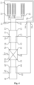
figures 1 to 6 , the air-conditioner includes a chassis (not marked in the figures), and the mainheat pump system 11 of the heat pump system in the above any solution is provided in the chassis. The workingmedium outlet 12 of the mainheat pump system 11 communicates with the workingmedium inlet 22 of the directly expanded strong cool-heat radiation plate 21 via a working medium feeding pipe, and the working medium feeding pipe extends through aninstallation port 32 of theroom 31. A workingmedium return intake 13 of the mainheat pump system 11 communicates with the workingmedium outlet 23 of the directly expanded strong cool-heat radiation plate 21 via a working medium return pipe, and the working medium return pipe extends through theinstallation port 33 of theroom 31. Theinstallation port 32 and theinstallation port 33 may be the same installation port. - Because the directly expanded strong cool-
heat radiation plate 21 and the mainheat pump system 11 are combined in the air-conditioner with the above heat pump system, the refrigerant in the mainheat pump system 11 exchanges heat via the directly expanded strong cool-heat radiation plate 21 directly, instead of secondary heat exchange of the refrigerant loop and the water circulation loop, thereby reducing loss in intermediate heat exchange, improving the heat exchange efficiency and heat utilization, and omitting the circulating pump for water circulation so as to lower energy consumption and simplify the installation. - The main heat pump system may undertake both sensible heat load (radiation heat transfer) and latent heat load (replacement air pre-cooled dehumidification or preheated humidification) in the
room 31. In order to further ensure the quality of the air and comfort in theroom 31, as shown infigure 3 , a replacement airheat pump system 61 is provided in the chassis of the air-conditioner. Areplacement air outlet 63 of the replacement airheat pump system 61 is adapted to be connected to thereplacement air intake 35 of theroom 31. If theroom 31 is kept in a good temperature condition, or the sensible heat load is low, the mainheat pump system 11 may be intermittently operated generally. In this case, when the mainheat pump system 11 is stopped, the replacement airheat pump system 61 in the embodiment of the present application may filter pre-cooled dehumidified replacement air or may preheat (humidify) the replacement air such as to meet the desired humidity and quality. - In order to reduce the energy consumption, as shown in
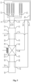
figure 4 , theair heat exchanger 51 is arranged between the mainheat pump system 11 and the replacement airheat pump system 61. A firstreplacement air outlet 53 of theair heat exchanger 51 is connected to areplacement air intake 64 of the replacement airheat pump system 61; a first return eduction air outlet 52 of theair heat exchanger 51 is connected to a heat sourceside air intake 65 of the replacement airheat pump system 61; the secondreplacement air outlet 55 of theair heat exchanger 51 is connected to thereplacement air intake 15 of the mainheat pump system 11; the second returneduction air outlet 54 of theair heat exchanger 51 is connected to the heat sourceside air intake 14 of the mainheat pump system 11; thereturn air intake 56 of theair heat exchanger 51 is connected to the returneduction air outlet 34 of theroom 31; and thereplacement air outlet 63 of the replacement airheat pump system 61 communicates with thereplacement air intake 35 of theroom 31. As shown infigures 5 to 6 in conjunction withfigure 4 , amultistage air filter 7 is provided at areplacement air intake 57 of theair heat exchanger 51 in order to improve the quality of the replacement air flowing into theroom 31. - As shown in
figure 6 , when the replacement airheat pump system 61 and the mainheat pump system 11 are both running, working medium in the mainheat pump system 11 flows through a working medium feeding pipe into the directly expanded strong cool-heat radiation plate 21 in theroom 31. The working medium is evaporated as a result of absorbing heat from theroom 31 so as to radiate cooling quantity (or condensed as a result of releasing heat into theroom 31 so as to radiate heating quantity), and then returns to the mainheat pump system 11 through a working medium discharging pipe. At the same time, outdoor fresh air flows into theair heat exchanger 51 via themultistage air filter 7, and makes primary heat exchange with the return air from theroom 31 so as to obtain primary pre-cooled (or pre-heated) and filtered replacement air, a part of which flows into the replacement airheat pump system 61, and the other part of which flows into the mainheat pump system 11 to be secondarily pre-cooled and dehumidified (or preheated and humidified) so as to form the replacement air which will be supplied into theroom 31. A part of return air undergoing primary heat recovery flows into a heat sourceside air intake 65 of the replacement airheat pump system 61, and the other part of the return air flows through a heat sourceside air intake 14 into the mainheat pump system 11, and is discharged from theeduction air outlet 16 of the mainheat pump system 11 and theeduction air outlet 62 of the replacement airheat pump system 61 after secondary full heat recovery is performed. - For the above air-conditioner, only the directly expanded strong cool-
heat radiation plate 21, thereplacement air intake 35, the returneduction air outlet 34, and thereturn air pipe 36 need to be arranged in theroom 31. The temperature in theroom 31 is uniform, without the blown feeling and the noise of the apparatus. In addition, with the replacement airheat pump system 61, the conditioned air in theroom 31 is fresh, has stable humidity and clean environment, thereby greatly improving the comfort in the room. Also, such an facility is easy to be installed, and may achieve a strong cooling radiation with a large temperature difference without moisture condensation, nor a strong heating radiation with a large temperature difference without dry and hot feeling, and may have a power of the facility reducing more than fifty percent than the conventional air-conditioner. The use of theair heat exchanger 51 enables an efficient full cool-heat recovery in the replacement air system, a simple structure, small volume, and a low cost.
| 11. | main | 12. | working |
| 13. | working | 14. | heat source |
| 15. | | 16. | |
| 17. | | ||
| 21. | directly expanded strong cool- | ||
| 22. | working | 23. | working |
| 31. | | 32. | |
| 33. | | 34. | return |
| 35. | | 36. | return |
| 40. | | 41. | building |
| 42. | | 43. | |
| 44. | | 45. | packed |
| 46. | | 47. | |
| 48. | | 49. | |
| 51. | air heat exchanger | 52. | first |
| 53. | first | 54. | second |
| 55. | second | 56. | return |
| 57. | | 61. | replacement air |
| 62. | | 63. | |
| 64. | | 65. | heat source |
| 7. | multistage air filter | ||
Claims (7)
- A heat pump system, comprising:a main heat pump system (11); anda directly expanded strong cool-heat radiation plate (21) provided on a building surface (41) and serving as the terminal of the main heat pump system (11);wherein the directly expanded strong cool-heat radiation plate (21) is configured to allow refrigerant in the main heat pump system (11) to circulate therein,wherein the directly expanded strong cool-heat radiation plate (21) comprises multiple pieces, the multiple pieces of the directly expanded strong cool-heat radiation plate (21) are interconnected in series or in parallel,wherein a heat retaining layer (47) and a reflecting layer are provided on the building surface (41), and wherein the reflecting layer is provided on an outside surface of the heat retaining layer (47) facing indoors, and the directly expanded strong cool-heat radiation plate (21) is fixed on the building surface (41) by means of a bracket (43),wherein a decorative face (42) is provided on a side of the directly expanded strong cool-heat radiation plate (21) exposed to the outside, a packed layer (45) with an enclosed cavity structure is located between the decorative face (42) and the directly expanded strong cool-heat radiation plate (21), the packed layer (45) has a cavity structure with an enclosed space defined by the decorative face (42), the directly expanded strong cool-heat radiation plate (21) and peripheral structures,characterized in thata buffer plate (46), which is used for weakening the transfer effect of cool or heat quantity from the directly expanded strong cool-heat radiation plate to a room, is further provided in the packed layer (45) between the decorative face (42) and the directly expanded strong cool-heat radiation plate (21).
- The heat pump system according to claim 1, wherein a protective condensation trough (49) for receiving condensed water is provided below the directly expanded strong cool-heat radiation plate (21), and is provided therein with a condensate outlet (40).
- An air-conditioner, comprising:a chassis, andthe heat pump system according to any one of claim 1 to 2;wherein the main heat pump system of the heat pump system is provided in the chassis.
- The air-conditioner according to claim 3, further comprising:
a replacement air heat pump system (61) provided in the chassis, wherein a replacement air outlet (63) of the replacement air heat pump system (61) is adapted to be connected to an replacement air intake (35) of a room (31). - The air-conditioner according to claim 4, wherein an air heat exchanger (51) is provided between the main heat pump system (11) and the replacement air heat pump system (61), and wherein a first replacement air outlet (53) of the air heat exchanger (51) is connected to a replacement air intake (64) of the replacement air heat pump system (61), a first return eduction air outlet (52) of the air heat exchanger (51) is connected to a heat source side air intake (65) of the replacement air heat pump system (61), a second replacement air outlet (55) of the air heat exchanger (51) is connected to a replacement air intake (15) of the main heat pump system (52), a second return eduction air outlet (55) of the air heat exchanger (51) is connected to a heat source side air intake (14) of the main heat pump system (11), a return air intake (56) of the air heat exchanger (51) is connected to a return eduction air outlet (34) of the room (31).
- The air-conditioner according to claim 5, wherein a multistage air filter (7) is provided at a replacement air intake (57) of the air heat exchanger (51).
- The air-conditioner according to claim 6, wherein the return air intake (56) of the air heat exchanger (51) is also connected to a return air pipe (36) arranged in the room (31).
Applications Claiming Priority (1)
| Application Number | Priority Date | Filing Date | Title |
|---|---|---|---|
| CN201310358748.4A CN103398507B (en) | 2013-08-16 | 2013-08-16 | A kind of heat pump and air conditioner |
Publications (4)
| Publication Number | Publication Date |
|---|---|
| EP2679922A2 EP2679922A2 (en) | 2014-01-01 |
| EP2679922A3 EP2679922A3 (en) | 2018-03-21 |
| EP2679922C0 EP2679922C0 (en) | 2023-06-07 |
| EP2679922B1 true EP2679922B1 (en) | 2023-06-07 |
Family
ID=49484141
Family Applications (1)
| Application Number | Title | Priority Date | Filing Date |
|---|---|---|---|
| EP13189788.6A Active EP2679922B1 (en) | 2013-08-16 | 2013-10-22 | Heat pump system and air-conditioner |
Country Status (7)
| Country | Link |
|---|---|
| US (1) | US20140090411A1 (en) |
| EP (1) | EP2679922B1 (en) |
| JP (1) | JP5868926B2 (en) |
| CN (1) | CN103398507B (en) |
| CA (1) | CA2829412C (en) |
| HK (1) | HK1190182A1 (en) |
| MY (1) | MY164250A (en) |
Families Citing this family (12)
| Publication number | Priority date | Publication date | Assignee | Title |
|---|---|---|---|---|
| CN103940019A (en) * | 2014-05-09 | 2014-07-23 | 广西钧富凰地源热泵有限公司 | Air conditioner system and heat pump equipment |
| DE102014109299A1 (en) * | 2014-07-03 | 2016-01-07 | Ferdinand Riedel | Hall tempering and hall with the Hallentemperieranordnung |
| WO2016044098A1 (en) | 2014-09-19 | 2016-03-24 | Ortner Charles R | Hvac home generator |
| CN104833023B (en) * | 2015-04-29 | 2017-12-15 | 西安宜新环境科技有限公司 | A kind of warm system of anion light spoke weighing apparatus |
| CN106051945A (en) * | 2016-07-11 | 2016-10-26 | 浙江理工大学 | Detachable turbine air purifier |
| CN106091198A (en) * | 2016-07-20 | 2016-11-09 | 重庆匠心通风技术有限公司 | Radiant panel changes in temperature integrated air regulation system |
| CN106403171B (en) * | 2016-09-10 | 2019-07-23 | 苏州暖舍节能科技有限公司 | A kind of radiation air-conditioner of quick acting |
| CN107036215B (en) * | 2017-06-07 | 2020-05-15 | 山东一村空调有限公司 | Intelligent dual-energy double-effect air conditioner |
| CN114076347B (en) * | 2020-08-17 | 2023-09-01 | 广东美的制冷设备有限公司 | Air conditioner, control method thereof and computer storage medium |
| CN111912068A (en) * | 2020-08-25 | 2020-11-10 | 无锡菲兰爱尔空气质量技术有限公司 | Radiation air conditioner terminal with asymmetric energy exchange |
| CN114183944A (en) * | 2020-09-15 | 2022-03-15 | 广州智得能源科技有限公司 | Energy-concerving and environment-protective type heat energy heat pump's heat cycle system and cold-proof device |
| CN112268314B (en) * | 2020-10-21 | 2022-03-08 | 扬州兆邦能源科技有限公司 | High-efficient heat transfer air conditioning unit |
Citations (3)
| Publication number | Priority date | Publication date | Assignee | Title |
|---|---|---|---|---|
| US6263690B1 (en) * | 1999-08-06 | 2001-07-24 | Barcol-Air Ag | Apparatus for cooling a room |
| JP2006214696A (en) * | 2005-02-07 | 2006-08-17 | Sanken Setsubi Kogyo Co Ltd | Air conditioner system |
| US20100198414A1 (en) * | 2007-06-28 | 2010-08-05 | Kroll Steven C | Systems and methods for controlling interior climates |
Family Cites Families (27)
| Publication number | Priority date | Publication date | Assignee | Title |
|---|---|---|---|---|
| GB1115642A (en) * | 1964-05-26 | 1968-05-29 | Eisler Paul | Space conditioning system |
| IS601B6 (en) * | 1963-10-23 | 1966-12-19 | Fordsmand Marc | Equipment for heating and cooling beds. |
| DE1454561B2 (en) * | 1964-03-05 | 1972-06-22 | Frenger International Corp , Bern | AIR CONDITIONING SYSTEM WITH A RADIANT UNDERCOVERING DESIGNED AS A VENTILATION SYSTEM |
| DE3047890A1 (en) * | 1980-12-19 | 1982-07-29 | Philips Patentverwaltung Gmbh, 2000 Hamburg | "DEVICE FOR VENTILATING AND HEATING INTERIORS" |
| US4938035A (en) * | 1987-10-20 | 1990-07-03 | Khanh Dinh | Regenerative fresh-air air conditioning system and method |
| JPH03518U (en) * | 1989-05-24 | 1991-01-07 | ||
| US5189884A (en) * | 1991-05-02 | 1993-03-02 | Sami Samuel M | Passive heat pump with non-azeotropic refrigerant |
| US5309732A (en) * | 1992-04-07 | 1994-05-10 | University Of Moncton | Combined cycle air/air heat pump |
| US5267450A (en) * | 1992-07-20 | 1993-12-07 | Matsushita Electric Ind. Co., Ltd. | Air conditioning apparatus |
| JPH0735367A (en) * | 1993-07-19 | 1995-02-07 | Daikin Plant Kk | Under-floor type air-conditioning device |
| JPH0972565A (en) * | 1995-09-06 | 1997-03-18 | Hitachi Ltd | Indoor machine of radiation type air conditioner |
| JPH09329342A (en) * | 1996-06-07 | 1997-12-22 | Mitsubishi Electric Corp | Radiation air conditioner |
| US6923248B1 (en) * | 1996-09-11 | 2005-08-02 | Reiner Weber | Cooling cover, cooling cover components and cooling tubular armature |
| US5931381A (en) * | 1997-05-23 | 1999-08-03 | Fiedrich; Joachim | For radiant floor, wall and ceiling hydronic heating and/or cooling systems using metal plates that are heated or cooled by attached tubing that is fed hot or cold water, techniques of improving performance and avoiding condensation when cooling |
| ATE334355T1 (en) * | 2003-12-08 | 2006-08-15 | Barcol Air | COOLING ELEMENT AND COOLING DEVICE AND METHOD FOR OPERATING THEM |
| CN1279318C (en) * | 2004-03-04 | 2006-10-11 | 上海交通大学 | Displacement ventilation radiator |
| JP4922603B2 (en) * | 2004-11-30 | 2012-04-25 | 昭和電工株式会社 | Radiant panel |
| KR100638223B1 (en) * | 2005-06-16 | 2006-10-27 | 엘지전자 주식회사 | Electric generation air condition system |
| JP2006194080A (en) * | 2006-03-17 | 2006-07-27 | Inter Central:Kk | Double floor structure for air-conditioning and heating equipment and floor blow-off air conditioning/heating and cooling device |
| JP4750058B2 (en) * | 2007-02-27 | 2011-08-17 | 正 角田 | Operating room |
| US7802443B2 (en) * | 2007-04-13 | 2010-09-28 | Air Innovations, Inc. | Total room air purification system with air conditioning, filtration and ventilation |
| CN201191049Y (en) * | 2008-04-10 | 2009-02-04 | 西安工程大学 | Radiation air conditioning system based on recycling wet cooling tower and cold/heat sources of ground source heat pump |
| JP2012026700A (en) * | 2010-07-27 | 2012-02-09 | Mitsubishi Heavy Ind Ltd | Desiccant air-conditioning system |
| JP5131359B2 (en) * | 2011-01-19 | 2013-01-30 | ダイキン工業株式会社 | Air conditioner |
| WO2013026206A1 (en) * | 2011-08-25 | 2013-02-28 | Feng Zhengyi | Building built-in air conditioner |
| JP5869955B2 (en) * | 2012-05-23 | 2016-02-24 | シャープ株式会社 | Radiant air conditioner |
| CN203478700U (en) * | 2013-08-16 | 2014-03-12 | 广西钧富凰地源热泵有限公司 | Heat pump system and air conditioner |
-
2013
- 2013-08-16 CN CN201310358748.4A patent/CN103398507B/en active Active
- 2013-10-03 CA CA2829412A patent/CA2829412C/en active Active
- 2013-10-22 EP EP13189788.6A patent/EP2679922B1/en active Active
- 2013-10-30 MY MYPI2013003956A patent/MY164250A/en unknown
- 2013-10-30 US US14/066,703 patent/US20140090411A1/en not_active Abandoned
- 2013-10-31 JP JP2013227093A patent/JP5868926B2/en active Active
-
2014
- 2014-04-04 HK HK14103265.6A patent/HK1190182A1/en unknown
Patent Citations (3)
| Publication number | Priority date | Publication date | Assignee | Title |
|---|---|---|---|---|
| US6263690B1 (en) * | 1999-08-06 | 2001-07-24 | Barcol-Air Ag | Apparatus for cooling a room |
| JP2006214696A (en) * | 2005-02-07 | 2006-08-17 | Sanken Setsubi Kogyo Co Ltd | Air conditioner system |
| US20100198414A1 (en) * | 2007-06-28 | 2010-08-05 | Kroll Steven C | Systems and methods for controlling interior climates |
Also Published As
| Publication number | Publication date |
|---|---|
| CN103398507B (en) | 2016-01-27 |
| MY164250A (en) | 2017-11-30 |
| HK1190182A1 (en) | 2014-06-27 |
| CA2829412C (en) | 2017-09-19 |
| EP2679922C0 (en) | 2023-06-07 |
| JP5868926B2 (en) | 2016-02-24 |
| US20140090411A1 (en) | 2014-04-03 |
| EP2679922A2 (en) | 2014-01-01 |
| EP2679922A3 (en) | 2018-03-21 |
| CA2829412A1 (en) | 2013-12-19 |
| CN103398507A (en) | 2013-11-20 |
| JP2014052182A (en) | 2014-03-20 |
Similar Documents
| Publication | Publication Date | Title |
|---|---|---|
| EP2679922B1 (en) | Heat pump system and air-conditioner | |
| JP5076745B2 (en) | Ventilation air conditioner | |
| JP5043158B2 (en) | Air source heat pump air conditioner | |
| US10663198B2 (en) | Heat pump system and air-conditioner | |
| JP5967581B2 (en) | Air conditioner | |
| JP2016217630A (en) | Radiation air-conditioning system | |
| CN104913413A (en) | Integrated energy-saving building heating/cooling system by efficient air circulation technology | |
| JP5285179B1 (en) | Air conditioner | |
| JP2009250528A (en) | Ventilation air-conditioning device | |
| CN113188205A (en) | Airflow-prevention tissue cross heat exchange system with cold and heat radiation plates | |
| JP5913151B2 (en) | Air conditioning and ventilation system | |
| CN209819742U (en) | Variable-frequency multi-connected radiation heating and refrigerating air conditioning system | |
| JP4605759B2 (en) | Indoor air conditioning system for buildings | |
| JP4698204B2 (en) | Indoor air conditioning system for buildings | |
| KR200439886Y1 (en) | Floor Radiation with Convection Cooling Heating and Ventilation System | |
| US9273874B2 (en) | Air conditioning and venting system | |
| CN203478700U (en) | Heat pump system and air conditioner | |
| JP3818379B2 (en) | Recessed floor air conditioner | |
| JPH02103324A (en) | Air conditioning system designed for intelligent building | |
| CN216203917U (en) | Radiant panel group for indoor heat exchange and office station air conditioning system | |
| CN216281801U (en) | Airflow-prevention tissue cross heat exchange system with cold and heat radiation plates | |
| CN107894027B (en) | Radiation air conditioner | |
| JP2003240252A (en) | Water (water cooling) air conditioner and floor heating by hp hot water feeding | |
| JPH049530A (en) | Cooling device mountable on ceiling | |
| TWM477554U (en) | Integration system of window type air-conditioner and heat exchange device |
Legal Events
| Date | Code | Title | Description |
|---|---|---|---|
| PUAI | Public reference made under article 153(3) epc to a published international application that has entered the european phase |
Free format text: ORIGINAL CODE: 0009012 |
|
| 17P | Request for examination filed |
Effective date: 20131022 |
|
| AK | Designated contracting states |
Kind code of ref document: A2 Designated state(s): AL AT BE BG CH CY CZ DE DK EE ES FI FR GB GR HR HU IE IS IT LI LT LU LV MC MK MT NL NO PL PT RO RS SE SI SK SM TR |
|
| AX | Request for extension of the european patent |
Extension state: BA ME |
|
| PUAL | Search report despatched |
Free format text: ORIGINAL CODE: 0009013 |
|
| AK | Designated contracting states |
Kind code of ref document: A3 Designated state(s): AL AT BE BG CH CY CZ DE DK EE ES FI FR GB GR HR HU IE IS IT LI LT LU LV MC MK MT NL NO PL PT RO RS SE SI SK SM TR |
|
| AX | Request for extension of the european patent |
Extension state: BA ME |
|
| RIC1 | Information provided on ipc code assigned before grant |
Ipc: F24F 12/00 20060101ALI20180212BHEP Ipc: F25B 30/00 20060101ALI20180212BHEP Ipc: F24F 13/22 20060101ALI20180212BHEP Ipc: F24F 5/00 20060101ALI20180212BHEP Ipc: F24F 3/00 20060101AFI20180212BHEP Ipc: F24F 1/00 20110101ALI20180212BHEP |
|
| STAA | Information on the status of an ep patent application or granted ep patent |
Free format text: STATUS: REQUEST FOR EXAMINATION WAS MADE |
|
| RAP1 | Party data changed (applicant data changed or rights of an application transferred) |
Owner name: GUANGXI JUNFUHUANG GROUND SOURCE HEAT PUMP CO., LT Owner name: GUANGXI UNIVERSITY |
|
| RBV | Designated contracting states (corrected) |
Designated state(s): AL AT BE BG CH CY CZ DE DK EE ES FI FR GB GR HR HU IE IS IT LI LT LU LV MC MK MT NL NO PL PT RO RS SE SI SK SM TR |
|
| STAA | Information on the status of an ep patent application or granted ep patent |
Free format text: STATUS: EXAMINATION IS IN PROGRESS |
|
| 17Q | First examination report despatched |
Effective date: 20190801 |
|
| STAA | Information on the status of an ep patent application or granted ep patent |
Free format text: STATUS: EXAMINATION IS IN PROGRESS |
|
| STAA | Information on the status of an ep patent application or granted ep patent |
Free format text: STATUS: EXAMINATION IS IN PROGRESS |
|
| RIN1 | Information on inventor provided before grant (corrected) |
Inventor name: HU, YINGNING Inventor name: QIN, WENQI Inventor name: WANG, YAN Inventor name: LEI, JUN |
|
| RAP3 | Party data changed (applicant data changed or rights of an application transferred) |
Owner name: GUANGXI UNIVERSITY Owner name: GUANGXI JUNFUHUANG BUILDING ENVIRONMENT TECHNOLOGY CO., LTD. |
|
| RAP3 | Party data changed (applicant data changed or rights of an application transferred) |
Owner name: GUANGXI JUNFUHUANG BUILDING ENVIRONMENT TECHNOLOGY CO., LTD. Owner name: GUANGXI UNIVERSITY |
|
| RIC1 | Information provided on ipc code assigned before grant |
Ipc: F24F 12/00 20060101ALI20221013BHEP Ipc: F24F 13/22 20060101ALI20221013BHEP Ipc: F24F 1/0059 20190101ALI20221013BHEP Ipc: F24F 1/0007 20190101ALI20221013BHEP Ipc: F24F 5/00 20060101ALI20221013BHEP Ipc: F25B 30/00 20060101ALI20221013BHEP Ipc: F24F 3/00 20060101AFI20221013BHEP |
|
| GRAP | Despatch of communication of intention to grant a patent |
Free format text: ORIGINAL CODE: EPIDOSNIGR1 |
|
| STAA | Information on the status of an ep patent application or granted ep patent |
Free format text: STATUS: GRANT OF PATENT IS INTENDED |
|
| INTG | Intention to grant announced |
Effective date: 20221215 |
|
| GRAS | Grant fee paid |
Free format text: ORIGINAL CODE: EPIDOSNIGR3 |
|
| GRAA | (expected) grant |
Free format text: ORIGINAL CODE: 0009210 |
|
| STAA | Information on the status of an ep patent application or granted ep patent |
Free format text: STATUS: THE PATENT HAS BEEN GRANTED |
|
| AK | Designated contracting states |
Kind code of ref document: B1 Designated state(s): AL AT BE BG CH CY CZ DE DK EE ES FI FR GB GR HR HU IE IS IT LI LT LU LV MC MK MT NL NO PL PT RO RS SE SI SK SM TR |
|
| REG | Reference to a national code |
Ref country code: GB Ref legal event code: FG4D |
|
| REG | Reference to a national code |
Ref country code: CH Ref legal event code: EP Ref country code: AT Ref legal event code: REF Ref document number: 1576163 Country of ref document: AT Kind code of ref document: T Effective date: 20230615 |
|
| REG | Reference to a national code |
Ref country code: DE Ref legal event code: R096 Ref document number: 602013083891 Country of ref document: DE |
|
| U01 | Request for unitary effect filed |
Effective date: 20230607 |
|
| U07 | Unitary effect registered |
Designated state(s): AT BE BG DE DK EE FI FR IT LT LU LV MT NL PT SE SI Effective date: 20230629 |
|
| REG | Reference to a national code |
Ref country code: LT Ref legal event code: MG9D |
|
| PG25 | Lapsed in a contracting state [announced via postgrant information from national office to epo] |
Ref country code: NO Free format text: LAPSE BECAUSE OF FAILURE TO SUBMIT A TRANSLATION OF THE DESCRIPTION OR TO PAY THE FEE WITHIN THE PRESCRIBED TIME-LIMIT Effective date: 20230907 Ref country code: ES Free format text: LAPSE BECAUSE OF FAILURE TO SUBMIT A TRANSLATION OF THE DESCRIPTION OR TO PAY THE FEE WITHIN THE PRESCRIBED TIME-LIMIT Effective date: 20230607 |
|
| PG25 | Lapsed in a contracting state [announced via postgrant information from national office to epo] |
Ref country code: RS Free format text: LAPSE BECAUSE OF FAILURE TO SUBMIT A TRANSLATION OF THE DESCRIPTION OR TO PAY THE FEE WITHIN THE PRESCRIBED TIME-LIMIT Effective date: 20230607 Ref country code: HR Free format text: LAPSE BECAUSE OF FAILURE TO SUBMIT A TRANSLATION OF THE DESCRIPTION OR TO PAY THE FEE WITHIN THE PRESCRIBED TIME-LIMIT Effective date: 20230607 Ref country code: GR Free format text: LAPSE BECAUSE OF FAILURE TO SUBMIT A TRANSLATION OF THE DESCRIPTION OR TO PAY THE FEE WITHIN THE PRESCRIBED TIME-LIMIT Effective date: 20230908 |
|
| PG25 | Lapsed in a contracting state [announced via postgrant information from national office to epo] |
Ref country code: SK Free format text: LAPSE BECAUSE OF FAILURE TO SUBMIT A TRANSLATION OF THE DESCRIPTION OR TO PAY THE FEE WITHIN THE PRESCRIBED TIME-LIMIT Effective date: 20230607 |
|
| PG25 | Lapsed in a contracting state [announced via postgrant information from national office to epo] |
Ref country code: IS Free format text: LAPSE BECAUSE OF FAILURE TO SUBMIT A TRANSLATION OF THE DESCRIPTION OR TO PAY THE FEE WITHIN THE PRESCRIBED TIME-LIMIT Effective date: 20231007 |
|
| PG25 | Lapsed in a contracting state [announced via postgrant information from national office to epo] |
Ref country code: SM Free format text: LAPSE BECAUSE OF FAILURE TO SUBMIT A TRANSLATION OF THE DESCRIPTION OR TO PAY THE FEE WITHIN THE PRESCRIBED TIME-LIMIT Effective date: 20230607 Ref country code: SK Free format text: LAPSE BECAUSE OF FAILURE TO SUBMIT A TRANSLATION OF THE DESCRIPTION OR TO PAY THE FEE WITHIN THE PRESCRIBED TIME-LIMIT Effective date: 20230607 Ref country code: RO Free format text: LAPSE BECAUSE OF FAILURE TO SUBMIT A TRANSLATION OF THE DESCRIPTION OR TO PAY THE FEE WITHIN THE PRESCRIBED TIME-LIMIT Effective date: 20230607 Ref country code: IS Free format text: LAPSE BECAUSE OF FAILURE TO SUBMIT A TRANSLATION OF THE DESCRIPTION OR TO PAY THE FEE WITHIN THE PRESCRIBED TIME-LIMIT Effective date: 20231007 Ref country code: CZ Free format text: LAPSE BECAUSE OF FAILURE TO SUBMIT A TRANSLATION OF THE DESCRIPTION OR TO PAY THE FEE WITHIN THE PRESCRIBED TIME-LIMIT Effective date: 20230607 |
|
| U21 | Renewal fee paid with penalty [unitary effect] |
Year of fee payment: 11 Effective date: 20231123 |
|
| PG25 | Lapsed in a contracting state [announced via postgrant information from national office to epo] |
Ref country code: PL Free format text: LAPSE BECAUSE OF FAILURE TO SUBMIT A TRANSLATION OF THE DESCRIPTION OR TO PAY THE FEE WITHIN THE PRESCRIBED TIME-LIMIT Effective date: 20230607 |
|
| REG | Reference to a national code |
Ref country code: DE Ref legal event code: R097 Ref document number: 602013083891 Country of ref document: DE |
|
| PLBE | No opposition filed within time limit |
Free format text: ORIGINAL CODE: 0009261 |
|
| STAA | Information on the status of an ep patent application or granted ep patent |
Free format text: STATUS: NO OPPOSITION FILED WITHIN TIME LIMIT |