EP2374548B1 - Cylindrical sieve and cylindrical sifter - Google Patents
Cylindrical sieve and cylindrical sifter Download PDFInfo
- Publication number
- EP2374548B1 EP2374548B1 EP10783124.0A EP10783124A EP2374548B1 EP 2374548 B1 EP2374548 B1 EP 2374548B1 EP 10783124 A EP10783124 A EP 10783124A EP 2374548 B1 EP2374548 B1 EP 2374548B1
- Authority
- EP
- European Patent Office
- Prior art keywords
- sieve
- cylindrical
- granular material
- sifter
- sieve body
- Prior art date
- Legal status (The legal status is an assumption and is not a legal conclusion. Google has not performed a legal analysis and makes no representation as to the accuracy of the status listed.)
- Active
Links
- 239000008187 granular material Substances 0.000 claims description 108
- 238000003756 stirring Methods 0.000 claims description 50
- 238000007873 sieving Methods 0.000 description 58
- 238000007689 inspection Methods 0.000 description 13
- 230000000694 effects Effects 0.000 description 12
- 238000000034 method Methods 0.000 description 11
- 230000006378 damage Effects 0.000 description 10
- 239000000463 material Substances 0.000 description 9
- 238000005336 cracking Methods 0.000 description 7
- 230000001965 increasing effect Effects 0.000 description 5
- 230000033001 locomotion Effects 0.000 description 5
- 239000002184 metal Substances 0.000 description 5
- 229910052751 metal Inorganic materials 0.000 description 5
- 230000007423 decrease Effects 0.000 description 3
- 230000004048 modification Effects 0.000 description 3
- 238000012986 modification Methods 0.000 description 3
- 239000000843 powder Substances 0.000 description 3
- XEEYBQQBJWHFJM-UHFFFAOYSA-N Iron Chemical compound [Fe] XEEYBQQBJWHFJM-UHFFFAOYSA-N 0.000 description 2
- 230000002730 additional effect Effects 0.000 description 2
- 230000015572 biosynthetic process Effects 0.000 description 2
- 238000005345 coagulation Methods 0.000 description 2
- 230000015271 coagulation Effects 0.000 description 2
- 235000013305 food Nutrition 0.000 description 2
- 230000005484 gravity Effects 0.000 description 2
- 230000004807 localization Effects 0.000 description 2
- 239000013618 particulate matter Substances 0.000 description 2
- 239000011148 porous material Substances 0.000 description 2
- 238000012216 screening Methods 0.000 description 2
- 238000007789 sealing Methods 0.000 description 2
- XLYOFNOQVPJJNP-UHFFFAOYSA-N water Substances O XLYOFNOQVPJJNP-UHFFFAOYSA-N 0.000 description 2
- 238000003466 welding Methods 0.000 description 2
- 230000004075 alteration Effects 0.000 description 1
- 230000004323 axial length Effects 0.000 description 1
- 239000000919 ceramic Substances 0.000 description 1
- 229910010293 ceramic material Inorganic materials 0.000 description 1
- 238000004140 cleaning Methods 0.000 description 1
- 230000001112 coagulating effect Effects 0.000 description 1
- 239000006185 dispersion Substances 0.000 description 1
- 238000009826 distribution Methods 0.000 description 1
- 238000011143 downstream manufacturing Methods 0.000 description 1
- 230000002708 enhancing effect Effects 0.000 description 1
- 238000001125 extrusion Methods 0.000 description 1
- 235000008446 instant noodles Nutrition 0.000 description 1
- 230000002452 interceptive effect Effects 0.000 description 1
- 229910052742 iron Inorganic materials 0.000 description 1
- 239000007788 liquid Substances 0.000 description 1
- 239000007769 metal material Substances 0.000 description 1
- 238000005065 mining Methods 0.000 description 1
- 238000005192 partition Methods 0.000 description 1
- 239000004033 plastic Substances 0.000 description 1
- 239000002985 plastic film Substances 0.000 description 1
- 238000004080 punching Methods 0.000 description 1
- 238000010926 purge Methods 0.000 description 1
- 238000011084 recovery Methods 0.000 description 1
- 230000009467 reduction Effects 0.000 description 1
- 238000000926 separation method Methods 0.000 description 1
- 235000014347 soups Nutrition 0.000 description 1
- 229910001220 stainless steel Inorganic materials 0.000 description 1
- 239000010935 stainless steel Substances 0.000 description 1
- 239000000126 substance Substances 0.000 description 1
- 238000011144 upstream manufacturing Methods 0.000 description 1
- 238000005406 washing Methods 0.000 description 1
Images


Classifications
-
- B—PERFORMING OPERATIONS; TRANSPORTING
- B07—SEPARATING SOLIDS FROM SOLIDS; SORTING
- B07B—SEPARATING SOLIDS FROM SOLIDS BY SIEVING, SCREENING, SIFTING OR BY USING GAS CURRENTS; SEPARATING BY OTHER DRY METHODS APPLICABLE TO BULK MATERIAL, e.g. LOOSE ARTICLES FIT TO BE HANDLED LIKE BULK MATERIAL
- B07B1/00—Sieving, screening, sifting, or sorting solid materials using networks, gratings, grids, or the like
- B07B1/18—Drum screens
- B07B1/22—Revolving drums
- B07B1/24—Revolving drums with fixed or moving interior agitators
-
- B—PERFORMING OPERATIONS; TRANSPORTING
- B07—SEPARATING SOLIDS FROM SOLIDS; SORTING
- B07B—SEPARATING SOLIDS FROM SOLIDS BY SIEVING, SCREENING, SIFTING OR BY USING GAS CURRENTS; SEPARATING BY OTHER DRY METHODS APPLICABLE TO BULK MATERIAL, e.g. LOOSE ARTICLES FIT TO BE HANDLED LIKE BULK MATERIAL
- B07B1/00—Sieving, screening, sifting, or sorting solid materials using networks, gratings, grids, or the like
- B07B1/46—Constructional details of screens in general; Cleaning or heating of screens
- B07B1/4609—Constructional details of screens in general; Cleaning or heating of screens constructional details of screening surfaces or meshes
- B07B1/4654—Corrugated Screening surfaces
-
- B—PERFORMING OPERATIONS; TRANSPORTING
- B07—SEPARATING SOLIDS FROM SOLIDS; SORTING
- B07B—SEPARATING SOLIDS FROM SOLIDS BY SIEVING, SCREENING, SIFTING OR BY USING GAS CURRENTS; SEPARATING BY OTHER DRY METHODS APPLICABLE TO BULK MATERIAL, e.g. LOOSE ARTICLES FIT TO BE HANDLED LIKE BULK MATERIAL
- B07B1/00—Sieving, screening, sifting, or sorting solid materials using networks, gratings, grids, or the like
- B07B1/46—Constructional details of screens in general; Cleaning or heating of screens
- B07B1/4609—Constructional details of screens in general; Cleaning or heating of screens constructional details of screening surfaces or meshes
- B07B1/469—Perforated sheet-like material
-
- B—PERFORMING OPERATIONS; TRANSPORTING
- B07—SEPARATING SOLIDS FROM SOLIDS; SORTING
- B07B—SEPARATING SOLIDS FROM SOLIDS BY SIEVING, SCREENING, SIFTING OR BY USING GAS CURRENTS; SEPARATING BY OTHER DRY METHODS APPLICABLE TO BULK MATERIAL, e.g. LOOSE ARTICLES FIT TO BE HANDLED LIKE BULK MATERIAL
- B07B13/00—Grading or sorting solid materials by dry methods, not otherwise provided for; Sorting articles otherwise than by indirectly controlled devices
- B07B13/14—Details or accessories
- B07B13/16—Feed or discharge arrangements
Definitions
- the present invention relates to a cylindrical sieve and a cylindrical sifter, and more specifically to a technique of sieving various granular materials and powdery materials with the cylindrical sieve.
- a conventionally known cylindrical sieve generally includes a cylindrical sieve screen having square meshes as shown in Patent Literatures 1 and 2, rectangular meshes as shown in Patent Literature 3, or special polygonal meshes according to the applications as shown in Patent Literature 4.
- Sieving the granular material accordingly has the problem of difficulty in passage through the screen and the problem of the lowered commercial value due to the potential destruction or cracking of the grains stuck between the screen and a stirring member rotating in the screen.
- the effective measure to solve such problems is thus highly demanded.
- Using a stirring member is not preferable since the granular material may be damaged (destroyed or cracked) by the contact with the stirring member.
- a portable mining apparatus is described with a self-contained revolving trommel classifying and sluice type recovery plant.
- the trommel screen is perforated and provided with helical corrugations to subject received placer material to several forces which, combined with sufficient water added through provided nozzles, break up the placer material and expose values to the trommel perforations.
- the perforations are arranged in a continuous pattern within the length of the trommel. Classified material drops through the perforations into an elongated sluice, along with all the accumulated water used in the classifying-washing process. Values are separated from tailings by corrugations along the sluice length.
- a suction pump operates with a suction hose and settling tank to recover values from the sluice during operation.
- DE 20214115 U1 describes a rotating drum having perforated helical profile and interlocking profiled brush separating one grade of particulate matter from a larger grade.
- a horizontal rotating perforated-drum sieves small dry particulate matter from coarser matter on a large scale.
- the drum has a helical profile which engages as it rotates with a matching brush also with a helical profile.
- JP 10 328505 A a concentration type coagulation reactor is described.
- the concentration type coagulating reactor capable of performing the coagulation and separation/concentration of a liquid to be treated by a single device and in which a concentrating screen is arranged
- the concentrating screen is made into a corrugated cylinder type and the direction of the slit mesh of the screen is made to the horizontal direction.
- the diameter of bristles of a brush is made smaller than the aperture of the slit mesh, the end of bristles of the brush is passed through the slit mesh and the length of the bristles of the brush is made so as to be brought barely into contact with the support wire of the screen.
- the brush rotates relative to the screen while it is brought into contact with the slit surface to remove the coagulated products.
- one aspect of the invention is directed to a cylindrical sieve including a cylindrical sieve body (4) made from a corrugated plate having wave crests formed along an axial direction of the cylindrical sieve (1) and wave troughs formed along the axial direction of the cylindrical sieve (1), said wave crests and said troughs being arranged alternately along its circumference of the cylindrical sieve (1), wherein a large number of apertures (5) with a longitudinal axis aligned in the axial direction of the cylindrical sieve (1) are formed in the corrugated plate, and said apertures (5) are formed on all sides of said wave crests, wave troughs and planar inclined areas on the boundaries between the wave crests and wave troughs.
- One preferable application of the invention is a cylindrical sifter (10) including a rotating shaft (2) and a support member (3) extended radially from outer circumference of the rotating shaft (2).
- the sieve body (4) is fastened to outer circumference of the support member (3) and causes sieved granular material to pass from an inner region (25) of the sieve body (4) to an outer region (26).
- Another preferable application of the invention is another cylindrical sifter (200) including a rotating shaft (207a), a stirring member (207) extended radially from outer circumference of the rotating shaft (207a) to stir granular material, and a cylindrical sieve body (204) spaced apart from the stirring member (207) and fastened to a sieve housing.
- the stirring member (207) is rotated in the sieve body (204) and causes sieved granular material to pass from an inner region of the sieve body (204) to an outer region.
- the corrugated plate is preferably a punching sheet, such as a metal sheet, a ceramic sheet, or a plastic sheet with a plurality of apertures formed therein.
- a screen net may also be employed for the corrugated plate.
- each of the apertures (5) is formed as an oval shape.
- the sieve body (4) having a plurality of oval apertures (5) enables easy passage of cylindrical grains through the apertures (5) and has the enhanced sieving efficiency.
- the plurality of apertures (5) are formed in the corrugated plate, such that the longitudinal axis of each of the apertures (5) is aligned in a preset direction.
- the preset direction is a direction parallel to the axial direction of the rotating shaft (2) of the sieve body (4).
- one array of the apertures (5) is shifted in position in the axial direction from an adjacent array of the apertures (5).
- the cylindrical sifter may be an inline sifter or a non-inline sifter.
- the structure of the present invention is especially suitable for a sieve horizontally arranged in the sifter but may also be applicable to a sieve vertically arranged in the sifter.
- Another none claimed aspect of the invention is directed to a double cylindrical sifter (100) including an upper or first-stage cylindrical sifter (110) and a lower or second-stage cylindrical sifter (150), where the upper cylindrical sifter (110) has a greater pore size of sieve apertures (115) than the pore size of sieve apertures (155) of the lower cylindrical sifter (150).
- the sieved granular material through the upper or first-stage cylindrical sifter (110) may be fed by a volumetric feeder (1116) into a granular material inlet (1511) of the lower or second-stage cylindrical sifter (150).
- the cylindrical sieve and the cylindrical sifter of the present invention are not restrictively used for sieving granular materials but may also be used for sieving various powdery materials.
- corrugated plate for the sieve body increases the sieving area and generates the lifting-up force of the granular material, thus enhancing the sieving efficiency.
- the formation of the large number of apertures in the corrugated plate helps alignment of direction of the grains and facilitates passage of the grains through the apertures, thus further increasing the sieving efficiency.
- the corrugated sieve body In the structure of the sieve body rotating with the support member, there is substantially no possibility that the granular material is stuck between the support member and the sieve body. This arrangement prevents potential destruction and cracking of various granular materials, such as cylindrical grains, and enhances the commercial value of the sieved granular material.
- the corrugated plate In the structure of the corrugated sieve body with the stirring member rotating therein, the corrugated plate makes a space between the stirring member and the sieve body for receiving the grains. This arrangement lowers the potential for destruction of the granular material.
- a cylindrical sieve 1 according to the invention and a cylindrical sifter 10 according to one embodiment of the present invention are discussed below with reference to Figs. 1 through 7 .
- the cylindrical sieve 1 has a rotating shaft 2, support members 3, a sieve body 4, and sieve frames 6a and 6b.
- the cylindrical sieve 1 is integrally rotated around the rotating shaft 2 with a driveshaft 21 ( Fig. 5 ) inserted therein.
- the respective parts of the cylindrical sieve 1 are described in detail below.
- the rotating shaft 2 is a cylindrical member extended in the axial direction and arranged on the center of the cylindrical sieve 1 and serves as a rotational center of the sieve body 4.
- Each of the support members 3 is located between the outer periphery of the rotating shaft 2 and the sieve body 4 and is radially extended inside the sieve body 4.
- the sieve body 4 is connected to the rotating shaft 2 by the support members 3 to be rotated integrally with the rotating shaft 2.
- the cylindrical sieve 1 is fixed by inserting the driveshaft 21 into the rotating shaft 2. The method of such fixation will be described later.
- each of the support members 3 is extended radially from the rotating shaft 2 to be linked with the sieve body 4 to transmit the rotating force of the rotating shaft 2 to the sieve body 4.
- each of the support members 3 has a plurality of (four in the illustrated embodiment) plate arms 3a extended radially (four different directions at intervals of 90 degrees in the illustrated embodiment, but may be in any other suitable arrangement, for example, in three different directions at intervals of 120 degrees) from the rotating shaft 2, an inner ring 3b provided to connect the respective base ends of the plate arms 3a to the outer periphery of the rotating shaft 2, and an outer ring 3c provided along the inner circumference of the sieve body 4 to be connected to the respective extended ends of the plate arms 3a.
- the outer ring 3c is concaved in specific portions on the outer circumference interfering with respective wave troughs of the corrugated sieve body 4.
- the plate arms 3a, the inner ring 3b, and the outer ring 3c are made integrally from a plate member having the thickness direction parallel to the axial direction of the rotating shaft 2.
- a plurality of (two in the illustrated embodiment) the support members 3 are arranged at a preset interval in the axial direction to support the sieve body 4.
- the plate arms 3a are radially extended at equal intervals. This arrangement is, however, neither essential nor restrictive.
- the plate arms 3a may be spirally extended from the rotating shaft 2 to the sieve body 4.
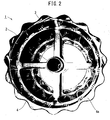
- the sieve body 4 is a cylindrical corrugated plate having wave crests and wave troughs arranged along its circumference and has a large number of apertures 5 formed in the corrugated plate.
- the sieve body 4 is linked with the support members 3 to receive the rotating force transmitted from the rotating shaft 2.
- the sieve body 4 is formed in a regular corrugated shape having wave crests and wave troughs, which are regularly and alternately arranged along its circumference and continue in its axial direction, and substantially planar inclined areas on the boundaries between the wave crests and the wave troughs.
- the wave crests are combined with the concaved portions on the outer circumference of the outer ring 3c by welding or by any other suitable technique.
- the sieve body 4 is made from a metal plate, for example, a stainless steel plate or another iron plate and preferably has rigidity and elasticity, however, may have flexibility.
- One preferable method of providing the cylindrical sieve body 4 rings a corrugated metal plate with a large number of apertures 5 and welds the facing ends together to form the cylindrical sieve body 4.
- each of the apertures 5 is formed in an oval shape as shown in Figs. 1 and 3 .
- the respective apertures 5 are preferably formed in an identical shape and in identical dimensions.
- the apertures 5 may be formed, for example, by perforation in the metal plate.
- the apertures 5 are formed evenly over the sieve body 4, except two axial ends of the sieve body 4 to which the sieve frames 6a and 6b are fastened for the strength requirement.
- the horizontal to vertical ratio of the apertures 5 is preferably in a range of 2:1 to 10:1.
- the sieve body 4 has an aperture ratio of 30 to 60%.
- each of the apertures 5 has the vertical dimension of 3 to 3.4 mm and the horizontal dimension of 10 to 12 mm.
- the distance between the central axes of the adjacent apertures 5 is 4 to 8 mm in the vertical direction and 13 to 15 mm in the horizontal direction.
- the metal plate of the sieve body 4 has the thickness of 0.5 to 1.5 mm.
- the apertures 5 are arranged such that the longitudinal axes of the respective oval apertures 5 are arrayed in the axial direction of the rotating shaft 2.
- One array 5A of the apertures 5 is shifted in position in the axial direction from an adjacent array 5B of the apertures 5 ( Fig. 3 ).
- the sieve frames 6a and 6b are ring-shaped plate members having the outer circumference conforming with the corrugated shape of the sieve body 4.
- the sieve frames 6a and 6b are mounted on the respective axial ends of the cylindrical sieve body 4.
- the sieve frames 6a and 6b have the thickness direction parallel to the axial direction of the rotating shaft 2.
- the sieve frames 6a and 6b may additionally be mounted in the middle of the axial length of the sieve body 4, in addition to the axial ends of the sieve body 4.
- the sieve frames 6a and 6b may have the smooth ring-shaped outer circumference, instead of the outer circumference conforming with the corrugated shape of the sieve body 4.
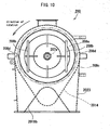
- the cylindrical sifter 10 has a granular material inlet 11, a supply casing 19, a sieve housing 23, a granular material outlet 14a, a non-sieved outlet 18c, and an inspection door 13.
- the cylindrical sieve 1 described above is located in the sieve housing 23. The respective parts of the cylindrical sifter 10 are discussed below.
- the granular material inlet 11 is a round tube to receive grains or granular material supplied from an upstream line via a rotary valve or another valve (not shown).
- the granular material inlet 11 is connected with the supply casing 19.
- the supply casing 19 includes a cylindrical supply chamber 20.
- the supply chamber 20 communicates with the granular material inlet 11 and a sieving chamber 24.
- the supply chamber 20 has a smaller capacity than the capacity of the sieving chamber 24.
- the sieve housing 23 is arranged to cover over most of the cylindrical sifter 10.
- the inside of the sieve housing 23 is roughly divided into three sections, a sieving section 12, a sieved outlet section 14, and a non-sieved outlet section 18.
- the non-sieved outlet 18c is provided in the downstream of the sieved outlet section 14 to discharge the non-sieved granular material from the cylindrical sifter 10.
- the inspection door 13 is attached to a right side opening 27 of the sieve housing 23 and is opened to take out foreign matter from the sieve body 4 or to visually check the inside of the cylindrical sifter 10.
- the cylindrical sieve 1 may be replaced with a new one through the right side opening 27.
- the inspection door 13 is formed in a circular shape conforming with the axial end shape of the sieve housing 23.
- the inspection door 13 is coupled with the sieve housing 23 by means of a hinge (not shown) at one position along the circumference to be pivotally rotatable with the sieve housing 23 and is detachably attached to the sieve housing 23 by means of a sealing handle 28.
- the inspection door 13 has two handles 29 in its center region.
- the sieving section 12, the sieved outlet section 14, and the non-sieved outlet section 18 inside the sieve housing 23 are discussed in detail below.
- the sieving section 12 refers to the entire sieving assembly.
- the sieving section 12 has a reverse U-shaped side face and includes the sieving chamber 24, the driveshaft 21 arranged on the center of the sieving chamber 24 to be extended in the horizontal direction, the cylindrical sieve 1 set on the driveshaft 21 to be located in the sieving chamber 24, a sieve motor 15 provided to drive the driveshaft 21, and a bearing 22a arranged to support the driveshaft 21 in a rotatable manner.
- the sieving chamber 24 has a double-cylindrical structure of an inner region 25 and an outer region 26 parted by the cylindrical sieve 1.
- the inner region 25 of the sieving chamber 24 communicates with the supply chamber 20, and the outer region 26 of the sieving chamber 24 communicates with the sieved outlet section 14.
- the cylindrical sieve 1 is arranged to be freely rotatable in the sieving chamber 24.
- the cylindrical sieve 1 has an inner diameter that is slightly greater than the inner diameter of the outlet opening of the supply casing 19 and has a length that is slightly smaller than the length of the sieving chamber 24.
- the cylindrical sieve 1 has the structure discussed above in detail.
- the sieved outlet section 14 is provided under the sieving section 12 to discharge the sieved granular material, which has been sieved through the sieve body 4, to a downstream line.
- the sieved outlet section 14 includes a volumetric feeder 16 provided to discharge the sieved granular material falling from the outer region 26, a discharge motor 17 provided to drive the volumetric feeder 16, and a bearing 22b arranged to support a rotating shaft of the volumetric feeder 16 in a rotatable manner.
- the most downstream end of the sieved outlet section 14 communicates with the granular material outlet 14a.
- a screw feeder is used for the volumetric feeder 16 in the illustrated embodiment.
- the non-sieved outlet section 18 is provided to discharge the non-sieved granular material, which has not been sieved through the sieve body 4, to two separate downstream lines.
- the non-sieved outlet section 18 includes a non-sieved discharge chamber 18a communicating with the inner region 25 of the sieving chamber 24 and a non-sieved branching element 18b of a chevron side face ( Fig. 6 ).
- the non-sieved branching element 18b has an outlet integrated with the non-sieved outlet 18c.
- the non-sieved branching element 18b may be a member of bifurcating the flow of the non-sieved granular material as shown in Fig. 6 .
- Each of the bearing 22a and the bearing 22b is provided as a cartridge unit including a labyrinth ring and an air purge (not shown).
- the driveshaft 21 is in a cantilever structure extended to have a free end located close to a right end of the cylindrical sieve 1 inside the sieving chamber 24.
- the rotating shaft of the volumetric feeder 16 is also in a cantilever structure extended to have a free end close to one end of the sieved outlet section 14.
- the cylindrical sifter 10 additionally has a bolt 31 and a fastener 30 to detachably fasten the cylindrical sieve 1.
- the cylindrical sieve 1 is fastened to the sieving chamber 24 by inserting the driveshaft 21 into the hollow center of the rotating shaft 2, fitting the fastener 30 on the end of the inserted driveshaft 21, and screwing the bolt 31 into a threaded hole 21c of the driveshaft 21 via the fastener 30 ( Fig. 5 ).
- the tightening direction of the screw is set opposite to the rotating direction of the driveshaft 21, in order to prevent the loose screw.
- a hole 35 may optionally formed on the sieving section 12.
- the cylindrical sifter 10 is assumed to be in-line arrangement for pneumatic conveyance.
- the cylindrical sieve 1 is attached in the cylindrical sifter 10 by inserting the drive-shaft 21 into the hollow rotating shaft 2. While the cylindrical sieve 1 is attached, the sieve motor 15 is rotated to integrally rotate the driveshaft 21, the support members 3, the sieve body 4, and the sieve frames 6a and 6b.
- the granular material is continuously introduced through the granular material inlet 11 into the supply chamber 20 as shown by an arrow X in Fig. 5 and flows into the sieving chamber 24 to its inner region 25 inside the cylindrical sieve 1.
- the granular material is moved from the supply chamber 20 toward the non-sieved discharge chamber 18a by pneumatic conveyance and is stirred and sieved by the corrugated surface of the sieve body 4 in the cylindrical sieve 1. It is preferable to rotate the cylindrical sieve 1 at low speed. The low-speed rotation causes the granular material to receive relatively small impact force from the sieve frames 6a and 6b and decreases the potential for destruction of the granular material.
- the fine sieved granular material which has passed through the apertures 5 of the cylindrical sieve 1, is introduced through the outer region 26 to the sieved outlet section 14 as shown by an arrow Y in Fig. 5 , is fed quantitatively by the volumetric feeder 16 as shown by an arrow V in Fig.
- the non-sieved granular material which has not passed through the apertures 5 of the cylindrical sieve 1, on the other hand, is introduced from the inner region 25 into the non-sieved discharge chamber 18a and is discharged via the non-sieved branching element 18b through the non-sieved outlet 18c as shown by an arrow Z in Fig. 5 .
- the cylindrical sieve 1 is replaceable. A method of replacement untightens the bolt 31 and the fastener 30, pulls the driveshaft 21 out of the hollow rotating shaft 2, takes an old cylindrical sieve 1 out of the sieving chamber 24, and mounts a new cylindrical sieve 1 in the reverse order.
- the rotating directions of the driveshaft 21 and the volumetric feeder 16 may be set arbitrarily.
- the cylindrical sieve 1 may have any of various fastening structures, for example, a cantilever structure or a center impeller structure.
- the structure of the embodiment has the advantages and effects discussed below.
- the corrugated sieve body 4 has the increased sieving area and the increased sieving effect.
- the oval apertures 5 decrease the potential interference with smooth passage of long grains or cylindrical grains as the sieving object at any angular relation to the apertures 5.
- the cylindrical grain in a lying position as well in a standing position can pass through the aperture 5. This increases the sieving efficiency.
- the regularly arrayed formation of the apertures 5 in the corrugated plate rectifies the flow of the granular material or grains to align the flow direction of the grains and facilitates passage of the grains through the apertures 5, thus further increasing the sieving efficiency.
- the cylindrical sieve 1 has the sieve body 4 integrally rotating with the support members 3. There is substantially no possibility that the grains are stuck between the support members 3 and the sieve body 4. This arrangement effectively prevents potential destruction and cracking of the granular material and thereby enhances the commercial value of the sieved granular material.
- Fig. 14A is a diagrammatic representation of the grains in the sieve body 4 of the invention during rotation at a certain speed.
- Fig. 14B is a diagrammatic representation of the grains in a conventional cylindrical sieve body during rotation at the same certain speed for the comparison.
- Each of the wave troughs is adjacent to two substantially planar inclined areas, where a rear inclined area in the rotating direction is shown as an inclined area 4a ( Fig. 14A ).
- the presence of the inclined areas 4a enhances the sieving efficiency as discussed below.
- the conventional cylindrical sieve body shown in Fig. 14B has a smooth surface with no corrugation. It is assumed that the cylindrical sieve body is rotated in a direction P without any stirring member. The rotation of the conventional sieve body applies only the rotating force and the gravity to the granular material to have the limited stirring effect, or specifically limited stirring direction ( Fig. 15B ). This causes the granular material to be localized in a specific area Q during rotation in the direction P. Such localization decreases the contact area of the granular material with the surface of the sieve body and lowers the sieving efficiency and prevents the respective grains from passing through apertures formed in the sieve body with high efficiency.
- a stirring member may be used to stir and disperse the granular material. Using the stirring member in the conventional cylindrical sieve body of the smooth surface, however, causes the grains to be destroyed or cracked in the space between the sieve body and the stirring member as described above in "Background Art".
- the sieve body 4 of the invention is described with reference to Figs. 14A and 15A .
- Fig. 15A since the wave crests and the wave troughs are alternately and regularly arranged on the corrugated sieve body 4, the rotation of the sieved body 4 applies a greater force onto the granular material than the rotation of the conventional sieve body shown in Fig. 15B .
- the corrugated surface of the sieve body 4 lifts up and moves the internal granular material during rotation of the sieve body 4 and has the increased screening area. This enables the internal granular material to evenly come contact with the surface of the sieve body 4 and enhances the sieving efficiency.
- the area Q in the sieve body 4 where the granular material tends to be localized during sieving is expanded from the area Q in the conventional sieve body as clearly shown by the comparison between Fig. 14A and Fig. 14B .
- the lifted-up granular material is likely to hit against the inclined areas 4a in the sieve body 4.
- Some part of the granular material or grains passes through the apertures of the sieve body 4, while another part of the granular material or grains hits against the surface of the sieve body 4 to be bounced off and lifted up again. The combination of these motions enables the granular material to be stirred and sieved in the sieve body 4.
- the grains hitting against the inclined areas 4a are bounced off in the rotating direction of the sieve body 4 and in the direction toward the rotating shaft 2 to be moved spirally and sieved ( Fig. 15A ).
- the smooth surface of the conventional sieve body does not lift up or move the internal granular material during rotation of the sieve body and has the less screening area ( Fig. 15B ). This lowers the probability for the internal granular material to evenly come contact with the surface of the sieve body.
- the conventional sieve body accordingly has only the limited sieving efficiency.
- the sieve body 4 of the invention applies the lifting-up force of the inclined areas 4a onto the granular material, in addition to the rotating force and the gravity applied by the conventional sieve body, thus making the complex motions of the granular material and having the good stirring effect.
- the complex motions of the granular material produce the regular spiral flow and thereby do not lower the sieving efficiency.
- the lifted-up granular material is mixed with the air and is dispersed in the sieve body to readily pass through the apertures of the sieve body.
- the sieve body 4 of the invention has the greater inner surface area than the conventional sieve body. The greater inner surface area and the complex motions of the granular material increase the contact area of the granular material with the surface of the sieve body to facilitate passage of the granular material through the apertures of the sieve body.
- the sieve frames 6a and 6b have some effects as partitions on the granular material and accordingly prevent extreme localization of the granular material in one area.
- the presence of the sieve frames 6a and 6b has the advantageous effect on the sieving efficiency and prevents potential destruction and cracking of the granular material.
- the sieve frames 6a and 6b are integrated with the sieve body 4, so that there is substantially no possibility that the granular material is stuck between the sieve frames 6a and 6b and the sieve body 4.
- the sieve body 4 of the invention has the significantly enhanced sieving efficiency, compared with the conventional sieve body.
- the excellent stirring effect of the sieve body 4 does not require a stirring member and thereby reduces the potential destruction and cracking of the granular material.
- a stirring member may, however, be used in combination with the sieve body of the invention as described later.
- cylindrical sieve 1 Replacement of the cylindrical sieve 1 with another cylindrical sieve of a different application enables any of various sieving objects other than the granular material to be sieved.
- the cylindrical sieve of the invention is thus applicable to a wide variety of sieving objects including the granular material.
- the sieved granular material is quantitatively fed by the volumetric feeder 16 to the downstream line. This eliminates the potential irregularity in the downstream process and enables reduction of the total height of the cylindrical sifter 10.
- two cylindrical sifters equivalent to the cylindrical sifter 10 discussed above may be provided in a vertical arrangement.
- a double cylindrical sifter 100 integrally accommodated in a common housing is discussed below with reference to Fig. 7 .
- the double cylindrical sifter 100 includes an upper cylindrical sifter 110 and a lower cylindrical sifter 150.
- Corresponding parts and elements included in the sifters 110 and 150 are expressed by the like numerals to those discussed above with prefixes of "11" and "15", respectively.
- the double cylindrical sifter 100 has the similar effects to those of the cylindrical sifter 10 discussed above and the additional effect of enabling classification of the granular material of middle grain size.
- the cylindrical sifter 110 excludes the non-sieved granular material
- the cylindrical sifter 150 excludes the double-sieved granular material, so that the single-sieved granular material of the middle grain size can be classified.
- This arrangement effectively removes powders and agglomerates from the granular material of the middle grain size and thereby enhances the commercial value of the granular material of the middle grain size.
- the cylindrical sifter 150 basically has the same structure as that of the cylindrical sifter 110, except some differences.
- the apertures formed in the sieve body in the cylindrical sifter 150 have the similar shape but the smaller area than those in the cylindrical sifter 110.
- a non-sieved outlet section 1518 of the cylindrical sifter 150 is shifted to be located at an outer position than a non-sieved outlet section 1118 of the cylindrical sifter 110.
- a granular material inlet 1511 of the cylindrical sifter 150 is connected with a granular material outlet 1114a of the cylindrical sifter 110.
- a hopper 159 instead of the volumetric feeder 16, is provided in a sieved outlet section 1514 of the cylindrical sifter 150.
- the granular material as the sieving object of the double cylindrical sifter 100 is classified and discharged in three different grain size groups: non-sieved granular material of the large grain size from a non-sieved outlet 1118c; single-sieved granular material of the middle grain size from a non-sieved outlet 1518c; and double-sieved granular material of the small grain size from the hopper 159.
- Each of a cylindrical sieve 111, a cylindrical sieve 151, and a volumetric feeder 1116 has arbitrary settings of rotating direction and rotation speed. In some sieving condition, it may be preferable to set opposite rotating directions to the respective cylindrical sieves of the cylindrical sifter 110 and the cylindrical sifter 150.
- the double cylindrical sifter 100 of this embodiment basically has the same effects as those of the cylindrical sifter 10 discussed above.
- the double cylindrical sifter 100 has the additional effect of efficiently classifying and collecting the non-sieved granular material of the large grain size, the single-sieved granular material of the middle grain size, and the double-sieved granular material of the small grain size by using the two cylindrical sieves 111 and 151 having different screen sizes.
- the upper or first-stage cylindrical sifter 110 and the lower or second-stage cylindrical sifter 150 are connected with each other by the volumetric feeder 1116. There is accordingly no hopper between these two cylindrical sifters 110 and 150. This arrangement reduces the total height of the double cylindrical sifter 100.
- the lower cylindrical sieve 151 serves as the safety net to trap pieces if the upper cylindrical sieve 111 is damaged, while the upper cylindrical sieve 111 shares the sieving load of the lower cylindrical sieve 151 and thereby prevents potential damage of the lower cylindrical sieve.
- a rotary stirring member may be provided inside a fixed cylindrical sieve.
- a cylindrical sifter 200 including a cylindrical sieve 201 in place of the cylindrical sieve 1 discussed above and a stirring member 207 is discussed below with reference to Figs. 8 and 9 .
- the like parts and elements in the cylindrical sifter 200 to those in the cylindrical sifter 10 are not specifically described here.
- Corresponding parts and elements included in the cylindrical sifter 200 are expressed by the like numerals to those discussed above with a prefix "20".
- the cylindrical sieve 201 has a sieve body 204 with a large number of apertures (not shown) and sieve frames 206a and 206b attached to respective axial ends of the sieve body 204.
- the sieve body 204 and the sieve frames 206a and 206b are respectively equivalent to the sieve body 204 and the sieve frames 6a and 6b discussed above.
- the cylindrical sieve 201 is fixed by a different technique from that employed for fixation of the cylindrical sieve 1 in the cylindrical sifter 10. Since the sieve body 204 is fixed in a non-rotatable manner, the support members 3 included in the cylindrical sifter 10 are omitted from the cylindrical sifter 200.
- the sieve frames 206a and 206b may be omitted as appropriate.
- the cylindrical sieve 201 is fixed in a non-rotatable manner by a sieve support 2037 provided on a sieve housing 2023.
- the sieve support 2037 has a shape of a flanged cylinder with a cylindrical part and a flange part around the outer circumference of the cylindrical part.
- the outer circumference of the cylindrical part of the sieve support 2037 serves to support and detachably fix the inner circumference of the cylindrical sieve 201.
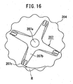
- the stirring member 207 is set on a driveshaft 2021.
- the stirring member 207 has a rotating shaft 207a set on the driveshaft 21 to be fixed, arms 207b radially extended from the outer circumference of the rotating shaft 207a, and blades 207c coupled with the arms 207b.
- WO2002/38290 for the detailed structure of this stirring member 207.
- the structure disclosed in this patent literature does not allow for replacement of a sieve, this embodiment is modified to allow for replacement of a sieve.
- the stirring member 207 is rotated in an inner region 2025 of the cylindrical sieve 201 fastened to the sieve housing 2023 to facilitate sieving of the granular material.
- the structure of this embodiment uses the stirring member, in combination with the cylindrical sieve having the corrugated sieve body 204.
- the corrugated surface of the sieve body 204 makes a space R for receiving the granular material. There is thus very little possibility that the granular material is stuck between the stirring member 207 and the sieve body 204.
- the absence of the stirring member is generally preferable to prevent potential destruction and cracking of the granular material.
- the structure of the cylindrical sifter 200 is, however, effective for the applications that require the stirring member according to the size and the properties of the granular material or grains as the sieving object.
- a frame rear end element 208a as a ring plate member is provided on the rear sieve frame 206b on the rear end of the sieve body 204, and handles 208b extended to the rear end of a non-sieved discharge chamber 2018a are attached to the frame rear end element 208a ( Figs. 8 and 10 ).
- the inner wall of the inspection door 2013 presses the rear ends of the handles 208b to restrict the motion of the sieve body 204 in the axial direction.
- Male-female fitting elements 208d are provided on the frame rear end element 208a and on a ring body 208c fastened to the sieve housing 23.
- a plurality of the fitting elements 208d are arranged along the outer periphery of the ring body 208c.
- the fitting elements 208d radially facing each other restrict the rotation of the sieve body 204.
- the inspection door 2013 of this structure serves also to fix the cylindrical sieve 201.
- the large handles 208b facilitate detachment or removal of the sieve body 204 from the cylindrical sifter 200.
- the sieve body 204 without the sieve frames 206a and 206b it is preferable to form the sieve support 2037 employed for supporting and fixing the sieve body 204 in a corrugated shape conforming with the corrugated surface of the sieve body 204 without any clearance.
- the sieve body 204 with the sieve frames 206a and 206b it is preferable to eliminate any clearance between the sieve support 2037 and the sieve frames 206a and 206b.
- the outer diameter of the cylindrical sieve 1 should be set to be smaller than the outer diameter of the cylindrical sieve 201. Such setting makes a space between the sieve support 2037 and the rotating sieve body 204 to prevent the mutual interference.
- the cylindrical sieve 1 may be replaced with the cylindrical sieve 201 according to the following procedure.
- the corresponding parts or elements are expressed by the numerals and symbols used for the cylindrical sifter 10 discussed previously.
- the procedure of replacing the cylindrical sieve 1 with the cylindrical sieve 201 untightens the bolt 31, detaches the fixture 30, pulls out the driveshaft 21 from the rotating shaft 2, and takes the cylindrical sieve 1 out of the sieving chamber 24.
- the procedure then inserts the driveshaft 21 into the rotating shaft 207a of the stirring member 207, attaches the fixture 30, tightens the bolt 31, inserts the cylindrical sieve 201, and fixes the cylindrical sieve 201 with the sieve support 2037.
- the cylindrical sieve 201 is replaced with the cylindrical sieve 1 according to the reverse procedure.
- the cylindrical sieve 201 is fixed in a non-rotatable manner in the cylindrical sifter 200.
- the non-rotatable fixation is, however, not essential, but the cylindrical sieve 201 may be fixed in a rotatable manner.
- Such flexibility for rotation does not reduce the advantages of the corrugated sieve body but has contribution to the diversified applications of the sieving operation.
- the stirring member 207 may be replaced with a stirring member 307 shown in Figs. 11 and 12 .
- the stirring member 307 includes a rotating shaft 307a detachably mounted on the driveshaft, 2021, a drum 307d fastened to the outer circumference of the rotating shaft 307a, and a plurality of blades 307c extended radially from the outer circumference and extended in the axial direction of the driveshaftf 2021.
- WO2007/129478 for the detailed structure of this stirring member 307.
- the stirring member 207 may be replaced with a stirring member 407 having front ends of the blades 307c of the stirring member 307 extended to the supply chamber 2020 ( Fig. 13 ).
- the number of blades may be changed as appropriate.
- the blades may be inclined to the axial direction of the rotating shaft.
- the cylindrical sieve 1 of the embodiment has the two support members 3 arranged at the preset interval in the axial direction.
- the cylindrical sieve may have any other number of the support members 3.
- the sieve body 4 is preferably made of a metal material having both rigidity and elasticity but may be made of any other material, such as ceramic material or plastic material.
- the cylindrical sieve 1 is assembled by welding in the above embodiment but may be assembled by any other suitable technique, for example, by using screws or other fasteners.
- the shape of the apertures 5 is not restricted to oval but may be any other suitable shape, such as rectangular.
- the present invention provides a cylindrical sieve and a cylindrical sifter having enhanced sieving efficiency of the granular material and is applicable to a wide variety of fields including food industry, pharmaceutical industry, and chemical industry.
Landscapes
- Combined Means For Separation Of Solids (AREA)
Applications Claiming Priority (2)
| Application Number | Priority Date | Filing Date | Title |
|---|---|---|---|
| JP2009136383 | 2009-06-05 | ||
| PCT/JP2010/003629 WO2010140336A1 (ja) | 2009-06-05 | 2010-05-31 | 筒形シーブ及び筒形シフタ |
Publications (3)
| Publication Number | Publication Date |
|---|---|
| EP2374548A1 EP2374548A1 (en) | 2011-10-12 |
| EP2374548A4 EP2374548A4 (en) | 2013-03-13 |
| EP2374548B1 true EP2374548B1 (en) | 2015-04-01 |
Family
ID=43297479
Family Applications (1)
| Application Number | Title | Priority Date | Filing Date |
|---|---|---|---|
| EP10783124.0A Active EP2374548B1 (en) | 2009-06-05 | 2010-05-31 | Cylindrical sieve and cylindrical sifter |
Country Status (6)
| Country | Link |
|---|---|
| US (1) | US8733552B2 (ko) |
| EP (1) | EP2374548B1 (ko) |
| JP (1) | JP5400879B2 (ko) |
| KR (1) | KR101321367B1 (ko) |
| CN (1) | CN102574159B (ko) |
| WO (1) | WO2010140336A1 (ko) |
Families Citing this family (10)
| Publication number | Priority date | Publication date | Assignee | Title |
|---|---|---|---|---|
| US20130306524A1 (en) * | 2012-05-21 | 2013-11-21 | Michael Dudley Welch | Underwater gold processing machine |
| KR101348481B1 (ko) | 2013-08-23 | 2014-01-07 | 정찬웅 | 빵 제조용 밀가루 시프터기 |
| CN106000861A (zh) * | 2015-02-13 | 2016-10-12 | 王寿南 | 一种厨用的面粉筛 |
| CN104908135A (zh) * | 2015-06-25 | 2015-09-16 | 吉首大学 | 齿筒直桨式带岔枝桑枝去皮粉碎装置 |
| CN104998733A (zh) * | 2015-08-17 | 2015-10-28 | 广州市联冠机械有限公司 | 筛网及其制造方法及设有该筛网的撕碎机 |
| CN113041901A (zh) * | 2019-12-28 | 2021-06-29 | 新沂市华瑞石英制品有限公司 | 一种石英砂提纯装置 |
| USD949218S1 (en) * | 2020-06-30 | 2022-04-19 | Bühler AG | Plan sifter |
| CN112371494A (zh) * | 2020-10-26 | 2021-02-19 | 覃永勇 | 一种钩藤钩杆分离装置 |
| CN112780896A (zh) * | 2021-01-15 | 2021-05-11 | 湖南镭目科技有限公司 | 一种冶金行业废钢识别系统 |
| CN115301532A (zh) * | 2022-07-18 | 2022-11-08 | 郧西县槐树茶叶专业合作社 | 一种茶叶筛选机的分级筛选装置 |
Citations (2)
| Publication number | Priority date | Publication date | Assignee | Title |
|---|---|---|---|---|
| US2827169A (en) * | 1954-12-07 | 1958-03-18 | Internat Pulp Products Inc | Screen plate |
| JPH0356685U (ko) * | 1989-10-04 | 1991-05-30 |
Family Cites Families (24)
| Publication number | Priority date | Publication date | Assignee | Title |
|---|---|---|---|---|
| US16495A (en) * | 1857-01-27 | Improved ore-cleaner | ||
| US71099A (en) * | 1867-11-19 | Corrugated iron revolving coal-screen | ||
| JPS4868Y1 (ko) * | 1972-02-02 | 1973-01-05 | ||
| JPS48109163U (ko) * | 1972-03-31 | 1973-12-15 | ||
| NZ182084A (en) * | 1976-09-17 | 1981-02-11 | Contra Shear Holdings | Rotating drum screen |
| JPS53109862U (ko) * | 1977-02-09 | 1978-09-02 | ||
| JPS597513B2 (ja) * | 1977-04-09 | 1984-02-18 | 株式会社 サタケ | 粒体選別機 |
| US4339043A (en) * | 1981-02-02 | 1982-07-13 | Tice Richard P | Portable mining apparatus |
| JPS6095986U (ja) | 1983-12-05 | 1985-06-29 | バンドー化学株式会社 | 円筒型篩装置における篩網取付構造 |
| JPS618488U (ja) * | 1984-06-21 | 1986-01-18 | 正起金屬加工株式會社 | 異形物選別装置 |
| JPS63109862U (ko) * | 1986-12-27 | 1988-07-15 | ||
| JPH029481A (ja) * | 1988-06-28 | 1990-01-12 | Tsumura & Co | 造粒機、整粒機、破砕機等のスクリーン |
| JPH0212487U (ko) * | 1988-07-04 | 1990-01-25 | ||
| JP3566760B2 (ja) * | 1994-10-20 | 2004-09-15 | 林太郎 薦田 | 紙おむつ等の不良品から有価物を分離回収する分離装置および分離方法 |
| JPH09220528A (ja) | 1995-12-15 | 1997-08-26 | Mishima Kosan Co Ltd | 製鉄所原料用篩部材 |
| JP3752720B2 (ja) * | 1996-04-08 | 2006-03-08 | 株式会社東洋精米機製作所 | 異物選別方法とそれを用いた異物選別装置 |
| JP3464366B2 (ja) | 1997-05-30 | 2003-11-10 | 株式会社荏原製作所 | 濃縮型凝集反応装置 |
| JP3687291B2 (ja) | 1997-08-06 | 2005-08-24 | 東ソー株式会社 | 粒状物の篩分け方法 |
| CN1221326C (zh) | 2000-11-08 | 2005-10-05 | 知嘎萨工业株式会社 | 直列式筛选机 |
| DE20214115U1 (de) | 2002-09-12 | 2004-02-12 | Maschinenbau Farwick Gmbh | Siebmaschine |
| WO2004060584A1 (ja) | 2002-12-27 | 2004-07-22 | Tsukasa Industry Co.,Ltd. | 円筒型シーブ |
| JP3973613B2 (ja) | 2003-09-29 | 2007-09-12 | 株式会社クボタ | コンバインのクラッチ操作装置 |
| CN1921957B (zh) | 2004-04-23 | 2011-04-20 | 知嘎萨工业株式会社 | 颗粒筛分器 |
| KR101113949B1 (ko) | 2006-05-10 | 2012-03-05 | 가부시키가이샤 츠카사 | 시프터 |
-
2010
- 2010-05-31 US US13/131,916 patent/US8733552B2/en active Active
- 2010-05-31 KR KR1020117016855A patent/KR101321367B1/ko active IP Right Grant
- 2010-05-31 CN CN201080024975.8A patent/CN102574159B/zh active Active
- 2010-05-31 JP JP2011518251A patent/JP5400879B2/ja active Active
- 2010-05-31 EP EP10783124.0A patent/EP2374548B1/en active Active
- 2010-05-31 WO PCT/JP2010/003629 patent/WO2010140336A1/ja active Application Filing
Patent Citations (2)
| Publication number | Priority date | Publication date | Assignee | Title |
|---|---|---|---|---|
| US2827169A (en) * | 1954-12-07 | 1958-03-18 | Internat Pulp Products Inc | Screen plate |
| JPH0356685U (ko) * | 1989-10-04 | 1991-05-30 |
Also Published As
| Publication number | Publication date |
|---|---|
| JPWO2010140336A1 (ja) | 2012-11-15 |
| KR20110105834A (ko) | 2011-09-27 |
| US8733552B2 (en) | 2014-05-27 |
| KR101321367B1 (ko) | 2013-10-28 |
| EP2374548A1 (en) | 2011-10-12 |
| CN102574159A (zh) | 2012-07-11 |
| CN102574159B (zh) | 2015-09-30 |
| WO2010140336A1 (ja) | 2010-12-09 |
| EP2374548A4 (en) | 2013-03-13 |
| JP5400879B2 (ja) | 2014-01-29 |
| US20110226676A1 (en) | 2011-09-22 |
Similar Documents
| Publication | Publication Date | Title |
|---|---|---|
| EP2374548B1 (en) | Cylindrical sieve and cylindrical sifter | |
| US20070074998A1 (en) | Method and apparatus for screening kaolin | |
| WO2019091332A1 (zh) | 网带平回筛及其进行粮食除杂的方法 | |
| JPH05505219A (ja) | ウッド粒子用スクリーン | |
| JP3628628B2 (ja) | 回転選別装置 | |
| RU2559969C1 (ru) | Сепаратор предварительной очистки | |
| CN110935545A (zh) | 一种香料加工生产用百合粉碎装置 | |
| WO2001059379A1 (en) | Flow disrupter for dryers | |
| CN207493797U (zh) | 污泥破碎机 | |
| RU2464110C1 (ru) | Барабанный скальператор сыпучих материалов | |
| CA2852986C (en) | Recovery of aleurone-rich flour from bran | |
| JP5301343B2 (ja) | 円筒形シフタ | |
| CN202387665U (zh) | 一种螺旋分级清理筛 | |
| US20110005980A1 (en) | Sifter | |
| AU2003202339B2 (en) | Trommel | |
| CN209613112U (zh) | 一种餐厨垃圾破碎制浆及筛分一体化处理设备 | |
| WO2022059258A1 (ja) | スパイラルコンベアおよびフィルターユニット | |
| RU57646U1 (ru) | Барабанное сито | |
| JP2003126779A (ja) | 粒状物の選別装置 | |
| CN210304466U (zh) | 一种具有防堵塞功能的筛分机 | |
| US4345720A (en) | Apparatus for the treatment of solid, granular and/or lumpy materials | |
| JP5204318B1 (ja) | 破砕機 | |
| RU2385775C1 (ru) | Центробежно-решетный сепаратор | |
| CA2522306A1 (en) | Method and apparatus for screening kaolin | |
| JP2007014914A (ja) | ドラムスクリーン |
Legal Events
| Date | Code | Title | Description |
|---|---|---|---|
| PUAI | Public reference made under article 153(3) epc to a published international application that has entered the european phase |
Free format text: ORIGINAL CODE: 0009012 |
|
| 17P | Request for examination filed |
Effective date: 20110708 |
|
| AK | Designated contracting states |
Kind code of ref document: A1 Designated state(s): AL AT BE BG CH CY CZ DE DK EE ES FI FR GB GR HR HU IE IS IT LI LT LU LV MC MK MT NL NO PL PT RO SE SI SK SM TR |
|
| DAX | Request for extension of the european patent (deleted) | ||
| A4 | Supplementary search report drawn up and despatched |
Effective date: 20130207 |
|
| RIC1 | Information provided on ipc code assigned before grant |
Ipc: B07B 1/24 20060101ALI20130201BHEP Ipc: B07B 1/46 20060101ALI20130201BHEP Ipc: B07B 13/16 20060101ALI20130201BHEP Ipc: B07B 1/22 20060101AFI20130201BHEP |
|
| 17Q | First examination report despatched |
Effective date: 20140515 |
|
| GRAP | Despatch of communication of intention to grant a patent |
Free format text: ORIGINAL CODE: EPIDOSNIGR1 |
|
| INTG | Intention to grant announced |
Effective date: 20141210 |
|
| GRAS | Grant fee paid |
Free format text: ORIGINAL CODE: EPIDOSNIGR3 |
|
| GRAA | (expected) grant |
Free format text: ORIGINAL CODE: 0009210 |
|
| AK | Designated contracting states |
Kind code of ref document: B1 Designated state(s): AL AT BE BG CH CY CZ DE DK EE ES FI FR GB GR HR HU IE IS IT LI LT LU LV MC MK MT NL NO PL PT RO SE SI SK SM TR |
|
| REG | Reference to a national code |
Ref country code: GB Ref legal event code: FG4D |
|
| REG | Reference to a national code |
Ref country code: CH Ref legal event code: EP |
|
| REG | Reference to a national code |
Ref country code: IE Ref legal event code: FG4D |
|
| REG | Reference to a national code |
Ref country code: DE Ref legal event code: R096 Ref document number: 602010023629 Country of ref document: DE Effective date: 20150513 |
|
| REG | Reference to a national code |
Ref country code: AT Ref legal event code: REF Ref document number: 718759 Country of ref document: AT Kind code of ref document: T Effective date: 20150515 |
|
| REG | Reference to a national code |
Ref country code: NL Ref legal event code: VDEP Effective date: 20150401 |
|
| REG | Reference to a national code |
Ref country code: AT Ref legal event code: MK05 Ref document number: 718759 Country of ref document: AT Kind code of ref document: T Effective date: 20150401 |
|
| REG | Reference to a national code |
Ref country code: LT Ref legal event code: MG4D |
|
| PG25 | Lapsed in a contracting state [announced via postgrant information from national office to epo] |
Ref country code: NL Free format text: LAPSE BECAUSE OF FAILURE TO SUBMIT A TRANSLATION OF THE DESCRIPTION OR TO PAY THE FEE WITHIN THE PRESCRIBED TIME-LIMIT Effective date: 20150401 |
|
| PG25 | Lapsed in a contracting state [announced via postgrant information from national office to epo] |
Ref country code: ES Free format text: LAPSE BECAUSE OF FAILURE TO SUBMIT A TRANSLATION OF THE DESCRIPTION OR TO PAY THE FEE WITHIN THE PRESCRIBED TIME-LIMIT Effective date: 20150401 Ref country code: PT Free format text: LAPSE BECAUSE OF FAILURE TO SUBMIT A TRANSLATION OF THE DESCRIPTION OR TO PAY THE FEE WITHIN THE PRESCRIBED TIME-LIMIT Effective date: 20150803 Ref country code: FI Free format text: LAPSE BECAUSE OF FAILURE TO SUBMIT A TRANSLATION OF THE DESCRIPTION OR TO PAY THE FEE WITHIN THE PRESCRIBED TIME-LIMIT Effective date: 20150401 Ref country code: CZ Free format text: LAPSE BECAUSE OF FAILURE TO SUBMIT A TRANSLATION OF THE DESCRIPTION OR TO PAY THE FEE WITHIN THE PRESCRIBED TIME-LIMIT Effective date: 20150401 Ref country code: LT Free format text: LAPSE BECAUSE OF FAILURE TO SUBMIT A TRANSLATION OF THE DESCRIPTION OR TO PAY THE FEE WITHIN THE PRESCRIBED TIME-LIMIT Effective date: 20150401 Ref country code: NO Free format text: LAPSE BECAUSE OF FAILURE TO SUBMIT A TRANSLATION OF THE DESCRIPTION OR TO PAY THE FEE WITHIN THE PRESCRIBED TIME-LIMIT Effective date: 20150701 Ref country code: HR Free format text: LAPSE BECAUSE OF FAILURE TO SUBMIT A TRANSLATION OF THE DESCRIPTION OR TO PAY THE FEE WITHIN THE PRESCRIBED TIME-LIMIT Effective date: 20150401 |
|
| PG25 | Lapsed in a contracting state [announced via postgrant information from national office to epo] |
Ref country code: GR Free format text: LAPSE BECAUSE OF FAILURE TO SUBMIT A TRANSLATION OF THE DESCRIPTION OR TO PAY THE FEE WITHIN THE PRESCRIBED TIME-LIMIT Effective date: 20150702 Ref country code: LV Free format text: LAPSE BECAUSE OF FAILURE TO SUBMIT A TRANSLATION OF THE DESCRIPTION OR TO PAY THE FEE WITHIN THE PRESCRIBED TIME-LIMIT Effective date: 20150401 Ref country code: AT Free format text: LAPSE BECAUSE OF FAILURE TO SUBMIT A TRANSLATION OF THE DESCRIPTION OR TO PAY THE FEE WITHIN THE PRESCRIBED TIME-LIMIT Effective date: 20150401 Ref country code: IS Free format text: LAPSE BECAUSE OF FAILURE TO SUBMIT A TRANSLATION OF THE DESCRIPTION OR TO PAY THE FEE WITHIN THE PRESCRIBED TIME-LIMIT Effective date: 20150801 |
|
| REG | Reference to a national code |
Ref country code: CH Ref legal event code: PL |
|
| REG | Reference to a national code |
Ref country code: DE Ref legal event code: R097 Ref document number: 602010023629 Country of ref document: DE |
|
| PG25 | Lapsed in a contracting state [announced via postgrant information from national office to epo] |
Ref country code: DK Free format text: LAPSE BECAUSE OF FAILURE TO SUBMIT A TRANSLATION OF THE DESCRIPTION OR TO PAY THE FEE WITHIN THE PRESCRIBED TIME-LIMIT Effective date: 20150401 Ref country code: CH Free format text: LAPSE BECAUSE OF NON-PAYMENT OF DUE FEES Effective date: 20150531 Ref country code: EE Free format text: LAPSE BECAUSE OF FAILURE TO SUBMIT A TRANSLATION OF THE DESCRIPTION OR TO PAY THE FEE WITHIN THE PRESCRIBED TIME-LIMIT Effective date: 20150401 Ref country code: MC Free format text: LAPSE BECAUSE OF FAILURE TO SUBMIT A TRANSLATION OF THE DESCRIPTION OR TO PAY THE FEE WITHIN THE PRESCRIBED TIME-LIMIT Effective date: 20150401 Ref country code: LI Free format text: LAPSE BECAUSE OF NON-PAYMENT OF DUE FEES Effective date: 20150531 |
|
| PLBE | No opposition filed within time limit |
Free format text: ORIGINAL CODE: 0009261 |
|
| STAA | Information on the status of an ep patent application or granted ep patent |
Free format text: STATUS: NO OPPOSITION FILED WITHIN TIME LIMIT |
|
| REG | Reference to a national code |
Ref country code: IE Ref legal event code: MM4A |
|
| PG25 | Lapsed in a contracting state [announced via postgrant information from national office to epo] |
Ref country code: RO Free format text: LAPSE BECAUSE OF NON-PAYMENT OF DUE FEES Effective date: 20150401 Ref country code: SK Free format text: LAPSE BECAUSE OF FAILURE TO SUBMIT A TRANSLATION OF THE DESCRIPTION OR TO PAY THE FEE WITHIN THE PRESCRIBED TIME-LIMIT Effective date: 20150401 Ref country code: PL Free format text: LAPSE BECAUSE OF FAILURE TO SUBMIT A TRANSLATION OF THE DESCRIPTION OR TO PAY THE FEE WITHIN THE PRESCRIBED TIME-LIMIT Effective date: 20150401 |
|
| 26N | No opposition filed |
Effective date: 20160105 |
|
| PG25 | Lapsed in a contracting state [announced via postgrant information from national office to epo] |
Ref country code: IE Free format text: LAPSE BECAUSE OF NON-PAYMENT OF DUE FEES Effective date: 20150531 |
|
| REG | Reference to a national code |
Ref country code: FR Ref legal event code: PLFP Year of fee payment: 7 |
|
| PG25 | Lapsed in a contracting state [announced via postgrant information from national office to epo] |
Ref country code: SI Free format text: LAPSE BECAUSE OF FAILURE TO SUBMIT A TRANSLATION OF THE DESCRIPTION OR TO PAY THE FEE WITHIN THE PRESCRIBED TIME-LIMIT Effective date: 20150401 |
|
| PG25 | Lapsed in a contracting state [announced via postgrant information from national office to epo] |
Ref country code: BE Free format text: LAPSE BECAUSE OF FAILURE TO SUBMIT A TRANSLATION OF THE DESCRIPTION OR TO PAY THE FEE WITHIN THE PRESCRIBED TIME-LIMIT Effective date: 20150401 |
|
| PG25 | Lapsed in a contracting state [announced via postgrant information from national office to epo] |
Ref country code: MT Free format text: LAPSE BECAUSE OF FAILURE TO SUBMIT A TRANSLATION OF THE DESCRIPTION OR TO PAY THE FEE WITHIN THE PRESCRIBED TIME-LIMIT Effective date: 20150401 |
|
| REG | Reference to a national code |
Ref country code: FR Ref legal event code: PLFP Year of fee payment: 8 |
|
| PG25 | Lapsed in a contracting state [announced via postgrant information from national office to epo] |
Ref country code: SM Free format text: LAPSE BECAUSE OF FAILURE TO SUBMIT A TRANSLATION OF THE DESCRIPTION OR TO PAY THE FEE WITHIN THE PRESCRIBED TIME-LIMIT Effective date: 20150401 Ref country code: BG Free format text: LAPSE BECAUSE OF FAILURE TO SUBMIT A TRANSLATION OF THE DESCRIPTION OR TO PAY THE FEE WITHIN THE PRESCRIBED TIME-LIMIT Effective date: 20150401 Ref country code: HU Free format text: LAPSE BECAUSE OF FAILURE TO SUBMIT A TRANSLATION OF THE DESCRIPTION OR TO PAY THE FEE WITHIN THE PRESCRIBED TIME-LIMIT; INVALID AB INITIO Effective date: 20100531 |
|
| PG25 | Lapsed in a contracting state [announced via postgrant information from national office to epo] |
Ref country code: CY Free format text: LAPSE BECAUSE OF FAILURE TO SUBMIT A TRANSLATION OF THE DESCRIPTION OR TO PAY THE FEE WITHIN THE PRESCRIBED TIME-LIMIT Effective date: 20150401 Ref country code: SE Free format text: LAPSE BECAUSE OF FAILURE TO SUBMIT A TRANSLATION OF THE DESCRIPTION OR TO PAY THE FEE WITHIN THE PRESCRIBED TIME-LIMIT Effective date: 20150401 |
|
| PG25 | Lapsed in a contracting state [announced via postgrant information from national office to epo] |
Ref country code: TR Free format text: LAPSE BECAUSE OF FAILURE TO SUBMIT A TRANSLATION OF THE DESCRIPTION OR TO PAY THE FEE WITHIN THE PRESCRIBED TIME-LIMIT Effective date: 20150401 |
|
| PG25 | Lapsed in a contracting state [announced via postgrant information from national office to epo] |
Ref country code: LU Free format text: LAPSE BECAUSE OF NON-PAYMENT OF DUE FEES Effective date: 20150531 |
|
| REG | Reference to a national code |
Ref country code: FR Ref legal event code: PLFP Year of fee payment: 9 |
|
| PG25 | Lapsed in a contracting state [announced via postgrant information from national office to epo] |
Ref country code: MK Free format text: LAPSE BECAUSE OF FAILURE TO SUBMIT A TRANSLATION OF THE DESCRIPTION OR TO PAY THE FEE WITHIN THE PRESCRIBED TIME-LIMIT Effective date: 20150401 |
|
| PG25 | Lapsed in a contracting state [announced via postgrant information from national office to epo] |
Ref country code: AL Free format text: LAPSE BECAUSE OF FAILURE TO SUBMIT A TRANSLATION OF THE DESCRIPTION OR TO PAY THE FEE WITHIN THE PRESCRIBED TIME-LIMIT Effective date: 20150401 |
|
| PGFP | Annual fee paid to national office [announced via postgrant information from national office to epo] |
Ref country code: FR Payment date: 20230328 Year of fee payment: 14 |
|
| PGFP | Annual fee paid to national office [announced via postgrant information from national office to epo] |
Ref country code: IT Payment date: 20230328 Year of fee payment: 14 Ref country code: DE Payment date: 20230328 Year of fee payment: 14 |
|
| PGFP | Annual fee paid to national office [announced via postgrant information from national office to epo] |
Ref country code: GB Payment date: 20240304 Year of fee payment: 15 |