EP2372983B1 - Exécution d'application dans un terminal de communication mobile lors du placement de ce terminal dans un chargeur - Google Patents
Exécution d'application dans un terminal de communication mobile lors du placement de ce terminal dans un chargeur Download PDFInfo
- Publication number
- EP2372983B1 EP2372983B1 EP10191495.0A EP10191495A EP2372983B1 EP 2372983 B1 EP2372983 B1 EP 2372983B1 EP 10191495 A EP10191495 A EP 10191495A EP 2372983 B1 EP2372983 B1 EP 2372983B1
- Authority
- EP
- European Patent Office
- Prior art keywords
- section
- mobile communication
- communication terminal
- application
- style
- Prior art date
- Legal status (The legal status is an assumption and is not a legal conclusion. Google has not performed a legal analysis and makes no representation as to the accuracy of the status listed.)
- Expired - Fee Related
Links
Images


Classifications
-
- H—ELECTRICITY
- H04—ELECTRIC COMMUNICATION TECHNIQUE
- H04N—PICTORIAL COMMUNICATION, e.g. TELEVISION
- H04N21/00—Selective content distribution, e.g. interactive television or video on demand [VOD]
- H04N21/40—Client devices specifically adapted for the reception of or interaction with content, e.g. set-top-box [STB]; Operations thereof
- H04N21/43—Processing of content or additional data, e.g. demultiplexing additional data from a digital video stream; Elementary client operations, e.g. monitoring of home network or synchronising decoder's clock; Client middleware
- H04N21/443—OS processes, e.g. booting an STB, implementing a Java virtual machine in an STB or power management in an STB
- H04N21/4436—Power management, e.g. shutting down unused components of the receiver
-
- H—ELECTRICITY
- H04—ELECTRIC COMMUNICATION TECHNIQUE
- H04M—TELEPHONIC COMMUNICATION
- H04M1/00—Substation equipment, e.g. for use by subscribers
- H04M1/02—Constructional features of telephone sets
- H04M1/0202—Portable telephone sets, e.g. cordless phones, mobile phones or bar type handsets
- H04M1/0206—Portable telephones comprising a plurality of mechanically joined movable body parts, e.g. hinged housings
- H04M1/0241—Portable telephones comprising a plurality of mechanically joined movable body parts, e.g. hinged housings using relative motion of the body parts to change the operational status of the telephone set, e.g. switching on/off, answering incoming call
-
- H—ELECTRICITY
- H04—ELECTRIC COMMUNICATION TECHNIQUE
- H04M—TELEPHONIC COMMUNICATION
- H04M1/00—Substation equipment, e.g. for use by subscribers
- H04M1/72—Mobile telephones; Cordless telephones, i.e. devices for establishing wireless links to base stations without route selection
- H04M1/724—User interfaces specially adapted for cordless or mobile telephones
- H04M1/72448—User interfaces specially adapted for cordless or mobile telephones with means for adapting the functionality of the device according to specific conditions
-
- H—ELECTRICITY
- H04—ELECTRIC COMMUNICATION TECHNIQUE
- H04N—PICTORIAL COMMUNICATION, e.g. TELEVISION
- H04N21/00—Selective content distribution, e.g. interactive television or video on demand [VOD]
- H04N21/40—Client devices specifically adapted for the reception of or interaction with content, e.g. set-top-box [STB]; Operations thereof
- H04N21/41—Structure of client; Structure of client peripherals
- H04N21/414—Specialised client platforms, e.g. receiver in car or embedded in a mobile appliance
- H04N21/41407—Specialised client platforms, e.g. receiver in car or embedded in a mobile appliance embedded in a portable device, e.g. video client on a mobile phone, PDA, laptop
-
- H—ELECTRICITY
- H04—ELECTRIC COMMUNICATION TECHNIQUE
- H04N—PICTORIAL COMMUNICATION, e.g. TELEVISION
- H04N21/00—Selective content distribution, e.g. interactive television or video on demand [VOD]
- H04N21/40—Client devices specifically adapted for the reception of or interaction with content, e.g. set-top-box [STB]; Operations thereof
- H04N21/43—Processing of content or additional data, e.g. demultiplexing additional data from a digital video stream; Elementary client operations, e.g. monitoring of home network or synchronising decoder's clock; Client middleware
- H04N21/442—Monitoring of processes or resources, e.g. detecting the failure of a recording device, monitoring the downstream bandwidth, the number of times a movie has been viewed, the storage space available from the internal hard disk
- H04N21/44231—Monitoring of peripheral device or external card, e.g. to detect processing problems in a handheld device or the failure of an external recording device
-
- H—ELECTRICITY
- H04—ELECTRIC COMMUNICATION TECHNIQUE
- H04N—PICTORIAL COMMUNICATION, e.g. TELEVISION
- H04N21/00—Selective content distribution, e.g. interactive television or video on demand [VOD]
- H04N21/40—Client devices specifically adapted for the reception of or interaction with content, e.g. set-top-box [STB]; Operations thereof
- H04N21/45—Management operations performed by the client for facilitating the reception of or the interaction with the content or administrating data related to the end-user or to the client device itself, e.g. learning user preferences for recommending movies, resolving scheduling conflicts
- H04N21/462—Content or additional data management, e.g. creating a master electronic program guide from data received from the Internet and a Head-end, controlling the complexity of a video stream by scaling the resolution or bit-rate based on the client capabilities
- H04N21/4622—Retrieving content or additional data from different sources, e.g. from a broadcast channel and the Internet
-
- H—ELECTRICITY
- H04—ELECTRIC COMMUNICATION TECHNIQUE
- H04N—PICTORIAL COMMUNICATION, e.g. TELEVISION
- H04N21/00—Selective content distribution, e.g. interactive television or video on demand [VOD]
- H04N21/40—Client devices specifically adapted for the reception of or interaction with content, e.g. set-top-box [STB]; Operations thereof
- H04N21/47—End-user applications
- H04N21/472—End-user interface for requesting content, additional data or services; End-user interface for interacting with content, e.g. for content reservation or setting reminders, for requesting event notification, for manipulating displayed content
- H04N21/47214—End-user interface for requesting content, additional data or services; End-user interface for interacting with content, e.g. for content reservation or setting reminders, for requesting event notification, for manipulating displayed content for content reservation or setting reminders; for requesting event notification, e.g. of sport results or stock market
-
- H—ELECTRICITY
- H04—ELECTRIC COMMUNICATION TECHNIQUE
- H04N—PICTORIAL COMMUNICATION, e.g. TELEVISION
- H04N21/00—Selective content distribution, e.g. interactive television or video on demand [VOD]
- H04N21/40—Client devices specifically adapted for the reception of or interaction with content, e.g. set-top-box [STB]; Operations thereof
- H04N21/47—End-user applications
- H04N21/482—End-user interface for program selection
-
- H—ELECTRICITY
- H04—ELECTRIC COMMUNICATION TECHNIQUE
- H04N—PICTORIAL COMMUNICATION, e.g. TELEVISION
- H04N21/00—Selective content distribution, e.g. interactive television or video on demand [VOD]
- H04N21/40—Client devices specifically adapted for the reception of or interaction with content, e.g. set-top-box [STB]; Operations thereof
- H04N21/47—End-user applications
- H04N21/485—End-user interface for client configuration
- H04N21/4852—End-user interface for client configuration for modifying audio parameters, e.g. switching between mono and stereo
-
- H—ELECTRICITY
- H04—ELECTRIC COMMUNICATION TECHNIQUE
- H04M—TELEPHONIC COMMUNICATION
- H04M1/00—Substation equipment, e.g. for use by subscribers
- H04M1/02—Constructional features of telephone sets
- H04M1/0202—Portable telephone sets, e.g. cordless phones, mobile phones or bar type handsets
- H04M1/0206—Portable telephones comprising a plurality of mechanically joined movable body parts, e.g. hinged housings
- H04M1/0208—Portable telephones comprising a plurality of mechanically joined movable body parts, e.g. hinged housings characterized by the relative motions of the body parts
- H04M1/021—Portable telephones comprising a plurality of mechanically joined movable body parts, e.g. hinged housings characterized by the relative motions of the body parts using combined folding and rotation motions
Definitions
- the present invention relates to a mobile communication terminal and a program and, more particularly to a movable communication terminal suitable for executing various functions.
- the cellular phone can double as a television receiver and an audio playback device.
- the housing of a mobile communication terminal is changed in multiple kinds of styles, so that the style, which matches the function to be used, can be achieved.
- the mobile communication terminal can be employed for not only portable use but also domestic use as an information processor, home electronic appliance in some cases.
- the mobile communication terminal is mounted on a charging base (cradle, stand) and is used with commercial power supply in many cases.
- a method is disclosed in which a device is mounted on a charging base and a television reception is performed by an antenna line connected to the charging base to obtain a good receiving condition.
- the above method can provide the good receiving condition; however, manual operations such as channel selection relating to the television reception are required for users, resulting in low user convenience.
- Reference US 2003/103091 discloses an electronic device that includes a housing, a plurality of modules, a sensor and a selection mechanism.
- the housing has multiple housing segments, with each segment housing one of the plurality of modules.
- the sensor detects an orientation of the electronic device.
- the selection mechanism automatically selects at least one, but nor all, of the plurality of modules to be active, based on the detected orientation of the electronic device.
- Reference WO 03/077087 discloses a portable electronic device which comprises position sensors to enable it to determine its arrangement in space.
- the device can be operated in different modes of operation, such as a mobile telephone or a PDA, for example.
- a switch is made between different modes of operation, with, for example, the upright position activating the mobile telephone mode and the horizontal position the PDA mode.
- the switch between different modes of operation by means of a change in position/orientation allows the user to operate the device intuitively.
- an object of the present invention is to provide a mobile communication terminal having higher user convenience.
- a first embodiment of the present invention will explain a case in which the present invention is applied to a mobile communication terminal used in a cellular phone, PHS (Personal Handyphone System).
- a mobile communication terminal 10 according to this embodiment has a television reception function that receives a television airwave and outputs the airwave in addition to a voice call function (phone function) as a basic function.
- a predetermined charging base (cradle, stand) is used in charging a battery as an operation power source for the mobile communication terminal 10 or in driving the mobile communication terminal 10 with commercial power supply.
- the mobile communication terminal 10 is mounted on a cradle 11 as shown in FIG. 1 to perform charging.
- the mobile communication terminal 10 is configured to be foldable by two movable housing sections (housings 10A and 10B), which are connected by a rotational hinge RH as shown in FIGS. 1 and 2 , and the mobile communication terminal 10 is mounted on the cradle 11 while being folded as illustrated in FIG. 1 to perform charging using the cradle 11.
- the television reception function of the mobile communication terminal 10 is used while being mounted on the cradle 11. Accordingly, as shown in FIG. 1 , the mobile communication terminal 10 is folded in such way to expose a display screen (display section 141) of the mobile communication terminal 10 and the mobile communication terminal 10 is mounted on the cradle 11 in such a way that the display surface is directed to the front side of the cradle 11 and that a display direction is correctly set.
- the mobile communication terminal 10 is mounted on the cradle 11 in such a way that the longitudinal direction of the display screen corresponds to the horizontal direction in order to provide an appropriate display of the television screen. Accordingly, regarding connectors for making connection between the mobile communication terminal 10 and the cradle 10, one is placed on the side surface portion of the mobile communication terminal 10. Then, the other is placed on the mounting surface of the cradle 11 and these connectors are engaged with each other when the folded mobile communication terminal 10 is mounted on the cradle 11.
- FIG. 3 is a block diagram showing the configuration of the mobile communication terminal 10.
- the mobile communication terminal 10 includes a control section 110, a communication control section 120, an input section 130, an output section 140, a tuner section 150, a connector section 160, a power supply section 170, a storage section 180, and the like.
- the control section 110 includes, for example, a CPU (Central Processing Unit) and a predetermined storage device (RAM (Random Access Memory), etc.) as a work area, and controls the respective sections of the mobile communication terminal 10 and executes each processing described later based on a predetermined operation program stored in the storage section 180. It should be noted that the below-described components of the mobile communication terminal 10 are connected to the control section 110, respectively, and data exchange among the respective components is assumed to be performed via the control section 110.
- a CPU Central Processing Unit
- RAM Random Access Memory
- the communication control section 120 includes, for instance, a predetermined radio communication circuit and performs radio communication through a predetermined antenna section 124.
- the communication control section 120 further includes a speech communication section 121, a data communication section 122, a television reception section 123, and the like.
- the speech communication section 121 controls communication in connection with the telephone function (voice call function) of the mobile communication terminal 10.
- the speech communication section 121 controls the antenna section 124 to perform radio communication for a voice call via a telephone network such as a mobile communication network and to perform speech coding and decoding.
- the data communication section 122 controls communication in connection with the data communication function of the mobile communication terminal 10. In this embodiment, for example, supposing that data communication is performed via an IP network such as the Internet, and the data communication section 122 controls the antenna section 124 to thereby perform radio connection to the data communication network and data transmission and reception.
- IP network such as the Internet
- the speech communication section 121 and data communication section 122 perform radio communication with a base station provided by a provider (so-called carrier) that offers mobile communication services to the mobile communication terminal 10.
- a provider so-called carrier
- the television reception section (TV reception section) 123 receives a television airwave through the antenna section 124 in cooperation with the tuner section 150 (to be specifically described).
- the antenna section 124 includes, for example, a predetermined antenna circuit, an antenna line, etc, and is provided for at least both the mobile communication and the television airwave reception.
- the input section 130 includes an operation section 131 and a speech input section 132 ( FIG. 2A ), and functions as an interface for the user to input data to the mobile communication terminal 10.
- the operation section 131 includes predetermined buttons and keys (for example, character keys (ten keys), function buttons, directional keys, etc) ( FIG.2A ) and causes an input signal to be input to the control section 110 according to a user operation.
- predetermined buttons and keys for example, character keys (ten keys), function buttons, directional keys, etc.
- the speech input section 132 includes, for example, a microphone, and inputs user speech at the speech communication.
- the output section 140 includes a display section 141 and a speech output section 142 ( FIG. 2 ) and outputs various information.
- the display section 141 includes, for example, a liquid crystal display device, and displays various screens relating to the functions of the mobile communication terminal 10.
- the display section 141 is used to output and display an image of the television broadcast received by the television reception function of the mobile communication terminal 10.
- the speech output section 142 includes, for example, a speaker, and outputs sound of the television broadcast in addition to a ring alert and a phone voice at the speech communication.
- the tuner section 150 includes a tuner circuit for television broadcast reception and performs channel selection for a television broadcast to be received in cooperation with the control section 110.
- the connector section 160 is a connector for making connection between the cradle 11 and this connector section and includes a receiving terminal.
- the connector section 160 is paired with a feeding connector provided in the cradle 11, and these connectors are connected to each other, so that power is received from the cradle 11 and supplied to the power supply section 170 through the connector section 160.
- the power supply section 170 includes a predetermined power circuit, a rechargeable buttery and the like, and charges the battery with the commercial power supplied via the connector section 160 connected to the cradle 11, and supplies power sent from the cradle 11 and power stored in the battery to each component of the mobile communication terminal 10.
- the storage section 180 includes a predetermined storage device such as a ROM (Read Only Memory), a flash memory, etc., and stores data necessary for executing each processing and data generated by execution of each processing, in addition to operation programs executed by the control section 110. Particularly, in this embodiment, the storage section 180 stores setting information (to be specifically described) on the television reception function of the mobile communication terminal 10.
- a predetermined storage device such as a ROM (Read Only Memory), a flash memory, etc.
- the storage section 180 stores setting information (to be specifically described) on the television reception function of the mobile communication terminal 10.
- the operation programs stored in the storage section 180 include an operation program for implementing each processing to be described later in addition to an arbitrary basic program that controls the base operation of the mobile communication terminal 10.
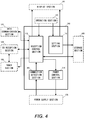
- the control section 110 executes these operation programs to thereby implement the below-described processing by the mobile communication terminal 10. Namely, execution of the operation programs stored in the storage section 180 causes the control section 110 to function as components shown in FIG. 4 .
- the control section 110 functions as a connection detection section 111, a setting section 112, a reception control section 113, and a power control section 114.
- connection detection section 111 detects connection and disconnection between the mobile communication terminal 10 and the cradle 11 in cooperation with the power supply section 170.
- the setting section 112 performs processing on various settings (hereinafter referred to as "reception setting") relating to the television reception function in cooperation with the operation section 131 and the storage section 180.
- the setting section 112 creates setting information based on the user operation of the operation section 131, changes setting, and stores the result in the storage section 180. It should be noted that the setting section 112 creates various screens necessary for reception setting and causes the result to be displayed on the display section 141.
- the reception control section 113 controls the communication control section 120 and the tuner section 150 based on the setting information to execute the television reception operation based on the setting information. It should be noted that control by the reception control section 113 is implemented by executing an application program of the television reception function. Accordingly, the reception control section 113 performs processing relating to display of the television image and sound playback in cooperation with the output section 140, in addition to control of the communication control section 120 and the tuner section 150. Moreover, the reception control section 113 acquires, for instance, an EPG (electronic program guide) via the Internet in cooperation with the data communication section 122.
- EPG electronic program guide
- the power control section 114 controls the power supply section 170 based on the setting information to turn on and off the mobile communication terminal 10.
- the aforementioned functional configuration is logically implemented by the control section 110.
- the aforementioned functions are configured by a dedicated circuit such as an ASIC (Application Specific Integrated Circuit), so that these functions may be implemented by the physical configuration.
- the control section 110 performs a timer operation for time display, thereby making it possible to acquire current time information at any time.
- the aforementioned components of the mobile communication terminal 10 are those necessary for implementing the present invention and other components necessary for the basic functions as the mobile communication terminal and components necessary for various additional functions may be provided as required.
- the cradle 11 when the mobile communication terminal 10 is mounted on the cradle 11, the cradle 11 performs charging.
- the cradle 11 includes a housing on which the mobile communication terminal 10 is mountable as illustrated in FIG. 1 , and an outlet and a cord for commercial power to acquire commercial power.
- the feeding connector is provided at a position where engagement with the connector section 160 is made when the mobile communication terminal 10 is mounted thereon.
- setting processing which is executed when the mobile communication terminal 10 performs reception setting, will be explained with reference to a flow chart shown in FIG. 5 .
- This "setting processing” is started at the time when the user operates the operation section 131 to instruct the start of setting.
- the setting section 112 displays a "mode menu screen" for causing the user to select a setting mode on the display section 141 (step S1101).
- a "channel mode” is a mode that sets a viewing channel and time by a user manual operation
- the program guide mode is a mode that performs setting based on the electronic program guide provided via the Internet.
- mode menu screen As illustrated in FIG. 6A , on the "mode menu screen", either mode is selectably displayed. The user operates the operation section 131 according to the display and selects a desired setting mode.
- the setting section 112 displays a "default channel designation screen" as shown in FIG. 6B on the display section 141 (step S1103).
- the "default channel designation screen” is a screen for selecting whether the default channel should be designated and for selecting a channel when the default channel is designated.
- the default channel here is a channel for starting reception when the television reception function of the mobile communication terminal 10 is started.
- the user operates the operation section 131 to perform selection whether the default channel should be designated and selection for a channel as a default channel.
- the setting section 112 creates setting information, which brings information, indicating the selected setting mode (namely, channel mode) and a channel selected as a default channel, into correspondence with information indicating that the relevant channel is the default channel (step S1108), and stores the created setting information in the storage section 180 (step S1109), and ends processing.
- step S1104 when the default channel is not designated (step S1104: No), the setting section 112 displays a "timer setting screen" as illustrated in FIG. 6C on the display section 141 (step S1105). As illustrated in the figure, on the "timer setting screen", a desired channel to be viewed and a reception start time zone of the relevant channel are selectably displayed.
- the user operates the operation section 131 to select the desired channel to be viewed and the reception start time zone of the relevant channel.
- information which indicates the user designated channel and the reception start time zone of the relevant channel, are input to the control section 110 (step S1106).
- a button for selecting continuation of the timer setting or a button for selecting completion of thereof are displayed on the "timer setting screen".
- a button for selecting continuation of the timer setting or a button for selecting completion of thereof are displayed on the "timer setting screen”.
- step S1107: No processing goes back to step S1105 and timer setting is further performed.
- step S1107: Yes the setting section 112 creates setting information, which brings information, indicating the selected setting mode (namely, channel mode), into correspondence with information indicating the timer-set channel and the reception start time zone (step S1108), and stores the created setting information in the storage section 180 (step S1109), and ends processing.
- step S1102 when the "program guide mode" is selected as the setting mode (step S1102: No), the setting section 112 creates setting information, which indicates that the selected setting mode is the program guide mode, (step S1108), and stores the created setting information in the storage section 180 (step S1109), and ends processing.
- setting processing By the execution of setting processing as mentioned, the operation relating to the television reception by the mobile communication terminal 10 is set and setting information, which indicates the contents of setting, is stored in the storage section 180.
- the power supply section 170 notifies the control section 110 of the power supply.
- the connection detection section 111 detects that the mobile communication terminal 10 is connected to the cradle 11 based on a notification from the power supply section 170. It should be noted that the mobile communication terminal 10 is connected to the cradle 11 while being powered on.
- the reception control section 113 gains access to the storage section 180 to determine whether setting information relating to the reception setting is stored therein (step S1201).
- step S1201: No When the setting information of the reception setting is not stored in the storage section 180 (step S1201: No), processing is directly ended.
- step S1201 when the setting information is stored in the storage section 180 (step S1201: Yes), the reception control section 113 determines whether the setting mode set in the relevant setting information is the channel mode (step S1202).
- the reception control section 113 executes "program guide acquisition processing" for acquiring electronic program guide data (step S1300). The details on the program guide acquisition processing will be described later.
- the reception control section 113 determines whether the reception start time zone is designated in the reception setting included in the relevant setting information (whether timer is set) (step S1203).
- the reception control section 113 determines whether there is a reception setting in which the reception start time zone, which corresponds to the current time acquired by the timer operation, is designated (step S1204).
- the reception control section 113 causes the tuner section 150 to execute to select a channel designated by the relevant reception setting (step S1205).
- the reception control section 113 gains access to the storage section 180 to delete the setting information relating to the relevant reception setting (step S1206).
- the reception control section 113 causes the television reception section 123 to receive an airwave of the channel selected by the tuner section 150 (step S1207).
- the reception control section 113 waits until the current time reaches the relevant time zone. Then, at the time when the current time reaches the designated reception start time, the reception control section 113 causes the channel selection and reception to be started (steps S1205, S1207).
- the reception control section 113 causes the tuner section 150 to select the relevant channel (step S1205). Then, after deleting the setting information (step S1206), the reception control section 113 causes the television reception section 123 to execute the reception of the airwave of the channel selected by the tuner section 150 (step 1207).
- the reception of the set channel is started at the time when the mobile communication terminal 10 is mounted on the cradle 11.
- step S1206 When the tuner section 150 selects the channel based on the setting information, the relevant setting information is deleted in step S1206. However, for example, when two or more timer settings are provided, setting information relating to the other timer settings remains in the storage section 180 (step S1208: Yes). In this case, processing goes back to step S1202 to execute the operation based on the remaining setting information. Namely, in the case where the plurality of timer settings is provided, processing in steps S1204 to S1206 is performed in connection with the reception setting where a next reception start time zone is designated, so that the reception of the set channel is executed at the time when the current time reaches a next reception start time zone. As a result, in the case of a plurality of reception settings where the reception start time zone is designated, when the current time reaches a reception start time zone designated to each reception setting, the channel is sequentially changed to a designated channel.
- step S1208 when there is no setting information other than the reception setting relating to the operation being currently executed (step S1208: No), the reception operation in execution is stopped (step S1210) at the time when the mobile communication terminal 10 is detached from the cradle 11 during the reception operation (step S1209: Yes), and then processing is ended.
- the power supply section 170 notifies the control section 110 of the stop of power feeding caused by detachment of the mobile communication terminal 10 from the cradle 11.
- the connection detection section 111 detects release of the connection between the mobile communication terminal 10 and the cradle 11 based on this notification, and the reception control section 113 stops the reception operation of the television reception section 12.
- step S1209: No when there is no release of the connection to the cradle 11 (step S1209: No), the reception operation being currently executed is continued (step S1207).
- program guide acquisition processing which is executed when the setting mode is the program guide mode, with reference to a flow chart shown in FIG. 8 .
- the reception control section 113 controls the data communication section 122 to gain access to a site (hereinafter referred to as "program guide providing side), which provides program guide data via the Internet, and requests provision of program guide data corresponding to the current time (step S1301). Additionally, it is assumed that address information for designating a program guide providing site (for example, URL (Uniform Resource Locator)) is prestored in the storage 180, and the data communication section 122 gains access to the program providing site.
- program guide providing side a site
- address information for designating a program guide providing site for example, URL (Uniform Resource Locator)
- the program guide providing site transmits program guide data corresponding to the current time to the mobile communication terminal 10 in response to the request for provision from the mobile communication terminal 10.
- the data communication section 122 receives program guide data sent from the program guide providing site (step S1302) and inputs the received data to the control section 110.
- the reception control section 113 When acquiring program guide data in this way, the reception control section 113 generates a program guide screen ( FIG. 9 ), including a program guide based on the acquired program guide data, in cooperation with the display section 141 and displays the generated screen on the display section 141 (step S1303). Since the program guide data corresponding to the current time is acquired, the program guide, which shows a television program being broadcasted at the current time that is the time when the mobile communication terminal 10 is mounted on the cradle 11, is displayed on the display section 141.
- This program guide is described in, for example, a predetermined markup language, and is displayed in such a way that an arbitrary program can be selected by a user operation of the operation section 131.
- end button for designating that no program is selected.
- the user operates the operation section 131 to select the "end” button.
- step S1304 No
- processing is directly ended. In other words, the television reception operation is not performed.
- the reception control section 113 acquires channel information, which indicates a channel that broadcasts a selected program, from program guide data (step S1305), and processing goes back to step S1205 of "reception control processing" shown in FIG. 7 .
- the tuner section 150 selects the channel, which broadcasts the program selected from program guide, (step S1205) and the television reception section 123 receives an airwave of the relevant channel (step S1207).
- the television reception operation which is based on the setting information, is automatically executed at the time when the mobile communication terminal 10 is connected to the cradle 11.
- power of the mobile communication terminal 10 may be controlled at the time when the mobile communication terminal 10 is connected to the cradle 11. The following will explain an operation example of the mobile communication terminal 10 in this case.
- control section 110 of the mobile communication terminal 10 executes "power control processing" at the time when the mobile communication terminal 10 is connected to the cradle 11.
- the mobile communication terminal 10 is connected to the cradle 11 while being powered off.
- the power control section 114 instructs the power supply section 170 to turn on the mobile communication terminal 10.
- the power supply section 170 turns on the mobile communication terminal 10 in accordance with the instruction from the power control section 114 (step S1401).
- the power supply section 170 supplies power fed from the cradle 11 to each section of the mobile communication terminal 10, thereby turning on the mobile communication terminal 10.
- the reception control section 113 gains access to the storage section 180 and determines whether there is setting information relating to the television reception function (step S1402).
- step S1402 When there is setting information (step S1402: Yes), the reception control section 113 executes processing in after step S1202 relating to the aforementioned "reception control processing ( FIG.7 ) (step S1403). In other words, when the mobile communication terminal 10 is turned on by being connected to the cradle 11 and there is setting information, the reception operation, which is based on the relevant setting information, is executed.
- step S1402 When there is no setting information (step S1402: No), the power control section 114 instructs the power supply section 170 to turn off the mobile communication terminal 10.
- step S1404 When the power supply section 170 turns off the mobile communication terminal 10 in accordance with the instruction from the power control section 114 (step S1404), and processing is ended. In this case, battery charging is performed by power feeding from the cradle 11.
- the mobile communication terminal 10 when the mobile communication terminal 10 is connected to the cradle 11 while being powered off, the mobile communication terminal 10 is automatically turned on. Then, if there is setting information relating to the television reception operation, the reception operation, which is based on the relevant setting information, is automatically executed. On the other hand, when there is no setting information, the mobile communication terminal 10 is automatically turned off.
- the mobile communication terminal 10 of the first embodiment when the mobile communication terminal 10 is connected to the cradle 11, the reception operation, which is based on the preset reception setting, is automatically executed. This allows the user desirable channel and program to be automatically received when the mobile communication terminal 10 is used as a television receiver at home, thereby making it possible to increase user convenience.
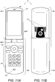
- FIG. 11 is a view showing an external configuration of the mobile communication terminal 20.
- the mobile communication terminal 20 is configured to be foldable by two movable housing sections (housings 20A and 20B), which are connected by a dual hinge DH.
- FIG. 11 shows a state in which the mobile communication terminal 20 is developed and also shows a style (form) that is used to employ the voice call function of the mobile communication terminal 20. More specifically, as shown in FIG. 11A , this is the style in which the mobile communication terminal 20 is developed in such a way that a speaker 242 for a receiver and a microphone 232 for a transmitter, both which are used at the speech communication, are flushed with each other.
- FIG.11A is a main surface of the mobile communication terminal 20.
- FIG.11B shows an external configuration of an outer surface side of the mobile communication terminal 20 at the time when the mobile communication terminal 20 is formed in open style.
- the speaker 242 for a receiver and a display screen are formed on the main surface of the housing 20A and that an operation section 232 including keys and buttons and the microphone 232 for a transmitter are formed on the main surface of the housing 20B.
- a main speaker 243 is formed on an outer surface of the housing 20A. Accordingly, in using the mobile communication terminal 20 in open style, the display section 241 is directed toward the user side (front side).
- the housing 20A is connected to the housing 20B to be rotatable in two directions by the dual hinge DH, thereby allowing the mobile communication terminal 20 to be held in multiple kinds of styles (forms). More specifically, the dual hinge DH connected to the housing 20A is rotatably held by hinge bases (right hinge base HB (R) and left hinge base HB (L)) fixed to the housing 20B, thereby the housing 20A is rotatably held within a predetermined range in a rotational direction about X axis as shown in FIG. 12 . The housing 20A is rotated about the X axis, thereby making it possible to the whole mobile communication terminal 20 to be opened and closed (developed ⁇ folded).
- hinge bases right hinge base HB (R) and left hinge base HB (L)
- both the dual hinge DH and the housing 20A are rotatably connected to each other. That is, the dual hinge HD has a movable portion where the housing 20A can be horizontally rotated about Z axis as a central axis as shown in FIG. 12 . As a result, the housing 20A is rotatably connected to the housing 20B within a predetermined range in a rotational direction about the Z axis as shown in FIG. 12 (for example, right and left 180°).
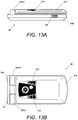
- FIG. 13 shows a style in which the housing 20A is rotated about the X axis from the open style shown Fig.11 in such a way that the main surface of the housing 20A and the main surface of the housing 20B are opposed to each other.
- This style shows the general folded state, and is hereinafter referred to as "close style.”
- FIG. 13A is a side view of the mobile communication terminal 20
- FIG. 13B is a plane view of the mobile communication terminal 20.
- FIG. 14 shows a style in which the housing 20A is rotated by 180 degrees about the Z axis from the open style shown FIG.11 .
- this style shows the state in which the housing 20A is inversed and is hereinafter referred to as "reverse-open style.”
- FIG. 14A is a plane view of the mobile communication terminal 20
- FIG. 14B is a side view of the mobile communication terminal 20.
- the main speaker 243 formed on the outer surface of the housing 20A is directed toward the user side (front side).
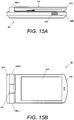
- FIG. 15 shows a style in which the housing 20A is rotated about the X axis from the reverse-open style shown FIG. 14 in such a way that the outer surface of the housing 20A and the main surface of the housing 20B are opposed to each other.
- This style shows the state in which the housing 20A in close style shown in FIG. 13 is reversed and the display section 241 is exposed.
- This style is one that is used to view a picture image and a moving image displayed on the display section 241 and is hereinafter referred to as "view style.”
- FIG. 15A is a side view of the mobile communication terminal 20
- FIG. 15B is a plane view of the mobile communication terminal 20.
- This view style is set as an appropriate style for the user to view the display on the display section 241. Accordingly, in using the mobile communication terminal 20 in view style, the display section 241 is directed toward the user side (front side).
- the mobile communication terminal 20 can offer the aforementioned four styles (forms) by changing the position and the direction of the movable housings connected by the dual hinge HD.
- the display screen (display section 241) of the mobile communication terminal 20 is exposed in the open style and view style
- the speech output device (main speaker 243) of the mobile communication terminal 20 is exposed in the reverse-open style and close style.
- a predetermined charging base (cradle, stand) is used in charging a battery as an operation power source for the mobile communication terminal 20 to be portably used or in driving the mobile communication terminal 20 with commercial power supply.
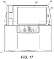
- the mobile communication terminal 20 is mounted on a cradle 21 as shown in FIG. 16 to perform charging.
- the cradle 21 shown in FIG. 16 is shaped to allow the mobile communication terminal 20 to be held even when the mobile communication terminal 20 is formed in any style.
- the mobile communication terminal 20 is formed in close style or view style (namely, folded state)
- the mobile communication terminal 20 is mounted on an upper surface of the cradle 21, thereby the terminal 20 is held as shown in FIG. 17 (FIG. 17 illustrates an example of the view style).
- the mobile communication terminal 20 is formed in open style or reverse-open style (namely, developed state)
- a portion of the housing 20B of the mobile communication terminal 20 is inserted into a notched portion ( FIG.16 ) formed on the front surface of the housing of the cradle 21, thereby the terminal 20 is held as shown in FIG. 18 (FIG. 18 illustrates an example of the reverse-open style).
- Connectors for power feeding are formed on both the upper surface of the cradle 21 and the notched portion thereof to make it possible to feed power to the mobile communication terminal 20 even if the mobile communication terminal 20 is formed in any style. These connectors are placed at a position where they are engaged with a connector portion 260 of the mounted mobile communication terminal 20.
- the surface of the mobile communication terminal 20, which corresponds to the front surface side of the cradle 21 (namely, the side opposing to the operating user) is a front surface.
- the main surface of the housing 20A with the display section 241 is the front surface.
- the outer surface of the housing 20A with the main speaker 243 is the front surface.
- the above-mentioned cradle 21 includes an outlet and a cord for commercial power to acquire commercial power.
- connection between these connectors is established by mounting the mobile communication terminal 20 on the cradle 21, acquired commercial power is sequentially supplied to the mobile communication terminal 20.
- FIG. 19 is a view showing both side surfaces of the mobile communication terminal 20 in open style
- FIG. 19A is a side view showing a side surface on the left facing the main surface
- FIG. 19B is a side view showing a side surface on the right facing the main surface.
- FIG. 20 is a block diagram showing the configuration of the mobile communication terminal 20.
- the mobile communication terminal 20 includes a control section 210, a communication control section 220, an input section 230, an output section 240, a style detection section 250, a connector section 260, a power supply section 270, a storage section 280, and the like.
- the control section 210 includes, for example, a CPU and a predetermined storage device (RAM) as a work area, and controls the respective sections of the mobile communication terminal 20 and executes each processing described later based on a predetermined operation program stored in the storage section 280. It should be noted that the below-described components of the mobile communication terminal 20 are connected to the control section 210, respectively, and data exchange among the respective components is assumed to be performed via the control section 210.
- RAM predetermined storage device
- the communication control section 220 includes, for instance, a predetermined radio communication circuit and performs radio communication through a predetermined antenna section 224.
- the communication control section 220 further includes a speech communication section 221, a data communication section 222, a broadcast reception section 223, and the like.
- the speech communication section 221 controls communication in connection with the telephone function (voice call function) of the mobile communication terminal 20.
- the speech communication section 221 controls the antenna section 224 to perform radio communication for a voice call via a telephone network such as a mobile communication network and to perform speech coding and decoding.
- the data communication section 222 controls communication in connection with the data communication function of the mobile communication terminal 20.
- supposing that data communication is performed via IP network such as the Internet
- the data communication section 222 controls the antenna section 224 to perform radio connection to the data communication network and data transmission and reception.
- the speech communication section 221 and data communication section 222 perform radio communication with a base station provided by a provider (so-called carrier) that offers mobile communication services to the mobile communication terminal 20.
- a provider so-called carrier
- the broadcast reception section 223 receives an airwave such as a television airwave and a radio airwave through the antenna section 224.
- the antenna section 224 is an antenna device that includes, for example, a predetermined antenna circuit, an antenna line, etc, and is provided for at least both the mobile communication and the television airwave reception.
- the input section 230 includes an operation section 231 and a microphone 232 for a transmitter, and functions as an interface for the user to input data to the mobile communication terminal 20.
- the operation section 231 includes predetermined buttons and keys (for example, character keys (ten keys), function buttons, directional keys, etc) ( FIG.11 ) and causes an input signal to be input to the control section 210 according to a user operation.
- predetermined buttons and keys for example, character keys (ten keys), function buttons, directional keys, etc.
- the microphone 232 for a transmitter is a microphone that is formed on the main surface of the housing 20B, and inputs user speech at the speech communication.
- the output section 240 includes a display section 241 and a speaker 242 for a receiver, a main speaker 243 and outputs various information.
- the display section 241 includes, for example, a liquid crystal display device, which is formed on the main surface of the housing 20A ( FIG. 11 ), and displays various screens relating to the functions of the mobile communication terminal 20.
- the display section 141 displays various screens necessary for operating the mobile communication terminal 20, and displays and outputs an image reproduced by executing an application to be described later.
- the speaker 242 for a receiver is a speaker, which is formed on the main surface of the housing 20A ( FIG. 11 ), and outputs a received sound at the speech communication.
- the main speaker 243 is a speaker, which is formed on the outer surface of the housing 20A ( FIG. 11 ), and outputs sound reproduced by executing an application to be described later in addition to a ring alert and the like.
- the main speaker 243 according to this embodiment is a stereo speaker that is composed of a pair of speaker devices. In this case, stereo reproduction is achieved by the pair of right and left speaker devices in the arrangement of the main speakers 243 shown in FIG. 11 . Accordingly, for reproducing the sound by the main speaker 243, the main speakers 243 are placed in the right and left directions as shown in FIG.11 , so that sound reproduction performance can be fully offered.
- the style detection section 250 includes, for example, a predetermined sensor device, and detects in which style the mobile communication terminal 20 is formed. More specifically, the style detection section 250 includes an open/close detection sensor 151 for detecting an open/close state of the mobile communication terminal 20, and a rotation detection sensor 152 for detecting a rotational angle about the Z-axis of the housing 20A, and detects the style of the mobile communication terminal 20 based on detection information of these sensors.
- the connector section 260 is a connector for making connection between the cradle 21 and this connector section and includes a receiving terminal.
- the connector section 260 is paired with a feeding connector provided in the cradle 21, and these connectors are connected to each other, so that power is received from the cradle 21 and supplied to the power supply section 270 via the connector section 260.
- the power supply section 270 includes a predetermined power circuit, a rechargeable buttery and the like, and charges the battery with the commercial power supplied via the connector section 260 connected to the cradle 21, and supplies power sent from the cradle 21 and power stored in the battery to each component of the mobile communication terminal 20.
- the storage section 280 includes a predetermined storage device such as a ROM, a flash memory, etc., and stores data necessary for executing each processing and data generated by execution of each processing, in addition to operation programs executed by the control section 110. Particularly, in this embodiment, the storage section 280 stores setting information S1 (to be specifically described) on the television reception function of the mobile communication terminal 20.
- the operation programs stored in the storage section 280 include an operation program for implementing each processing to be described later in addition to an arbitrary basic program that controls the base operation of the mobile communication terminal 20.
- the control section 210 executes these operation programs to thereby implement the below-described processing by the mobile communication terminal 20. Namely, execution of the operation programs stored in the storage section 280 causes the control section 210 to function as components as shown in FIG. 21 . As shown in the figure, the control section 210 functions as a connection detection section 211, a setting section 212, an application control section 213, an application execution section 214, a display control section 215, and a power control section 216.
- connection detection section 211 detects connection and disconnection between the mobile communication terminal 20 and the cradle 21 in cooperation with the power supply section 270.
- the setting section 112 performs processing on various settings (hereinafter referred to as "application setting") relating to the execution of application in cooperation with the operation section 231 and the storage section 280.
- the setting section 212 creates setting information S1 based on the user operation of the operation section 231, changes setting, and stores the result in the storage section 280. It should be noted that the setting section 212 creates various screens necessary for application setting and causes the result to be displayed on the display section 241. In this embodiment, the user sets which application should be automatically started up (automatic start-up setting) when the mobile communication terminal 20 is connected to the cradle 21.
- the application control section 213 causes the application execution section 214 to execute the application according to the style of the mobile communication terminal 20 and the setting information S1 in cooperation with the style detection section 250 and the storage section 280.
- the application execution section 214 is one that executes an application which is exactable by the mobile communication terminal 20.
- the application execution section 214 executes the application based on control made by the application control section 213 upon connection to the cradle 21.
- various functions except the voice call function as the basic function are implemented by the applications, and the control section 210 executes the program for each application to thereby perform the operation of each application.
- functions such as a television reception function, a radio reception function, an audio playback function (music playback function), a slide show function, a standby screen display function, etc., are implemented by the applications.
- the application programs for these functions are stored in the storage section 280 and the control section 210 executes these programs to thereby implement the respective applications.
- the display control section 215 controls the display screen of the display section 241 based on the application executed by the application execution section 214 and the style of the mobile communication terminal 20 detected by the style detection section 250 in corporation with the output section 240. Particularly, in this embodiment, the display control section 215 controls the screen display direction.
- the power control section 216 controls the power supply section 270 based on the setting information S1 to turn on and off the mobile communication terminal 20.
- the aforementioned functional configuration is logically implemented by the control section 210.
- the aforementioned functions are configured by a dedicated circuit such as an ASIC, so that these functions may be implemented by the physical configuration.
- execution condition information C1 which indicates an execution condition of each application, is prestored in the storage section 280.
- the execution conditions of applications which are started by the application automatic start-up setting by the user, are shown.
- FIG. 22 shows an example of execution condition information C1 stored in the storage section 280.
- the execution condition is chosen where connection to the cradle 21 is made such that the display screen faces front.
- the execution condition is chosen where the display screen faces front.
- the audio playback function that needs the sound output the execution condition is chosen where connection to the cradle 21 is made such that the main speaker faces front.
- the radio reception function that needs the sound output the execution condition is chosen where the main speaker faces front.
- an automatic start-up flag is added to the execution condition information C1.
- the flag corresponding to the relevant application is set (flag value 0 ⁇ 1).
- option setting information for each application is recorded in the execution condition information C1.
- the option setting information indicates an operation setting for automatically starting the application in which the automatic start-up flag is set, and setting is given thereto according to the application. For example, regarding the applications for the television reception function and the radio reception function, a channel that is received at the automatic start-up time is set. Moreover, regarding the applications for the audio playback function and the slide show function, storage locations for sound data and image data, which are reproduced at the automatic start-up time, are set.
- setting information S1 setting information
- the aforementioned components of the mobile communication terminal 20 are those necessary for implementing the present invention, and other components necessary for the basic functions as the mobile communication terminal and components necessary for various additional functions may be provided as required.
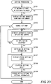
- setting processing which is executed when the mobile communication terminal 20 performs the application setting, will be explained with reference to a flow chart shown in FIG. 23 .
- This "setting processing” is started at the time when the user operates the operation section 231 to instruct the start of setting.
- step S2101 Yes
- the setting section 212 creates a "setting change confirmation screen" ( FIG. 24 ) to inquiry of the user about whether the set automatic start-up setting should be changed, and displays the created “setting change confirmation screen” on the displays section 241 (step S2102).
- the user operates the operation section 231 and selects "Yes” when he/she desires to change the setting, and selects "No” when he/she does not desire to change the setting.
- the setting section 212 determines whether the user will change setting based on the input from the operating section 231 (step S2103). When the user will not change the setting (step S2103: No), processing is directly ended.
- step S2103 When the user will change the setting (step S2103: Yes) or the automatic start-up application is not set (step S2101: No), the setting section 212 displays an "automatic start-up setting screen" for causing the user to select the automatic start-up application ( FIG. 24B ) on the display section 241 (step S2104).
- the setting section 212 displays an "option setting screen" for causing the user to set the option setting concerning the selected application ( FIG. 24C ) on the display section 241 (step S2107).
- the user operates the operation section 231 and inputs the option setting on the selected application.
- setting information S1 which indicates the application to be automatically started up that the user desires and the option setting, is stored in the storage section 280.
- the power supply source 270 notifies the control section 210 of the power supply.
- the connection detection section 211 detects that the mobile communication terminal 20 is connected to the cradle 21 based on the notification from the power supply section 270.
- the power control section 216 determines whether power of the mobile communication terminal 20 is turned off (step S2201). When power of the mobile communication terminal 20 is turned off (step S2201: Yes), the power control section 216 turns off power of the mobile communication terminal 20 (step S2202). In other words, when the power-off mobile communication terminal 20 is connected to the cradle 21, the mobile communication terminal 20 is automatically turned on.
- step S2203 When the application control section 213 gains access to the setting information S1 of the storage section 280 and determines whether an application automatic start-up setting is made, namely, there is a setting in which the automatic start-up flag is set (step S2203).
- step S2203 When the application automatic start-up setting is not made (step S2203: No), the power control section 216 instructs the power supply section 270 to turn off the mobile communication terminal 20. In this case, the power supply section 270 turns off power of the mobile communication terminal 20 in accordance with the instruction from the power control section 216 (step S2204), and processing is ended. Namely, when the mobile communication terminal 20 in which the application to be automatically started up is not set is connected to the cradle 21, power of the mobile communication terminal 20 is automatically turned off. In this case, the mobile communication terminal 20 performs charging to the battery of the power supply section 270.
- step S2203 when the application automatic start-up setting is made (step S2203: Yes), the application control section 213 recognizes to which application the automatic start-up setting is made based on the setting information S1 (step S2205).
- the application control section 213 inquiries of the style detection section 250 about in which style the mobile communication terminal 20 is currently formed.
- the style detection section 250 notifies the application control section 213 of information (hereinafter referred to as "style information") indicating the style of the mobile communication terminal 20 detected based on detection signals from the open/close detection sensors 151 and the rotation detection sensor 152 in response to the inquiry from the application control section 213.
- the application control section 213 obtains the style information from the style detection section 250, thereby recognizing the current style of the mobile communication terminal 20, namely, the style of the mobile communication terminal 20 connected to the cradle 21 (step S2206).
- the application control section 213 gains access to the execution condition information C1 of the storage section 280 and determines whether the style recognized in step S2206 matches the application execution condition recognized in step S2205 (step S2207).
- the application control section 213 judges the physical direction of the mobile communication terminal 20 connected to the cradle 21 in each style, and determines whether the relevant style matches the application execution condition set in the execution condition information C1 based on the judgment result.
- the display screen (display section 241) must be directed to the user (display screen faces front). Accordingly, in the case where the mobile communication terminal 20 and the cradle 21 are connected to each other so that the connector portion 260 of the mobile communication terminal 20 is engaged with the feeding connector of the cradle 21 (namely, connection is made in a normal connection direction), if the style of the mobile communication terminal 20 is an open style or view style, the execution condition is satisfied.
- the sound direction of the main speaker 243 must be directed to the user. Accordingly, in the case where the mobile communication terminal 20 and the cradle 21 are connected to each other in the normal connection direction, if the style of the mobile communication terminal 20 is a reverse-open style, the execution condition is satisfied.
- the application control section 213 determines whether the application to which the automatic start-up setting is made is executable based on the execution condition for each application and the current style of the mobile communication terminal 20.
- the application control section 213 determines whether the relevant application is one that provides the relevant screen display, namely, whether the display section 241 is used (step S2208).
- the display control section 215 decides a display direction based on the style of the mobile communication terminal 20 determined in step S2206, and controls the display section 241 to perform the screen display in the relevant display direction (step S2209).
- the execution condition of the application which provides the screen display
- the display control section 215 controls the display section 241 to obtain the display direction that matches the screen direction of the display section 241 in the current style of the mobile communication terminal 20.
- the application control section 213 instructs the application execution section 214 to start the execution of the relevant application after performing the display control. If the application to be executed is one that does not use the display section 241 (step S2208: No), the application control section 213 instructs the application execution section 214 to start the execution of the relevant application without performing the display control.
- the application execution section 214 executes the relevant application according to the instruction of the application control section 213 (step S2210), and processing is ended. At this time, the application execution section 214 gains access to the setting information S1 of the storage section 280 to perform an operation based on the option setting set in the relevant application.
- the application execution section 214 selects the relevant channel and starts the reception. Moreover, if reproducing data is set to the application that provides the audio playback function or the slide show function, the application execution section 214 gains access to the relevant data to start reproduction.
- the preset application is automatically executed upon connection to the cradle 21.
- the style of the communication terminal 20 connected to the cradle 21 is a style, which is suitable for executing the set application, the relevant application is executed, so that the application can be executed in an appropriate state.
- the user changes the style of the mobile communication terminal 20 upon connection to the cradle 21, thereby making it possible to select whether the set application should be automatically started up. Accordingly, it is possible to execute a desired operation without performing a precision operation.
- the style of the mobile communication terminal 20 may be brought into correspondence with each application as the application execution condition.
- execution condition information C2 as shown in FIG. 26A may be stored in the storage section 280.
- the application which is started up by the mobile communication terminal 20, is set for each holdable style. For instance, a "standby screen display application” is set regarding the "open style”, an “audio playback application” is set regarding the “reverse-open style”, and a “television reception application” is set regarding the "view style.” In addition, any application is not set to the "close style.”
- setting information S2 which represents application settings that indicate the respective application operation settings, is stored in the storage section 280.
- An example of the setting information S2 is shown by FIG. 26B .
- option setting information of each application is recorded. This option setting is the same as that shown in FIG. 22 . Accordingly, it is assumed that the same processing as the aforementioned "setting processing" is performed, thereby causing the user to carry out the option setting of each application.
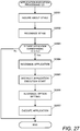
- the application control section 213 inquires of the style detection section 250 about the current style of the mobile communication terminal 20 (S2301).
- the style detection section 250 notifies the application control section 213 of style information indicating the style of the mobile communication terminal 20 detected based on the detection signal from the open/close detection sensor 151 and the rotation detection sensor 152 in response to the inquiry from the application control section 213.
- the application control section 213 recognizes the current style of the mobile communication terminal 20 based on the notification from the style detection section 250 (step S2302).
- the application control section 213 gains access to the execution condition information C2 of the storage section 280 and determines whether the application is made to correspond to the style recognized in step S2302 (step S2303).
- step S2303 When no application corresponding to the current style of the mobile communication terminal 20 is set (step S2303: No), processing is directly ended. In this case, the mobile communication terminal 20 performs charging to the battery of the power supply section 270.
- step S2303 when the application corresponding to the current style of the mobile communication terminal 20 is set (step S2303: Yes), the application control section 213 recognizes which application corresponds to the current style of the mobile communication terminal 20 (step S2304).
- the application control section 213 instructs the application execution section 214 to start execution of the relevant application (S2305).
- the application execution section 214 accesses the setting information S2 of the storage section 280 in accordance with the instruction from the application control section 213 and recognizes the option setting on the recognized application (step S2306).
- the application execution section 214 executes the application recognized in step S2304 based on the option setting recognized in step S2306 (step S2307) and processing is ended.
- the predetermined application which is appropriate for the style of the mobile communication terminal connected to the cradle 21, is automatically executed.
- the relevant application may be continuously executed on a priority basis.
- An example of the operation of the mobile communication terminal 20 in this case will be explained as follows.
- the application control section 213 determines whether the application is being executed by the application execution section 214 (step S2401).
- step S2401 When the application is not being executed by the application execution section 214 (step S2401: No), the application control section 213 further determines whether a user operation is made based on the presence or absence of the input signal from the operation section 231 (step S2402).
- step S2402 When the user operation is not made (step S2402: No), the application execution section 214 executes the application based on the setting information of the storage 280 and the style of the mobile communication terminal 20 (step S2403), and processing is ended. In this case, the same processing as the aforementioned "application execution processing (1)” and “application execution processing (2)” is executed, so that the application is executed according to the current style of the mobile communication terminal 20 and the setting contents. More specifically, recognition as to which application should be executed and determination as to whether the relevant application is executable are performed by the application control section 213, and the application execution section 214 executes the application according to the instruction from the application control section 213.
- step S2401 when the application is being executed when the mobile communication terminal 20 is connected to the cradle 21 (step S2401: Yes), the application execution section 214 continues to execute the relevant application (step S2404), and processing is ended.
- step S2402 when the user operation is made when the mobile communication terminal 20 is connected to the cradle 21 (step S2402: Yes), .the control section 210 performs the relevant operation (step S2405), and processing is ended.
- the execution of the relevant application is continued when the mobile communication terminal 20 where the application is running is connected to the cradle 21. Moreover, when the user operation is made, the operation is executed according to the relevant operation. Accordingly, even when the automatic start-up application is set, a higher priority can be given to the relevant operation than to the other operation. This prevents the application from being changed to the other application to which the automatic start-up setting is made even when the mobile communication terminal 20 is connected to the cradle 21 to be used with a stable power by the commercial power supply while, for example, the application is executed during the portable use of the mobile communication terminal 20.
- the appropriate application is automatically executed when the mobile communication terminal 20 is connected to the cradle 21, thereby making it possible to increase user convenience.
- the appropriate application is executed according to the style of the mobile communication terminal 20 connected to the cradle 20, so that the mobile communication terminal 20 can be operated to make full use of the performance of each function.
- either one of setting modes is selected.
- a plurality of setting modes may be set. In this case, for example, reception of a default channel set in the channel mode and acquisition of program guide data may be simultaneously executed when the mobile communication terminal 10 and the cradle 11 are connected to each other.
- default channel setting and timer setting are alternatively set. However, both settings may be taken. In this case, for instance, when the mobile communication terminal 10 and the cradle 11 are connected to each other, the operation can be performed so that the reception of the default channel is started, and thereafter the reception is changed to the channel where the reception start time zone is designated.
- program guide data which indicates the program being broadcasted at the time when the mobile communication terminal 10 and the cradle 10 are connected to each other, is acquired.
- program guide data relating to the other time zone may be acquired.
- program guide data is acquired at the time when the mobile communication terminal 10 and the cradle 11 are connected to each other.
- program guide data is acquired in advance and stored in the storage section 180. In this case, when program guide acquisition processing is started, a program guide is displayed based on program guide data stored in the storage section 180 and a program may be selected by the user.
- any setting contents may be included.
- the mobile communication terminal 10 has a recording function for a television broadcast, a setting relating to a recording operation for a television broadcast may be made.
- the reception start time zone is selected and designated.
- the present invention is not limited to this, and if the time when the reception is started can be designated, the reception start time zone may be designated in any method.
- the reception start time may be designated by user input of numeric values.
- designation of a reception end time may be included in setting information in addition to the reception start time.
- the reception control section 113 may stop the reception operation by the television reception section 123 when the time reaches the designated reception end time.
- the television reception operation is stopped at the time when the connection between the mobile communication terminal 10 and the cradle 11 is released.
- the television reception operation may be continued after the connection therebetween is released.
- the foldable mobile communication terminal 10 is mounted on the cradle 11 while being folded.
- the mobile communication terminal 10 can receive and output a television broadcast to be viewable by the user while being connected to the charging base (cradle)
- the mobile communication terminal 10 may be arbitrarily formed.
- the mobile communication terminal 10 may be mounted on the cradle 11 while being unfolded, or housings, which are not foldable (e.g., straight type or slide type), may be used.
- connection between the mobile communication terminal 10 and the cradle 11 is detected based on the connection between the connector section 160 of the mobile communication terminal 10 and the feeding connector of the cradle 11.
- any detection method may be used without being limited to this.
- connection between the mobile communication terminal 10 and the cradle 11 may be detected based on connection to a connector (e. g., data communication connector for connection to a personal computer, etc.,) excepting the connectors for power.
- a predetermined sensor is provided to the mobile communication terminal 10 or the cradle 11, thereby detection may be set that mobile communication terminal 10 is mounted on the cradle 11.
- any applications and setting contents shown in the second embodiment 2 are explained by way of example. However, if they relate to the operation executable by the mobile communication terminal 20, any applications and setting contents may be included.
- the application relating to the camera function may be automatically started up based on the style relevant to the direction of a lens placed on the housing of the mobile communication terminal 20.
- a web display application (browser) may be automatically started up in such a way to display a web page on a screen in landscape orientation.
- the application is automatically started up at the time when the mobile communication terminal 20 and the cradle 21 are connected to each other.
- the operation of the executed application may be finished at the time when connection between the mobile communication terminal 20 and the cradle 21 is released.
- the connection is released, power feeding from the cradle 21 is stopped and the mobile communication terminal 20 is driven by the battery.
- the execution of the application is ended, thereby making it possible to save battery consumption.
- the power supply section 270 notifies the connection detection section 211 of the stop of power feeding from the cradle 21, so that the connection detection section 211 can detect the release of the connection to the cradle 21.
- the execution of the application is continued.
- the application in execution is different from the application to which the automatic start-up setting is made, the application may be changed to the application to which the automatic stat-up setting is made.
- the double-axis foldable mobile communication terminal 20 is explained by way of example. However, if multiple styles (forms) of the mobile communication terminal 20 can be held by the housings, any type (e.g., slide type) may be used.
- arrangement of the housings and components (display section 241, main speaker 243, etc.,) used in executing the application are shown by way of example, and any arrangements may be possible. Namely, the execution condition information and setting information are prepared according to these arrangements, thereby making it possible to apply the present invention to various forms of the mobile communication terminals. Moreover, even if each of the execution condition information and setting information are preset by the manufacturer of the mobile communication terminal 20, they may be arbitrarily set by the user.
- the connection between the mobile communication terminal 10 and the cradle 11 is detected based on the connection between the connector section 260 of the mobile communication terminal 20 and the feeding connector of the cradle 21.
- any detection method may be used without being limited to this.
- the connection between the mobile communication terminal 20 and the cradle 21 may be detected based on connection to a connector (e. g., data communication connector for connection to a personal computer, etc.,) excepting the connectors for power.
- a predetermined sensor is provided to the mobile communication terminal 20 or the cradle 21, thereby detection may be set that mobile communication terminal 20 is mounted on the cradle 21.
- the present invention can be implemented by the mobile communication terminal having the configuration relating to the present invention in advance as in each of the above-explained embodiments.
- the present invention can be implemented by applying a program to the existing mobile communication terminal.
- the existing mobile communication terminal is allowed to function as the mobile communication terminals 10 and 20 of the aforementioned embodiments.
- the same operation program as the operation program executed by the control sections 110 and 210 of the aforementioned embodiments is installed to the storage device of the existing mobile communication terminal and the control device (CPU) of the mobile communication terminal executes this program, thereby allowing the device to function as the mobile communication terminal of the present invention.
- the form, which provides such the program is arbitrarily set.
- the program is distributed via a communication medium such as the Internet to make it possible to provide the program.
- the program is stored in a predetermined storage medium (e.g., memory card) to make it possible to provide the program.
Claims (13)
- Terminal de communication mobile (20), comprenant :deux boîtiers (20A, 20B) couplés entre eux,une section d'affichage (241) adaptée pour afficher une image,un haut-parleur (243) adapté pour émettre une voix, etune section d'exécution d'application (214) adaptée pour exécuter une application parmi une pluralité d'applications,caractérisé en ce queles deux boîtiers (20A, 20B) sont couplés entre eux par une double charnière (DH) de manière à pouvoir tourner dans deux directions, permettant ainsi au terminal de communication mobile (20) d'être agencé selon une pluralité de styles selon lesquels le terminal de communication mobile (20) est soit ouvert, soit fermé, en faisant tourner les deux boîtiers autour d'un premier axe de la double charnière (DH), et soit retourné, soit non retourné, en faisant tourner les deux boîtiers autour d'un deuxième axe de la double charnière (DH),et comprenant en outre :une section de stockage d'information de configuration (280) adaptée pour stocker de l'information de configuration des applications ;une section de détection de style (250) adaptée pour détecter un style parmi la pluralité de styles du terminal de communication mobile (20) selon lequel les deux boîtiers (20A, 20B) sont agencés l'un par rapport à l'autre ; etune section de contrôle d'application (213) adaptée pour contrôler l'exécution d'une application par la section d'exécution d'application sur base du style détecté par la section de détection de style (250) au moment où une connexion est établie avec un support (21),dans lequel la section de contrôle d'application comprend :une section de détermination de cible d'exécution adaptée pour déterminer si une application de cible d'exécution est configurée ou non dans l'information de configuration au moment où le terminal de communication mobile (20) et le support (21) sont connectés entre eux ; etune section d'acquisition d'information de style adaptée pour acquérir de l'information de style déterminée par la section de détection de style quand la section de détermination de cible d'exécution détermine que l'application de cible d'exécution est configurée,dans lequel, quand le style indiqué par l'information de style acquise par la section d'acquisition d'information de style est un style correspondant à l'application configurée comme cible d'exécution, la section d'exécution d'application reçoit une commande d'exécution de l'application.
- Terminal de communication mobile selon la revendication 1, dans lequel la section de contrôle d'application (213) est en outre adaptée pour commander à la section d'exécution d'application (214) d'exécuter une application en utilisant la section d'affichage (241) quand le style détecté par la section de détection de style (250) est un style selon lequel la section d'affichage (241) est tournée vers l'avant.
- Terminal de communication mobile selon la revendication 1, dans lequel la section de contrôle d'application (213) est en outre adaptée pour commander à la section d'exécution d'application (214) d'exécuter une application en utilisant la section d'affichage (241) quand le style détecté par la section de détection de style (250) est un style selon lequel la section d'affichage (241) du terminal de communication mobile est tournée vers l'avant et est repliée.
- Terminal de communication mobile selon la revendication 1, comprenant en outre :une section de contrôle d'affichage adaptée pour contrôler la section d'affichage (241) sur base du style détecté par la section de détection de style (250) quand la section d'exécution d'application (214) exécute une application en utilisant la section d'affichage (241).
- Terminal de communication mobile selon la revendication 4, dans lequel la section de contrôle d'affichage est en outre adaptée pour contrôler la section d'affichage (241) de manière à obtenir une orientation d'affichage panoramique sur base du fait que le style détecté par la section de détection de style (250) est un état replié tel que la section d'affichage (241) du terminal de communication mobile est tournée vers l'avant.
- Terminal de communication mobile selon la revendication 1, dans lequel la section de contrôle d'application (213) est en outre adaptée pour commander à la section d'exécution d'application (214) d'exécuter une application en utilisant le haut-parleur (243) quand le style détecté par la section de détection de style est un état de rotation où le haut-parleur (243) est tourné vers l'avant.
- Terminal de communication mobile selon la revendication 1,
dans lequel la section de stockage d'information de configuration (280) est en outre adaptée pour stocker de l'information de configuration dans laquelle le style d'agencement des deux boîtiers et une application en cours d'exécution sont mis en correspondance entre eux, et
dans lequel la section de contrôle d'application (213) est en outre adaptée pour commander à la section d'exécution d'application (214) d'exécuter une application correspondant au style détecté par la section de détection de style (250). - Terminal de communication mobile selon la revendication 1, dans lequel la section de contrôle d'application (213) est en outre adaptée pour commander à la section d'exécution d'application (214) d'arrêter l'exécution de l'application au moment où la connexion entre le terminal de communication mobile (20) et le support (21) est désengagée.
- Terminal de communication mobile selon la revendication 1, dans lequel le terminal de communication mobile (20) et le support (21) sont connectés entre eux, la section de contrôle d'application (213) détermine si la section d'exécution d'application (214) exécute ou non une application, et quand la section d'exécution d'application (214) exécute l'application, la section de contrôle d'application (213) commande à la section d'exécution d'application (214) de continuer à exécuter l'application.
- Terminal de communication mobile selon la revendication 9, dans lequel, quand le terminal de communication mobile (20) ne met en oeuvre aucune opération au moment où le terminal de communication mobile (20) et le support (21) sont connectés entre eux, la section de contrôle d'application (213) détermine si la section d'exécution d'application (214) exécute ou non une application.
- Terminal de communication mobile selon la revendication 1, comprenant en outre :une section de contrôle d'alimentation (216) adaptée pour déterminer si l'alimentation du terminal de communication mobile (20) est désactivée ou non au moment où le terminal de communication mobile (20) et le support (21) sont connectés entre eux, et pour activer l'alimentation du terminal de communication mobile (20) quand la puissance du terminal de communication mobile (20) est désactivée,dans lequel la section de contrôle d'application (213) est en outre adaptée pour contrôler la section d'exécution d'application (214) quand l'alimentation du terminal de communication mobile (20) est désactivée par la section de contrôle d'alimentation (216).
- Terminal de communication mobile selon la revendication 11, dans lequel la section de contrôle d'alimentation (216) est en outre adaptée pour désactiver l'alimentation du terminal de communication mobile (20) quand la section d'exécution d'application (214) n'est pas contrôlée par la section de contrôle d'application (213).
- Programme commandant un ordinateur, qui contrôle un terminal de communication mobile comportant deux boîtiers (20A, 20B) couplés entre eux par une double charnière (DH) de manière à pouvoir tourner dans deux directions, permettant ainsi au terminal de communication mobile (20) d'être agencé selon une pluralité de styles selon lesquels le terminal de communication mobile (20) est soit ouvert, soit fermé, en faisant tourner les deux boîtiers autour d'un premier axe de la double charnière (DH), et soit retourné, soit non retourné, en faisant tourner les deux boîtiers autour d'un deuxième axe de la double charnière (DH), une section d'affichage (241) adaptée pour afficher une image, un haut-parleur (243) adapté pour émettre une voix, et une section d'exécution d'application (214) adaptée pour exécuter une application parmi une pluralité d'applications, afin d'exécuter les fonctions suivantes :stockage d'information de configuration des applications ;détection d'un style parmi la pluralité de styles du terminal de communication mobile (20) selon lequel les deux boîtiers (20A, 20B) sont agencés l'un par rapport à l'autre ;détermination du fait qu'une application de cible d'exécution est configurée ou non dans l'information de configuration au moment où le terminal de communication mobile (20) et le support (21) sont connectés entre eux ;acquisition d'information de style déterminée par le style détecté quand l'application de cible d'exécution est déterminée comme étant configurée ; etexécution de l'application par la section d'exécution d'application (214) si le style indiqué par l'information de style acquise est un style correspondant à l'application configurée comme cible d'exécution.
Applications Claiming Priority (3)
| Application Number | Priority Date | Filing Date | Title |
|---|---|---|---|
| JP2005226327A JP4198139B2 (ja) | 2005-08-04 | 2005-08-04 | 移動体通信端末、および、プログラム |
| JP2005233571A JP4313792B2 (ja) | 2005-08-11 | 2005-08-11 | 移動体通信端末、および、プログラム |
| EP06015727.8A EP1750421B1 (fr) | 2005-08-04 | 2006-07-27 | Exécution d'application dans un terminal de communication mobile lors du placement de ce terminal dans un chargeur |
Related Parent Applications (3)
| Application Number | Title | Priority Date | Filing Date |
|---|---|---|---|
| EP06015727.8 Division | 2006-07-27 | ||
| EP06015727.8A Division EP1750421B1 (fr) | 2005-08-04 | 2006-07-27 | Exécution d'application dans un terminal de communication mobile lors du placement de ce terminal dans un chargeur |
| EP06015727.8A Division-Into EP1750421B1 (fr) | 2005-08-04 | 2006-07-27 | Exécution d'application dans un terminal de communication mobile lors du placement de ce terminal dans un chargeur |
Publications (2)
| Publication Number | Publication Date |
|---|---|
| EP2372983A1 EP2372983A1 (fr) | 2011-10-05 |
| EP2372983B1 true EP2372983B1 (fr) | 2017-08-30 |
Family
ID=37307402
Family Applications (2)
| Application Number | Title | Priority Date | Filing Date |
|---|---|---|---|
| EP10191495.0A Expired - Fee Related EP2372983B1 (fr) | 2005-08-04 | 2006-07-27 | Exécution d'application dans un terminal de communication mobile lors du placement de ce terminal dans un chargeur |
| EP06015727.8A Expired - Fee Related EP1750421B1 (fr) | 2005-08-04 | 2006-07-27 | Exécution d'application dans un terminal de communication mobile lors du placement de ce terminal dans un chargeur |
Family Applications After (1)
| Application Number | Title | Priority Date | Filing Date |
|---|---|---|---|
| EP06015727.8A Expired - Fee Related EP1750421B1 (fr) | 2005-08-04 | 2006-07-27 | Exécution d'application dans un terminal de communication mobile lors du placement de ce terminal dans un chargeur |
Country Status (2)
| Country | Link |
|---|---|
| US (1) | US7805163B2 (fr) |
| EP (2) | EP2372983B1 (fr) |
Families Citing this family (11)
| Publication number | Priority date | Publication date | Assignee | Title |
|---|---|---|---|---|
| KR101141616B1 (ko) * | 2006-11-20 | 2012-05-17 | 엘지전자 주식회사 | 미들릿 실행 단말기 및 그 방법 |
| JP4483921B2 (ja) * | 2007-09-25 | 2010-06-16 | 株式会社カシオ日立モバイルコミュニケーションズ | 通信システム |
| KR101366859B1 (ko) * | 2007-10-31 | 2014-02-21 | 엘지전자 주식회사 | 휴대 단말기 |
| WO2009084088A1 (fr) * | 2007-12-27 | 2009-07-09 | Fujitsu Limited | Dispositif portable et son procédé de commande d'affichage |
| JP5337448B2 (ja) * | 2008-10-28 | 2013-11-06 | 京セラ株式会社 | 携帯通信装置の充電システム |
| KR20110011975A (ko) * | 2009-07-29 | 2011-02-09 | 삼성전자주식회사 | 방송수신장치 및 그 디스플레이 방법 |
| KR101736863B1 (ko) * | 2010-06-30 | 2017-05-17 | 엘지전자 주식회사 | 이동 단말기 및 이를 구비하는 단말 시스템 |
| EP2533401B1 (fr) * | 2011-05-26 | 2013-11-27 | LG Electronics Inc. | Terminal mobile et son procédé de contrôle |
| US10133329B2 (en) | 2012-11-19 | 2018-11-20 | Qualcomm Incorporated | Sequential feature computation for power efficient classification |
| US11163289B2 (en) | 2017-02-24 | 2021-11-02 | Sharp Kabushiki Kaisha | Control device, terminal device, cradle, notification system, control method, and storage medium |
| WO2018154946A1 (fr) | 2017-02-24 | 2018-08-30 | シャープ株式会社 | Dispositif de commande, dispositif terminal, station d'accueil, système de notification, procédé de commande et programme de commande |
Family Cites Families (34)
| Publication number | Priority date | Publication date | Assignee | Title |
|---|---|---|---|---|
| US5536930A (en) * | 1992-06-03 | 1996-07-16 | Symbol Technologies, Inc. | Apparatus and method for sensing positional orientations of a portable terminal |
| US5758267A (en) * | 1996-07-08 | 1998-05-26 | Motorola, Inc. | Method and apparatus for orientation controlled parameter selection |
| JP3919263B2 (ja) | 1996-09-02 | 2007-05-23 | キヤノン株式会社 | 無線受信装置及び制御方法 |
| JPH11103279A (ja) | 1997-09-29 | 1999-04-13 | Toshiba Corp | 受信装置及び中継装置 |
| US6266539B1 (en) * | 1998-06-12 | 2001-07-24 | Cisco Technology, Inc. | Telephone docking station for personal digital assistant |
| US6411828B1 (en) * | 1999-03-19 | 2002-06-25 | Ericsson Inc. | Communications devices and methods that operate according to communications device orientations determined by reference to gravitational sensors |
| JP2001068312A (ja) | 1999-08-26 | 2001-03-16 | Fuji Elelctrochem Co Ltd | 電波吸収熱伝導シート |
| JP2002199062A (ja) | 2000-12-25 | 2002-07-12 | Hitachi Ltd | 携帯端末装置 |
| US7103760B1 (en) | 2001-07-16 | 2006-09-05 | Billington Corey A | Embedded electronic device connectivity system |
| WO2003026153A1 (fr) * | 2001-09-20 | 2003-03-27 | Exo-Brain, Inc. | Organe d'entree-sortie a port telephonique universel |
| US7159194B2 (en) * | 2001-11-30 | 2007-01-02 | Palm, Inc. | Orientation dependent functionality of an electronic device |
| JP3945241B2 (ja) | 2001-12-14 | 2007-07-18 | 松下電器産業株式会社 | テレビ付き携帯通信装置とこれを用いた情報配信システム |
| US7395041B2 (en) | 2001-12-31 | 2008-07-01 | Nokia Corporation | Mobile phone and method of updating radio channel settings |
| US6957090B2 (en) * | 2002-03-08 | 2005-10-18 | Kyocera Wireless Corp. | Hands-free car kit |
| DE10211002A1 (de) * | 2002-03-13 | 2003-09-25 | Philips Intellectual Property | Tragbares elektronisches Gerät mit Mitteln zur Registrierung der räumlichen Lage |
| JP2003309791A (ja) * | 2002-04-15 | 2003-10-31 | Toshiba Corp | 記憶装置及びそのデータ書込み制御方法 |
| US7257430B2 (en) * | 2002-05-11 | 2007-08-14 | Motorola, Inc. | Self configuring multiple element portable electronic device |
| KR100678204B1 (ko) * | 2002-09-17 | 2007-02-01 | 삼성전자주식회사 | 휴대단말기의 모드에 따른 영상 및 데이터 표시장치 및 방법 |
| JP4341267B2 (ja) | 2003-03-18 | 2009-10-07 | カシオ計算機株式会社 | 携帯電子機器システム、携帯電子機器、携帯電子機器の制御方法及びプログラム |
| JP4355849B2 (ja) | 2003-06-06 | 2009-11-04 | カシオ計算機株式会社 | 記録装置、記録装置の電源制御方法及びプログラム |
| JP2005043676A (ja) * | 2003-07-22 | 2005-02-17 | Sony Corp | 情報端末装置 |
| WO2005013586A1 (fr) | 2003-07-31 | 2005-02-10 | Vodafone K.K. | Dispositif terminal de communication mobile |
| JP3835441B2 (ja) | 2003-08-26 | 2006-10-18 | ソニー株式会社 | 携帯型電子機器 |
| JP4576812B2 (ja) | 2003-08-27 | 2010-11-10 | 日本電気株式会社 | 携帯情報端末装置用ホルダ、携帯情報端末装置及びプログラム |
| WO2005022913A1 (fr) | 2003-08-29 | 2005-03-10 | Access Co., Ltd. | Systeme de notification pour scene d'emission de diffusion |
| JP4656481B2 (ja) | 2003-09-08 | 2011-03-23 | 日本テレビ放送網株式会社 | 録画再生装置、受信装置及び制御方法と制御プログラム |
| JP2005101879A (ja) | 2003-09-25 | 2005-04-14 | Sharp Corp | 携帯電話装置 |
| JP4622223B2 (ja) * | 2003-09-30 | 2011-02-02 | カシオ計算機株式会社 | 携帯電話機 |
| JP2005123754A (ja) | 2003-10-15 | 2005-05-12 | Nec Corp | 放送通信複合端末 |
| JP2005140686A (ja) | 2003-11-07 | 2005-06-02 | Casio Comput Co Ltd | 携帯電子機器システム、携帯電子機器及びプログラム |
| JP2005286430A (ja) * | 2004-03-26 | 2005-10-13 | Sharp Corp | 携帯機器 |
| JP4570391B2 (ja) | 2004-05-11 | 2010-10-27 | 京セラ株式会社 | 放送受信記録再生装置 |
| JP2006108920A (ja) | 2004-10-01 | 2006-04-20 | Toshiba Corp | 車載端末装置 |
| JP4433979B2 (ja) | 2004-10-28 | 2010-03-17 | 船井電機株式会社 | 放送録画再生装置、および、放送録画再生表示装置 |
-
2006
- 2006-07-27 EP EP10191495.0A patent/EP2372983B1/fr not_active Expired - Fee Related
- 2006-07-27 EP EP06015727.8A patent/EP1750421B1/fr not_active Expired - Fee Related
- 2006-08-02 US US11/497,901 patent/US7805163B2/en active Active
Non-Patent Citations (1)
| Title |
|---|
| None * |
Also Published As
| Publication number | Publication date |
|---|---|
| US20070032262A1 (en) | 2007-02-08 |
| EP2372983A1 (fr) | 2011-10-05 |
| US7805163B2 (en) | 2010-09-28 |
| EP1750421A2 (fr) | 2007-02-07 |
| EP1750421A3 (fr) | 2010-05-05 |
| EP1750421B1 (fr) | 2017-11-08 |
Similar Documents
| Publication | Publication Date | Title |
|---|---|---|
| EP2372983B1 (fr) | Exécution d'application dans un terminal de communication mobile lors du placement de ce terminal dans un chargeur | |
| JP5151976B2 (ja) | 携帯電話機 | |
| US8433370B2 (en) | Mobile terminal and controlling method thereof | |
| RU2452123C2 (ru) | Тонкая активная крышка камеры для электронного устройства | |
| US8457690B2 (en) | Multi-housing mobile terminal | |
| US20070286596A1 (en) | Method and system for adjusting camera settings in a camera equipped mobile radio terminal | |
| JP4313792B2 (ja) | 移動体通信端末、および、プログラム | |
| JP4399677B1 (ja) | 端末装置及びプログラム | |
| JP4497194B2 (ja) | 携帯端末装置及びプログラム | |
| JP4538434B2 (ja) | 携帯端末装置及びプログラム | |
| CN1909701B (zh) | 移动通信终端及程序 | |
| JP4889353B2 (ja) | 携帯通信端末 | |
| JP4728880B2 (ja) | 放送記録装置及びプログラム | |
| KR100767947B1 (ko) | 이동통신단말 및 컴퓨터-판독가능 기록매체 | |
| JP4476198B2 (ja) | 端末装置 | |
| JP2006078750A (ja) | 携帯型情報処理装置、情報提示方法および情報提示プログラム | |
| JP5073374B2 (ja) | 情報処理装置、情報処理装置の制御方法、制御プログラム、および、記録媒体 | |
| JP2007116524A (ja) | 通信装置及び該通信装置における放送内容記憶方法 | |
| KR100735229B1 (ko) | 대기 화면에 디지털 멀티미디어 방송을 표시하는 방법 및이를 위한 단말기 | |
| JP2005079607A (ja) | 携帯電話機器 | |
| JP4978349B2 (ja) | 情報処理装置 | |
| JP2002281121A (ja) | コミュニケーション機能を持つ民生機器 | |
| JP2002281124A (ja) | 携帯電話サービスを受けることが可能な通信機器 | |
| JP4778356B2 (ja) | 携帯端末装置 | |
| JP2010098511A (ja) | 携帯端末装置及びプログラム |
Legal Events
| Date | Code | Title | Description |
|---|---|---|---|
| PUAI | Public reference made under article 153(3) epc to a published international application that has entered the european phase |
Free format text: ORIGINAL CODE: 0009012 |
|
| AC | Divisional application: reference to earlier application |
Ref document number: 1750421 Country of ref document: EP Kind code of ref document: P |
|
| AK | Designated contracting states |
Kind code of ref document: A1 Designated state(s): DE FR GB |
|
| 17P | Request for examination filed |
Effective date: 20120405 |
|
| 17Q | First examination report despatched |
Effective date: 20120705 |
|
| RAP1 | Party data changed (applicant data changed or rights of an application transferred) |
Owner name: NEC CORPORATION |
|
| RAP1 | Party data changed (applicant data changed or rights of an application transferred) |
Owner name: LENOVO INNOVATIONS LIMITED (HONG KONG) |
|
| GRAP | Despatch of communication of intention to grant a patent |
Free format text: ORIGINAL CODE: EPIDOSNIGR1 |
|
| RIC1 | Information provided on ipc code assigned before grant |
Ipc: H04N 5/445 20110101ALN20170403BHEP Ipc: H04M 1/02 20060101ALN20170403BHEP Ipc: H04M 1/04 20060101AFI20170403BHEP Ipc: H04N 21/442 20110101ALN20170403BHEP Ipc: H04N 21/414 20110101ALN20170403BHEP Ipc: H04M 1/725 20060101ALN20170403BHEP |
|
| INTG | Intention to grant announced |
Effective date: 20170424 |
|
| RIN1 | Information on inventor provided before grant (corrected) |
Inventor name: NAMATAME, SHIGERU Inventor name: GOTO, YOSHIHIRO |
|
| GRAS | Grant fee paid |
Free format text: ORIGINAL CODE: EPIDOSNIGR3 |
|
| GRAA | (expected) grant |
Free format text: ORIGINAL CODE: 0009210 |
|
| AC | Divisional application: reference to earlier application |
Ref document number: 1750421 Country of ref document: EP Kind code of ref document: P |
|
| AK | Designated contracting states |
Kind code of ref document: B1 Designated state(s): DE FR GB |
|
| REG | Reference to a national code |
Ref country code: GB Ref legal event code: FG4D |
|
| REG | Reference to a national code |
Ref country code: DE Ref legal event code: R096 Ref document number: 602006053500 Country of ref document: DE |
|
| REG | Reference to a national code |
Ref country code: DE Ref legal event code: R097 Ref document number: 602006053500 Country of ref document: DE |
|
| PLBE | No opposition filed within time limit |
Free format text: ORIGINAL CODE: 0009261 |
|
| STAA | Information on the status of an ep patent application or granted ep patent |
Free format text: STATUS: NO OPPOSITION FILED WITHIN TIME LIMIT |
|
| 26N | No opposition filed |
Effective date: 20180531 |
|
| PG25 | Lapsed in a contracting state [announced via postgrant information from national office to epo] |
Ref country code: FR Free format text: LAPSE BECAUSE OF NON-PAYMENT OF DUE FEES Effective date: 20180731 |
|
| PGFP | Annual fee paid to national office [announced via postgrant information from national office to epo] |
Ref country code: DE Payment date: 20190731 Year of fee payment: 14 |
|
| PGFP | Annual fee paid to national office [announced via postgrant information from national office to epo] |
Ref country code: GB Payment date: 20190729 Year of fee payment: 14 |
|
| REG | Reference to a national code |
Ref country code: DE Ref legal event code: R119 Ref document number: 602006053500 Country of ref document: DE |
|
| GBPC | Gb: european patent ceased through non-payment of renewal fee |
Effective date: 20200727 |
|
| PG25 | Lapsed in a contracting state [announced via postgrant information from national office to epo] |
Ref country code: GB Free format text: LAPSE BECAUSE OF NON-PAYMENT OF DUE FEES Effective date: 20200727 |
|
| PG25 | Lapsed in a contracting state [announced via postgrant information from national office to epo] |
Ref country code: DE Free format text: LAPSE BECAUSE OF NON-PAYMENT OF DUE FEES Effective date: 20210202 |