EP2372848B1 - Dispositif et procédé de mise en place de câbles avec des manchons - Google Patents
Dispositif et procédé de mise en place de câbles avec des manchons Download PDFInfo
- Publication number
- EP2372848B1 EP2372848B1 EP11157888A EP11157888A EP2372848B1 EP 2372848 B1 EP2372848 B1 EP 2372848B1 EP 11157888 A EP11157888 A EP 11157888A EP 11157888 A EP11157888 A EP 11157888A EP 2372848 B1 EP2372848 B1 EP 2372848B1
- Authority
- EP
- European Patent Office
- Prior art keywords
- needle
- cable
- pushing
- equipping
- jaws
- Prior art date
- Legal status (The legal status is an assumption and is not a legal conclusion. Google has not performed a legal analysis and makes no representation as to the accuracy of the status listed.)
- Active
Links
- 238000000034 method Methods 0.000 title claims description 20
- 230000033001 locomotion Effects 0.000 claims description 54
- 238000012546 transfer Methods 0.000 claims description 7
- 238000006073 displacement reaction Methods 0.000 claims 2
- 238000003780 insertion Methods 0.000 description 5
- 230000037431 insertion Effects 0.000 description 5
- 238000012545 processing Methods 0.000 description 5
- 238000013459 approach Methods 0.000 description 3
- 238000013461 design Methods 0.000 description 2
- 230000007704 transition Effects 0.000 description 2
- 238000005452 bending Methods 0.000 description 1
- 230000006835 compression Effects 0.000 description 1
- 238000007906 compression Methods 0.000 description 1
- 230000001419 dependent effect Effects 0.000 description 1
- 238000011161 development Methods 0.000 description 1
- 230000018109 developmental process Effects 0.000 description 1
- 239000006185 dispersion Substances 0.000 description 1
- 238000005516 engineering process Methods 0.000 description 1
- 238000009413 insulation Methods 0.000 description 1
- 238000004519 manufacturing process Methods 0.000 description 1
- 239000000463 material Substances 0.000 description 1
- 239000002184 metal Substances 0.000 description 1
- 229920001296 polysiloxane Polymers 0.000 description 1
- 238000007789 sealing Methods 0.000 description 1
- 238000000926 separation method Methods 0.000 description 1
Images


Classifications
-
- H—ELECTRICITY
- H01—ELECTRIC ELEMENTS
- H01R—ELECTRICALLY-CONDUCTIVE CONNECTIONS; STRUCTURAL ASSOCIATIONS OF A PLURALITY OF MUTUALLY-INSULATED ELECTRICAL CONNECTING ELEMENTS; COUPLING DEVICES; CURRENT COLLECTORS
- H01R43/00—Apparatus or processes specially adapted for manufacturing, assembling, maintaining, or repairing of line connectors or current collectors or for joining electric conductors
- H01R43/005—Apparatus or processes specially adapted for manufacturing, assembling, maintaining, or repairing of line connectors or current collectors or for joining electric conductors for making dustproof, splashproof, drip-proof, waterproof, or flameproof connection, coupling, or casing
-
- H—ELECTRICITY
- H01—ELECTRIC ELEMENTS
- H01R—ELECTRICALLY-CONDUCTIVE CONNECTIONS; STRUCTURAL ASSOCIATIONS OF A PLURALITY OF MUTUALLY-INSULATED ELECTRICAL CONNECTING ELEMENTS; COUPLING DEVICES; CURRENT COLLECTORS
- H01R43/00—Apparatus or processes specially adapted for manufacturing, assembling, maintaining, or repairing of line connectors or current collectors or for joining electric conductors
- H01R43/28—Apparatus or processes specially adapted for manufacturing, assembling, maintaining, or repairing of line connectors or current collectors or for joining electric conductors for wire processing before connecting to contact members, not provided for in groups H01R43/02 - H01R43/26
-
- Y—GENERAL TAGGING OF NEW TECHNOLOGICAL DEVELOPMENTS; GENERAL TAGGING OF CROSS-SECTIONAL TECHNOLOGIES SPANNING OVER SEVERAL SECTIONS OF THE IPC; TECHNICAL SUBJECTS COVERED BY FORMER USPC CROSS-REFERENCE ART COLLECTIONS [XRACs] AND DIGESTS
- Y10—TECHNICAL SUBJECTS COVERED BY FORMER USPC
- Y10T—TECHNICAL SUBJECTS COVERED BY FORMER US CLASSIFICATION
- Y10T29/00—Metal working
- Y10T29/49—Method of mechanical manufacture
- Y10T29/49826—Assembling or joining
- Y10T29/49863—Assembling or joining with prestressing of part
- Y10T29/4987—Elastic joining of parts
-
- Y—GENERAL TAGGING OF NEW TECHNOLOGICAL DEVELOPMENTS; GENERAL TAGGING OF CROSS-SECTIONAL TECHNOLOGIES SPANNING OVER SEVERAL SECTIONS OF THE IPC; TECHNICAL SUBJECTS COVERED BY FORMER USPC CROSS-REFERENCE ART COLLECTIONS [XRACs] AND DIGESTS
- Y10—TECHNICAL SUBJECTS COVERED BY FORMER USPC
- Y10T—TECHNICAL SUBJECTS COVERED BY FORMER US CLASSIFICATION
- Y10T29/00—Metal working
- Y10T29/53—Means to assemble or disassemble
- Y10T29/53657—Means to assemble or disassemble to apply or remove a resilient article [e.g., tube, sleeve, etc.]
-
- Y—GENERAL TAGGING OF NEW TECHNOLOGICAL DEVELOPMENTS; GENERAL TAGGING OF CROSS-SECTIONAL TECHNOLOGIES SPANNING OVER SEVERAL SECTIONS OF THE IPC; TECHNICAL SUBJECTS COVERED BY FORMER USPC CROSS-REFERENCE ART COLLECTIONS [XRACs] AND DIGESTS
- Y10—TECHNICAL SUBJECTS COVERED BY FORMER USPC
- Y10T—TECHNICAL SUBJECTS COVERED BY FORMER US CLASSIFICATION
- Y10T29/00—Metal working
- Y10T29/53—Means to assemble or disassemble
- Y10T29/53709—Overedge assembling means
- Y10T29/53787—Binding or covering
-
- Y—GENERAL TAGGING OF NEW TECHNOLOGICAL DEVELOPMENTS; GENERAL TAGGING OF CROSS-SECTIONAL TECHNOLOGIES SPANNING OVER SEVERAL SECTIONS OF THE IPC; TECHNICAL SUBJECTS COVERED BY FORMER USPC CROSS-REFERENCE ART COLLECTIONS [XRACs] AND DIGESTS
- Y10—TECHNICAL SUBJECTS COVERED BY FORMER USPC
- Y10T—TECHNICAL SUBJECTS COVERED BY FORMER US CLASSIFICATION
- Y10T29/00—Metal working
- Y10T29/53—Means to assemble or disassemble
- Y10T29/53796—Puller or pusher means, contained force multiplying operator
- Y10T29/53839—Puller or pusher means, contained force multiplying operator having percussion or explosive operator
- Y10T29/53843—Tube, sleeve, or ferrule inserting or removing
Definitions
- the invention relates to an apparatus and a method for assembling cables with spouts, i. It is about applications in the field of cable processing or assembly.
- the device and method can also be applied to other elastic cable elements.
- Spouts are silicone or similar material sealing elements typically used to seal plug housings or, for example, electrical appliances. For this purpose, a spout is first fitted to a stripped cable and then a metal contact is crimped. The contact is designed to hold the grommet to the cable.
- fully automatic grommets are used in wire processing machines that automatically bring the stripped cable to and from the grommet device.
- Semi-automatic grommets are typically used as desktop devices, with the cable having to be manually inserted into a gripper of the grommet device.
- a needle-shaped guide member sits in the interior of the hollow cylinder, that a tapered end of the needle protrudes from an opening of the hollow cylinder, which points in the direction of spout. So it is the hollow cylinder is inserted together with the inner-seated needle in the spout, while the pressure body as mentioned counterpressure exerts. Due to the fact that the needle tapers, solidarity insertion of hollow cylinder and needle is gentle. After the hollow cylinder has been inserted into the spout, the needle is withdrawn to allow space inside the hollow cylinder create for the insertion of a cable end. After the cable end has been inserted, the hollow cylinder is pulled back and thus passed the spout of the hollow cylinder on the cable.
- EP-B1-0 626 738 An easier to maintain and faster-working grommet is out EP-B1-0 626 738 known.
- EP-B1-0 626 738 suggests a Tüllenbe conductedungshold, in which a spout is applied during the singulation of a conveyor rail on a mandrel and pushed on this mandrel from a smaller to a larger diameter, so as to expand the spout. After the mandrel has been pivoted into the correct position, a two-part expansion sleeve and also a two-part scraper surrounds the spout. By a relative movement of the scraper, the spout is pushed onto the expansion sleeve.
- the actual placement process is carried out by moving the expansion sleeve with the spout and the wiper together over the cable.
- the scraper stops before the expansion sleeve has completed its movement, which causes the stripping of the grommet on the cable.
- EP-B1-1 022 821 is another device for Tüllenbe Publishedung known.
- the spout after a separation on a tubular, applied one-piece expansion sleeve.
- the grommet is not held in addition to the pivoting in the horizontal placement position.
- the assembly After embracing the spout with a two-part wiper, the assembly is done by moving over the cable with subsequent retraction of the expansion sleeve.
- the invention aims to remedy this situation.
- the invention as characterized in the main claims, solves the problem of a simple, safe and fast assembly of cables with elastic cable elements, e.g. Spouts, to enable.
- the inventive loading principle can be used in fully automatic or semi-automatic (spout) equipment.
- the former are used in wire processing machines that automatically bring the stripped cable to and from the assembly machine.
- Semi-automatic machines are used as tabletop devices be used, the cable must be inserted by hand in a holding gripper.
- cables are also fitted with other elastic cable elements, such as, for example, a heat-shrinkable tube or an annular element for cable feed-through.
- the invention can be applied not only to the fitting of cables with spouts, but also to the fitting with other elastic cable elements.
- the inventive device is particularly suitable for use in cable processing machines.
- the spout is not slid onto a hollow cylinder but onto a needle and transferred from the needle to a cable.
- the transfer is thus preferably directly from the needle to the cable.
- FIGS. 1A to 1G Core of the present invention is a novel mounting principle, which in the FIGS. 1A to 1G is shown schematically and described below. Above the FIGS. 1A to 1G an x-axis is shown. Using this x-axis different positions are defined to better describe the individual movements. It should be noted here that these are relative movements overall. These relative movements can also be realized differently than in the example of FIGS. 1A to 1G darg Robinson.
- FIG. 1A An elastic grommet 20 or other elastic cable element is slid onto a needle 12, as in FIG Fig. 1A shown. Before pushing the spout 20 sits in a position x1. When sliding the spout 20 reaches the position x2, as in Fig. 1B shown.
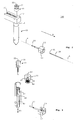
- the needle 20 has two outer diameters D1 and D2 (see also Fig. 7 ) and is provided at a first end 14 with the larger outer diameter D2 with a blind bore 16 having an inner diameter Di which is slightly larger than the outer diameter of the cable 30 to be equipped.
- This first end 14 of the needle 12 is at the beginning of the process held by closed centering jaws 13 of a centering gripper, which, as in Fig. 1A shown, stand in position x3.
- the centering gripper is only in Fig. 9 indicated schematically.
- the second end 15 of the needle 12 is in position x4 and has a smaller outer diameter D1, which corresponds approximately to the inner diameter of a through hole 21 of the unpopulated spout 20 (see Fig. 8 ).
- the Aufschiebeddling P1 sets in the example shown a linear distance, whose length is defined by the difference x2 - x1.
- Fig. 1B the state after pushing the spout 20 on the needle 12 is shown.
- the spout 20 including slide 11 is now located on the area of the needle 12, which has a larger outer diameter than the end 15 of the needle 12.
- the sprung jaws of the slide 11 allow an automatic adjustment of the distance of the jaws 44 (see Fig. 3 ) to the changing outer diameter of the needle 12.
- the centering jaws 13 of the mounting device or the mounting device 100 are made stationary in this example and remain at the position x3. Here you can only perform an opening and closing movement perpendicular to the x-axis. You may be able to do it manually be moved and fixed to make adjustments depending on the size and shape of the spout 20 can.
- the centering jaws 13 are designed to be movable so that they can perform a feed movement in the direction of the cable 30 parallel to the x-axis. In this case, no drive is required (drive A4 in Fig. 9 ) for moving the cable 30.
- a blind hole 16 can also be another recording (eg, a through hole, or a mounting lug) are used for receiving a cable end.
- the left end of the cable 30 travels a distance from the position x5 to the position x6.
- the centering jaws 13 form a central opening 17, as in the FIGS. 1A to 1G can be seen.
- the state after the insertion of the cable 30 into the blind hole 16 of the needle 12 is in Fig. 1C shown.
- the direction of movement of the cable 12 is represented by the arrow P2.
- the cable 30 can also be pushed into the needle 12, for example, before the grommet 20 has been pushed from the left.
- the cable 30 may also remain in the position x5 while the centering jaws 13 together with the needle 12 are moved towards the cable 30.
- the actual assembly ie the transfer of the spout 20 to the cable 30 is carried out by a backward movement P4 of the clamping element 10, as in Fig. 1D shown.
- the clamping element 10 together with the needle 12 performs a movement from x8 to x9.
- the needle 12 is pulled out between the spout 20 and the cable 30.
- the spout 20 is held by the fixed slide 11 in its position x2.
- the backward movement P4 is performed by the clamping member 10 which holds the needle 12 and moves it to the left.
- the needle 12 is moved back by the clamping member 10 by a movement P6 back to the starting position.
- the clamping element 10 carries out here together with the needle 12 a movement from the position x9 to the position x8.
- the left end of the needle 12 again reaches the position x4.
- Fig. 1F a state is shown in which the needle 12 has reached the starting position x4.
- the clamping member 10 can release the needle 12 and the next spout 20 can be pushed onto the needle 12, as described above.
- the clamping element 10 is e.g. transferred back to position x7.
- the pusher 11 and the clamping element 10 are preferably integrated in a mounting head 40, which is part of a mounting device or a mounting device 100.
- the placement head 40 is designed to pivot into the cable axis A and to provide the necessary longitudinal movements P1, P4, P6 in the direction of the cable axis A can make.
- the cable axis A runs parallel to the x-axis of the FIGS. 1A to 1G , The corresponding pivot drive for performing the pivotal movement in the cable axis A is not shown.
- the loading principle of the invention can also be used in alternative Tüllenzu operationen, so for example a horizontal feed of the spouts 20 is possible.
- a corresponding mounting device 100 is shown, in which no pivoting movement of the Tüllenzu Entry is provided.
- a singulation tool 41 which comprises an inner mandrel 50 and a sleeve 51 shown.
- the dicing tool 41 has the task of bringing the spouts 20 out of the conveyor rail 42 into the placement head 40.
- the inner mandrel 50 is first pushed through the hole of the spout 20 and then pressed the spout 20 by lowering the sleeve 51 from the conveyor rail 42 into the mounting head 40.
- This process is in Fig. 4 to recognize where a provided with the reference numeral 20.1 spout is just pushed out of the conveyor rail 42 down in the direction P8.
- the necessary for the movements of the mounting head 40 and the cable 30 drives A1 - A5 are in Fig. 9 shown purely schematically.
- the pivoting movement in the direction of the cable axis A can be motorized or with a pneumatic swivel drive.
- the various longitudinal movements can be carried out pneumatically or by means of a programmable longitudinal axis.
- the slide 11 is preferably constructed as a replaceable unit and designed so that it the spout 20 in the receiving bore 43, see Fig. 3 , can hold.
- the spout 20 can not fall out during the pivotal movement of the mounting head 40, the receiving bore 43 is formed accordingly. It would also be possible to hold the spout 20 in the receiving bore 43 by applying a vacuum.
- the two symmetrically arranged Aufschiebebacken 44 of the slide 11 are pressed with a compression spring 46 in the arranged behind the receiving bore 43 cone 45 of the slide 11.
- When pushing on the Aufschiebebacken 44, guided by the cone 45, can move radially apart and thus follow the contour (ie, the increasing outer circumference) of the needle 12. This is necessary because the needle 12 has a circumference that changes in the x-direction as described.
- the clamping element 10 is designed as a collet 47.
- Such collets 47 are used for example in a similar form on lathes.
- the collet 47 is attached to a pull rod 49 and can be pulled with this in a sleeve 48, which causes the closing of the collet 47 and thus the clamping of the needle 12.
- the pull rod 49 has to close or open the collet 47 perform only a short stroke, which can be advantageously realized with a pneumatic cylinder, not shown, which performs movements in the direction P9.
- the collet 47 must be in the open and closed state within the placement head 40 can be moved. This relative movement is advantageously carried out pneumatically.
- a commercially available pneumatic centering gripper 60 see, eg Fig. 9 ) are used.
- the centering jaws 13 are to be designed so that the needle 12 is securely clamped in the closed state and that access through an opening 17 through to the blind hole 16 is possible.
- the bore diameter of the opening 17 of the centering jaws 13 of the centering gripper 60 is slightly smaller than the diameter Di of the blind hole (blind bore) 16 in the needle 12 form.
- Fig. 7 shows a schematic sectional view of a needle 12, which can be used according to the invention.
- the needle 12 shown has a blind hole 16 which is coaxial with the needle longitudinal axis B.
- the needle 12 is made in one piece in all embodiments.
- the outer diameter of the needle 12 is smaller at a first end 15 than at a second end 14.
- the first outer diameter D1 is constant in the region 15 and the second outer diameter D2 is constant in the region 14.
- the blind hole 16 preferably extends from the right end of the needle 12 in the direction of the second end 15th
- the blind hole 16 ends in all embodiments before the transition region 18.
- the diameter D1, D2, the length of the needle 12 and the depth of the blind hole 16 depend on the design and size of the spout 20 and from the position at which the spout 20 should sit on the cable 30.
- the inner diameter Di of the blind hole 16 is slightly larger than the outer diameter of the cable 30 including insulation.
- a piece of cable 30 to be assembled is shown to the right of the needle 12 to illustrate the dimensions in this schematic.
- Fig. 8 shows a schematic sectional view of the end piece 15 of a one-piece needle 12, which can be used according to the invention.
- an exemplary grommet 20 having a central through-opening 21 is shown.
- the cable 30 passes through this passage opening 21 therethrough. Due to the elasticity of the grommet 20 this sits firmly on the cable 30th
- Fig. 5 shows in a sectional view of further details of the embodiment which has already been described. Shown is a moment before the transfer of the spout 20 to the cable 30. The illustration in Fig. 5 is roughly equivalent to in Fig. 1C shown situation. The transfer takes place by the backward movement (arrow P4) of the clamping element together with needle 12, as described.
- the invention also allows a reduced movement sequence to reduce the required free cable projection K, as in Fig. 6 indicated.
- Fig. 6 indicated.
- the needle 12 is slightly withdrawn after opening the centering jaws 13 and then the placement head 40 moves between the open centering jaws 13 to the cable 30 in the x direction.
- the clamping element 10 must approach in this case three different positions.
- a small cable protrusion K is particularly advantageous in so-called "jacketed cables".
- cables wrapped with a coat. This coat must be removed before processing.
- the so-called shroud length should often be kept as small as possible and depends on the required cable projection K.
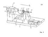
- FIG. 9 an exemplary placement apparatus 100 is shown having a common machine bed 61.
- the centering gripper 60 comprises the two centering jaws 13 and is seated on a first carriage 62, which can be moved linearly along the x-axis here.
- the first carriage 62 may comprise a corresponding first linear, spindle or pneumatic drive A1.
- This drive A1 is integrated in the carriage 62 or attached to this carriage 62.
- the centering jaws 13 hold in the moment shown the needle 12.
- the cable 30 has already been inserted through the opening 17 of the centering jaws 13 in the blind hole 16 of the needle 12.
- a second carriage 63 may be provided, which can be moved linearly along the x-axis here.
- the second carriage 63 may comprise a corresponding second linear, spindle or pneumatic drive A2.
- This drive A2 is integrated in the carriage 63 or attached to this carriage 63.
- the cable 30 can be held by two jaws 64, 65, for example. One of these jaws 64 (here the rear) can be movable, while the other jaw 65 (here the front) is fixed.
- the placement head 40 is not pivotable here, ie it is always aligned in the x direction, but can perform the feed movements and Rügzugsschien parallel to the x-axis, as described above.
- the internal structure of the mounting head 40 can according to the FIGS. 5 or 6 be executed.
- a third carriage 66 may be provided, which can be moved linearly along the x-axis here.
- the third carriage 66 may comprise a corresponding third linear, spindle or pneumatic drive A3.
- This drive A3 is integrated in the carriage 66 or attached to this carriage 66.
- the various gripper movements and / or other movements are preferably carried out pneumatically.
- insertion device 100 can perform a movement of the centering gripper 60 in the cable direction. This is in principle not necessary for carrying out the assembly process according to the invention, but can be used, for example, for taking over the spout 20 (not shown). This movement of the centering gripper 60 in the cable direction is thus optional.
- all movements may be relative movements.
- these relative movements result from a combination of motions generated by the various drives A1-A5 (e.g., seated in or on the carriages 62, 63, 66). But it may also be single movements caused by only one drive.
- the spouts 20 or the other elastic cable elements must be spread less than the state of Technology.
- the treatment and handling of the spouts 20 and other elastic cable elements is gentler.
- the risk of damage is reduced.
Landscapes
- Engineering & Computer Science (AREA)
- Manufacturing & Machinery (AREA)
- Automatic Assembly (AREA)
Claims (12)
- Dispositif de raccordement (100) pour raccorder un câble (30) à un élément élastique pour câble (20), le dispositif de raccordement (100) comprenant un corps pour enfiler l'élément élastique pour câble (20) et des moyens pour transférer l'élément élastique pour câble (20) depuis le corps d'enfilage sur le câble (30), une aiguille (12), qui sert de corps d'enfilage, présentant un diamètre extérieur (D1, D2), qui est plus petit à une première extrémité (15) qu'à une deuxième extrémité (14), et le dispositif de raccordement (100) comprenant des mâchoires de centrage (13) pour fixer l'aiguille (12) dans la région de la deuxième extrémité (14), les mâchoires de centrage (13) formant une ouverture (17) dans l'état fermé, caractérisé en ce que l'aiguille (12), dans la région de la deuxième extrémité (14), est pourvue d'un logement (16) pour recevoir coaxialement une extrémité du câble (30), et l'ouverture (17) des mâchoires de centrage (13) sert d'accès au logement (16) de l'aiguille (12), et en ce que le dispositif de raccordement (100) comprend un poussoir (11) pour enfiler l'élément élastique pour câble (20) sur l'aiguille (12) depuis la première extrémité (15) de l'aiguille (12) dans la direction de la deuxième extrémité (14) et un élément de serrage (10) pour retenir l'aiguille (12) dans la région de la première extrémité (15).
- Dispositif de raccordement (100) selon la revendication 1, comprenant en outre :- un entraînement (A3) pour effectuer un mouvement relatif (P1) du poussoir (11) par rapport aux mâchoires de centrage (13),- un entraînement (A4, A5) pour effectuer un mouvement relatif de l'élément de serrage (10) par rapport aux mâchoires de centrage (13),- un entraînement (A2) pour effectuer un mouvement relatif (P2) du câble (30) par rapport aux mâchoires de centrage (13), et- un entraînement (A1) pour ouvrir et fermer les mâchoires de centrage (13).
- Dispositif de raccordement (100) selon la revendication 1 ou 2, dans lequel le poussoir (11) est pourvu de mâchoires d'enfilage (44) à ressort, afin de pouvoir s'adapter, dans le cas d'un mouvement d'enfilage (P1) le long de l'axe longitudinal (B) de l'aiguille, à un diamètre extérieur variable de l'aiguille (12).
- Dispositif de raccordement (100) selon la revendication 1, 2 ou 3, dans lequel le poussoir (11) peut être fixé dans une position pendant que l'aiguille (12) effectue un mouvement de retour (P4) par le biais de l'entraînement correspondant.
- Dispositif de raccordement (100) selon l'une quelconque des revendications précédentes, dans lequel l'élément de serrage (10) est réalisé sous forme de pince de serrage (47) qui comprend une tige de traction (49) et qui repose dans une douille (48), la pince de serrage (47) pouvant être ouverte ou fermée par un mouvement de coulissement (P9).
- Dispositif de raccordement (100) selon l'une quelconque des revendications précédentes, dans lequel le poussoir (11) et l'élément de serrage (10) sont intégrés dans une tête de raccordement (40).
- Dispositif de raccordement (100) selon l'une quelconque des revendications précédentes, dans lequel l'élément élastique pour câble (20) est un passe-câble (20).
- Procédé pour raccorder un câble (30) à un élément élastique pour câble (20), comprenant les étapes suivantes :- fixation d'une aiguille (12) par des mâchoires centrales (13), l'aiguille (12) ayant un diamètre extérieur (D1, D2), qui est plus petit à une première extrémité (15) qu'à une deuxième extrémité (14), et l'aiguille (12) présentant dans la région de la deuxième extrémité (14) un logement (16) pour recevoir coaxialement une extrémité du câble (30),- enfilage de l'élément élastique pour câble (20) sur l'aiguille (12) depuis la première extrémité (15) de l'aiguille (12) dans la direction de la deuxième extrémité (14), un poussoir (11) étant utilisé pour l'enfilage,- réalisation d'un métallique relatif pour introduire le câble (30) à travers une ouverture (17) des mâchoires centrales (13) dans le logement (16) de l'aiguille (12),- fixation de l'aiguille (12) avec un élément de serrage (10) dans la région de la première extrémité (15),- ouverture des mâchoires de centrage (13),- transfert de l'élément élastique pour câble (20) depuis l'aiguille (12) sur le câble (30) par la réalisation d'un mouvement de retour relatif (P4) de l'aiguille (12), l'élément élastique pour câble (20) étant maintenu en position par le poussoir (11) pendant le mouvement de retour (P4) et étant enfilé sur le câble (30), et- réalisation d'un mouvement relatif pour retirer le câble (12) conjointement avec l'élément élastique pour câble (20).
- Procédé selon la revendication 8, dans lequel le poussoir (11) est pourvu de mâchoires d'enfilage (44) à ressort et lors de l'enfilage de l'élément élastique pour câble (20), s'adapte automatiquement à un diamètre variable de l'aiguille (12).
- Procédé selon la revendication 8 ou 9, dans lequel le poussoir (11) peut être fixé dans une position pendant que l'aiguille (12) effectue le mouvement de retour (P4) par le biais de l'entraînement correspondant.
- Procédé selon l'une quelconque des revendications 8 à 10, dans lequel l'élément de serrage (10) est réalisé sous forme de pince de serrage (47) qui comprend une tige de traction (49) et qui repose dans une douille (48), la pince de serrage (47) pouvant être ouverte ou fermée par un mouvement de coulissement (P9).
- Procédé selon l'une quelconque des revendications 8 à 11, dans lequel l'élément élastique pour câble (20) est un passe-câble (20).
Priority Applications (1)
| Application Number | Priority Date | Filing Date | Title |
|---|---|---|---|
| EP11157888A EP2372848B1 (fr) | 2010-03-30 | 2011-03-11 | Dispositif et procédé de mise en place de câbles avec des manchons |
Applications Claiming Priority (2)
| Application Number | Priority Date | Filing Date | Title |
|---|---|---|---|
| EP10158413 | 2010-03-30 | ||
| EP11157888A EP2372848B1 (fr) | 2010-03-30 | 2011-03-11 | Dispositif et procédé de mise en place de câbles avec des manchons |
Publications (2)
| Publication Number | Publication Date |
|---|---|
| EP2372848A1 EP2372848A1 (fr) | 2011-10-05 |
| EP2372848B1 true EP2372848B1 (fr) | 2012-11-14 |
Family
ID=42357656
Family Applications (1)
| Application Number | Title | Priority Date | Filing Date |
|---|---|---|---|
| EP11157888A Active EP2372848B1 (fr) | 2010-03-30 | 2011-03-11 | Dispositif et procédé de mise en place de câbles avec des manchons |
Country Status (2)
| Country | Link |
|---|---|
| US (1) | US8967594B2 (fr) |
| EP (1) | EP2372848B1 (fr) |
Families Citing this family (5)
| Publication number | Priority date | Publication date | Assignee | Title |
|---|---|---|---|---|
| PL2793327T3 (pl) | 2013-04-16 | 2018-06-29 | Schleuniger Holding Ag | Urządzenie do układania pojedynczych końcówek przewodów kabla |
| CN107346858B (zh) * | 2017-06-19 | 2019-05-28 | 昆山思柯马自动化设备有限公司 | 导线端部橡胶套的自动组装装置 |
| US10806579B2 (en) | 2017-10-20 | 2020-10-20 | Boston Scientific Scimed, Inc. | Heart valve repair implant for treating tricuspid regurgitation |
| JP7031380B2 (ja) | 2018-03-07 | 2022-03-08 | 日立金属株式会社 | ワイヤーシールの装着方法 |
| WO2022058993A1 (fr) * | 2020-09-21 | 2022-03-24 | Aptiv Technologies Limited | Systèmes et procédés de câblage automatisé |
Family Cites Families (15)
| Publication number | Priority date | Publication date | Assignee | Title |
|---|---|---|---|---|
| US1944890A (en) * | 1931-08-24 | 1934-01-30 | Hydraulic Brake Co | Hose coupling |
| US2657454A (en) * | 1947-12-24 | 1953-11-03 | Atlas Powder Co | Strand insertion |
| GB1444245A (en) * | 1973-09-18 | 1976-07-28 | Bicc Ltd | Apparatus for applying grommets to electric cables |
| US4063351A (en) * | 1976-12-20 | 1977-12-20 | International Telephone And Telegraph Corporation | Electrical connector assembly apparatus and method of connector fabrication |
| US4653182A (en) * | 1984-04-17 | 1987-03-31 | Sumitomo Electric Industries, Ltd. | Apparatus for fitting terminals and rubber stoppers on wires |
| JPH0275182A (ja) * | 1988-09-12 | 1990-03-14 | Yazaki Corp | 防水栓を装着した線条体の製造方法及び製造装置 |
| GB8917145D0 (en) * | 1989-07-27 | 1989-09-13 | Amp Gmbh | Applying a bung seal to an electrical lead |
| US5083363A (en) * | 1990-07-25 | 1992-01-28 | Fatigue Technology, Inc. | Method of installing a grommet in a wall of composite material |
| US5142774A (en) * | 1991-05-30 | 1992-09-01 | Huck Manufacturing Co. | Apparatus and method for loading fastener collars onto a mandrel |
| JP2635480B2 (ja) * | 1992-04-23 | 1997-07-30 | 矢崎総業株式会社 | ゴム栓の電線への装着方法 |
| JP2635487B2 (ja) * | 1992-08-31 | 1997-07-30 | 矢崎総業株式会社 | ゴム栓の電線への装着方法 |
| CH689272A5 (de) * | 1993-05-06 | 1999-01-15 | Komax Holding Ag | Einrichtung zur Tuellenbestueckung von elektrischen Kabeln. |
| JPH09290332A (ja) * | 1996-03-01 | 1997-11-11 | Yazaki Corp | ゴム栓挿入装置とゴム栓供給方法及びゴム栓挿入方法 |
| EP1022821B1 (fr) | 1999-01-19 | 2004-01-07 | Pawo Systems AG | Méthode et dispositif pour appliquer des manchons |
| JP2008167592A (ja) | 2006-12-28 | 2008-07-17 | Tyco Electronics Amp Kk | シール部材装着装置 |
-
2011
- 2011-03-11 EP EP11157888A patent/EP2372848B1/fr active Active
- 2011-03-30 US US13/075,826 patent/US8967594B2/en active Active
Also Published As
| Publication number | Publication date |
|---|---|
| US8967594B2 (en) | 2015-03-03 |
| EP2372848A1 (fr) | 2011-10-05 |
| US20110239437A1 (en) | 2011-10-06 |
Similar Documents
| Publication | Publication Date | Title |
|---|---|---|
| DE102012020798B3 (de) | Vorrichtung und Verfahren zum Bearbeiten eines Endes eines Kabels | |
| EP1096628B1 (fr) | Méthode et dispositif pour dépouiller l'écran d'un câble | |
| EP2372848B1 (fr) | Dispositif et procédé de mise en place de câbles avec des manchons | |
| EP3270478A1 (fr) | Dispositif d'usinage d'extrémités de câble | |
| EP2320527B1 (fr) | Machine de montage de manchons | |
| EP2797182B1 (fr) | Dispositif de confection de câbles pour le raccourcissement, l'isolement et la confection d'un câble doté de contacts à sertir | |
| DE1114235B (de) | Verfahren und Anordnung zum Entfernen des Endes einer Umhuellung eines elektrischen Kabels | |
| DE3922437A1 (de) | Drahtbearbeitungsvorrichtung | |
| EP2272629A1 (fr) | Outil de presse et procédé de compression, notamment de pièces usinées tubulaires | |
| EP3449728A2 (fr) | Dispositif de remplissage d'enveloppes tubulaires | |
| WO2019134849A1 (fr) | Procédé et dispositif de fabrication de rotors et de stators, incluant la confection de fils de connexion | |
| DE202010001324U1 (de) | Vorrichtung zum Verdrillen von Leitungen | |
| DE102010017981A1 (de) | Einrichtung und Verfahren zum Zusammenführen von Leitern | |
| EP3804048B1 (fr) | Dispositif et procédé servant à usiner une extrémité d'un câble électrique | |
| EP2871732A1 (fr) | Dispositif d'ouverture du blindage tressé d'un câble | |
| DE19963885C1 (de) | Verfahren zum Aufweiten von flexiblen Rohren und Vorrichtung zur Durchführung des Verfahrens | |
| EP2409940B1 (fr) | Machine à traiter le câble électrique avec unité de compensation de longueur | |
| EP3651288A1 (fr) | Station de distribution | |
| DE3902697C2 (de) | Verfahren und Vorrichtung zum Abmanteln von isolierten Leitungen, insbesondere abgeschirmten Koaxialleitungen | |
| EP4148749A1 (fr) | Procédé et dispositif permettant d'appliquer automatiquement une bande adhésive d'une seule face à un câble ou à une extrémité de câble | |
| EP3487643A1 (fr) | Dispositif pour préparer à l'étirage une extrémité de tube | |
| DE10212993A1 (de) | Crimp-Verfahren | |
| EP2654141B1 (fr) | Procédé et dispositif de fabrication d'un connecteur | |
| DE2738863A1 (de) | Vorrichtung zum konischen aufweiten von tuben | |
| DE3608777C1 (en) | Method and device for monitoring the presence or absence of hose-type jacketing material on a tubular body |
Legal Events
| Date | Code | Title | Description |
|---|---|---|---|
| PUAI | Public reference made under article 153(3) epc to a published international application that has entered the european phase |
Free format text: ORIGINAL CODE: 0009012 |
|
| AK | Designated contracting states |
Kind code of ref document: A1 Designated state(s): AL AT BE BG CH CY CZ DE DK EE ES FI FR GB GR HR HU IE IS IT LI LT LU LV MC MK MT NL NO PL PT RO RS SE SI SK SM TR |
|
| AX | Request for extension of the european patent |
Extension state: BA ME |
|
| 17P | Request for examination filed |
Effective date: 20120224 |
|
| GRAP | Despatch of communication of intention to grant a patent |
Free format text: ORIGINAL CODE: EPIDOSNIGR1 |
|
| RIC1 | Information provided on ipc code assigned before grant |
Ipc: H01R 43/00 20060101AFI20120628BHEP Ipc: H01R 43/28 20060101ALI20120628BHEP |
|
| GRAS | Grant fee paid |
Free format text: ORIGINAL CODE: EPIDOSNIGR3 |
|
| GRAA | (expected) grant |
Free format text: ORIGINAL CODE: 0009210 |
|
| AK | Designated contracting states |
Kind code of ref document: B1 Designated state(s): AL AT BE BG CH CY CZ DE DK EE ES FI FR GB GR HR HU IE IS IT LI LT LU LV MC MK MT NL NO PL PT RO RS SE SI SK SM TR |
|
| REG | Reference to a national code |
Ref country code: GB Ref legal event code: FG4D Free format text: NOT ENGLISH |
|
| REG | Reference to a national code |
Ref country code: CH Ref legal event code: EP Ref country code: AT Ref legal event code: REF Ref document number: 584400 Country of ref document: AT Kind code of ref document: T Effective date: 20121115 |
|
| REG | Reference to a national code |
Ref country code: CH Ref legal event code: NV Representative=s name: INVENTIO AG, CH |
|
| REG | Reference to a national code |
Ref country code: IE Ref legal event code: FG4D Free format text: LANGUAGE OF EP DOCUMENT: GERMAN |
|
| REG | Reference to a national code |
Ref country code: DE Ref legal event code: R096 Ref document number: 502011000201 Country of ref document: DE Effective date: 20130110 |
|
| REG | Reference to a national code |
Ref country code: RO Ref legal event code: EPE |
|
| REG | Reference to a national code |
Ref country code: SK Ref legal event code: T3 Ref document number: E 13271 Country of ref document: SK |
|
| REG | Reference to a national code |
Ref country code: NL Ref legal event code: VDEP Effective date: 20121114 |
|
| REG | Reference to a national code |
Ref country code: LT Ref legal event code: MG4D |
|
| PG25 | Lapsed in a contracting state [announced via postgrant information from national office to epo] |
Ref country code: SE Free format text: LAPSE BECAUSE OF FAILURE TO SUBMIT A TRANSLATION OF THE DESCRIPTION OR TO PAY THE FEE WITHIN THE PRESCRIBED TIME-LIMIT Effective date: 20121114 Ref country code: HR Free format text: LAPSE BECAUSE OF FAILURE TO SUBMIT A TRANSLATION OF THE DESCRIPTION OR TO PAY THE FEE WITHIN THE PRESCRIBED TIME-LIMIT Effective date: 20121114 Ref country code: FI Free format text: LAPSE BECAUSE OF FAILURE TO SUBMIT A TRANSLATION OF THE DESCRIPTION OR TO PAY THE FEE WITHIN THE PRESCRIBED TIME-LIMIT Effective date: 20121114 Ref country code: LT Free format text: LAPSE BECAUSE OF FAILURE TO SUBMIT A TRANSLATION OF THE DESCRIPTION OR TO PAY THE FEE WITHIN THE PRESCRIBED TIME-LIMIT Effective date: 20121114 Ref country code: NO Free format text: LAPSE BECAUSE OF FAILURE TO SUBMIT A TRANSLATION OF THE DESCRIPTION OR TO PAY THE FEE WITHIN THE PRESCRIBED TIME-LIMIT Effective date: 20130214 Ref country code: ES Free format text: LAPSE BECAUSE OF FAILURE TO SUBMIT A TRANSLATION OF THE DESCRIPTION OR TO PAY THE FEE WITHIN THE PRESCRIBED TIME-LIMIT Effective date: 20130225 |
|
| PG25 | Lapsed in a contracting state [announced via postgrant information from national office to epo] |
Ref country code: SI Free format text: LAPSE BECAUSE OF FAILURE TO SUBMIT A TRANSLATION OF THE DESCRIPTION OR TO PAY THE FEE WITHIN THE PRESCRIBED TIME-LIMIT Effective date: 20121114 Ref country code: PL Free format text: LAPSE BECAUSE OF FAILURE TO SUBMIT A TRANSLATION OF THE DESCRIPTION OR TO PAY THE FEE WITHIN THE PRESCRIBED TIME-LIMIT Effective date: 20121114 Ref country code: LV Free format text: LAPSE BECAUSE OF FAILURE TO SUBMIT A TRANSLATION OF THE DESCRIPTION OR TO PAY THE FEE WITHIN THE PRESCRIBED TIME-LIMIT Effective date: 20121114 Ref country code: GR Free format text: LAPSE BECAUSE OF FAILURE TO SUBMIT A TRANSLATION OF THE DESCRIPTION OR TO PAY THE FEE WITHIN THE PRESCRIBED TIME-LIMIT Effective date: 20130215 Ref country code: PT Free format text: LAPSE BECAUSE OF FAILURE TO SUBMIT A TRANSLATION OF THE DESCRIPTION OR TO PAY THE FEE WITHIN THE PRESCRIBED TIME-LIMIT Effective date: 20130314 |
|
| PG25 | Lapsed in a contracting state [announced via postgrant information from national office to epo] |
Ref country code: RS Free format text: LAPSE BECAUSE OF FAILURE TO SUBMIT A TRANSLATION OF THE DESCRIPTION OR TO PAY THE FEE WITHIN THE PRESCRIBED TIME-LIMIT Effective date: 20121114 Ref country code: EE Free format text: LAPSE BECAUSE OF FAILURE TO SUBMIT A TRANSLATION OF THE DESCRIPTION OR TO PAY THE FEE WITHIN THE PRESCRIBED TIME-LIMIT Effective date: 20121114 Ref country code: DK Free format text: LAPSE BECAUSE OF FAILURE TO SUBMIT A TRANSLATION OF THE DESCRIPTION OR TO PAY THE FEE WITHIN THE PRESCRIBED TIME-LIMIT Effective date: 20121114 |
|
| PG25 | Lapsed in a contracting state [announced via postgrant information from national office to epo] |
Ref country code: NL Free format text: LAPSE BECAUSE OF FAILURE TO SUBMIT A TRANSLATION OF THE DESCRIPTION OR TO PAY THE FEE WITHIN THE PRESCRIBED TIME-LIMIT Effective date: 20121114 |
|
| PLBE | No opposition filed within time limit |
Free format text: ORIGINAL CODE: 0009261 |
|
| STAA | Information on the status of an ep patent application or granted ep patent |
Free format text: STATUS: NO OPPOSITION FILED WITHIN TIME LIMIT |
|
| BERE | Be: lapsed |
Owner name: KOMAX HOLDING A.G. Effective date: 20130331 |
|
| 26N | No opposition filed |
Effective date: 20130815 |
|
| PG25 | Lapsed in a contracting state [announced via postgrant information from national office to epo] |
Ref country code: MC Free format text: LAPSE BECAUSE OF NON-PAYMENT OF DUE FEES Effective date: 20130331 |
|
| PG25 | Lapsed in a contracting state [announced via postgrant information from national office to epo] |
Ref country code: CY Free format text: LAPSE BECAUSE OF FAILURE TO SUBMIT A TRANSLATION OF THE DESCRIPTION OR TO PAY THE FEE WITHIN THE PRESCRIBED TIME-LIMIT Effective date: 20121114 |
|
| REG | Reference to a national code |
Ref country code: DE Ref legal event code: R097 Ref document number: 502011000201 Country of ref document: DE Effective date: 20130815 |
|
| REG | Reference to a national code |
Ref country code: FR Ref legal event code: ST Effective date: 20131129 |
|
| REG | Reference to a national code |
Ref country code: IE Ref legal event code: MM4A |
|
| PG25 | Lapsed in a contracting state [announced via postgrant information from national office to epo] |
Ref country code: BE Free format text: LAPSE BECAUSE OF NON-PAYMENT OF DUE FEES Effective date: 20130331 Ref country code: FR Free format text: LAPSE BECAUSE OF NON-PAYMENT OF DUE FEES Effective date: 20130402 Ref country code: AL Free format text: LAPSE BECAUSE OF FAILURE TO SUBMIT A TRANSLATION OF THE DESCRIPTION OR TO PAY THE FEE WITHIN THE PRESCRIBED TIME-LIMIT Effective date: 20121114 Ref country code: IE Free format text: LAPSE BECAUSE OF NON-PAYMENT OF DUE FEES Effective date: 20130311 |
|
| PG25 | Lapsed in a contracting state [announced via postgrant information from national office to epo] |
Ref country code: MT Free format text: LAPSE BECAUSE OF FAILURE TO SUBMIT A TRANSLATION OF THE DESCRIPTION OR TO PAY THE FEE WITHIN THE PRESCRIBED TIME-LIMIT Effective date: 20121114 |
|
| PG25 | Lapsed in a contracting state [announced via postgrant information from national office to epo] |
Ref country code: SM Free format text: LAPSE BECAUSE OF FAILURE TO SUBMIT A TRANSLATION OF THE DESCRIPTION OR TO PAY THE FEE WITHIN THE PRESCRIBED TIME-LIMIT Effective date: 20121114 |
|
| PG25 | Lapsed in a contracting state [announced via postgrant information from national office to epo] |
Ref country code: TR Free format text: LAPSE BECAUSE OF FAILURE TO SUBMIT A TRANSLATION OF THE DESCRIPTION OR TO PAY THE FEE WITHIN THE PRESCRIBED TIME-LIMIT Effective date: 20121114 |
|
| PG25 | Lapsed in a contracting state [announced via postgrant information from national office to epo] |
Ref country code: HU Free format text: LAPSE BECAUSE OF FAILURE TO SUBMIT A TRANSLATION OF THE DESCRIPTION OR TO PAY THE FEE WITHIN THE PRESCRIBED TIME-LIMIT; INVALID AB INITIO Effective date: 20110311 Ref country code: LU Free format text: LAPSE BECAUSE OF NON-PAYMENT OF DUE FEES Effective date: 20130311 Ref country code: MK Free format text: LAPSE BECAUSE OF FAILURE TO SUBMIT A TRANSLATION OF THE DESCRIPTION OR TO PAY THE FEE WITHIN THE PRESCRIBED TIME-LIMIT Effective date: 20121114 |
|
| GBPC | Gb: european patent ceased through non-payment of renewal fee |
Effective date: 20150311 |
|
| PG25 | Lapsed in a contracting state [announced via postgrant information from national office to epo] |
Ref country code: GB Free format text: LAPSE BECAUSE OF NON-PAYMENT OF DUE FEES Effective date: 20150311 |
|
| PG25 | Lapsed in a contracting state [announced via postgrant information from national office to epo] |
Ref country code: IS Free format text: LAPSE BECAUSE OF FAILURE TO SUBMIT A TRANSLATION OF THE DESCRIPTION OR TO PAY THE FEE WITHIN THE PRESCRIBED TIME-LIMIT Effective date: 20121114 |
|
| REG | Reference to a national code |
Ref country code: AT Ref legal event code: MM01 Ref document number: 584400 Country of ref document: AT Kind code of ref document: T Effective date: 20160311 |
|
| PG25 | Lapsed in a contracting state [announced via postgrant information from national office to epo] |
Ref country code: AT Free format text: LAPSE BECAUSE OF NON-PAYMENT OF DUE FEES Effective date: 20160311 |
|
| REG | Reference to a national code |
Ref country code: DE Ref legal event code: R082 Ref document number: 502011000201 Country of ref document: DE Representative=s name: KILBURN & STRODE LLP, NL |
|
| PGFP | Annual fee paid to national office [announced via postgrant information from national office to epo] |
Ref country code: BG Payment date: 20230324 Year of fee payment: 13 |
|
| PGFP | Annual fee paid to national office [announced via postgrant information from national office to epo] |
Ref country code: IT Payment date: 20230321 Year of fee payment: 13 |
|
| PGFP | Annual fee paid to national office [announced via postgrant information from national office to epo] |
Ref country code: CH Payment date: 20230402 Year of fee payment: 13 |
|
| PGFP | Annual fee paid to national office [announced via postgrant information from national office to epo] |
Ref country code: RO Payment date: 20240229 Year of fee payment: 14 Ref country code: DE Payment date: 20240328 Year of fee payment: 14 Ref country code: CZ Payment date: 20240227 Year of fee payment: 14 Ref country code: SK Payment date: 20240227 Year of fee payment: 14 |