EP2372293A2 - Kühlvorrichtung - Google Patents
Kühlvorrichtung Download PDFInfo
- Publication number
- EP2372293A2 EP2372293A2 EP11159141A EP11159141A EP2372293A2 EP 2372293 A2 EP2372293 A2 EP 2372293A2 EP 11159141 A EP11159141 A EP 11159141A EP 11159141 A EP11159141 A EP 11159141A EP 2372293 A2 EP2372293 A2 EP 2372293A2
- Authority
- EP
- European Patent Office
- Prior art keywords
- filter
- cooling device
- connector
- refrigerant
- tube
- Prior art date
- Legal status (The legal status is an assumption and is not a legal conclusion. Google has not performed a legal analysis and makes no representation as to the accuracy of the status listed.)
- Withdrawn
Links
Images

Classifications
-
- F—MECHANICAL ENGINEERING; LIGHTING; HEATING; WEAPONS; BLASTING
- F28—HEAT EXCHANGE IN GENERAL
- F28F—DETAILS OF HEAT-EXCHANGE AND HEAT-TRANSFER APPARATUS, OF GENERAL APPLICATION
- F28F19/00—Preventing the formation of deposits or corrosion, e.g. by using filters or scrapers
- F28F19/01—Preventing the formation of deposits or corrosion, e.g. by using filters or scrapers by using means for separating solid materials from heat-exchange fluids, e.g. filters
-
- F—MECHANICAL ENGINEERING; LIGHTING; HEATING; WEAPONS; BLASTING
- F28—HEAT EXCHANGE IN GENERAL
- F28F—DETAILS OF HEAT-EXCHANGE AND HEAT-TRANSFER APPARATUS, OF GENERAL APPLICATION
- F28F3/00—Plate-like or laminated elements; Assemblies of plate-like or laminated elements
- F28F3/08—Elements constructed for building-up into stacks, e.g. capable of being taken apart for cleaning
-
- H—ELECTRICITY
- H05—ELECTRIC TECHNIQUES NOT OTHERWISE PROVIDED FOR
- H05K—PRINTED CIRCUITS; CASINGS OR CONSTRUCTIONAL DETAILS OF ELECTRIC APPARATUS; MANUFACTURE OF ASSEMBLAGES OF ELECTRICAL COMPONENTS
- H05K7/00—Constructional details common to different types of electric apparatus
- H05K7/20—Modifications to facilitate cooling, ventilating, or heating
-
- H—ELECTRICITY
- H10—SEMICONDUCTOR DEVICES; ELECTRIC SOLID-STATE DEVICES NOT OTHERWISE PROVIDED FOR
- H10W—GENERIC PACKAGES, INTERCONNECTIONS, CONNECTORS OR OTHER CONSTRUCTIONAL DETAILS OF DEVICES COVERED BY CLASS H10
- H10W40/00—Arrangements for thermal protection or thermal control
-
- H—ELECTRICITY
- H10—SEMICONDUCTOR DEVICES; ELECTRIC SOLID-STATE DEVICES NOT OTHERWISE PROVIDED FOR
- H10W—GENERIC PACKAGES, INTERCONNECTIONS, CONNECTORS OR OTHER CONSTRUCTIONAL DETAILS OF DEVICES COVERED BY CLASS H10
- H10W40/00—Arrangements for thermal protection or thermal control
- H10W40/40—Arrangements for thermal protection or thermal control involving heat exchange by flowing fluids
- H10W40/47—Arrangements for thermal protection or thermal control involving heat exchange by flowing fluids by flowing liquids, e.g. forced water cooling
Definitions
- the present invention relates generally to a cooling device for an electric device and more specifically to a cooling device having a filter.
- An electric device has a cooling device for cooling the electric device by allowing heat generated by a heat generator such as a semiconductor device mounted to the electric device to be radiated.
- the cooling device includes a cooler that has formed therein a passage by installation of fins in a sealed housing thereof.
- the cooler is operable to exchange heat generated by the heat generator with refrigerant such as water circulating through the passage, thereby cooling the heat generator.
- a cooler is connected to a radiator and a pump through a tube or a hose for circulating refrigerant. Since refrigerant used for the cooling device is contaminated by foreign particles produced from component parts of the refrigerant circuit and due to the deterioration of walls of such component parts, there is a fear that the passage in the cooler is clogged with the foreign particles. To solve this problem, the cooling device disclosed in Japanese Application Publication 2007-205694 uses a filter for refrigerant to prevent a passage in the cooler from being clogged with foreign particles.
- the cooling device disclosed in the above Publication is formed into an integral laminated structure in which an inlet side tube connection plate, a passage-enlarging plate, a filter plate, another passage-enlarging plate, an inlet side passage-restricting plate, a plurality of passage plates and heat transmission plates that are arranged alternately, an outlet side passage-restricting plate, another outlet side passage-enlarging plate and an outlet side tube connection plate are disposed in laminated arrangement in this order.
- Each heat transfer plate has formed at the center thereof a finned area and a micro passage is formed between any two adjacent finned areas of the heat transfer plates. Foreign particles contained in fluid flowing in from the inlet side tube connection plate are captured by the filter plate.
- the cooling device can prevent the micro passage formed between any two adjacent finned areas from being clogged with the foreign particles, thus preventing an increase of load of the pump and deterioration of the cooling performance and achieving effective cooling of the heat generator.
- the laminated structure is formed by bonding the components together by any suitable means. Furthermore, heat generators are joined to a plurality of heat transmission plates in the laminate structure by brazing or soldering, so that it is practically impossible to disassemble the components in the laminated structure. Therefore, the filter sheet in the cooling device according to the above Publication cannot be cleaned, so that it is not suitable for use for a long time.
- the present invention is directed to providing a cooling device which facilitates the removal of foreign particles attached to a filter.
- a cooling device includes a refrigerant inlet, a refrigerant outlet, a cooler including therein a refrigerant passage, an introduction tube communicating with the refrigerant inlet and a filter detachably disposed between the refrigerant inlet and the introduction tube.
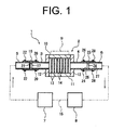
- FIG. 1 taken as a front view.
- the cooling device of the first embodiment is designated by 1.
- the cooling device 1 includes a cooler 2, an inlet tube 3, an outlet tube 4, an introduction tube 5, a delivery tube 6, a first connector 16, a second connector 23, a filter 21, a pump 7 and a radiator 8.
- An electric device formed by a heat generator 9 such as a semiconductor module including thermally-conducting material is joined to top surface of the cooler 2 by soldering.
- the cooler 2 includes a top plate 10, a bottom plate 11 spaced from the top plate 10 at a predetermined distance, side plates 12 connecting outer peripheries of the top plate 10 and the bottom plate 11, a plurality of arrays of fins 13, the inlet tube 3 and the outlet tube 4 connected to the respective side plates.
- the top plate 10, the bottom plate 11 and the side plates 12 cooperate to form a housing as a part of the cooler 2 through which refrigerant flows.
- the arrays of fins 13 are provided extending between the top plate 10 and the bottom plate 11 and a refrigerant passage 14 is formed between any two adjacent arrays of fins 13 in the cooler 2.
- the top plate 10, the bottom plate 11, the side plates 12, the fins 13, the inlet tube 3 and the outlet tube 4 that form the cooler 2 are made of a metal containing mainly aluminum with high heat transference.
- the inlet tube 3 is fixedly inserted through one side plate 12 of the cooler 2 for communicating with the refrigerant passage 14, forming a refrigerant inlet of the cooler 2.
- the outlet tube 4 is fixedly inserted through the other side plate 12 for communicating with the refrigerant passage 14, forming a refrigerant outlet of the cooler 2.
- the introduction tube 5 is connected to the pump 7 and the delivery tube 6 is connected to a radiator 8.
- the pump 7 and the radiator 8 are connected to each other through a tube 15.
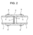
- the first connector 16 is made of an annular tube having formed therein two large-diameter passages 18, 19 and an annular projection 17 projecting inward between the large-diameter passages 18, 19 and forming a small-diameter passage. That is, the large-diameter passages 18, 19 and the small-diameter passage are formed in the first connector 16 and refrigerant flows from the large-diameter passage 19 toward the large-diameter passage 18 through the center small-diameter passage.
- the inner diameters of the large-diameter passages 18, 19 are substantially the same as the outer diameters of the inlet tube 3 and the introduction tube 5, respectively.
- the outer diameters of the inlet tube 3 and the introduction tube 5 may be substantially the same.
- the inner diameter of the small-diameter passage formed by the projection 17 is substantially the same as the inner diameter of the inlet tube 3 and the introduction tube 5.
- the first connector 16 corresponds to a connector:
- the inlet tube 3 is inserted in the large-diameter passage 18 of the first connector 16 on the downstream side thereof with respect to the refrigerant flowing direction.
- the inlet tube 3 is detachably fixed to the first connector 16 by a plurality of bolts 20 with the end surface of the inlet tube 3 in contact with downstream side surface of the projection 17.
- the introduction tube 5 is detachably fixed to the first connector 16 by a plurality of bolts 22 with the end surface of the introduction tube 5 in contact with a filter 21.
- the filter 21 is formed in a cylindrical shape having an outer diameter that is substantially the same as the inner diameter of the large-diameter passage 19.
- the filter 21 is detachably inserted in the large-diameter passage 19 so that radially outer part of the end surface of the filter 21 on the downstream side thereof is in contact with upstream side surface of the projection 17.
- the filter 21 is made of a metal such as stainless steel, glass fiber, or a resin such as polyurethane and nylon.
- the filter 21 which is always exposed to refrigerant should preferably be made of any corrosion-resistant material.
- the mesh opening size of the filter 21 is smaller than the width of the refrigerant passage 14 defined by the arrays of fins 13 in the cooler 2, so that foreign particles in refrigerant can be captured by the filter 21 and the filter 21 prevents the refrigerant passage 14 from being clogged.
- the second connector 23 has substantially the same structure as the first connector 16 and an annular projection 24 is formed at the center thereof.
- the second connector 23 connects the outlet tube 4 and the delivery tube 6 together.
- the outlet tube 4 is inserted in the large-diameter passage 25 of the second connector 23 on the upstream side thereof with respect to the refrigerant flowing direction.
- the outlet tube 4 is fixed to the second connector 23 by a plurality of bolts 26 with the end surface of the outlet tube 4 in contact with the upstream side surface of the projection 24.
- the delivery tube 6 is inserted in the large-diameter passage 27 of the second connector 23 on the downstream side thereof.
- the delivery tube 6 is fixed to the second connector 23 by a plurality of bolts 28 with the end surface of the delivery tube 6 in contact with downstream side surface of the projection 24. If the introduction tube 5 and the delivery tube 6 are made of a flexible material, assembling the introduction tube 5 and the delivery tube 6 to the first and the second connectors 16, 23, respectively can be facilitated.
- refrigerant supplied from the pump 7 into the introduction tube 5 is filtered through the filter 21 and flows through the inlet tube 3 into the cooler 2.
- refrigerant is exchanged heat with the heat generator 9 in the cooler 2 while passing through the refrigerant passage 14 and flows out to the outlet tube 4.
- Refrigerant discharged from the cooler 2 flows through the delivery tube 6 to the radiator 8 for being cooled.
- Refrigerant cooled in the radiator 8 flows through the tube 15 to the pump 7 which feeds refrigerant to the introduction tube 5 again.
- the cooler 2 cools the heat generator 9 by circulating refrigerant.
- the filter 21 becomes clogged with foreign particles, so that the flow rate of refrigerator passing through the filter 21 decreases.
- the operation of the cooling device 1 is stopped and the introduction tube 5 and the inlet tube 3 are removed from the first connector 16 by loosening the bolts 20, 22.
- the filter 21 can be removed from the first connector 16 easily.
- the filter 21 removed from the first connector 16 can be cleaned with water, so that foreign particles that are attached to the filter 21 can be removed easily. If the filter 21 is not removed from the first connector 16 only by inclining the first connector 16, a rod-like member may be inserted into the first connector 16 from the downstream end thereof to remove the filter 21.
- the cooling device 1 can be restored by installing the cleaned filter 21 in place in the large-diameter passage 19 of the first connector 16 and subsequently connecting the inlet tube 3 and the introduction tube 5 to the first connector 16, as shown in FIGS. 1 and 2 . Since the filter 21 can be cleaned periodically and easily, the cooler 2 can maintain smooth flow of refrigerant in the refrigerant passage 14 and permits efficient radiation of heat generated by the heat generator 9.
- the cooling device according to the second embodiment differs from that of the first embodiment in the manner of installation of the filter.
- the following description will use the same reference numerals for the common elements or components in the first and the second embodiments and the description of such common elements or components will be omitted.
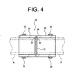
- the connector 29 connecting the inlet tube 3 and the introduction tube 5 is formed by a pair of annular tubes 30, 31 that are joined together in an end-to-end manner and have an inner diameter that is substantially the same as the outer diameter of the inlet tube 3 or the introduction tube 5.
- Annular grooves 32, 33 are formed in the joined end surfaces of the tubes 30, 31 on the radially inner side, respectively.
- the tubes 30, 31 are joined together by brazing filler metal 34 with the filter 21 fitted at the outer periphery thereof in the annular grooves 32, 33.
- the tubes 30, 31 may be detachably joined together mechanically by any other suitable fastening means such as bolts.
- the tubes 30, 31 and the filter 21 are integrally formed into the connector 29.
- the inlet tube 3 is inserted into the tube 30 and fixed by bolts 20 with the end surface of the inlet tube 3 in contact with the end surface of the filter 21 on the downstream side thereof with respect to the refrigerant flowing direction.
- the introduction tube 5 is inserted into the tube 31 and fixed by bolts 22 with end surface of the introduction tube 5 in contact with the other end surface of the filter 21 on the upstream side thereof.
- the filter 21 is thus interposed between the inlet tube 3 and the introduction tube 5 and refrigerant is filtered in stable condition.
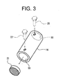
- the filter 21 is cleaned as follows.
- the inlet tube 3 and the introduction tube 5 are removed from the connector 29 by loosening the bolts 20, 22.
- the foreign particles attached to the end surface of the filter 21 on its upstream side can be removed by directing a hose 37 that is connected to a washing device (not shown) toward the inside of the tube 31 and injecting cleaning liquid 38 such as water.
- the foreign particles deposited in the filter 21 can be removed easily by directing the hose 37 toward the inside of the tube 30 and injecting cleaning liquid 38.
- the filter 21 can be cleaned entirely and easily.
- the present invention is not limited to the above embodiments.
- the present invention may be practiced in various ways within the scope of the present invention, as exemplified below.
- a cooling device includes a refrigerant inlet, a refrigerant outlet, a cooler including therein a refrigerant passage, an introduction tube communicating with the refrigerant inlet and a filter detachably disposed between the refrigerant inlet and the introduction tube.
Landscapes
- Engineering & Computer Science (AREA)
- Physics & Mathematics (AREA)
- Thermal Sciences (AREA)
- Mechanical Engineering (AREA)
- General Engineering & Computer Science (AREA)
- Microelectronics & Electronic Packaging (AREA)
- Cooling Or The Like Of Semiconductors Or Solid State Devices (AREA)
- Cooling Or The Like Of Electrical Apparatus (AREA)
- Devices That Are Associated With Refrigeration Equipment (AREA)
Applications Claiming Priority (1)
| Application Number | Priority Date | Filing Date | Title |
|---|---|---|---|
| JP2010075487A JP5348047B2 (ja) | 2010-03-29 | 2010-03-29 | 冷却装置 |
Publications (2)
| Publication Number | Publication Date |
|---|---|
| EP2372293A2 true EP2372293A2 (de) | 2011-10-05 |
| EP2372293A3 EP2372293A3 (de) | 2014-01-29 |
Family
ID=44260076
Family Applications (1)
| Application Number | Title | Priority Date | Filing Date |
|---|---|---|---|
| EP11159141.8A Withdrawn EP2372293A3 (de) | 2010-03-29 | 2011-03-22 | Kühlvorrichtung |
Country Status (5)
| Country | Link |
|---|---|
| US (1) | US8584483B2 (de) |
| EP (1) | EP2372293A3 (de) |
| JP (1) | JP5348047B2 (de) |
| KR (1) | KR101249621B1 (de) |
| CN (1) | CN102209459B (de) |
Families Citing this family (7)
| Publication number | Priority date | Publication date | Assignee | Title |
|---|---|---|---|---|
| JP5780475B2 (ja) * | 2014-08-19 | 2015-09-16 | 株式会社タツノ | 異物混入検知装置 |
| CN104334005B (zh) * | 2014-11-28 | 2017-01-25 | 成都泰格微波技术股份有限公司 | 一种全密封式散热腔体 |
| CN104470305A (zh) * | 2014-12-04 | 2015-03-25 | 电子科技大学 | 一种用于人体外骨骼机器人的电路板位置调节装置 |
| JP6141538B2 (ja) | 2015-04-20 | 2017-06-07 | 三菱電機株式会社 | 異物除去装置、循環システム及び車両用冷却システム |
| CN105547351A (zh) * | 2015-12-10 | 2016-05-04 | 无锡拓能自动化科技有限公司 | 一种方便调整角度的防烧损火焰探测器 |
| JP7545720B2 (ja) * | 2020-10-23 | 2024-09-05 | 株式会社イー・エム・ディー | 冷却装置 |
| CN112556482A (zh) * | 2020-12-10 | 2021-03-26 | 黄友平 | 一种避免堵塞方便清理维护的水式热交换器 |
Citations (2)
| Publication number | Priority date | Publication date | Assignee | Title |
|---|---|---|---|---|
| JP2007205694A (ja) | 2006-02-06 | 2007-08-16 | Seiko Epson Corp | 流体冷却装置、および電子機器 |
| JP2007266370A (ja) * | 2006-03-29 | 2007-10-11 | Toyota Motor Corp | 半導体装置の製造方法および製造装置 |
Family Cites Families (20)
| Publication number | Priority date | Publication date | Assignee | Title |
|---|---|---|---|---|
| FR1547279A (fr) * | 1967-12-18 | 1968-11-22 | Filtre pour moteur d'un véhicule automobile | |
| US3941697A (en) * | 1974-12-30 | 1976-03-02 | Johnson Louis B | Automotive cooling system filter assembly |
| US4364756A (en) * | 1981-07-07 | 1982-12-21 | Virginia Chemicals Inc. | Refrigerant suction line filter/filter-drier and method for the construction thereof |
| US5281331A (en) * | 1992-10-28 | 1994-01-25 | Golan Ilan Z | Radiator fluid filter |
| US5340881A (en) | 1992-11-16 | 1994-08-23 | The University Of Akron | Aldehyde-telechelic polyisobutylenes, catalytic method for preparing the same with high conversion and selectivity, and block copolymers made thereform |
| US5707518A (en) * | 1996-01-17 | 1998-01-13 | White Consolidated Industries, Inc. | Refrigerator water filter |
| JP3203475B2 (ja) * | 1996-06-28 | 2001-08-27 | 株式会社日立製作所 | 半導体装置 |
| JP2001127657A (ja) * | 1999-10-28 | 2001-05-11 | Nec Corp | 放送情報の提供方法及び放送情報提供装置 |
| US6669451B1 (en) * | 2000-07-06 | 2003-12-30 | Thomas M. Wall | Screen plate filter for low pressure side of automotive air conditioning compressor |
| US6453697B1 (en) * | 2001-04-23 | 2002-09-24 | Designed Metal Products, Inc. | Seal for vessel and method of forming same |
| US6764593B1 (en) * | 2002-11-06 | 2004-07-20 | Scot M. Pace | Automobile air conditioning refrigerant filter |
| US6938437B2 (en) * | 2003-06-17 | 2005-09-06 | A-1 Components Corporation | Cylindrical seal for refrigerant tube connector |
| JP2005214785A (ja) * | 2004-01-29 | 2005-08-11 | Toyota Central Res & Dev Lab Inc | 抽出分離装置及び抽出分離部材 |
| KR100673380B1 (ko) * | 2004-12-20 | 2007-01-24 | 삼성전자주식회사 | 냉매로가 형성된 반도체 칩과, 그를 이용한 반도체 패키지및 반도체 패키지 냉각 시스템 |
| CH698487B1 (de) * | 2005-08-09 | 2009-08-31 | Resat Civelek | Rohrkupplungsanordnung. |
| JP2008153507A (ja) * | 2006-12-19 | 2008-07-03 | Toshiba Corp | フィルタユニット及びこれを具備する半導体パッケージ |
| US7992721B2 (en) * | 2007-09-20 | 2011-08-09 | Spx Corporation | Method and apparatus for confirming that a filter drier has been replaced |
| JP2009156526A (ja) * | 2007-12-27 | 2009-07-16 | Denso Corp | 冷凍サイクル装置のフィルタの収納構造 |
| JP5120284B2 (ja) | 2009-02-04 | 2013-01-16 | 株式会社豊田自動織機 | 半導体装置 |
| JP4881971B2 (ja) | 2009-03-26 | 2012-02-22 | 株式会社豊田自動織機 | 半導体装置 |
-
2010
- 2010-03-29 JP JP2010075487A patent/JP5348047B2/ja not_active Expired - Fee Related
-
2011
- 2011-03-22 EP EP11159141.8A patent/EP2372293A3/de not_active Withdrawn
- 2011-03-23 US US13/069,933 patent/US8584483B2/en not_active Expired - Fee Related
- 2011-03-25 CN CN201110080122.2A patent/CN102209459B/zh not_active Expired - Fee Related
- 2011-03-28 KR KR1020110027443A patent/KR101249621B1/ko not_active Expired - Fee Related
Patent Citations (2)
| Publication number | Priority date | Publication date | Assignee | Title |
|---|---|---|---|---|
| JP2007205694A (ja) | 2006-02-06 | 2007-08-16 | Seiko Epson Corp | 流体冷却装置、および電子機器 |
| JP2007266370A (ja) * | 2006-03-29 | 2007-10-11 | Toyota Motor Corp | 半導体装置の製造方法および製造装置 |
Also Published As
| Publication number | Publication date |
|---|---|
| US20110232316A1 (en) | 2011-09-29 |
| CN102209459B (zh) | 2015-04-22 |
| JP2011210846A (ja) | 2011-10-20 |
| EP2372293A3 (de) | 2014-01-29 |
| JP5348047B2 (ja) | 2013-11-20 |
| KR101249621B1 (ko) | 2013-04-01 |
| KR20110109932A (ko) | 2011-10-06 |
| US8584483B2 (en) | 2013-11-19 |
| CN102209459A (zh) | 2011-10-05 |
Similar Documents
| Publication | Publication Date | Title |
|---|---|---|
| US8584483B2 (en) | Semiconductor device | |
| US7658224B2 (en) | Flanged connection for heat exchanger | |
| KR102173362B1 (ko) | 전기소자 쿨링모듈 | |
| US20170365890A1 (en) | Heat exchanger for cooling electrical element | |
| KR20130133196A (ko) | 열교환기, 열 교환기 조립체 및 그 정비 방법 | |
| CN1409589A (zh) | 用于大功率电子设备机柜的模块化冷却系统和热总线 | |
| EP3009755B1 (de) | Ausseneinheit für klimaanlage und herstellungsverfahren für ausseneinheit für klimaanlage | |
| US9807915B2 (en) | Heat exchanger for cooling electric element | |
| CN105814685B (zh) | 半导体模块用冷却器及其制造方法 | |
| JP2017045971A (ja) | 冷却器モジュール、および冷却器モジュールの製造方法 | |
| CN108885064A (zh) | 用于机动车辆空调装置的热交换器的相变材料的储存器,其配备有用于填充所述储存器的填充管 | |
| KR102264504B1 (ko) | 전기소자 쿨링모듈 | |
| US5042572A (en) | Mounting assembly for modular heat exchanger units | |
| KR102161487B1 (ko) | 전기소자 냉각용 열교환기 | |
| EP1992803A2 (de) | Einbauanordnung für eine Ölkühler | |
| KR20160111661A (ko) | 전기소자 냉각용 열교환기 | |
| CN215260652U (zh) | 液冷系统 | |
| JP6459776B2 (ja) | 継手接続部のシール構造およびその製造方法 | |
| KR102089630B1 (ko) | 전기소자 냉각용 열교환기 제조방법 | |
| CN100541099C (zh) | 热交换装置的装配总成 | |
| CN220319918U (zh) | 一种鼓风机水冷装置 | |
| US20190055938A1 (en) | Adapter plate with heat exchanger for a pump and motor | |
| CN223035662U (zh) | 冷却器用密封端盖结构 | |
| CN219176926U (zh) | 一种应用于风电发电机行星式传动装置的冷却机构 | |
| KR102637655B1 (ko) | 압력에 의한 변형방지 기능을 갖는 열교환기 |
Legal Events
| Date | Code | Title | Description |
|---|---|---|---|
| PUAI | Public reference made under article 153(3) epc to a published international application that has entered the european phase |
Free format text: ORIGINAL CODE: 0009012 |
|
| 17P | Request for examination filed |
Effective date: 20110322 |
|
| AK | Designated contracting states |
Kind code of ref document: A2 Designated state(s): AL AT BE BG CH CY CZ DE DK EE ES FI FR GB GR HR HU IE IS IT LI LT LU LV MC MK MT NL NO PL PT RO RS SE SI SK SM TR |
|
| AX | Request for extension of the european patent |
Extension state: BA ME |
|
| PUAL | Search report despatched |
Free format text: ORIGINAL CODE: 0009013 |
|
| AK | Designated contracting states |
Kind code of ref document: A3 Designated state(s): AL AT BE BG CH CY CZ DE DK EE ES FI FR GB GR HR HU IE IS IT LI LT LU LV MC MK MT NL NO PL PT RO RS SE SI SK SM TR |
|
| AX | Request for extension of the european patent |
Extension state: BA ME |
|
| RIC1 | Information provided on ipc code assigned before grant |
Ipc: H01L 23/473 20060101ALI20131220BHEP Ipc: F28F 19/01 20060101AFI20131220BHEP |
|
| 17Q | First examination report despatched |
Effective date: 20150610 |
|
| STAA | Information on the status of an ep patent application or granted ep patent |
Free format text: STATUS: THE APPLICATION IS DEEMED TO BE WITHDRAWN |
|
| 18D | Application deemed to be withdrawn |
Effective date: 20151021 |