EP2372005B1 - Verarbeitungsvorrichtung zur Heißluftbehandlung aus faserersetzendem Vliesstoff zur Herstellung von Vliesstoff, und Verarbeitungsverfahren dafür - Google Patents
Verarbeitungsvorrichtung zur Heißluftbehandlung aus faserersetzendem Vliesstoff zur Herstellung von Vliesstoff, und Verarbeitungsverfahren dafür Download PDFInfo
- Publication number
- EP2372005B1 EP2372005B1 EP11160398.1A EP11160398A EP2372005B1 EP 2372005 B1 EP2372005 B1 EP 2372005B1 EP 11160398 A EP11160398 A EP 11160398A EP 2372005 B1 EP2372005 B1 EP 2372005B1
- Authority
- EP
- European Patent Office
- Prior art keywords
- air
- hot
- nonwoven fabric
- endless belt
- holes
- Prior art date
- Legal status (The legal status is an assumption and is not a legal conclusion. Google has not performed a legal analysis and makes no representation as to the accuracy of the status listed.)
- Not-in-force
Links
- 239000000835 fiber Substances 0.000 title claims description 137
- 239000004745 nonwoven fabric Substances 0.000 title claims description 115
- 238000000034 method Methods 0.000 title claims description 54
- 230000008569 process Effects 0.000 title claims description 7
- 238000007664 blowing Methods 0.000 claims description 98
- 239000000463 material Substances 0.000 claims description 42
- 229920002994 synthetic fiber Polymers 0.000 claims description 40
- 239000012209 synthetic fiber Substances 0.000 claims description 36
- 238000002844 melting Methods 0.000 claims description 32
- 230000008018 melting Effects 0.000 claims description 24
- 238000001816 cooling Methods 0.000 claims description 21
- 230000035515 penetration Effects 0.000 claims description 14
- 238000007669 thermal treatment Methods 0.000 claims description 8
- 230000000149 penetrating effect Effects 0.000 claims description 3
- 238000003672 processing method Methods 0.000 description 18
- 230000007246 mechanism Effects 0.000 description 15
- 239000000306 component Substances 0.000 description 13
- 239000002994 raw material Substances 0.000 description 13
- 230000001276 controlling effect Effects 0.000 description 12
- 239000010410 layer Substances 0.000 description 11
- 238000004519 manufacturing process Methods 0.000 description 10
- 229920005992 thermoplastic resin Polymers 0.000 description 8
- 230000035699 permeability Effects 0.000 description 7
- -1 polyethylene Polymers 0.000 description 6
- 238000004080 punching Methods 0.000 description 6
- 238000009941 weaving Methods 0.000 description 6
- 238000009960 carding Methods 0.000 description 5
- 230000001771 impaired effect Effects 0.000 description 5
- 239000004743 Polypropylene Substances 0.000 description 4
- 239000002657 fibrous material Substances 0.000 description 4
- 238000009940 knitting Methods 0.000 description 4
- 229920001155 polypropylene Polymers 0.000 description 4
- 239000004744 fabric Substances 0.000 description 3
- 239000011810 insulating material Substances 0.000 description 3
- 229910001220 stainless steel Inorganic materials 0.000 description 3
- 239000010935 stainless steel Substances 0.000 description 3
- 238000011144 upstream manufacturing Methods 0.000 description 3
- XEEYBQQBJWHFJM-UHFFFAOYSA-N Iron Chemical compound [Fe] XEEYBQQBJWHFJM-UHFFFAOYSA-N 0.000 description 2
- 239000004698 Polyethylene Substances 0.000 description 2
- 239000000853 adhesive Substances 0.000 description 2
- 230000001070 adhesive effect Effects 0.000 description 2
- 230000008859 change Effects 0.000 description 2
- 239000011538 cleaning material Substances 0.000 description 2
- 239000008358 core component Substances 0.000 description 2
- 230000003028 elevating effect Effects 0.000 description 2
- 239000002648 laminated material Substances 0.000 description 2
- 239000000203 mixture Substances 0.000 description 2
- 229920000728 polyester Polymers 0.000 description 2
- 229920000573 polyethylene Polymers 0.000 description 2
- 230000001105 regulatory effect Effects 0.000 description 2
- 229920005989 resin Polymers 0.000 description 2
- 239000011347 resin Substances 0.000 description 2
- 239000002356 single layer Substances 0.000 description 2
- 229920002292 Nylon 6 Polymers 0.000 description 1
- 229920002302 Nylon 6,6 Polymers 0.000 description 1
- 239000006096 absorbing agent Substances 0.000 description 1
- 238000000137 annealing Methods 0.000 description 1
- 239000004760 aramid Substances 0.000 description 1
- 229920003235 aromatic polyamide Polymers 0.000 description 1
- 229920006167 biodegradable resin Polymers 0.000 description 1
- 230000015572 biosynthetic process Effects 0.000 description 1
- 230000000903 blocking effect Effects 0.000 description 1
- 239000008280 blood Substances 0.000 description 1
- 210000004369 blood Anatomy 0.000 description 1
- 229920006026 co-polymeric resin Polymers 0.000 description 1
- 238000010924 continuous production Methods 0.000 description 1
- 229920001577 copolymer Polymers 0.000 description 1
- 230000003247 decreasing effect Effects 0.000 description 1
- 230000000694 effects Effects 0.000 description 1
- 230000002708 enhancing effect Effects 0.000 description 1
- 239000005003 food packaging material Substances 0.000 description 1
- 238000010438 heat treatment Methods 0.000 description 1
- 229920001903 high density polyethylene Polymers 0.000 description 1
- 239000004700 high-density polyethylene Substances 0.000 description 1
- 239000012212 insulator Substances 0.000 description 1
- 229910052742 iron Inorganic materials 0.000 description 1
- JEIPFZHSYJVQDO-UHFFFAOYSA-N iron(III) oxide Inorganic materials O=[Fe]O[Fe]=O JEIPFZHSYJVQDO-UHFFFAOYSA-N 0.000 description 1
- 229920000092 linear low density polyethylene Polymers 0.000 description 1
- 239000004707 linear low-density polyethylene Substances 0.000 description 1
- 230000007774 longterm Effects 0.000 description 1
- 238000012423 maintenance Methods 0.000 description 1
- 238000002156 mixing Methods 0.000 description 1
- 230000003287 optical effect Effects 0.000 description 1
- 239000011505 plaster Substances 0.000 description 1
- 238000007747 plating Methods 0.000 description 1
- 229920002239 polyacrylonitrile Polymers 0.000 description 1
- 238000003825 pressing Methods 0.000 description 1
- 230000002035 prolonged effect Effects 0.000 description 1
- 230000001681 protective effect Effects 0.000 description 1
- 239000003566 sealing material Substances 0.000 description 1
- 238000000926 separation method Methods 0.000 description 1
- 238000007711 solidification Methods 0.000 description 1
- 230000008023 solidification Effects 0.000 description 1
- 125000006850 spacer group Chemical group 0.000 description 1
- 230000002269 spontaneous effect Effects 0.000 description 1
- 239000000126 substance Substances 0.000 description 1
- 229920001169 thermoplastic Polymers 0.000 description 1
- 229920002725 thermoplastic elastomer Polymers 0.000 description 1
- 239000004416 thermosoftening plastic Substances 0.000 description 1
- XLYOFNOQVPJJNP-UHFFFAOYSA-N water Substances O XLYOFNOQVPJJNP-UHFFFAOYSA-N 0.000 description 1
- 239000002023 wood Substances 0.000 description 1
Images


Classifications
-
- D—TEXTILES; PAPER
- D04—BRAIDING; LACE-MAKING; KNITTING; TRIMMINGS; NON-WOVEN FABRICS
- D04H—MAKING TEXTILE FABRICS, e.g. FROM FIBRES OR FILAMENTARY MATERIAL; FABRICS MADE BY SUCH PROCESSES OR APPARATUS, e.g. FELTS, NON-WOVEN FABRICS; COTTON-WOOL; WADDING ; NON-WOVEN FABRICS FROM STAPLE FIBRES, FILAMENTS OR YARNS, BONDED WITH AT LEAST ONE WEB-LIKE MATERIAL DURING THEIR CONSOLIDATION
- D04H1/00—Non-woven fabrics formed wholly or mainly of staple fibres or like relatively short fibres
- D04H1/40—Non-woven fabrics formed wholly or mainly of staple fibres or like relatively short fibres from fleeces or layers composed of fibres without existing or potential cohesive properties
- D04H1/54—Non-woven fabrics formed wholly or mainly of staple fibres or like relatively short fibres from fleeces or layers composed of fibres without existing or potential cohesive properties by welding together the fibres, e.g. by partially melting or dissolving
-
- D—TEXTILES; PAPER
- D04—BRAIDING; LACE-MAKING; KNITTING; TRIMMINGS; NON-WOVEN FABRICS
- D04H—MAKING TEXTILE FABRICS, e.g. FROM FIBRES OR FILAMENTARY MATERIAL; FABRICS MADE BY SUCH PROCESSES OR APPARATUS, e.g. FELTS, NON-WOVEN FABRICS; COTTON-WOOL; WADDING ; NON-WOVEN FABRICS FROM STAPLE FIBRES, FILAMENTS OR YARNS, BONDED WITH AT LEAST ONE WEB-LIKE MATERIAL DURING THEIR CONSOLIDATION
- D04H1/00—Non-woven fabrics formed wholly or mainly of staple fibres or like relatively short fibres
- D04H1/70—Non-woven fabrics formed wholly or mainly of staple fibres or like relatively short fibres characterised by the method of forming fleeces or layers, e.g. reorientation of fibres
- D04H1/74—Non-woven fabrics formed wholly or mainly of staple fibres or like relatively short fibres characterised by the method of forming fleeces or layers, e.g. reorientation of fibres the fibres being orientated, e.g. in parallel (anisotropic fleeces)
Definitions
- the present invention relates to a processing apparatus for a hot-air treatment of a fiber constituting a nonwoven fabric to produce the nonwoven fabric and a processing process for the same. More specifically, the invention relates to a processing apparatus and a processing method for producing a point-through-air nonwoven fabric wherein hot air is allowed to penetrate through spots of a web or a sheet-like article and fibers at the penetration sites are thermally bonded.
- thermal bonding method As methods for bonding between fibers for nonwoven fabric production, a thermal bonding method, a chemical bonding method, a needle punching method, a water-stream entangling method and the like are generally known.
- processing methods for the general thermal bonding method a hot-air through-air processing method and a hot-roll press-fixing processing method are known.
- the hot-air through-air processing method is a method wherein a heat-bondable conjugate fiber comprising a low-melting component and a high-melting component is used as a web and hot air at a temperature of the low melting point or higher and the high melting point or lower is allowed to penetrate.
- a nonwoven fabric obtained by this method has both of bulkiness and strength but has a drawback that flexibility is impaired since fiber-entangling points are wholly heat-bonded.
- the hot-roll press-fixing processing method is a method wherein press-processing is performed with a pair of two hot rolls.
- a nonwoven fabric obtained by this method has high strength but there is a drawback that bulkiness and flexibility are impaired.
- a point-bonding heat-press-fixing processing method is exemplified. However, even by the method, it is difficult to obtain a sufficient bulkiness.
- the processing method of a point-through-air nonwoven fabric is a processing method utilizing a hot-air processing machine (suction band dryer).
- Specific examples include a method comprising placing a heat-bondable conjugate fiber web on a conveyer net of the hot-air processing machine, inserting a spacer so as not to crush the bulkiness of the web as far as possible, sandwiching it between punching boards, and treating it with hot air at a low velocity; a method comprising changing the conveyer of the hot-air processing machine to a porous one, placing a fiber web thereon, and treating the web with hot air; and a method comprising using a hot-air processing machine having porous conveyers above and below, sandwiching a web, and treating it with hot air.
- Patent Literature 1 Japanese Patent No. 4206570
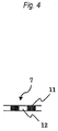
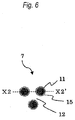
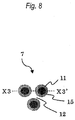
- the conventional hot-air processing machine is a so-called suction band dryer and has a structure where a conveyer is surrounded by a thermal treatment chamber. Therefore, the thermal treatment chamber necessarily becomes a large one and hence treating time is also prolonged. In the case where the treating time is long or in the case where hot-air temperature is much higher than the melting point of the fiber, as shown in Figs. 6 and 7 , by the influence of hot air and the heat from the punching board, on the border between the heat-bonded part 11 and the non-heat-bonded part 12, a mixed part 15 where both parts are mixed each other is generated.
- the nonwoven fabric surface on the conveyer net side becomes a state that the fibers are bonded all over the whole surface, and there is a possibility that the non-heat-bonded part 12 becomes absent.
- the hot air temperature is about the same as the melting temperature of the synthetic fiber
- the nonwoven fabric surface on the conveyer net side tends to be a state where the fibers are not bonded all over the whole surface and thus a point-through-air nonwoven fabric wherein heat-bonded parts of the fibers are formed cannot be obtained in some cases.
- the punching board should be sequentially set in accordance with the movement of the conveyer net at the hot-air processing, the conventional point-through air processing method takes time and labor.
- the present invention provides a processing apparatus for hot-air treatment nonwoven fabric capable of manufacturing a nonwoven fabric wherein fibers are partly heat-bonded, both of bulkiness and flexibility are provided, and fibers other than those at the heat-bonded parts do not lose their function and capable of being utilized as a production machine, as well as a processing method capable of manufacturing the nonwoven fabric. Furthermore, the invention provides an apparatus and a method capable of continuously producing a nonwoven fabric having a stable quality, although an apparatus for hot-air penetration is compact.
- the processing apparatus for hot-air treatment nonwoven fabric can easily produce a point-through-air nonwoven fabric wherein fibers are partly heat-bonded by holding a web or a sheet-like material comprising synthetic fibers between an endless belt with holes and an endless belt for fiber conveyance convey to convey, and passing hot air from a hot-air blowing apparatus through the holes of the endless belt with holes to penetrate through the web or sheet-like material. Since the endless belt with holes and the endless belt for fiber conveyance rotate and run, they enable continuous production. Moreover, since it is not necessary to sequentially set a punching board in case of using the endless belt with holes, working efficiency can be improved. Furthermore, since the hot-air blowing apparatus is arranged on an internal side of the endless belt with holes, it is not necessary to cover the whole conveyer with the thermal treatment chamber. Accordingly, the processing apparatus for hot-air treatment nonwoven fabric can be made compact.
- the processing apparatus for hot-air treatment nonwoven fabric of the invention can produce a point-through-air nonwoven wherein the synthetic fibers at the parts through which the hot air is allowed to penetrate are heat-bonded as tubular films or minute clots near the penetration parts and a point-through-air nonwoven wherein intersecting points of the fibers are heat-bonded, by allowing hot air to penetrate at a temperature equal to or higher than the melting point of the synthetic fiber constituting the web or sheet-like material.
- the processing apparatus for hot-air treatment nonwoven fabric of the invention can be used as an apparatus for the thermal treatment such as annealing by allowing hot air to penetrate or applying hot air at a temperature lower than the melting point of the synthetic fiber constituting the web or sheet-like material.
- the present invention relates to:
- Fig. 1 is a lateral schematic view of the whole apparatus which is exemplified in order to illustrate the processing apparatus for hot-air treatment nonwoven fabric of the invention.
- the processing apparatus for hot-air treatment nonwoven fabric of the present invention comprises an endless belt with holes 1, a hot-air blowing duct (hot-air blowing apparatus) 2, an endless belt for fiber conveyance 3, a hot-air sucking duct (hot-air sucking apparatus) 4, a cooling-air sucking duct (cooling apparatus) 5, a hot-air circulating fan 8, an air heater 9, and an exhaust fan 10.
- the hot-air blowing duct 2 is arranged on an internal side of the endless belt with holes 1 mounted on a rotating roll, and an endless belt for fiber conveyance 3 mounted on a rotating roll is arranged at a side opposite to the hot-air blowing side of the hot-air blowing duct 2 across the endless belt with holes 1 at a predetermined distance from the endless belt with holes 1.
- the hot-air sucking duct 4 is arranged on an internal side of the endless belt for fiber conveyance 3 in a position opposed to the hot-air blowing duct 2, and the cooling-air sucking duct 5 is arranged on a downstream side of the hot-air sucking duct 4, namely, on the rotating direction side of the belt.
- the hot-air circulating fan 8 and the air heater 9 are connected to the hot-air sucking duct 4 and the hot-air blowing duct 2 with a connecting duct, and the exhaust fan 10 is connected to the cooling-air sucking duct 5 with a connecting duct.
- a fiber web (heat-bondable conjugate fiber web) 6 is supplied from the left side, conveyed to the right side in condition of being held between the endless belt with holes 1 and the endless belt for fiber conveyance 3 both of which rotate to run at the same speed, and subjected to a hot-air treatment in the middle of conveyance to form a point-through-air nonwoven fabric 7.
- the hot air supplied from the hot-air blowing duct 2 is applied to the fiber web 6 through the holes of the endless belt with holes 1; synthetic fibers comprised in it are melted mainly at the positions of the holes of the endless belt with holes 1 (web A at hot-air treatment parts) and is cooled in the cooling-air sucking duct 5; the intersecting points of the fibers melted and bonded in the web passing through the cooling-air sucking duct 5 (web B at cooling treatment parts) are gradually solidified as the web's running; the melted parts of the fiber in the web which reaches near an exit (partly heat-bonded web C) are completely solidified to form a partly heat-bonded point-through-air nonwoven fabric 7.
- the processing apparatus for hot-air treatment nonwoven fabric of the invention has a mechanism that the hot air penetrating from the web A at the hot-air treatment parts is sucked from the hot-air sucking duct 4 by the hot-air circulating fan 8 and is continuously sent to the hot-air blowing duct 2 to circulate the hot air. Furthermore, the air heater 9 is provided in the middle of the circulating path of the hot air to control the temperature of the hot air to a temperature equal to or higher than the melting point of the synthetic fiber.
- the apparatus has a mechanism that the cooling-air sucking duct 5 provided on the downstream side of the hot-air sucking duct 4 is connected to the exhaust fan 10, and the atmospheric air penetrates through the endless belt with holes 1, the web B at the cooling treatment parts and the endless belt for fiber conveyance 3 sequentially to force each part and member to cool; is sucked from the sucking port; and exhausted outside.
- Each of the endless belt with holes 1 and the endless belt for fiber conveyance 3 is mounted on rotating rolls and continuously rotate to run. Each running speed is almost the same. It is possible to stably perform processing of the hot-air treatment since the running at the same speed enables no transversal deviation of the fiber constituting the fiber web 6 and no positional deviation of the parts to be subjected to the hot-air treatment parts. Furthermore, it is possible to control quality change of the fiber constituting the point-through-air nonwoven fabric 7 other than the parts subjected to the hot-air treatment parts.
- a driving source may be connected to the rolls on which each belt has been mounted, or transmitted from either one driving source.
- the endless belt with holes 1 is a belt formed to be a circular plate material having a necessary length or formed to be endless in a running direction (hereinafter referred to as MD) by connecting both end parts wherein small holes are made almost all over the whole surface of the belt.
- the length of the belt in MD and the length in a width direction (hereinafter referred to as CD) are not particularly limited. Basically, as long as the functions described in the present specification are satisfied, it is preferred that the lengths in MD and CD are small from the viewpoint of downsizing the processing apparatus for hot-air treatment nonwoven fabric of the invention. That is, the length in MD may be one which is enough to incorporate the individual apparatus explained in the present application and the width in CD may be one which is enough to process the largest width of a desired product without problems.
- the open area ratio of the holes of the endless belt with holes 1 is preferably 60% or less, more preferably 10 to 40%.
- the open area ratio is 60% or less, the ratio of the heat-bonded parts where the fibers are bonded each other in the point-through-air nonwoven fabric 7 is not exceedingly large and the ratio of the non-heat-bonded parts is not exceedingly small. Therefore, when the ratio is 60% or less, since the ratio is kept in an appropriate range, the point-through-air nonwoven fabric 7 becomes rich in flexibility. Also, the fibers at the non-heat-bonded parts, namely, the fibers other than the heat-bonded parts can exhibits the functions sufficiently. Accordingly, by controlling the open area ratio to 64% or less, a point-through-air nonwoven fabric 7 can have bulkiness and flexibility and maintain functions of the fibers other than the heat-bonded parts in good balance can be formed.
- the open area ratio of the endless belt with holes 1 is preferably 60% or less.
- the open area ratio is 60% or less, an apparatus can have sufficient strength and distortion resistance and endure a long-term use as a production apparatus.
- the thickness of the endless belt with holes 1 is riot particularly limited but is preferably 0.3 to 2 mm.
- the belt is excellent in distortion resistance.
- the belt can have flexibility enough to fit the rotating roll.
- the raw material of the endless belt with holes 1 is not particularly limited. However, from the mechanical viewpoint and the viewpoint of nonwoven fabric processability as a production apparatus, it is necessary to possess thermal resistance, thermal distortion resistance, and rust resistance together with high strength and the distortion resistance. Also, the raw material preferably has smoothness as far as possible. Preferable examples of the raw material for the belt include a stainless steel plate, an iron plate subjected to a hard chromium-plating treatment and the like.
- the shape of the hole and area per one hole of the endless belt with holes 1 are not particularly limited and may be suitably selected in consideration of the thickness of the fiber web to be processed.
- the layout of the holes is not particularly limited. However, when the area per hole is extremely large, the obtained nonwoven fabric may be out of the criteria of partial heat-bonding. Moreover, when there is a region where the distance between holes is large, the region may still remain as a web. Therefore, it is impossible to form a nonwoven fabric.
- the holes of the endless belt with holes 1 may be circular ones, elliptical ones, triangular ones, square ones, rectangular ones, hexagonal ones, amorphous ones, and mixtures thereof and also are preferably located almost uniformly all over the whole surface of the belt as far as possible.
- the hot-air blowing duct 2 is a hot-air blowing apparatus in the invention.
- the hot-air blowing duct 2 is arranged close to an internal side of the endless belt with holes 1 and the hot-air blowing face of the hot-air blowing duct 2 is located on the web A side at the hot-air treatment part.
- the distance between the endless belt with holes 1 and the hot-air blowing duct 2 is preferably within 5 mm. By controlling the distance within 5 mm, hot air can be surely allowed to penetrate through the web A at the hot-air treatment part.
- the distance between the hot-air blowing face of the hot-air blowing duct 2 and the internal side of the endless belt with holes 1 can be arbitrarily set by mounting the hot-air blowing duct 2 on a body supporting the endless belt with holes 1 and the rotating rolls on which the belt is mounted in an integrated fashion and providing a mechanism which can control the distance of the mounted portion and the body.
- a frame material having a small frictional resistance may be attached onto an outer frame of the hot-air blowing face as a part of the hot-air blowing apparatus and may be arranged so as to be in contact with the internal side of the endless belt with holes 1.
- the length in MD of the hot-air blowing face of the hot-air blowing duct 2 is not particularly limited. However, it is necessary to decide the length in MD in view of the uniformity of the hot-air blowing rate, the compactness of the apparatus itself and the productivity.
- the running rate of the endless belt with holes 1 high so as to shorten the passing time of the web A at the hot-air treatment part through the hot-air blowing duct 2.
- the running speed of the endless belt with holes 1 low so as to extend the passing time.
- the apparatus so as to control the length in MD of the hot-air blowing face in addition to the processing conditions, such as the above-mentioned running speed of the belt and distance between the endless belt with holes 1 and the endless belt for fiber conveyance 3, the hot-air blowing rate and hot-air temperature to be mentioned later.
- Examples of the method include a method where the part of the hot-air blowing face of the hot-air blowing duct 2 is designed to be separable, various kinds of the part different in the length in MD are assorted and the parts having a necessary length among them is selected and mounted; a method where a sliding damper from the upstream and downstream sides of the hot-air blowing face or either side thereof is mounted and the length is adjusted so as to be necessary length; and the like.
- the length in CD of the hot-air blowing face of the hot-air blowing duct 2 is not particularly limited. Basically, the length may be adjusted so as to be one equivalent to the maximum width of the point-through-air nonwoven fabric 7 to be produced. However, when the width of the point-through-air nonwoven fabric 7 to be produced is small, it is important to adjust the length in CD to the width. That is, the length in CD of the hot-air blowing face is too large relative to the width of the web A at the hot-air treatment part which passes through the site, the hot air tends to flow to both side portions where the web A is not present.
- control of the width in CD may be performed by a method wherein the aforementioned method of controlling the length in MD is applied to CD and developed.
- the hot-air blowing rate of the hot-air blowing face of the hot-air blowing duct 2 is not particularly limited. However, a deviation range of the rate is regulated so as to be preferably 12% or less and more preferably 8% or less in terms of a CV value.
- the definition of the CV value is a variation coefficient of wind velocity. Specially, the value is represented as a percentage which is obtained by dividing standard deviation of each wind velocity by the average velocity thereof wherein the wind velocity is the wind velocity at each intersection points on an imaged grid resulting from sectioning of the whole blowing face from the central part in the directions of MD and CD at intervals of 10 cm.
- an air-inner-pressure elevating apparatus and the like may be provided between the air inlet and the hot-air blowing face of the hot-air blowing duct 2.
- the air-flow-path controlling apparatus, an air-inner-pressure elevating apparatus and the like are effective for decreasing the CV value. They are not particularly necessary in the case where the CD length of the nonwoven fabric to be produced is small; the bulk density is small; or the open area ratio of the endless belt with holes 1 is small. However, it effectively acts in the case where the CD length of the nonwoven fabric to be produced is large; the bulk density is large; or the open area ratio of the endless belt with holes 1 is large.
- the endless belt for fiber conveyance 3 is a belt a belt formed to be a circular plate material having a necessary length or formed to be endless in a running direction (hereinafter referred to as MD) by connecting both end parts wherein openings capable of passing the hot air supplied from the hot-air blowing duct 2 are provided.
- MD running direction
- the MD length and CD length of the endless belt for fiber conveyance 3 are not particularly limited. Basically, as long as the functions described in the present specification are satisfied, a smaller one is preferred from the viewpoint of downsizing the processing apparatus for hot-air treatment nonwoven fabric of the invention.
- the endless belt for fiber conveyance 3 exemplified in the invention is one wherein a fibrous material is formed into a net-like belt by weaving or knitting.
- the shape, size and the like of the openings are not particularly limited as long as the fiber web 6 can be placed and conveyed and the hot air supplied from the hot-air blowing duct 2 can be allowed to penetrate in the blowing direction, i.e., in the thickness direction of the web A at the hot-air treatment part to be passed through the hot-air blowing duct 2 without blocking the flow path.
- the raw material and the fiber diameter are not particularly limited.
- the mode of weaving or knitting, the open area ratio and the like are not particularly limited.
- performances such as strength and thermal resistance for enduring against use, flexibility for following the rotating roll, and air permeability for permeating hot air efficiently are required for the endless belt for fiber conveyance 3. Accordingly, it is necessary to select the fibrous material and the net state so that the performances are satisfied.
- polyesters are used when the operating temperature is about 150°C or less and aromatic polyamides and further stainless steel are used when the operating temperature is more than 150°C.
- a material is preferably performed plain weaving or twill weaving using a fiber having a diameter of about 0.5 to 1.5 mm is preferred.
- a larger open area ratio is preferable in view of securing the permeability of hot air.
- the open area ratio is preferably 30 to 80%.
- the endless belt for fiber conveyance 3 is arranged at a side opposite to the hot-air blowing side of the hot-air blowing duct 2 across the endless belt with holes 1 with providing a predetermined distance.
- the distance between the endless belt with holes 1 and the endless belt for fiber conveyance 3 may be a smaller distance than the thickness of the fiber web 6 to be conveyed.
- the distance is preferably freely controlled in the range of 0.1 to 20 mm. It is preferable that the distance between the endless belt with holes 1 and the endless belt for fiber conveyance 3 is 0.1 mm or more, since the bulkiness of the nonwoven fabric is sufficiently obtained. Also, when the distance between the belts is 20 mm or less, partial heat-bonding of the fiber web can be performed since the hot air partly penetrates.
- the control can be realized by using a mechanism that a body integrally supporting the endless belt with holes 1 and the rotating rolls on which the belt has been mounted and an opposing body integrally supporting the endless belt for fiber conveyance 3 and the rotating rolls on which the belt has been mounted are separately prepared and both bodies or one body can be moved in a distance-controlled fashion against the belt surfaces opposing each other; and using a mechanism for controlling the interval between the bodies.
- the mechanism for the movement in a distance-controlled fashion include a jack-motor method, a hydraulic cylinder method, an air cylinder method and the like.
- the mechanism for controlling the interval include a set pin stopper method capable of freely controlling the length, a position controlling method by a limiter or an optical sensor, and the like.
- the hot-air sucking duct 4 is a hot-air sucking apparatus in the invention.
- the hot-air sucking duct 4 is arranged on an internal side of the endless belt for fiber conveyance so that the hot-air sucking face of the hot-air sucking duct 4 is faced to the web A at the hot-air treatment part and the hot-air sucking face is close to or in contact with the internal side of the endless belt for fiber conveyance 3.
- the hot-air sucking duct 4 is arranged so as to be opposite to the blowing face of the hot-air blowing duct 2 across the web A. Therefore, the hot-air sucking duct 4 sucks the hot air which is supplied from the hot-air blowing duct 2 and penetrated through the endless belt with holes 1, the web A, and the endless belt for fiber conveyance 3.
- the MD and CD lengths of the hot-air sucking face of the hot-air sucking duct 4 are not particularly limited.
- the processing apparatus for hot-air treatment nonwoven fabric has a mechanism of circulating hot air. In order to the hot air efficiently, it is preferred to minimize the introduction of air outside the apparatus which is required for fine control of the hot-air velocity and the hot-air temperature.
- the length may be equal to or slightly larger than the length of the hot-air blowing face of the hot-air blowing duct 2.
- the control of the MD and CD lengths may be performed by a method wherein the above method of controlling the MD and CD lengths of the hot-air blowing face of the hot-air blowing duct 2 is applied and developed.
- the processing apparatus for hot-air treatment nonwoven fabric exemplified in the invention possesses the hot-air circulating fan 8 and the air heater 9.
- the hot-air circulating fan 8 performs supply of blowing air of the hot-air blowing duct (hot-air blowing apparatus) 2 and forced sucking of sucked air of the hot-air sucking duct (hot-air sucking apparatus) 4.
- the air heater 9 is an apparatus for heating the sucked hot air.
- the air-blowing port of the hot-air circulating fan 8 and the air inlet of the hot-air blowing duct 2 are connected with a dedicated connecting duct via the air heater 9 in the midstream.
- the air outlet of the hot-air sucking duct 4 and the air-sucking port of the hot-air circulating fan 8 are connected with a dedicated connecting duct.
- the air supplied by the hot-air circulating fan 8 is heated to a predetermined temperature by the air heater 9 and is supplied to the hot-air blowing duct 2. Then, as mentioned above, the hot air is supplied from the blowing face of the hot-air blowing duct 2, penetrates the web A at the hot-air treatment part, and is sucked from the sucking port of the hot-air sucking duct 4. Thereafter, the hot air is sucked from the air outlet of the hot-air sucking duct 4 to the air sucking port of the hot-air circulating fan 8 and the hot air is circulated with maintaining the predetermined temperature by the repetition thereof.
- the fiber web 6 By continuously supplying the fiber web 6 thereto, it becomes possible to produce the point-through-air nonwoven fabric 7 wherein the fiber is partly heat-bonded.
- the hot-air circulating fan 8 can control the circulating amount per unit time by regulating the number of rotation of the fan and accordingly the passing amount of the hot air passing through the web A at the hot-air treatment part can be inevitably controlled.
- the air heater 9 can be set so as to give a predetermined temperature and the temperature can be set depending on the melting point of the synthetic fiber constituting the fiber web 6.
- the connecting duct is arranged so that the hot air is circulated.
- a hot-air blowing mechanism that a fan dedicated to hot-air blowing is connected to the hot-air blowing duct via an air heater and a hot-air sucking mechanism that a fan dedicated to hot-air sucking is connected to a hot-air sucking duct may be independent from each other.
- only the hot-air blowing mechanism may be used when it has an ability to allowing the hot air to penetrate through the web A and the hot-air sucking mechanism may be not necessary.
- the hot-air blowing mechanism is desirable to make use of the hot-air circulating mechanism.
- the hot-air blowing mechanism independent as mentioned above, it is possible to change the fan dedicated to hot-air blowing as a source for generating hot air into compressed air supplied by a compressor or the like. It is also possible to use pressurized steam in some cases.
- the hot-air blowing rate in these cases can be controlled by pressure control or flow control of air.
- the air heater 9 is necessary from the viewpoint of temperature control, quality maintenance, and stable production.
- the processing apparatus for hot-air treatment nonwoven fabric exemplified in the invention also possesses the cooling-air sucking duct 5 on the downstream side of the hot-air blowing duct (hot-air blowing apparatus) 2.
- the cooling-air sucking duct 5 cools the endless belt with holes 1 heated by the hot-air blowing duct 2 on the upstream side.
- the residual heat of the endless belt with holes 1 itself influences the stability of the melted state of the synthetic fiber constituting the web A at the hot-air treatment part of the hot-air blowing duct 2 and thus continuous homogeneous point-through-air processing cannot be performed.
- an air sucking port of the exhaust fan 10 is connected with a dedicated connecting duct.
- the cooling air penetrates through the holes of the endless belt with holes 1, the web,B at the cooling treatment part, and the openings of the endless belt for fiber conveyance 3 and is sucked from the cooling-air sucking port of the cooling-air sucking duct 5 and exhausted from the exhaust port of the exhaust fan 10.
- the rate of the cooling air can be controlled by changing the number of rotation of the exhaust fan,
- the cooling air exemplified in the invention is not forcibly cooled air but is an atmospheric air located near the belt surface of the endless belt with holes 1 which is an opposite side of the cooling-air sucking port of the cooling-air sucking duct 5.
- the MD length of the cooling-air sucking port is not particularly limited as long as the purpose is achieved.
- the cooling site is any place as long as it is close to the endless belt with holes 1.
- the cooling method of the example is a cooling-air sucking method but the cooling method may be a cooling-air blowing method.
- the cooling apparatus is not necessarily applied.
- a method for spontaneous cooling due to extension of the length of the belt may be applied.
- the apparatus of the invention has an air-forcibly-cooling apparatus that supplies air at a temperature lower than the atmospheric temperature for further enhancing the cooling effect.
- the fiber web 6 runs with being held between the endless belt with holes 1 and the endless belt for fiber conveyance 3, and a part or all of the synthetic fiber constituting the fiber web 6 is melted by hot air from the hot-air blowing duct 2 (web A at the hot-air treatment part) and solidified at the cooling-air sucking duct 5 (web B at the cooling treatment part).
- the fibers which have already formed a partly heat-bonded nonwoven fabric is removed from the apparatus to be the point-through-air nonwoven fabric 7.
- the fiber web 6 to be used in the present application is a synthetic fiber.
- main raw material of the synthetic fiber include thermoplastic resins such as polyethylene, polypropylene, polyethylene terephihalate, Nylon 6, Nylon 66 and polyacrylonitrile.
- the raw material may be so-called biodegradable resins, so-called thermoplastic elastomer resins, and the other copolymer resins, as long as they have thermoplastic properties.
- thermoplastic resin in cross-section of the synthetic fiber is not particularly limited.
- examples thereof include a single cross-section fiber using the above thermoplastic resin as a main raw material, a single cross-section fiber where an auxiliary raw material is mixed into the thermoplastic resin, and a conjugate fiber comprising at least two components of these thermoplastic resins.
- the conjugate fiber comprising two components is preferably a so-called heat-bondable conjugate fiber comprising a low-melting component and a high-melting component and part of the low-melting component forms the fiber surface.
- the cross-sectional shape, fineness, and the like are not particularly limited.
- the fiber web 6 may be constituted by one kind of the synthetic fiber comprising the above raw material and the above cross-section or may be constituted as a mixture of two or more kinds of the synthetic fibers in an almost completely dispersed state.
- the temperature of hot air to be allowed to penetrate through the fiber web 6 comprising such a synthetic fiber at the hot-air blowing duct 2 may be a temperature higher than the lowest melting point among the melting points of the synthetic fibers constituting the web.
- the fiber web 6 comprises the synthetic fiber of one kind of the above conjugate fiber and the penetration temperature of the hot-air is higher than the lowest melting point and lower than the highest melting point, since only the low-melting component is melted and solidified at the hot-air treatment part, a heat-bonded structure by the low-melting component is formed at the intersection points of the fibers which remain as fibrous ones.
- the fiber web 6 comprises at least two kinds of synthetic fibers selected from a single cross-section fiber comprising the above thermoplastic resin as a main raw material, a single cross-section fiber where an auxiliary raw material is mixed into the thermoplastic resin and the above conjugate fiber; and the penetration temperature of the hot-air is higher than the lowest melting point among those of the fiber groups used and lower than the highest melting point, as above, a heat-bonded structure by the low-melting component is formed at the intersecting points of the fibers which remain as fibrous ones.
- the fiber at the hot-air treatment part is melted and heat-bonded in a state where the fibrous shape is lost.
- Example of the heat-bonded in the state where the fibrous shape is lost include the formation of the heat-bonded structure is formed as melted clots at a part of the hot-air treatment part or holes are formed at the hot-air treatment part and the heat-bonded structure is formed as films at the periphery of the holes.
- the process for producing the fiber web 6 is not particularly limited as long as it is a process capable of forming the synthetic fiber into a web shape. Examples thereof include a carding method and dry pulp method for forming a web from short fibers; a spun bond method for forming a web from long fibers: and a melt-blown method for forming a web from fibrous ones obtained by blowing a melted resin with hot air or the like.
- the web obtained by these methods may be processed in a state of a single layer. And the webs may be obtained by the same kind of method or by the same kind of method and by a different method, and then processed in a state of a multilayer web of two or more layers laminated.
- connection between the apparatus for producing the fiber web 6 and the processing apparatus for hot-air treatment nonwoven fabric may be so-called in-line where both of them are sequentially arranged or so-called off-line where both ones are separated.
- all may be in-line or may be off-line where the webs are laminated beforehand.
- the line may be a line where an in-line part and an off-line part are mixed.
- the process for producing the fiber web 6 the kind of the synthetic fiber constituting the fiber web 6, the distance between the endless belt with holes 1 and the endless belt for fiber conveyance 3, the open area ratio of holes of the endless belt with holes 1 and processing conditions such as the hot-air temperature, hot-air velocity, and passing time at the hot-air treatment site, it is possible to produce various kinds of the point-through-air nonwoven fabric 7.
- the hot-air penetration treatment time performed in the processing method in the processing apparatus for hot-air treatment nonwoven fabric is not particularly limited.
- the time is preferably from 0.1 to 10 seconds, and more preferably from 0.3 to 8 seconds.
- the hot-air treatment time is a time for passing the fiber web 6 through the hot-air blowing duct (hot-air blowing apparatus) 2, and the time is necessary to control in view of the relation between the unit weight and the density of the point-through-air nonwoven fabric 7 to be produced, the relation between the hot-air temperature and the bonded state and the like.
- the time to treat the web is as short as possible.
- the hot-air treatment of 0.1 second or more can provide a sufficient amount of heat with the fiber web 6 and the hot-air treatment of 10 seconds or less can suppress the influence of heat to the parts other than the hot-air treatment part.
- the hot-air treatment is performed for more than 10 seconds, since the temperature of the endless belt with holes 1 itself becomes high, a side of the fiber web 6 which is in contact with the endless belt with holes I is wholly influenced by heat. Therefore, the surface of the point-through-air nonwoven fabric 7 tends to become hard and secondary processability tends to be impaired.
- the hot-air penetration treatment time can be set by the MD length of the hot-air blowing face and the running speed.
- the point-through-air nonwoven fabric where the heat-bonded parts are formed in the spots of the fiber web can be produced.
- a web can be treated with hot air in a predetermined position of the belt, it is not necessary to place the whole apparatus under a heat atmosphere. Therefore, it is possible to produce a point-through-air nonwoven fabric where generation of a mixed part of the heat-bonded part and the non-heat-bonded part is suppressed.
- the endless belt with holes and the endless belt for fiber conveyance are rotate to run at the same rate, the position of the holes of the endless belt with holes in contact with the fiber web do not shift and thus partial heat-bonding can be surely achieved.
- the processing apparatus for hot-air treatment nonwoven fabric of the invention can also perform point-through-air processing of a sheet-like material.
- the sheet-like material in the present application include a material processed into a sheet-like one beforehand using a thermoplastic resin which may constitute the above web as a raw material.
- the kind of the constituting fiber and the degree of mixing and the like are not limited. Also, it is not limited to be a monolayer material or a laminated material.
- the bulk density is also not particularly limited. However, in the case where the bulk density is so high that the air permeability is impaired, the hot-air penetration processing becomes difficult, so that the bulk density is desirably 0.5 g/cm 3 or less.
- the present apparatus can also perform point-through-air processing of a laminated material of the sheet-like material and the above web.
- the point-through-air nonwoven fabric obtained by the processing apparatus of the invention can be made so as to have high bulkiness and high air permeability since the web and sheet-like material can be processed without pressing with a high pressure.
- by controlling the thickness it is possible to arbitrarily control bulk density, air permeability and the like.
- the above processing apparatus for hot-air treatment nonwoven fabric and processing method are effective for manufacturing a nonwoven fabric having all of bulkiness, flexibility, air permeability and strength. Furthermore, since the processing apparatus and the processing method enable the processing without losing properties of synthetic fiber, the nonwoven fabric processed by this method can be easily subjected to secondary processing utilizing properties of the synthetic fiber and sheet-like material.
- the nonwoven fabric obtained by the processing apparatus for hot-air treatment nonwoven fabric and processing method of the invention is excellent in bulkiness, flexibility, and air permeability; also has high-strength; and can utilize properties of the synthetic fiber constituting the web before processing and the sheet-like material before processing
- the nonwoven fabric is suitably used for surface members for disposal diapers; surface members for hygienic materials such as members for sanitary goods; stretchable members for hygienic materials such as stretchable members for disposal diapers, stretchable members for diapers, stretchable members for sanitary goods, and stretchable members for diaper covers; stretchable tapes; adhesive plasters; stretchable members for clothes; interlining cloths for clothing materials; insulating materials and heat-keeping materials for clothing materials; protective clothing; hats and caps; masks; gloves; supporters; stretchable bandages; base fabrics for poultices; base fabrics for plaster materials; antislip base fabrics; vibration absorbers; fingerstalls; various filters such as air filters for clean rooms, blood filters, and filters for oily water separation;
- a point-through-air nonwoven fabric where the fiber was partly heat-bonded was processed.
- the web in Example 1 was continuously processed using a carding machine used in the previous step (not shown in figure) and then supplied to the processing apparatus for hot-air treatment nonwoven fabric of Fig. 1 .
- the web has a unit weight of 30 g/m 2 and a width of 1 m.
- the endless belt with holes 1 is made of stainless steel and holes are made all over the surface in a zigzag arrangement with a hole diameter of 2.5 mm and at the intervals of 5 mm.
- the open area ratio is 22.7%.
- the endless belt for fiber conveyance 3 is made of polyester and is a plain-woven one having a diameter of monofilament of 1 mm, a warp pitch of 2.5 mm, and a weft pitch of 2.5 mm.
- the open area ratio is 36%.
- the distance between the endless belt with holes 1 and the endless belt for fiber conveyance 3 was set so as to be 2 mm. In addition, the running rates of both belts were set at 50 m/minute.
- the hot-air blowing face of the hot-air blowing duct 2 and the sucking face of the hot-air sucking duct 4 had an MD length of 1 m and a CD length of 1 m and were set so that the faces were opposed to each other.
- the number of rotation of the hot-air circulating fan 8 and the heater temperature of the air heater 9 were set so that hot air supplied from the holes of the endless belt with holes 1 had a temperature of 140°C and an air velocity of 2 m/second.
- the CV value of the air velocity at the hot-air blowing face was measured beforehand and was confirmed to be 7.3%.
- the sucking face of the cooling-air sucking duct 5 had an MD length of 1 m and the CD length was set at 1 m that is equal to the blowing face of the hot-air blowing duct 2 at the upstream side. Moreover, the number of rotation of the cooling-air exhaust fan 10 was set so that the sucking air velocity at the opposed side of the net-like belt in contact with the sucking face of the cooling-air sucking duct 5 was 2 m/second.
- the carding machine and the processing apparatus for hot-air treatment nonwoven fabric were run and the fiber web 6 was supplied to the processing apparatus for hot-air treatment nonwoven fabric of Fig. 1 from the left.
- the web 6 was run at a running rate of 50 m/minute from left to right direction with being held between the endless belt with holes 1 and the endless belt for fiber conveyance 3 without shifting from the belts to continuously produce the point-through-air nonwoven fabric 7 where the parts treated with hot air were heat-bonded.
- the hot-air penetration treatment time is 1.2 second.
- the processing apparatus run continuously for about 6 hours, it could run without generating problems on the apparatus, problems on running and problems on products.
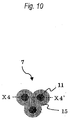
- the produced point-through-air nonwoven fabric 7 kept at a constant thickness of about 2 mm, had the heat-bonded part 11 and the non-heat-bonded part 12 as shown in Figs. 2 , 3 , and 4 and also had both of bulkiness and flexibility.
- a bilayer web which comprised a web having a unit weight of 20 g/m 2 as the upper layer part comprising a sheath-core type conjugate short fiber where the sheath component comprised linear low-density polyethylene having a melting point of 100°C and the core component comprised polypropylene having a melting point of 162°C; fineness was 2 dtex/f; and cut length was 51 mm, and a web having a unit weight of 10 g/m 2 as the lower layer part and comprising a side-by-side type conjugate short fiber wherein the side-by-side type conjugate short fiber comprised ethylenepropylene copolymer having a melting point of 130°C and polypropylene having a melting point of 160°C; fineness was 3 dtex/f; and cut length was 51 mm, a point-through-air nonwoven fabric where only the conjugate fiber constituting the upper layer part was partly heat-bonded was processed.
- the bilayer web in Example 2 was continuously processed using two carding machines which were arranged sequentially and used in the previous step (not shown in figure) and then supplied to the processing apparatus for hot-air treatment nonwoven fabric of Fig. 1 .
- the bilayer web has a unit weight of 30 g/m 2 and a width of 1 m.
- Example 2 The same processing apparatus for hot-air treatment nonwoven fabric as Example 1 was used. However, the processing conditions were as follows. The distance between the endless belt with holes 1 and the endless belt for fiber conveyance 3 was set so as to be 1 mm. The running rate of both belts was set at 50 m/minute which was the same as in Example 1. The temperature of hot air supplied from the holes of the endless belt with holes 1 was set at 120°C in the absence of any web and an air velocity was set at 2 m/second. The sucking air velocity of the cooling air was set at 2 m/second.
- the carding machines and the processing apparatus for hot-air treatment nonwoven fabric were run and the fiber web 6 was supplied to the processing apparatus for hot-air treatment nonwoven fabric of Fig. 1 from the left.
- the web 6 was run at a running rate of 50 m/minute from the left to right direction with being held between the endless belt with holes 1 and the endless belt for fiber conveyance 3 without shifting from the belts to continuously produce a point-through-air nonwoven fabric 7 where only the upper layer part of the part treated with hot air was heat-bonded.
- the apparatus run continuously for 6 hours, it could run without generating problems on the apparatus, problems on running and problems on products.
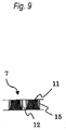
- the produced point-through-air nonwoven fabric 7 kept at a constant thickness of about 1 mm and had the heat-bonded part 11 and the non-heat-bonded part 12 in the upper layer part 13 and the wholly non-heat-bonded part 12 in the lower layer part 14 as shown in Figs. 2 , 3 , and 5 .
- fine crimps of the constituting side-by-side type conjugate fiber were shown at the parts through which hot air penetrated.
- the point-through-air nonwoven fabric 7 was thermally treated at 120°C using a floating drier (not shown in the figure) in the later step.
- the nonwoven fabric was subjected to heat-shrinking processing so as to give a MD shrinking ratio of 50% and a CD shrinking ratio of 40%,
- the nonwoven fabric had a unit weight of 100 g/m 2 and a thickness of about 4 mm and had both of bulkiness and flexibility.
Landscapes
- Engineering & Computer Science (AREA)
- Textile Engineering (AREA)
- Nonwoven Fabrics (AREA)
- Treatment Of Fiber Materials (AREA)
Claims (11)
- Verarbeitungsvorrichtung zur Produktion eines Punkt-durch-Luft-Vliesstoffes, wobei Heißluft gestattet ist, Stellen einer Bahn mit Kunstfasern oder eines bogenartigen Artikels mit Kunstfasern zu durchdringen, und wobei Fasern an den Durchdringungsplätzen thermisch verbunden sind,
dadurch gekennzeichnet, dass sie aufweist:einen sich drehenden, laufenden Endlosriemen mit Löchern (1),eine Heißluft-Blasvorrichtung (2), welche Heißluft von einer Innenseite des Endlosriemens mit Löchern zu einer Außenseite davon hin herausbläst,einen Endlosriemen zur Faserförderung (3), welcher auf einer Seite gegenüberliegend zu der Heißluft-Blasseite der Heißluft-Blasvorrichtung über den Endlosriemen mit Löchern angeordnet ist, und sich mit einem Hindurchführen der Heißluft dreht, undeine Heißluft-Saugvorrichtung (4), welche einen Teil oder sämtliche Menge der von der Heißluft-Blasvorrichtung zugeführten Heißluft saugt, auf einer Innenseite des Endlosriemens zur Faserförderung,wobei die Verarbeitungsvorrichtung imstande ist, einen Punkt-durch-Luft-Vliesstoff zu produzieren, wobei Fasern teilweise wärmeverbunden sind, durch Halten der Bahn oder des bogenartigen Materials mit Kunstfasern zwischen dem Endlosriemen mit Löchern und dem Endlosriemen zur Faserförderung und Durchführen von Heißluft von der Heißluft-Blasvorrichtung durch die Löcher des Endlosriemens mit Löchern, um die Bahn oder das bogenartige Material zu durchdringen. - Verarbeitungsvorrichtung zur Heißluftbehandlung von Vliesstoff nach Anspruch 1, wobei der Endlosriemen mit Löchern und der Endlosriemen zur Faserförderung einen Abstand aufweist, welcher in dem Bereich von 0,1 bis 20 mm frei steuerbar ist.
- Verarbeitungsvorrichtung zur Heißluftbehandlung von Vliesstoff nach Anspruch 1 oder 2, wobei der Endlosriemen mit Löchern ein Verhältnis des offenen Bereichs von 60% oder weniger aufweist.
- Verarbeitungsvorrichtung zur Heißluftbehandlung von Vliesstoff nach Anspruch 1 oder 2, wobei der Endlosriemen mit Löchern ein Verhältnis des offenen Bereichs von 10 bis 40% aufweist.
- Verarbeitungsvorrichtung zur Heißluftbehandlung von Vliesstoff nach einem der Ansprüche 1 bis 4, wobei die Heißluft-Blasvorrichtung einen CV-Wert einer Heißluft-Blasrate von 12% oder weniger aufweist.
- Verarbeitungsvorrichtung zur Heißluftbehandlung von Vliesstoff nach einem der Ansprüche 1 bis 5, ferner mit einer Kühlvorrichtung (5), die den Endlosriemen mit Löchern kühlt.
- Verfahren zur Produktion eines Punkt-durch-Luft-Vliesstoffes, wobei Heißluft gestattet ist, Stellen einer Bahn mit Kunstfasern oder eines bogenartigen Artikels mit Kunstfasern zu durchdringen, und wobei Fasern an den Durchdringungsplätzen thermisch verbunden werden, umfassend ein Durchdringen von Heißluft durch zumindest eine Schicht der Bahn oder des bogenartigen Materials, welche/s zumindest eine Kunstfaser für eine thermische Behandlung umfasst, unter Verwendung der Verarbeitungsvorrichtung zur Heißluftbehandlung von Vliesstoff nach einem der Ansprüche 1 bis 6, um einen Punkt-durch-Luft-Vliesstoff zu produzieren, wobei Fasern teilweise wärmeverbunden werden, durch Halten der Bahn oder des bogenartigen Materials mit Kunstfasern zwischen dem Endlosriemen mit Löchern und dem Endlosriemen zur Faserförderung und Durchführen von Heißluft von der Heißluft-Blasvorrichtung durch die Löcher des Endlosriemens mit Löchern, um die Bahn oder das bogenartige Material zu durchdringen.
- Verfahren zur Verarbeitung eines Punkt-durch-Luft-Vliesstoffes nach Anspruch 7, wobei die Heißluft gleich dem oder höher als der niedrigste Schmelzpunkt unter den Kunstfasern ist.
- Verfahren zur Produktion eines Punkt-durch-Luft-Vliesstoffes nach Anspruch 8, wobei die Kunstfasern an den Teilen, durch welche der Heißluft ein Durchdringen gestattet wird, als röhrenförmige Filme oder winzige Klumpen nahe den Durchdringungsteilen wärmeverbunden werden, und ein Punktdurch-Luft-Vliesstoff produziert wird, wobei Schnittpunkte der Fasern wärmeverbunden werden, dadurch dass Heißluft gestattet wird, bei einer Temperatur gleich dem oder höher als der Schmelzpunkt der Kunstfaser, welche die Bahn oder das bogenartige Material bildet, zu durchdringen.
- Verfahren zur Produktion eines Punkt-durch-Luft-Vliesstoffes nach Anspruch 7, 8 oder 9, wobei zumindest eine Art der Kunstfasern eine Konjugatfaser mit zwei oder mehr sich im Schmelzpunkt unterscheidenden Komponenten ist.
- Verfahren zur Produktion eines Punkt-durch-Luft-Vliesstoffes nach einem der Ansprüche 7 bis 10, wobei ein Zeitraum für die Behandlung, um Heißluft durch die Bahn oder das bogenartige Material zu durchdringen, von 0,1 bis 10 Sekunden beträgt.
Applications Claiming Priority (1)
| Application Number | Priority Date | Filing Date | Title |
|---|---|---|---|
| JP2010086394A JP5477123B2 (ja) | 2010-04-02 | 2010-04-02 | 熱風処理不織布加工装置および加工方法 |
Publications (2)
| Publication Number | Publication Date |
|---|---|
| EP2372005A1 EP2372005A1 (de) | 2011-10-05 |
| EP2372005B1 true EP2372005B1 (de) | 2016-10-05 |
Family
ID=43921031
Family Applications (1)
| Application Number | Title | Priority Date | Filing Date |
|---|---|---|---|
| EP11160398.1A Not-in-force EP2372005B1 (de) | 2010-04-02 | 2011-03-30 | Verarbeitungsvorrichtung zur Heißluftbehandlung aus faserersetzendem Vliesstoff zur Herstellung von Vliesstoff, und Verarbeitungsverfahren dafür |
Country Status (5)
| Country | Link |
|---|---|
| US (1) | US9481954B2 (de) |
| EP (1) | EP2372005B1 (de) |
| JP (1) | JP5477123B2 (de) |
| CN (1) | CN102212935B (de) |
| TW (1) | TWI618830B (de) |
Cited By (1)
| Publication number | Priority date | Publication date | Assignee | Title |
|---|---|---|---|---|
| EP3825449B1 (de) | 2016-03-24 | 2022-10-26 | Beaulieu International Group NV | Teppich umfassend eine vliesstruktur mit durch einen metallocenkatalysator katalysierten fasern |
Families Citing this family (22)
| Publication number | Priority date | Publication date | Assignee | Title |
|---|---|---|---|---|
| CN102747537B (zh) * | 2011-12-20 | 2015-07-22 | 金红叶纸业集团有限公司 | 一种复合无纺布固结设备及工艺 |
| CN102535010B (zh) * | 2011-12-23 | 2014-09-03 | 金红叶纸业集团有限公司 | 复合无纺布吸收体生产设备、工艺及复合无纺布吸收体 |
| JP6024915B2 (ja) * | 2013-03-28 | 2016-11-16 | Jnc株式会社 | 不織布およびそれを用いて得られた製品 |
| CN103806222A (zh) * | 2014-03-10 | 2014-05-21 | 宋志敏 | 一种多组分一次成型热风无纺布及其制造方法 |
| KR102302375B1 (ko) | 2014-08-27 | 2021-09-15 | 도레이 카부시키가이샤 | 멜트 블로 부직포 및 그 제조 방법 |
| CN105568560A (zh) * | 2014-10-08 | 2016-05-11 | 张家港骏马无纺布有限公司 | 一种蓬松熔喷布的制备方法 |
| CN104514139A (zh) * | 2014-12-24 | 2015-04-15 | 江苏海狮机械集团有限公司 | 用于运送湿布草的进料输送装置 |
| EP3406780B1 (de) * | 2017-05-22 | 2020-01-08 | Axel Nickel | Getemperter meltblown-vliesstoff mit hoher stauchhärte |
| US20200139282A1 (en) * | 2017-05-30 | 2020-05-07 | Toray Industries, Inc. | Spunbond non-woven fabric for filter and method of manufacturing said fabric |
| EP3714086A4 (de) | 2017-11-22 | 2021-10-06 | Extrusion Group, LLC | Schmelzblasdüsenspitzenanordnung und -verfahren |
| US10946412B2 (en) * | 2018-03-19 | 2021-03-16 | Ronie Reuben | Thermally insulating sheet formed from a down core structure and method of fabrication |
| CN110016767B (zh) * | 2019-04-10 | 2020-10-16 | 武汉纺织大学 | 喷气固结式高吸附非织造布的制备方法及高吸附非织造布 |
| CN111334927A (zh) * | 2019-04-10 | 2020-06-26 | 浙江艾伦新材料有限公司 | 一种气流固结成形的高弹填充材料及其制备方法 |
| ES2911184T3 (es) * | 2019-07-30 | 2022-05-18 | Reifenhaeuser Masch | Dispositivo y procedimiento para producir un material no tejido |
| CN113622085A (zh) * | 2020-05-07 | 2021-11-09 | 新丽企业股份有限公司 | 可调密度的纤维结构体的制造装置及方法 |
| KR102222357B1 (ko) * | 2020-06-26 | 2021-03-04 | 김민호 | 부직포 제조장치 |
| CN112030358B (zh) * | 2020-09-16 | 2024-11-26 | 河北恒永滤材科技有限公司 | 一种熔喷无纺布连续水刺驻极装置 |
| CN112408058B (zh) * | 2020-10-26 | 2022-08-09 | 温州市锦源合成纤维有限公司 | 一种无纺布加工设备 |
| WO2023286140A1 (ja) * | 2021-07-12 | 2023-01-19 | 花王株式会社 | 不織布の製造方法、これにより製造された不織布、及び該不織布を構成部材として含む吸収性物品 |
| CN114134666B (zh) * | 2021-12-06 | 2024-06-04 | 江苏润云纺织科技有限公司 | 一种织布定型机用冷却装置 |
| CN115323698A (zh) * | 2022-08-31 | 2022-11-11 | 宁波海世纺织科技有限公司 | 一种面料加工用熨烫装置 |
| CN117306164A (zh) * | 2023-10-18 | 2023-12-29 | 福建省金嘉华卫生用品有限公司 | 一种纸尿裤用膨松无纺布的制备方法 |
Citations (1)
| Publication number | Priority date | Publication date | Assignee | Title |
|---|---|---|---|---|
| JPH08226069A (ja) * | 1995-02-23 | 1996-09-03 | Watanabe Eng Kk | 繊維製品熱処理成形機 |
Family Cites Families (18)
| Publication number | Priority date | Publication date | Assignee | Title |
|---|---|---|---|---|
| BE617864A (de) | 1961-05-29 | |||
| JPS5137389B2 (de) * | 1971-08-12 | 1976-10-15 | ||
| JPS57205569A (en) * | 1981-06-05 | 1982-12-16 | Asahi Chemical Ind | Method and apparatus for producing nonwoven fabric |
| US4642153A (en) * | 1983-05-31 | 1987-02-10 | Allen Industries, Inc. | Method and apparatus for making a sheet of material |
| JPH0635697B2 (ja) * | 1984-10-05 | 1994-05-11 | 井上金属工業株式会社 | 不織布製造方法及び不織布製造装置 |
| JP2800841B2 (ja) * | 1990-05-17 | 1998-09-21 | 花王株式会社 | 不織布及びその製造方法並びに吸収性物品 |
| JPH04343748A (ja) * | 1991-05-21 | 1992-11-30 | Nippon Filcon Co Ltd | 不織布製造用ベルト及び模様を形成した不織布の製造方法 |
| JP3109630B2 (ja) * | 1992-11-06 | 2000-11-20 | チッソ株式会社 | 不織布の製造方法 |
| JP3365520B2 (ja) * | 1993-09-01 | 2003-01-14 | 東洋紡績株式会社 | 繊維集合体の熱処理方法および装置 |
| DE19714348C2 (de) * | 1997-03-26 | 2001-06-07 | Rudolf Grafe | Verfahren zur Herstellung von Dämmstoffen aus Textilabfällen, danach hergestellte Dämmstoffe und Verwendung derselben |
| US6010323A (en) * | 1997-04-11 | 2000-01-04 | Masaki Ooba | Vacuum pressure forming apparatus and vacuum pressure forming method |
| DE19740338A1 (de) * | 1997-09-13 | 1999-03-18 | Truetzschler Gmbh & Co Kg | Vorrichtung zum Herstellen eines Faservlieses, z. B. aus Baumwolle, Chemiefasern, Fasermischungen u. dgl. |
| JP4206570B2 (ja) * | 1999-04-23 | 2009-01-14 | チッソ株式会社 | 不織布およびそれを用いた吸収性物品 |
| GB0128692D0 (en) | 2001-11-30 | 2002-01-23 | B & H Res Ltd | Formation of sheet material using hydroentanglement |
| JP4747259B2 (ja) | 2005-09-22 | 2011-08-17 | Jnc株式会社 | 嵩高柔軟性不織布及びそれを用いた繊維製品 |
| JP5123497B2 (ja) | 2006-06-23 | 2013-01-23 | ユニ・チャーム株式会社 | 不織布、不織布製造方法及び不織布製造装置 |
| CN102036595A (zh) * | 2008-05-27 | 2011-04-27 | 花王株式会社 | 清扫用片材的制造方法 |
| JP4762289B2 (ja) | 2008-10-01 | 2011-08-31 | 株式会社日立製作所 | 特定パターンデータが格納される仮想ボリュームへの記憶領域の割り当てを制御するストレージシステム |
-
2010
- 2010-04-02 JP JP2010086394A patent/JP5477123B2/ja active Active
-
2011
- 2011-03-30 US US13/075,969 patent/US9481954B2/en not_active Expired - Fee Related
- 2011-03-30 CN CN201110083602.4A patent/CN102212935B/zh active Active
- 2011-03-30 TW TW100111046A patent/TWI618830B/zh not_active IP Right Cessation
- 2011-03-30 EP EP11160398.1A patent/EP2372005B1/de not_active Not-in-force
Patent Citations (1)
| Publication number | Priority date | Publication date | Assignee | Title |
|---|---|---|---|---|
| JPH08226069A (ja) * | 1995-02-23 | 1996-09-03 | Watanabe Eng Kk | 繊維製品熱処理成形機 |
Cited By (1)
| Publication number | Priority date | Publication date | Assignee | Title |
|---|---|---|---|---|
| EP3825449B1 (de) | 2016-03-24 | 2022-10-26 | Beaulieu International Group NV | Teppich umfassend eine vliesstruktur mit durch einen metallocenkatalysator katalysierten fasern |
Also Published As
| Publication number | Publication date |
|---|---|
| EP2372005A1 (de) | 2011-10-05 |
| US20110240210A1 (en) | 2011-10-06 |
| CN102212935A (zh) | 2011-10-12 |
| JP2011219873A (ja) | 2011-11-04 |
| US9481954B2 (en) | 2016-11-01 |
| CN102212935B (zh) | 2015-05-06 |
| TW201134997A (en) | 2011-10-16 |
| JP5477123B2 (ja) | 2014-04-23 |
| TWI618830B (zh) | 2018-03-21 |
Similar Documents
| Publication | Publication Date | Title |
|---|---|---|
| EP2372005B1 (de) | Verarbeitungsvorrichtung zur Heißluftbehandlung aus faserersetzendem Vliesstoff zur Herstellung von Vliesstoff, und Verarbeitungsverfahren dafür | |
| EP1348051B1 (de) | In-line-wärmebehandlung von gekräuselten homofilament-fasern | |
| CA2208890C (en) | Method for producing a nonwoven web | |
| CA2270529C (en) | Entangled nonwoven fabrics and methods for forming the same | |
| KR100743215B1 (ko) | 높은 가로방향 신도를 갖는 개선된 부직포 및 그것의제조방법 | |
| US6066221A (en) | Method of using zoned hot air knife | |
| EP0418493A1 (de) | Ein nicht-gewebter zusammengesetzter durch Hydro-Verwirrung verbundener Stoff und ein Verfahren zu seiner Herstellung | |
| JPS6051586B2 (ja) | 不織布の製造方法および装置 | |
| JPWO1988009838A1 (ja) | 経緯伸縮性布帛及びその製造方法 | |
| CA2313354C (en) | Process for making elastically stretchable composite sheet | |
| KR20200033898A (ko) | 선택적 배기를 갖는 단열 구조체 | |
| US7025914B2 (en) | Multilayer approach to producing homofilament crimp spunbond | |
| EP1360357B1 (de) | Wasserstrahlverwirbelung endloser polymerfilamente | |
| US20050197027A1 (en) | Bloused spunbond laminate | |
| KR102813753B1 (ko) | 폴리프로필렌 이형단면사를 적용한 후크 체결부재용 스펀본드 장섬유 부직포 루프 | |
| JPH07115436B2 (ja) | 繊維製クッション材の製造方法 | |
| MXPA97004659A (en) | Method for producing a non tram tissue | |
| MXPA98004552A (en) | Zonific hot air blade |
Legal Events
| Date | Code | Title | Description |
|---|---|---|---|
| PUAI | Public reference made under article 153(3) epc to a published international application that has entered the european phase |
Free format text: ORIGINAL CODE: 0009012 |
|
| AK | Designated contracting states |
Kind code of ref document: A1 Designated state(s): AL AT BE BG CH CY CZ DE DK EE ES FI FR GB GR HR HU IE IS IT LI LT LU LV MC MK MT NL NO PL PT RO RS SE SI SK SM TR |
|
| AX | Request for extension of the european patent |
Extension state: BA ME |
|
| RAP1 | Party data changed (applicant data changed or rights of an application transferred) |
Owner name: JNC FIBERS CORPORATION Owner name: CHISSO CORPORATION |
|
| 17P | Request for examination filed |
Effective date: 20120405 |
|
| RAP1 | Party data changed (applicant data changed or rights of an application transferred) |
Owner name: JNC FIBERS CORPORATION Owner name: JNC CORPORATION |
|
| 17Q | First examination report despatched |
Effective date: 20140723 |
|
| GRAP | Despatch of communication of intention to grant a patent |
Free format text: ORIGINAL CODE: EPIDOSNIGR1 |
|
| INTG | Intention to grant announced |
Effective date: 20160429 |
|
| GRAS | Grant fee paid |
Free format text: ORIGINAL CODE: EPIDOSNIGR3 |
|
| GRAA | (expected) grant |
Free format text: ORIGINAL CODE: 0009210 |
|
| AK | Designated contracting states |
Kind code of ref document: B1 Designated state(s): AL AT BE BG CH CY CZ DE DK EE ES FI FR GB GR HR HU IE IS IT LI LT LU LV MC MK MT NL NO PL PT RO RS SE SI SK SM TR |
|
| REG | Reference to a national code |
Ref country code: GB Ref legal event code: FG4D |
|
| REG | Reference to a national code |
Ref country code: CH Ref legal event code: EP |
|
| REG | Reference to a national code |
Ref country code: AT Ref legal event code: REF Ref document number: 834781 Country of ref document: AT Kind code of ref document: T Effective date: 20161015 |
|
| REG | Reference to a national code |
Ref country code: IE Ref legal event code: FG4D |
|
| REG | Reference to a national code |
Ref country code: DE Ref legal event code: R096 Ref document number: 602011030891 Country of ref document: DE |
|
| REG | Reference to a national code |
Ref country code: NL Ref legal event code: MP Effective date: 20161005 |
|
| REG | Reference to a national code |
Ref country code: LT Ref legal event code: MG4D |
|
| PG25 | Lapsed in a contracting state [announced via postgrant information from national office to epo] |
Ref country code: LV Free format text: LAPSE BECAUSE OF FAILURE TO SUBMIT A TRANSLATION OF THE DESCRIPTION OR TO PAY THE FEE WITHIN THE PRESCRIBED TIME-LIMIT Effective date: 20161005 |
|
| REG | Reference to a national code |
Ref country code: AT Ref legal event code: MK05 Ref document number: 834781 Country of ref document: AT Kind code of ref document: T Effective date: 20161005 |
|
| PG25 | Lapsed in a contracting state [announced via postgrant information from national office to epo] |
Ref country code: SE Free format text: LAPSE BECAUSE OF FAILURE TO SUBMIT A TRANSLATION OF THE DESCRIPTION OR TO PAY THE FEE WITHIN THE PRESCRIBED TIME-LIMIT Effective date: 20161005 Ref country code: GR Free format text: LAPSE BECAUSE OF FAILURE TO SUBMIT A TRANSLATION OF THE DESCRIPTION OR TO PAY THE FEE WITHIN THE PRESCRIBED TIME-LIMIT Effective date: 20170106 Ref country code: LT Free format text: LAPSE BECAUSE OF FAILURE TO SUBMIT A TRANSLATION OF THE DESCRIPTION OR TO PAY THE FEE WITHIN THE PRESCRIBED TIME-LIMIT Effective date: 20161005 Ref country code: NO Free format text: LAPSE BECAUSE OF FAILURE TO SUBMIT A TRANSLATION OF THE DESCRIPTION OR TO PAY THE FEE WITHIN THE PRESCRIBED TIME-LIMIT Effective date: 20170105 |
|
| PG25 | Lapsed in a contracting state [announced via postgrant information from national office to epo] |
Ref country code: BE Free format text: LAPSE BECAUSE OF FAILURE TO SUBMIT A TRANSLATION OF THE DESCRIPTION OR TO PAY THE FEE WITHIN THE PRESCRIBED TIME-LIMIT Effective date: 20161005 Ref country code: PL Free format text: LAPSE BECAUSE OF FAILURE TO SUBMIT A TRANSLATION OF THE DESCRIPTION OR TO PAY THE FEE WITHIN THE PRESCRIBED TIME-LIMIT Effective date: 20161005 Ref country code: FI Free format text: LAPSE BECAUSE OF FAILURE TO SUBMIT A TRANSLATION OF THE DESCRIPTION OR TO PAY THE FEE WITHIN THE PRESCRIBED TIME-LIMIT Effective date: 20161005 Ref country code: ES Free format text: LAPSE BECAUSE OF FAILURE TO SUBMIT A TRANSLATION OF THE DESCRIPTION OR TO PAY THE FEE WITHIN THE PRESCRIBED TIME-LIMIT Effective date: 20161005 Ref country code: AT Free format text: LAPSE BECAUSE OF FAILURE TO SUBMIT A TRANSLATION OF THE DESCRIPTION OR TO PAY THE FEE WITHIN THE PRESCRIBED TIME-LIMIT Effective date: 20161005 Ref country code: IS Free format text: LAPSE BECAUSE OF FAILURE TO SUBMIT A TRANSLATION OF THE DESCRIPTION OR TO PAY THE FEE WITHIN THE PRESCRIBED TIME-LIMIT Effective date: 20170205 Ref country code: RS Free format text: LAPSE BECAUSE OF FAILURE TO SUBMIT A TRANSLATION OF THE DESCRIPTION OR TO PAY THE FEE WITHIN THE PRESCRIBED TIME-LIMIT Effective date: 20161005 Ref country code: PT Free format text: LAPSE BECAUSE OF FAILURE TO SUBMIT A TRANSLATION OF THE DESCRIPTION OR TO PAY THE FEE WITHIN THE PRESCRIBED TIME-LIMIT Effective date: 20170206 Ref country code: HR Free format text: LAPSE BECAUSE OF FAILURE TO SUBMIT A TRANSLATION OF THE DESCRIPTION OR TO PAY THE FEE WITHIN THE PRESCRIBED TIME-LIMIT Effective date: 20161005 Ref country code: NL Free format text: LAPSE BECAUSE OF FAILURE TO SUBMIT A TRANSLATION OF THE DESCRIPTION OR TO PAY THE FEE WITHIN THE PRESCRIBED TIME-LIMIT Effective date: 20161005 |
|
| REG | Reference to a national code |
Ref country code: DE Ref legal event code: R097 Ref document number: 602011030891 Country of ref document: DE |
|
| PG25 | Lapsed in a contracting state [announced via postgrant information from national office to epo] |
Ref country code: SK Free format text: LAPSE BECAUSE OF FAILURE TO SUBMIT A TRANSLATION OF THE DESCRIPTION OR TO PAY THE FEE WITHIN THE PRESCRIBED TIME-LIMIT Effective date: 20161005 Ref country code: DK Free format text: LAPSE BECAUSE OF FAILURE TO SUBMIT A TRANSLATION OF THE DESCRIPTION OR TO PAY THE FEE WITHIN THE PRESCRIBED TIME-LIMIT Effective date: 20161005 Ref country code: EE Free format text: LAPSE BECAUSE OF FAILURE TO SUBMIT A TRANSLATION OF THE DESCRIPTION OR TO PAY THE FEE WITHIN THE PRESCRIBED TIME-LIMIT Effective date: 20161005 Ref country code: CZ Free format text: LAPSE BECAUSE OF FAILURE TO SUBMIT A TRANSLATION OF THE DESCRIPTION OR TO PAY THE FEE WITHIN THE PRESCRIBED TIME-LIMIT Effective date: 20161005 Ref country code: RO Free format text: LAPSE BECAUSE OF FAILURE TO SUBMIT A TRANSLATION OF THE DESCRIPTION OR TO PAY THE FEE WITHIN THE PRESCRIBED TIME-LIMIT Effective date: 20161005 |
|
| PLBE | No opposition filed within time limit |
Free format text: ORIGINAL CODE: 0009261 |
|
| STAA | Information on the status of an ep patent application or granted ep patent |
Free format text: STATUS: NO OPPOSITION FILED WITHIN TIME LIMIT |
|
| PG25 | Lapsed in a contracting state [announced via postgrant information from national office to epo] |
Ref country code: IT Free format text: LAPSE BECAUSE OF FAILURE TO SUBMIT A TRANSLATION OF THE DESCRIPTION OR TO PAY THE FEE WITHIN THE PRESCRIBED TIME-LIMIT Effective date: 20161005 Ref country code: BG Free format text: LAPSE BECAUSE OF FAILURE TO SUBMIT A TRANSLATION OF THE DESCRIPTION OR TO PAY THE FEE WITHIN THE PRESCRIBED TIME-LIMIT Effective date: 20170105 Ref country code: SM Free format text: LAPSE BECAUSE OF FAILURE TO SUBMIT A TRANSLATION OF THE DESCRIPTION OR TO PAY THE FEE WITHIN THE PRESCRIBED TIME-LIMIT Effective date: 20161005 |
|
| 26N | No opposition filed |
Effective date: 20170706 |
|
| REG | Reference to a national code |
Ref country code: CH Ref legal event code: PL |
|
| GBPC | Gb: european patent ceased through non-payment of renewal fee |
Effective date: 20170330 |
|
| PG25 | Lapsed in a contracting state [announced via postgrant information from national office to epo] |
Ref country code: MC Free format text: LAPSE BECAUSE OF FAILURE TO SUBMIT A TRANSLATION OF THE DESCRIPTION OR TO PAY THE FEE WITHIN THE PRESCRIBED TIME-LIMIT Effective date: 20161005 Ref country code: SI Free format text: LAPSE BECAUSE OF FAILURE TO SUBMIT A TRANSLATION OF THE DESCRIPTION OR TO PAY THE FEE WITHIN THE PRESCRIBED TIME-LIMIT Effective date: 20161005 |
|
| REG | Reference to a national code |
Ref country code: IE Ref legal event code: MM4A |
|
| REG | Reference to a national code |
Ref country code: FR Ref legal event code: ST Effective date: 20171130 |
|
| PG25 | Lapsed in a contracting state [announced via postgrant information from national office to epo] |
Ref country code: LU Free format text: LAPSE BECAUSE OF NON-PAYMENT OF DUE FEES Effective date: 20170330 Ref country code: FR Free format text: LAPSE BECAUSE OF NON-PAYMENT OF DUE FEES Effective date: 20170331 |
|
| PG25 | Lapsed in a contracting state [announced via postgrant information from national office to epo] |
Ref country code: IE Free format text: LAPSE BECAUSE OF NON-PAYMENT OF DUE FEES Effective date: 20170330 Ref country code: GB Free format text: LAPSE BECAUSE OF NON-PAYMENT OF DUE FEES Effective date: 20170330 Ref country code: CH Free format text: LAPSE BECAUSE OF NON-PAYMENT OF DUE FEES Effective date: 20170331 Ref country code: LI Free format text: LAPSE BECAUSE OF NON-PAYMENT OF DUE FEES Effective date: 20170331 |
|
| PG25 | Lapsed in a contracting state [announced via postgrant information from national office to epo] |
Ref country code: MT Free format text: LAPSE BECAUSE OF NON-PAYMENT OF DUE FEES Effective date: 20170330 |
|
| PG25 | Lapsed in a contracting state [announced via postgrant information from national office to epo] |
Ref country code: HU Free format text: LAPSE BECAUSE OF FAILURE TO SUBMIT A TRANSLATION OF THE DESCRIPTION OR TO PAY THE FEE WITHIN THE PRESCRIBED TIME-LIMIT; INVALID AB INITIO Effective date: 20110330 |
|
| PG25 | Lapsed in a contracting state [announced via postgrant information from national office to epo] |
Ref country code: CY Free format text: LAPSE BECAUSE OF NON-PAYMENT OF DUE FEES Effective date: 20161005 |
|
| PG25 | Lapsed in a contracting state [announced via postgrant information from national office to epo] |
Ref country code: MK Free format text: LAPSE BECAUSE OF FAILURE TO SUBMIT A TRANSLATION OF THE DESCRIPTION OR TO PAY THE FEE WITHIN THE PRESCRIBED TIME-LIMIT Effective date: 20161005 |
|
| PG25 | Lapsed in a contracting state [announced via postgrant information from national office to epo] |
Ref country code: TR Free format text: LAPSE BECAUSE OF FAILURE TO SUBMIT A TRANSLATION OF THE DESCRIPTION OR TO PAY THE FEE WITHIN THE PRESCRIBED TIME-LIMIT Effective date: 20161005 |
|
| PGFP | Annual fee paid to national office [announced via postgrant information from national office to epo] |
Ref country code: DE Payment date: 20200317 Year of fee payment: 10 |
|
| PG25 | Lapsed in a contracting state [announced via postgrant information from national office to epo] |
Ref country code: AL Free format text: LAPSE BECAUSE OF FAILURE TO SUBMIT A TRANSLATION OF THE DESCRIPTION OR TO PAY THE FEE WITHIN THE PRESCRIBED TIME-LIMIT Effective date: 20161005 |
|
| REG | Reference to a national code |
Ref country code: DE Ref legal event code: R119 Ref document number: 602011030891 Country of ref document: DE |
|
| PG25 | Lapsed in a contracting state [announced via postgrant information from national office to epo] |
Ref country code: DE Free format text: LAPSE BECAUSE OF NON-PAYMENT OF DUE FEES Effective date: 20211001 |