EP2369415A2 - Bilderzeugungsvorrichtung - Google Patents
Bilderzeugungsvorrichtung Download PDFInfo
- Publication number
- EP2369415A2 EP2369415A2 EP11002313A EP11002313A EP2369415A2 EP 2369415 A2 EP2369415 A2 EP 2369415A2 EP 11002313 A EP11002313 A EP 11002313A EP 11002313 A EP11002313 A EP 11002313A EP 2369415 A2 EP2369415 A2 EP 2369415A2
- Authority
- EP
- European Patent Office
- Prior art keywords
- retransporting
- unit
- image forming
- forming apparatus
- apparatus body
- Prior art date
- Legal status (The legal status is an assumption and is not a legal conclusion. Google has not performed a legal analysis and makes no representation as to the accuracy of the status listed.)
- Granted
Links
- 238000011144 upstream manufacturing Methods 0.000 claims abstract description 5
- 238000003780 insertion Methods 0.000 claims description 24
- 230000037431 insertion Effects 0.000 claims description 24
- 230000007246 mechanism Effects 0.000 claims description 16
- 230000005540 biological transmission Effects 0.000 claims description 6
- 230000032258 transport Effects 0.000 description 15
- 230000015572 biosynthetic process Effects 0.000 description 2
- 238000000034 method Methods 0.000 description 2
- 230000002093 peripheral effect Effects 0.000 description 2
- 230000008569 process Effects 0.000 description 2
- 238000006073 displacement reaction Methods 0.000 description 1
- 238000010438 heat treatment Methods 0.000 description 1
- 230000009467 reduction Effects 0.000 description 1
- 230000000452 restraining effect Effects 0.000 description 1
- 230000003068 static effect Effects 0.000 description 1
Images


Classifications
-
- G—PHYSICS
- G03—PHOTOGRAPHY; CINEMATOGRAPHY; ANALOGOUS TECHNIQUES USING WAVES OTHER THAN OPTICAL WAVES; ELECTROGRAPHY; HOLOGRAPHY
- G03G—ELECTROGRAPHY; ELECTROPHOTOGRAPHY; MAGNETOGRAPHY
- G03G15/00—Apparatus for electrographic processes using a charge pattern
- G03G15/22—Apparatus for electrographic processes using a charge pattern involving the combination of more than one step according to groups G03G13/02 - G03G13/20
- G03G15/23—Apparatus for electrographic processes using a charge pattern involving the combination of more than one step according to groups G03G13/02 - G03G13/20 specially adapted for copying both sides of an original or for copying on both sides of a recording or image-receiving material
- G03G15/231—Arrangements for copying on both sides of a recording or image-receiving material
- G03G15/232—Arrangements for copying on both sides of a recording or image-receiving material using a single reusable electrographic recording member
- G03G15/234—Arrangements for copying on both sides of a recording or image-receiving material using a single reusable electrographic recording member by inverting and refeeding the image receiving material with an image on one face to the recording member to transfer a second image on its second face, e.g. by using a duplex tray; Details of duplex trays or inverters
-
- G—PHYSICS
- G03—PHOTOGRAPHY; CINEMATOGRAPHY; ANALOGOUS TECHNIQUES USING WAVES OTHER THAN OPTICAL WAVES; ELECTROGRAPHY; HOLOGRAPHY
- G03G—ELECTROGRAPHY; ELECTROPHOTOGRAPHY; MAGNETOGRAPHY
- G03G15/00—Apparatus for electrographic processes using a charge pattern
- G03G15/65—Apparatus which relate to the handling of copy material
- G03G15/6555—Handling of sheet copy material taking place in a specific part of the copy material feeding path
- G03G15/6579—Refeeding path for composite copying
-
- G—PHYSICS
- G03—PHOTOGRAPHY; CINEMATOGRAPHY; ANALOGOUS TECHNIQUES USING WAVES OTHER THAN OPTICAL WAVES; ELECTROGRAPHY; HOLOGRAPHY
- G03G—ELECTROGRAPHY; ELECTROPHOTOGRAPHY; MAGNETOGRAPHY
- G03G2215/00—Apparatus for electrophotographic processes
- G03G2215/00362—Apparatus for electrophotographic processes relating to the copy medium handling
- G03G2215/00367—The feeding path segment where particular handling of the copy medium occurs, segments being adjacent and non-overlapping. Each segment is identified by the most downstream point in the segment, so that for instance the segment labelled "Fixing device" is referring to the path between the "Transfer device" and the "Fixing device"
- G03G2215/00417—Post-fixing device
- G03G2215/0043—Refeeding path
-
- G—PHYSICS
- G03—PHOTOGRAPHY; CINEMATOGRAPHY; ANALOGOUS TECHNIQUES USING WAVES OTHER THAN OPTICAL WAVES; ELECTROGRAPHY; HOLOGRAPHY
- G03G—ELECTROGRAPHY; ELECTROPHOTOGRAPHY; MAGNETOGRAPHY
- G03G2215/00—Apparatus for electrophotographic processes
- G03G2215/00362—Apparatus for electrophotographic processes relating to the copy medium handling
- G03G2215/00535—Stable handling of copy medium
- G03G2215/00556—Control of copy medium feeding
- G03G2215/00586—Control of copy medium feeding duplex mode
Definitions
- the present invention relates to an image forming apparatus having a duplex-printing mechanism.
- the image forming apparatus having a duplex-printing mechanism generally includes an image forming unit configured to form an image on a sheet such as a paper, a switchback mechanism configured to switchback the sheet discharged from the image forming unit, and a retransporting unit configured to transport the sheet switched back by the switchback mechanism toward an inlet port of the image forming unit.
- a known retransporting unit includes a first transporting roller and a second transporting roller arranged along the direction of transport of the sheet, and a belt configured to be entrained about a rotating shaft of the first transporting roller and a rotating shaft of the second transporting roller to transmit a drive force from the first transporting roller to the second transporting roller.
- an image forming apparatus includes an apparatus body and an image forming unit provided on the apparatus body and configured to form an image on a sheet.
- the image forming apparatus further includes a guide unit provided in the apparatus body and a retransporting unit which is detachably inserted and mounted in the apparatus body by being guided by the guide unit.
- the retransporting unit includes a transporting roller for applying a transporting force to the sheet transported in the retransporting path and an input portion disposed at a position shifted from the transporting roller in a direction opposite to a direction of insertion of the retransporting unit.
- the input portion is configured to receive an input of a drive force supplied from the apparatus body.
- the retransporting unit further includes a drive shaft extending from the input portion toward the transporting roller in the direction parallel to the direction of the insertion.
- the drive shaft is configured to transmit the drive force from the input portion toward the transporting roller by rotating about an axis thereof.
- an image forming apparatus includes an apparatus body and further includes an image forming unit disposed in the apparatus body and configured to form an image on a sheet.
- the image forming apparatus still further includes a drive mechanism disposed in the apparatus body and a retransporting unit disposed in the apparatus body.
- the retransporting unit has a retransporting path along which the sheet discharged from the image forming unit is transported toward an inlet port of the image forming unit.
- the retransporting unit includes a transporting roller configured to transport the sheet transported in the retransporting path and further includes an input portion disposed at a position upstream of the transporting roller in a retransporting direction in which the retransporting unit retransports the sheet.
- the input portion is configured to receive a drive force transmitted from the drive mechanism.
- the retransporting unit still further includes a drive shaft extending in the retranspoting direction.
- the drive shaft is configured to transmit the drive force, which is transmitted from the input portion, toward the transporting roller by rotating about an axis extending in the retranspoting direction.
- FIGS. 1-8 like numerals being used for like corresponding parts in the various drawings.
- an image forming apparatus is applied to an electrophotographic image forming apparatus (a laser printer) having a duplex-printing mechanism and the embodiment of the invention will be described in conjunction with drawing below.
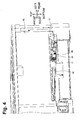
- An image forming apparatus 1 includes an image forming unit 2, a paper feed device 10, and a retransporting unit (a DX unit) 20 as shown in Fig. 1 .
- the image forming unit 2 is an image forming unit configured to form (print) an image on a paper or an OHP sheet (hereinafter, referred to as "paper")
- the paper feed device 10 is a paper feeding unit configured to feed the paper to the image forming unit 2
- the retransporting unit 20 is a retransporting unit for retransporting the paper discharged from the image forming unit 2 toward an inlet port of the image forming unit 2.
- the image forming unit 2 is configured with an electrophotographic-type image forming unit including a process cartridge 3, an exposing unit 4 and a fixing unit 5.
- a process cartridge 3 Stored in the process cartridge 3 are a photosensitive drum 3A configured to carry a developer image, and a charger 3B configured to charge the photosensitive drum 3A.
- the paper transported from the paper feed device 10 toward the image forming unit 2 is transported to a pair of registration rollers 6 and is transported to the photosensitive drum 3A after having corrected in skew by the pair of registration rollers 6.
- the charged photosensitive drum 3A is exposed by the exposing unit 4.
- the developer (powdered toner in the embodiment) is supplied to the photosensitive drum 3A, so that the developer image is carried (formed) on the outer peripheral surface of the photosensitive drum 3A.
- An electric charge having an opposite polarity from that of the developer is applied to a transfer roller 8 disposed on the opposite side of the photosensitive drum 3A with respect to the transported paper, and the developer image carried on the photosensitive drum 3A is transferred to the paper by the transfer roller 8.
- the fixing unit 5 fixes the developer transferred to the paper to the paper by heating the paper after having transferred the developer image.
- the paper discharged from the fixing unit 5 and having formed with the image is redirected upward in the direction of transport while being transported on a transporting path L1 and then is discharged onto a paper discharge tray 9 provided on the side of an upper end surface of the image forming apparatus 1.
- a discharge roller 9A is configured to apply a transporting force to the paper by rotating in a state of being in contact with the paper discarded from the fixing unit 5.
- the discharge roller 9A switches back the paper having completed image formation on the surface thereof and transports the paper toward a retransporting path L2 at the time of duplex printing which forms images on both the front and back surfaces of the paper.
- a pinch roller 9B is configured to press the paper against the discharge roller 9A and pinch the paper in cooperation with the discharge roller 9A.
- the paper feed device 10 includes a paper feed tray 11 on which the papers to be transported to the image forming unit 2 are placed in a stacked manner, a pickup roller 12 configured to come into contact with the paper at the topmost position in the stacking direction from among the papers placed on the paper feed tray 11 and feed the topmost paper toward the image forming unit 2, and a separating mechanism 13 including a separating pad 13A and a separating roller 13B.
- the separating mechanism 13 is a mechanism which separates the plurality of discharged papers and feeds the separated paper to the image forming unit 2 one by one by applying a transporting resistance by the separating pad 13A which comes into contact with the paper on one side from among the plurality of papers fed by the pickup roller 12 and simultaneously applying the transporting force by the separating roller 13B which comes into contact with the paper on the other side.
- a rear cover 1B is an opening and closing unit configured to open part of the transporting path L1 and the retransporting unit 20 is inserted and mounted in an apparatus body 1 A from a mounting port 1C provided between the rear cover 1B and the paper feed tray 11.
- the retransporting unit 20 includes the retransporting path L2 for retransporting the paper discharged from the image forming unit 2 toward the inlet port of the image forming unit 2 (the registration rollers 6) as described above.
- the retransporting path L2 is a transporting path for retransporting the paper having completed the image formation on the surface thereof toward the inlet port of the image forming unit 2 when performing the duplex printing.
- the retransporting unit 20 is detachably inserted and mounted in the apparatus body 1A from the mounting port 1C as shown in Fig. 2 .
- the mounting direction (for example an inserting direction) and demounting direction (for example a drawing direction) of the retransporting unit 20 matches the direction of transport of the paper transported in there transporting path L2 (the retransporting unit 20) (the fore-and-aft direction in the embodiment).
- the apparatus body 1A includes a housing or frame in which the image forming unit 2 is stored.
- the direction of insertion and mounting of the retransporting unit 20 in the apparatus body 1A (the forward direction in the embodiment) is referred to as the direction of insertion.
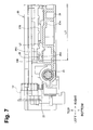
- the retransporting unit 20 includes a transporting roller 21 configured to apply the transporting force on the paper transported through the retransporting path L2 (on the retransporting unit 20), an input gear 22 (an example of an input portion) configured to engage a drive gear 1D (an example of a drive mechanism) (shown in Fig. 4 ) provided on the apparatus body 1A, and a first drive shaft 23 configured to transmit a drive force supplied from the apparatus body 1A via the input gear 22 toward the transporting roller 21.
- a pinch roller 21B Disposed in the apparatus body 1A at a position opposing the transporting roller 21 is a pinch roller 21B (shown in Fig. 1 ) configured to press the paper against the transporting roller 21.
- the input gear 22 is illustrated for easy understanding a relationship between the drive gear 1D and the input gear 22. However, since the input gear 22 is provided in the retransporting unit 20, the input gear 22 is not actually present in a state shown in Fig. 4 (a state in which the retransporting unit 20 is removed).
- a unit body 24 of the retransporting unit 20 is formed with a plurality of projecting ridges 24A extending in a band shape along the direction of paper transport, and the transport of paper is guided by the plurality of projecting ridges 24A.
- the transporting roller 21 is assembled to the forward side in the direction of insertion (the front end side in Fig. 3 ) of the unit body 24 (the retransporting unit 20).
- the input gear 22 is assembled to the unit body 24 at a position shifted in the backward side in the direction of insertion (the rear end side in Fig. 3 ) with respect to the transporting roller 21.
- the input gear 22 is disposed at a position upstream of the transporting roller 21 in a retransporting direction in which the sheet is transported.
- the first drive shaft 23 is formed into a shaft shape extending in the direction parallel to the direction of insertion from the input gear 22 toward the transporting roller 21, and is configured to transmit the drive force from the input gear 22 toward the transporting roller 21 by rotating about an axis.
- transmission of the drive force from the input gear 22 to the first drive shaft 23 and the transmission of the drive force from the first drive shaft 23 to a drive shaft 21A of the transporting roller 21 are achieved via bevel gears 25A to 25D as shown in Fig. 5 .
- the bevel gear 25A is integrated with the input gear 22 (shown in Fig. 6 ), and the bevel gears 25B and 25C are integrated with shaft ends of the first drive shaft 23, respectively, and the bevel gear 25D are integrated to a shaft end of the drive shaft 21A.
- the drive force is supplied from the drive gear 1D in a state in which the drive gear 1D and the input gear 22 are engaged, the drive force is transmitted to the first drive shaft 23 via the bevel gears 25A and 25B, and the drive force transmitted to the first drive shaft 23 is transmitted to the drive shaft 2 1 A via the bevel gears 25C and 25D, so that the transporting roller 21 is rotated.
- the transporting roller 21 is disposed at a substantially center portion in the width direction in an area which constitutes the retransporting path L2.
- the input gear 22 and the first drive shaft 23 are disposed at positions shifted in the width direction from the area which constitutes the retransporting path L2.
- the width direction corresponds to the direction orthogonal to the direction of transport and the thickness direction of the paper, and matches the lateral direction in the embodiment.
- an oblique feed guide 26 extending in the direction of paper transport is assembled to the unit body 24 on one end side of the retransporting path L2 in the width direction so as to extend across a second drive shaft 28 which transmits the drive force to a drive-side oblique feed roller 27A, and the oblique feed guide 26 is formed to have an angular C-shape opened on the side of the retransporting path L2 in cross section orthogonal to the direction of transport as shown in Fig. 7 .
- the oblique feed guide 26 includes a lower side guide surface 26A (an example of a first guide) facing the lower surface side of the paper transported through the retransporting path L2, a side edge guide surface 26B (an example of a second guide) provided at an end portion of the retransporting path L2 in the width direction so as to extend along the direction of paper transport, and an upper side guide surface 26C (an example of a third guide) facing the upper surface side of the paper transported through the retransporting path L2.
- a lower side guide surface 26A an example of a first guide
- a side edge guide surface 26B an example of a second guide
- an upper side guide surface 26C an example of a third guide
- the position of the end portion of the retransporting path L2 in the width direction is determined by the side edge guide surface 26B, and the first drive shaft 23 is disposed on the opposite side of the retransporting path L2 with respect to the side edge guide surface 26B.
- the drive-side oblique feed roller 27A is arranged on the upstream side of the transporting roller 21 in the direction of paper transport, and a driven-side oblique feed roller 27B is disposed at a position opposing the drive-side oblique feed roller 27A. Then, the transporting force to press one end portion of the paper in the width direction, which is transported by the cooperation of the drive-side oblique feed roller 27A and the driven-side oblique feed roller 27B, against the side edge guide surface 26B is applied to the paper.
- the transported paper moves toward the downstream side in the direction of transport while keeping the one end portion thereof in the width direction in contact with the side edge guide surface 26B. Therefore, if the paper is skewed with respect to the direction of transport, the skew is corrected.
- a centerline of the rotating shaft of the driven-side oblique feed roller 27B is inclined with respect to the width direction as shown in Fig. 3 , and a shaft end is pressed toward the drive-side oblique feed roller 27A by a resilient member such as a spring 27C. Therefore, the driven-side oblique feed roller 27B presses the paper against the drive-side oblique feed roller 27A while being rotated in conjunction with the movement of the paper.
- the apparatus body 1A is provided with guide rails 1E (an example of a guide unit) which come into contact with both end sides of the retransporting unit 20 in the width direction to guide the movement of the retransporting unit 20 when the retransporting unit 20 is inserted as shown in Fig. 4 .
- the guide rails 1E are set on the forward side of the drive gear 1D in the direction of insertion of the retransporting unit 20 (the front side of the apparatus body 1A).
- a pair of the guide rails 1E are configured to guide the movement of the retransporting unit 20 so as to hold end portions of the retransporting unit 20 in the width direction from above and below and are configured to have an angular C-shaped cross section in the direction orthogonal to the longitudinal direction thereof.
- the input gear 22 is positioned on the opposite side from the retransporting path L2 with respect to the first drive shaft 23 as shown in Fig. 7 .
- Fig. 7 is a drawing showing a cross section (the cross section taken along the line A-A in Fig. 3 ) orthogonal to the first drive shaft 23. Therefore, the state shown in Fig. 7 is a drawing showing a state in which the retransporting path L2, the input gear 22, and the first drive shaft 23 are projected on an imaginary plane orthogonal to the direction of insertion.
- the retransporting unit 20 When the retransporting unit 20 is viewed in the direction parallel to the direction of the thickness of the paper transported on the retransporting unit 20 (the vertical direction in the embodiment), the retransporting unit 20 has a shape such that an outer edge portion 1F of the retransporting unit 20 corresponding to the input gear 22 projects outward of the an outer edge portion 1G of the retransporting unit 20 corresponding to the first drive shaft 23 as shown in Fig 6 .
- the shape of the retransporting unit 20 on the side of the first drive shaft 23 has a shouldered shape (a stepped shape) as if the outer edge portion 1G corresponding to the first drive shaft 23 is notched.
- the term "outside of the retransporting unit 20" means the side shifted from the retransporting unit 20 toward the apparatus body 1A in the width direction, and is the left side of the retransporting unit 20 in Fig. 6 .
- an engaging pressure Fo acts on the input gear 22.
- the positions and the directions of rotation of the input gear 22 and the drive gear 1D are set so as to cause a component force F1 in the direction toward the forward side in the direction of insertion to be generated in the engaging pressure Fo.
- the drive force is transmitted to the transporting roller 21 by the first drive shaft 23. Therefore, the height of the component portion required for transmitting the drive force is the diametric dimension of the first drive shaft 23, and the diametric dimension becomes sufficiently smaller than the case where the drive force is transmitted with the belt if the drive force to be transmitted is the same. Therefore, in the embodiment, the thickness of the retransporting unit 20 is reduced in comparison with the retransporting unit having configured to transmit the drive fore to the transporting roller 21 with the belt.
- the contact portions between the retransporting unit 20 and the guide rails 1E increase as the insertion of the retransporting unit 20 proceeds, and hence the retransporting unit 20 is stabilized more.
- the contact portions between the retransporting unit 20 and the guide rails 1E are small, and hence the retransporting unit 20 is liable to be unstable.
- the input gear 22 is provided on the retransporting unit 20 at a position shifted on the forward side in the direction of insertion of the retransporting unit 20 with respect to the transporting roller 21, the input gear 22 enters into the apparatus body 1A in the initial state of insertion in which the retransporting unit 20 is still in the unstable state. Therefore, the input gear 22 collides with the apparatus body 1A, and hence the input gear 22 or the apparatus body 1A may become damaged.
- the input gear 22 is provided on the retransporting unit 20 at a position shifted on the backward side in the direction of insertion of the retransporting unit 20 with respect to the transporting roller 21, when the insertion of the retransporting unit 20 is proceeded to an extent in which the input gear 22 enters into the apparatus body 1A, the retransporting unit 20 is stabilized, and hence there is little probability of collision between the input gear 22 and the apparatus body 1A.
- the thickness of the retransporting unit 20 is reduced while restraining the possibility that the input gear 22 or the apparatus body 1A becomes damaged when the retransporting unit 20 is mounted in the apparatus body 1A, so that the downsizing of the image forming apparatus is achieved.
- the first drive shaft 23 is provided on the retransporting unit 20 at a portion corresponding to the area which constitutes the retransporting path L2, it is necessary to arrange the first drive shaft 23 at a position shifted from the retransporting path L2 in the vertical direction so as to avoid the interference between the first drive shaft 23 and the paper transported through the retransporting path L2. Therefore, further reduction of the thickness of the retransporting unit 20 becomes difficult.
- the embodiment is characterized in that the first drive shaft 23 is disposed on the retransporting unit 20 at a position shifted from the area which constitutes the retransporting path L2. Therefore, the thickness of the retransporting unit 20 is further downsized.
- the embodiment is also characterized in that when the retransporting path L2, the input gear 22, and the first drive shaft 23 are projected on the imaginary plane orthogonal to the direction of insertion as shown in Fig. 7 , the projected input gear 22 is positioned on the opposite side from the projected retransporting path L2 with respect to the projected first drive shaft 23.
- the drive gear 1D when inserting and mounting the retransporting unit 20 in the apparatus body 1A, the drive gear 1D is displaced on the backward side in the direction of insertion toward the input gear 22 relatively with the retransporting unit 20 as shown in Fig. 6 .
- the projected input gear 22 is positioned on the opposite side from the projected retransporting path L2 with respect to the projected first drive shaft 23 as shown in Fig. 7 , the interference between the drive gear 1D and the first drive shaft 23 is prevented when the drive gear 1D is displaced relatively with the retransporting unit 20.
- the embodiment is characterized in that when the retransporting unit 20 is viewed in the direction parallel to the direction of the thickness of the paper transported on the retransporting unit 20, the outer edge portion 1F of the retransporting unit 20 corresponding to the input gear 22 projects outward of the outer edge portion 1G of the retransporting unit 20 corresponding to the first drive shaft 23.
- At least part of the drive gear 1D can be displaced relatively with the outside of the outer edge portion of the retransporting unit 20 when the drive gear 1D is displaced relatively with the retransporting unit 20. Therefore, interference between the drive gear 1D and the retransporting unit 20 can be prevented.
- the embodiment is characterized in that the force F1 directed toward the forward side in the direction of insertion acts on the retransporting unit 20 via the input gear 22 as shown in Fig. 8 when the drive force is supplied from the apparatus body 1A to the input gear 22.
- the invention is applied to a monochrome-type image forming apparatus.
- the invention is not limited thereto, and may be applied to a color-type image forming apparatus.
- transmission of the drive force from the input gear 22 to the first drive shaft 23 and transmission of the drive force from the first drive shaft 23 to the drive shaft 21 A of the transporting roller 21 are achieved via the bevel gears 25A to 25D.
- the invention is not limited thereto and, for example, a crown gear, a face gear, or universal joints may be used.
- the shape of the retransporting unit 20 on the side of the first drive shaft 23 has the shouldered shape (the stepped shape) as if the outer edge portion 1G corresponding to the first drive shaft 23 is notched.
- the invention is not limited thereto.
- the retransporting unit 20 is insertable in the retransporting direction.
- the invention is not limited thereto and, for example, retransporting unit 20 may be insertable in a direction orthogonal to the retransporting direction alternatively.
Landscapes
- Physics & Mathematics (AREA)
- General Physics & Mathematics (AREA)
- Delivering By Means Of Belts And Rollers (AREA)
- Handling Of Cut Paper (AREA)
- Conveyance By Endless Belt Conveyors (AREA)
- Sheets, Magazines, And Separation Thereof (AREA)
Applications Claiming Priority (1)
| Application Number | Priority Date | Filing Date | Title |
|---|---|---|---|
| JP2010066693A JP5029720B2 (ja) | 2010-03-23 | 2010-03-23 | 画像形成装置 |
Publications (3)
| Publication Number | Publication Date |
|---|---|
| EP2369415A2 true EP2369415A2 (de) | 2011-09-28 |
| EP2369415A3 EP2369415A3 (de) | 2012-08-29 |
| EP2369415B1 EP2369415B1 (de) | 2016-02-17 |
Family
ID=44170556
Family Applications (1)
| Application Number | Title | Priority Date | Filing Date |
|---|---|---|---|
| EP11002313.2A Active EP2369415B1 (de) | 2010-03-23 | 2011-03-21 | Bilderzeugungsvorrichtung |
Country Status (4)
| Country | Link |
|---|---|
| US (1) | US8849175B2 (de) |
| EP (1) | EP2369415B1 (de) |
| JP (1) | JP5029720B2 (de) |
| CN (1) | CN102198899B (de) |
Cited By (1)
| Publication number | Priority date | Publication date | Assignee | Title |
|---|---|---|---|---|
| US9302884B2 (en) | 2013-09-09 | 2016-04-05 | Brother Kogyo Kabushiki Kaisha | Image forming apparatus |
Families Citing this family (6)
| Publication number | Priority date | Publication date | Assignee | Title |
|---|---|---|---|---|
| CN103738062B (zh) * | 2013-12-19 | 2016-02-17 | 浙江工业大学 | 邮资机的送件装置 |
| JP6380008B2 (ja) * | 2014-10-31 | 2018-08-29 | ブラザー工業株式会社 | 画像形成装置 |
| WO2017099739A1 (en) | 2015-12-09 | 2017-06-15 | Hewlett-Packard Development Company, L.P. | Media tray with ramp |
| CN105565020B (zh) * | 2015-12-29 | 2018-04-13 | 珠海奔图电子有限公司 | 一种图像形成装置及其双面打印纸张输送单元 |
| JP6969421B2 (ja) * | 2018-02-13 | 2021-11-24 | ブラザー工業株式会社 | 画像形成装置 |
| JP2023121476A (ja) * | 2022-02-21 | 2023-08-31 | ブラザー工業株式会社 | 画像形成装置 |
Citations (4)
| Publication number | Priority date | Publication date | Assignee | Title |
|---|---|---|---|---|
| JPH11236172A (ja) | 1998-02-23 | 1999-08-31 | Canon Inc | 画像形成装置 |
| JP2001264953A (ja) | 2000-03-16 | 2001-09-28 | Nidec Copal Corp | 感光材料の搬送装置 |
| JP2007022687A (ja) | 2005-07-12 | 2007-02-01 | Brother Ind Ltd | 画像形成装置 |
| JP2009179411A (ja) | 2008-01-29 | 2009-08-13 | Brother Ind Ltd | 画像形成装置及び両面印刷ユニット |
Family Cites Families (11)
| Publication number | Priority date | Publication date | Assignee | Title |
|---|---|---|---|---|
| US5332205A (en) * | 1991-07-05 | 1994-07-26 | Sindo Ricoh Co., Ltd. | Automatic document feeders for copying machines and method for automatically controlling such |
| US5327206A (en) * | 1991-07-17 | 1994-07-05 | Minolta Camera Kabushiki Kaisha | Image forming apparatus including a sheet refeeding unit |
| JPH07267514A (ja) * | 1994-03-31 | 1995-10-17 | Minolta Co Ltd | 再給紙装置 |
| JP4055352B2 (ja) | 2000-11-07 | 2008-03-05 | ブラザー工業株式会社 | 再搬送装置および画像形成装置 |
| JP3719929B2 (ja) * | 2000-11-29 | 2005-11-24 | 株式会社沖データ | 用紙搬送装置 |
| JP2004266744A (ja) * | 2003-03-04 | 2004-09-24 | Brother Ind Ltd | 画像処理装置及び、画像処理方法、記憶媒体 |
| JP3929955B2 (ja) | 2003-09-17 | 2007-06-13 | 京セラミタ株式会社 | 画像形成装置 |
| JP2006062809A (ja) | 2004-08-26 | 2006-03-09 | Canon Inc | 画像形成装置 |
| JP4561724B2 (ja) | 2006-10-13 | 2010-10-13 | ブラザー工業株式会社 | 画像形成装置 |
| US8200141B2 (en) * | 2008-09-10 | 2012-06-12 | Kabushiki Kaisha Toshiba | Conveying unit for image forming apparatus |
| JP4655146B2 (ja) * | 2008-12-22 | 2011-03-23 | ブラザー工業株式会社 | 画像形成装置 |
-
2010
- 2010-03-23 JP JP2010066693A patent/JP5029720B2/ja active Active
-
2011
- 2011-03-21 EP EP11002313.2A patent/EP2369415B1/de active Active
- 2011-03-22 CN CN201110068117.XA patent/CN102198899B/zh active Active
- 2011-03-22 US US13/053,720 patent/US8849175B2/en active Active
Patent Citations (4)
| Publication number | Priority date | Publication date | Assignee | Title |
|---|---|---|---|---|
| JPH11236172A (ja) | 1998-02-23 | 1999-08-31 | Canon Inc | 画像形成装置 |
| JP2001264953A (ja) | 2000-03-16 | 2001-09-28 | Nidec Copal Corp | 感光材料の搬送装置 |
| JP2007022687A (ja) | 2005-07-12 | 2007-02-01 | Brother Ind Ltd | 画像形成装置 |
| JP2009179411A (ja) | 2008-01-29 | 2009-08-13 | Brother Ind Ltd | 画像形成装置及び両面印刷ユニット |
Cited By (1)
| Publication number | Priority date | Publication date | Assignee | Title |
|---|---|---|---|---|
| US9302884B2 (en) | 2013-09-09 | 2016-04-05 | Brother Kogyo Kabushiki Kaisha | Image forming apparatus |
Also Published As
| Publication number | Publication date |
|---|---|
| EP2369415B1 (de) | 2016-02-17 |
| CN102198899A (zh) | 2011-09-28 |
| US20110236096A1 (en) | 2011-09-29 |
| US8849175B2 (en) | 2014-09-30 |
| EP2369415A3 (de) | 2012-08-29 |
| CN102198899B (zh) | 2014-12-03 |
| JP2011195318A (ja) | 2011-10-06 |
| JP5029720B2 (ja) | 2012-09-19 |
Similar Documents
| Publication | Publication Date | Title |
|---|---|---|
| US8849175B2 (en) | Image forming apparatus | |
| JP6335854B2 (ja) | シート給送装置及び画像形成装置 | |
| US9738473B2 (en) | Sheet detecting apparatus, sheet conveying apparatus, and image forming apparatus | |
| US8752825B2 (en) | Image forming apparatus and sheet transporting apparatus with cover and guide member pivotable with respect to apparatus body | |
| US10183822B2 (en) | Sheet feeding unit, sheet feeding apparatus including sheet feeding unit, and image forming apparatus including sheet feeding apparatus | |
| JP2017121988A (ja) | 給紙装置及び画像形成装置 | |
| JP4838683B2 (ja) | シート搬送装置及び画像形成装置 | |
| JP5939717B2 (ja) | シート搬送装置およびそれを備えた画像形成装置 | |
| US20190092594A1 (en) | Sheet conveying apparatus and image forming apparatus | |
| JP3904041B2 (ja) | 電子写真装置 | |
| US10087026B2 (en) | Sheet conveying apparatus and image forming apparatus including the same | |
| US11334015B2 (en) | Sheet conveyance apparatus and image forming apparatus | |
| US10048643B2 (en) | Image forming apparatus including cover unit provided on apparatus main body in a turnable manner | |
| US20150091242A1 (en) | Image Forming Apparatus | |
| JP6929132B2 (ja) | シート搬送装置及び画像形成装置 | |
| JP7207850B2 (ja) | シート給送装置及び画像形成装置 | |
| CN112748650A (zh) | 片材输送装置及图像形成装置 | |
| JP2020073406A (ja) | 画像形成装置 | |
| US12025946B2 (en) | Image forming apparatus having duplex driven roller unit | |
| JP6598526B2 (ja) | 画像形成装置 | |
| JP6958167B2 (ja) | 画像形成装置 | |
| JP4239889B2 (ja) | 用紙後処理装置 | |
| JP2017048013A (ja) | シート給送装置およびこれを備える画像形成装置 | |
| JP2008230799A (ja) | シート排出機構及びそれを備えた画像形成装置 | |
| JP2021104892A (ja) | 画像形成装置 |
Legal Events
| Date | Code | Title | Description |
|---|---|---|---|
| PUAI | Public reference made under article 153(3) epc to a published international application that has entered the european phase |
Free format text: ORIGINAL CODE: 0009012 |
|
| AK | Designated contracting states |
Kind code of ref document: A2 Designated state(s): AL AT BE BG CH CY CZ DE DK EE ES FI FR GB GR HR HU IE IS IT LI LT LU LV MC MK MT NL NO PL PT RO RS SE SI SK SM TR |
|
| AX | Request for extension of the european patent |
Extension state: BA ME |
|
| PUAL | Search report despatched |
Free format text: ORIGINAL CODE: 0009013 |
|
| AK | Designated contracting states |
Kind code of ref document: A3 Designated state(s): AL AT BE BG CH CY CZ DE DK EE ES FI FR GB GR HR HU IE IS IT LI LT LU LV MC MK MT NL NO PL PT RO RS SE SI SK SM TR |
|
| AX | Request for extension of the european patent |
Extension state: BA ME |
|
| RIC1 | Information provided on ipc code assigned before grant |
Ipc: G03G 15/23 20060101ALI20120726BHEP Ipc: G03G 15/00 20060101AFI20120726BHEP |
|
| 17P | Request for examination filed |
Effective date: 20130228 |
|
| GRAP | Despatch of communication of intention to grant a patent |
Free format text: ORIGINAL CODE: EPIDOSNIGR1 |
|
| INTG | Intention to grant announced |
Effective date: 20150728 |
|
| GRAS | Grant fee paid |
Free format text: ORIGINAL CODE: EPIDOSNIGR3 |
|
| GRAA | (expected) grant |
Free format text: ORIGINAL CODE: 0009210 |
|
| AK | Designated contracting states |
Kind code of ref document: B1 Designated state(s): AL AT BE BG CH CY CZ DE DK EE ES FI FR GB GR HR HU IE IS IT LI LT LU LV MC MK MT NL NO PL PT RO RS SE SI SK SM TR |
|
| REG | Reference to a national code |
Ref country code: GB Ref legal event code: FG4D |
|
| REG | Reference to a national code |
Ref country code: CH Ref legal event code: EP |
|
| REG | Reference to a national code |
Ref country code: IE Ref legal event code: FG4D |
|
| REG | Reference to a national code |
Ref country code: AT Ref legal event code: REF Ref document number: 775926 Country of ref document: AT Kind code of ref document: T Effective date: 20160315 |
|
| REG | Reference to a national code |
Ref country code: FR Ref legal event code: PLFP Year of fee payment: 6 |
|
| REG | Reference to a national code |
Ref country code: DE Ref legal event code: R096 Ref document number: 602011023326 Country of ref document: DE |
|
| RAP2 | Party data changed (patent owner data changed or rights of a patent transferred) |
Owner name: BROTHER KOGYO KABUSHIKI KAISHA |
|
| REG | Reference to a national code |
Ref country code: NL Ref legal event code: MP Effective date: 20160217 |
|
| REG | Reference to a national code |
Ref country code: LT Ref legal event code: MG4D |
|
| REG | Reference to a national code |
Ref country code: AT Ref legal event code: MK05 Ref document number: 775926 Country of ref document: AT Kind code of ref document: T Effective date: 20160217 |
|
| PG25 | Lapsed in a contracting state [announced via postgrant information from national office to epo] |
Ref country code: HR Free format text: LAPSE BECAUSE OF FAILURE TO SUBMIT A TRANSLATION OF THE DESCRIPTION OR TO PAY THE FEE WITHIN THE PRESCRIBED TIME-LIMIT Effective date: 20160217 Ref country code: FI Free format text: LAPSE BECAUSE OF FAILURE TO SUBMIT A TRANSLATION OF THE DESCRIPTION OR TO PAY THE FEE WITHIN THE PRESCRIBED TIME-LIMIT Effective date: 20160217 Ref country code: IT Free format text: LAPSE BECAUSE OF FAILURE TO SUBMIT A TRANSLATION OF THE DESCRIPTION OR TO PAY THE FEE WITHIN THE PRESCRIBED TIME-LIMIT Effective date: 20160217 Ref country code: ES Free format text: LAPSE BECAUSE OF FAILURE TO SUBMIT A TRANSLATION OF THE DESCRIPTION OR TO PAY THE FEE WITHIN THE PRESCRIBED TIME-LIMIT Effective date: 20160217 Ref country code: GR Free format text: LAPSE BECAUSE OF FAILURE TO SUBMIT A TRANSLATION OF THE DESCRIPTION OR TO PAY THE FEE WITHIN THE PRESCRIBED TIME-LIMIT Effective date: 20160518 Ref country code: NO Free format text: LAPSE BECAUSE OF FAILURE TO SUBMIT A TRANSLATION OF THE DESCRIPTION OR TO PAY THE FEE WITHIN THE PRESCRIBED TIME-LIMIT Effective date: 20160517 |
|
| PG25 | Lapsed in a contracting state [announced via postgrant information from national office to epo] |
Ref country code: RS Free format text: LAPSE BECAUSE OF FAILURE TO SUBMIT A TRANSLATION OF THE DESCRIPTION OR TO PAY THE FEE WITHIN THE PRESCRIBED TIME-LIMIT Effective date: 20160217 Ref country code: LT Free format text: LAPSE BECAUSE OF FAILURE TO SUBMIT A TRANSLATION OF THE DESCRIPTION OR TO PAY THE FEE WITHIN THE PRESCRIBED TIME-LIMIT Effective date: 20160217 Ref country code: AT Free format text: LAPSE BECAUSE OF FAILURE TO SUBMIT A TRANSLATION OF THE DESCRIPTION OR TO PAY THE FEE WITHIN THE PRESCRIBED TIME-LIMIT Effective date: 20160217 Ref country code: LV Free format text: LAPSE BECAUSE OF FAILURE TO SUBMIT A TRANSLATION OF THE DESCRIPTION OR TO PAY THE FEE WITHIN THE PRESCRIBED TIME-LIMIT Effective date: 20160217 Ref country code: NL Free format text: LAPSE BECAUSE OF FAILURE TO SUBMIT A TRANSLATION OF THE DESCRIPTION OR TO PAY THE FEE WITHIN THE PRESCRIBED TIME-LIMIT Effective date: 20160217 Ref country code: SE Free format text: LAPSE BECAUSE OF FAILURE TO SUBMIT A TRANSLATION OF THE DESCRIPTION OR TO PAY THE FEE WITHIN THE PRESCRIBED TIME-LIMIT Effective date: 20160217 Ref country code: PT Free format text: LAPSE BECAUSE OF FAILURE TO SUBMIT A TRANSLATION OF THE DESCRIPTION OR TO PAY THE FEE WITHIN THE PRESCRIBED TIME-LIMIT Effective date: 20160617 Ref country code: PL Free format text: LAPSE BECAUSE OF FAILURE TO SUBMIT A TRANSLATION OF THE DESCRIPTION OR TO PAY THE FEE WITHIN THE PRESCRIBED TIME-LIMIT Effective date: 20160217 Ref country code: BE Free format text: LAPSE BECAUSE OF NON-PAYMENT OF DUE FEES Effective date: 20160331 |
|
| PG25 | Lapsed in a contracting state [announced via postgrant information from national office to epo] |
Ref country code: DK Free format text: LAPSE BECAUSE OF FAILURE TO SUBMIT A TRANSLATION OF THE DESCRIPTION OR TO PAY THE FEE WITHIN THE PRESCRIBED TIME-LIMIT Effective date: 20160217 Ref country code: EE Free format text: LAPSE BECAUSE OF FAILURE TO SUBMIT A TRANSLATION OF THE DESCRIPTION OR TO PAY THE FEE WITHIN THE PRESCRIBED TIME-LIMIT Effective date: 20160217 |
|
| REG | Reference to a national code |
Ref country code: CH Ref legal event code: PL |
|
| REG | Reference to a national code |
Ref country code: DE Ref legal event code: R097 Ref document number: 602011023326 Country of ref document: DE |
|
| PG25 | Lapsed in a contracting state [announced via postgrant information from national office to epo] |
Ref country code: SM Free format text: LAPSE BECAUSE OF FAILURE TO SUBMIT A TRANSLATION OF THE DESCRIPTION OR TO PAY THE FEE WITHIN THE PRESCRIBED TIME-LIMIT Effective date: 20160217 Ref country code: SK Free format text: LAPSE BECAUSE OF FAILURE TO SUBMIT A TRANSLATION OF THE DESCRIPTION OR TO PAY THE FEE WITHIN THE PRESCRIBED TIME-LIMIT Effective date: 20160217 Ref country code: RO Free format text: LAPSE BECAUSE OF FAILURE TO SUBMIT A TRANSLATION OF THE DESCRIPTION OR TO PAY THE FEE WITHIN THE PRESCRIBED TIME-LIMIT Effective date: 20160217 Ref country code: CZ Free format text: LAPSE BECAUSE OF FAILURE TO SUBMIT A TRANSLATION OF THE DESCRIPTION OR TO PAY THE FEE WITHIN THE PRESCRIBED TIME-LIMIT Effective date: 20160217 |
|
| PLBE | No opposition filed within time limit |
Free format text: ORIGINAL CODE: 0009261 |
|
| STAA | Information on the status of an ep patent application or granted ep patent |
Free format text: STATUS: NO OPPOSITION FILED WITHIN TIME LIMIT |
|
| REG | Reference to a national code |
Ref country code: IE Ref legal event code: MM4A |
|
| PG25 | Lapsed in a contracting state [announced via postgrant information from national office to epo] |
Ref country code: BE Free format text: LAPSE BECAUSE OF FAILURE TO SUBMIT A TRANSLATION OF THE DESCRIPTION OR TO PAY THE FEE WITHIN THE PRESCRIBED TIME-LIMIT Effective date: 20160217 |
|
| 26N | No opposition filed |
Effective date: 20161118 |
|
| PG25 | Lapsed in a contracting state [announced via postgrant information from national office to epo] |
Ref country code: CH Free format text: LAPSE BECAUSE OF NON-PAYMENT OF DUE FEES Effective date: 20160331 Ref country code: LI Free format text: LAPSE BECAUSE OF NON-PAYMENT OF DUE FEES Effective date: 20160331 Ref country code: IE Free format text: LAPSE BECAUSE OF NON-PAYMENT OF DUE FEES Effective date: 20160321 |
|
| REG | Reference to a national code |
Ref country code: FR Ref legal event code: PLFP Year of fee payment: 7 |
|
| PG25 | Lapsed in a contracting state [announced via postgrant information from national office to epo] |
Ref country code: BG Free format text: LAPSE BECAUSE OF FAILURE TO SUBMIT A TRANSLATION OF THE DESCRIPTION OR TO PAY THE FEE WITHIN THE PRESCRIBED TIME-LIMIT Effective date: 20160517 Ref country code: SI Free format text: LAPSE BECAUSE OF FAILURE TO SUBMIT A TRANSLATION OF THE DESCRIPTION OR TO PAY THE FEE WITHIN THE PRESCRIBED TIME-LIMIT Effective date: 20160217 |
|
| PG25 | Lapsed in a contracting state [announced via postgrant information from national office to epo] |
Ref country code: MT Free format text: LAPSE BECAUSE OF FAILURE TO SUBMIT A TRANSLATION OF THE DESCRIPTION OR TO PAY THE FEE WITHIN THE PRESCRIBED TIME-LIMIT Effective date: 20160217 |
|
| REG | Reference to a national code |
Ref country code: FR Ref legal event code: PLFP Year of fee payment: 8 |
|
| PG25 | Lapsed in a contracting state [announced via postgrant information from national office to epo] |
Ref country code: HU Free format text: LAPSE BECAUSE OF FAILURE TO SUBMIT A TRANSLATION OF THE DESCRIPTION OR TO PAY THE FEE WITHIN THE PRESCRIBED TIME-LIMIT; INVALID AB INITIO Effective date: 20110321 Ref country code: CY Free format text: LAPSE BECAUSE OF FAILURE TO SUBMIT A TRANSLATION OF THE DESCRIPTION OR TO PAY THE FEE WITHIN THE PRESCRIBED TIME-LIMIT Effective date: 20160217 |
|
| PG25 | Lapsed in a contracting state [announced via postgrant information from national office to epo] |
Ref country code: MT Free format text: LAPSE BECAUSE OF FAILURE TO SUBMIT A TRANSLATION OF THE DESCRIPTION OR TO PAY THE FEE WITHIN THE PRESCRIBED TIME-LIMIT Effective date: 20160331 Ref country code: MC Free format text: LAPSE BECAUSE OF FAILURE TO SUBMIT A TRANSLATION OF THE DESCRIPTION OR TO PAY THE FEE WITHIN THE PRESCRIBED TIME-LIMIT Effective date: 20160217 Ref country code: IS Free format text: LAPSE BECAUSE OF FAILURE TO SUBMIT A TRANSLATION OF THE DESCRIPTION OR TO PAY THE FEE WITHIN THE PRESCRIBED TIME-LIMIT Effective date: 20160217 Ref country code: MK Free format text: LAPSE BECAUSE OF FAILURE TO SUBMIT A TRANSLATION OF THE DESCRIPTION OR TO PAY THE FEE WITHIN THE PRESCRIBED TIME-LIMIT Effective date: 20160217 Ref country code: LU Free format text: LAPSE BECAUSE OF NON-PAYMENT OF DUE FEES Effective date: 20160321 Ref country code: TR Free format text: LAPSE BECAUSE OF FAILURE TO SUBMIT A TRANSLATION OF THE DESCRIPTION OR TO PAY THE FEE WITHIN THE PRESCRIBED TIME-LIMIT Effective date: 20160217 |
|
| PG25 | Lapsed in a contracting state [announced via postgrant information from national office to epo] |
Ref country code: AL Free format text: LAPSE BECAUSE OF FAILURE TO SUBMIT A TRANSLATION OF THE DESCRIPTION OR TO PAY THE FEE WITHIN THE PRESCRIBED TIME-LIMIT Effective date: 20160217 |
|
| P01 | Opt-out of the competence of the unified patent court (upc) registered |
Effective date: 20230529 |
|
| PGFP | Annual fee paid to national office [announced via postgrant information from national office to epo] |
Ref country code: DE Payment date: 20250210 Year of fee payment: 15 |
|
| PGFP | Annual fee paid to national office [announced via postgrant information from national office to epo] |
Ref country code: FR Payment date: 20250210 Year of fee payment: 15 |
|
| PGFP | Annual fee paid to national office [announced via postgrant information from national office to epo] |
Ref country code: GB Payment date: 20250213 Year of fee payment: 15 |