EP2369319B1 - Procédé et dispositif de mesure d'objets asphériques - Google Patents
Procédé et dispositif de mesure d'objets asphériques Download PDFInfo
- Publication number
- EP2369319B1 EP2369319B1 EP11159211.9A EP11159211A EP2369319B1 EP 2369319 B1 EP2369319 B1 EP 2369319B1 EP 11159211 A EP11159211 A EP 11159211A EP 2369319 B1 EP2369319 B1 EP 2369319B1
- Authority
- EP
- European Patent Office
- Prior art keywords
- specimen surface
- optical axis
- measuring optical
- tilt
- shift amount
- Prior art date
- Legal status (The legal status is an assumption and is not a legal conclusion. Google has not performed a legal analysis and makes no representation as to the accuracy of the status listed.)
- Not-in-force
Links
Images


Classifications
-
- G—PHYSICS
- G01—MEASURING; TESTING
- G01M—TESTING STATIC OR DYNAMIC BALANCE OF MACHINES OR STRUCTURES; TESTING OF STRUCTURES OR APPARATUS, NOT OTHERWISE PROVIDED FOR
- G01M11/00—Testing of optical apparatus; Testing structures by optical methods not otherwise provided for
- G01M11/02—Testing optical properties
- G01M11/0242—Testing optical properties by measuring geometrical properties or aberrations
- G01M11/025—Testing optical properties by measuring geometrical properties or aberrations by determining the shape of the object to be tested
-
- G—PHYSICS
- G01—MEASURING; TESTING
- G01M—TESTING STATIC OR DYNAMIC BALANCE OF MACHINES OR STRUCTURES; TESTING OF STRUCTURES OR APPARATUS, NOT OTHERWISE PROVIDED FOR
- G01M11/00—Testing of optical apparatus; Testing structures by optical methods not otherwise provided for
- G01M11/02—Testing optical properties
-
- G—PHYSICS
- G01—MEASURING; TESTING
- G01B—MEASURING LENGTH, THICKNESS OR SIMILAR LINEAR DIMENSIONS; MEASURING ANGLES; MEASURING AREAS; MEASURING IRREGULARITIES OF SURFACES OR CONTOURS
- G01B11/00—Measuring arrangements characterised by the use of optical techniques
- G01B11/24—Measuring arrangements characterised by the use of optical techniques for measuring contours or curvatures
- G01B11/2441—Measuring arrangements characterised by the use of optical techniques for measuring contours or curvatures using interferometry
-
- G—PHYSICS
- G01—MEASURING; TESTING
- G01B—MEASURING LENGTH, THICKNESS OR SIMILAR LINEAR DIMENSIONS; MEASURING ANGLES; MEASURING AREAS; MEASURING IRREGULARITIES OF SURFACES OR CONTOURS
- G01B11/00—Measuring arrangements characterised by the use of optical techniques
- G01B11/26—Measuring arrangements characterised by the use of optical techniques for measuring angles or tapers; for testing the alignment of axes
-
- G—PHYSICS
- G01—MEASURING; TESTING
- G01B—MEASURING LENGTH, THICKNESS OR SIMILAR LINEAR DIMENSIONS; MEASURING ANGLES; MEASURING AREAS; MEASURING IRREGULARITIES OF SURFACES OR CONTOURS
- G01B9/00—Measuring instruments characterised by the use of optical techniques
- G01B9/02—Interferometers
-
- G—PHYSICS
- G01—MEASURING; TESTING
- G01M—TESTING STATIC OR DYNAMIC BALANCE OF MACHINES OR STRUCTURES; TESTING OF STRUCTURES OR APPARATUS, NOT OTHERWISE PROVIDED FOR
- G01M11/00—Testing of optical apparatus; Testing structures by optical methods not otherwise provided for
- G01M11/02—Testing optical properties
- G01M11/0242—Testing optical properties by measuring geometrical properties or aberrations
- G01M11/0271—Testing optical properties by measuring geometrical properties or aberrations by using interferometric methods
-
- G—PHYSICS
- G02—OPTICS
- G02B—OPTICAL ELEMENTS, SYSTEMS OR APPARATUS
- G02B3/00—Simple or compound lenses
- G02B3/02—Simple or compound lenses with non-spherical faces
Definitions
- the present invention relates to a method of and an apparatus for measuring an aspheric obj ect or element, e.g. an aspheric lens or a bi-aspheric mirror, which is used in many kinds of optical devices such as digital cameras and optical sensors, to detect misalignment between front and rear surfaces (first and second specimen surfaces) of the aspheric object.
- an aspheric obj ect or element e.g. an aspheric lens or a bi-aspheric mirror, which is used in many kinds of optical devices such as digital cameras and optical sensors, to detect misalignment between front and rear surfaces (first and second specimen surfaces) of the aspheric object.
- the molded lens may sometimes suffer misalignment between its opposite surfaces from deviation of the relative positions of the molding dies.
- the misalignment may include decentration (deviation of a rotational axis of one surface of the aspheric lens from a rotational axis of the other surface) and tilt (inclination of the rotational axis of one surface to the rotational axis of the other surface). Due to the mechanism of the molding dies, it is impossible to prevent the lens misalignment completely, but it is desirable to design and correct the molding dies so as to reduce the lens misalignment to the minimum because it will increase aberrations, especially rotationally asymmetric aberration, of the molded aspheric lens. For this purpose, it is important to measure the actual amounts of the decentration and tilt of the molded lens accurately.
- a geometry measuring apparatus with contact probes is used to measure the geometry of each of the two lens surfaces, to determine the relative decentration and tilt on the basis of the measured geometries.
- This conventional method has a problem in that it takes more than several hours for the measurement of one lens.
- JPA 2007-033343 A measuring method that can substantially save time has recently been suggested in JPA 2007-033343 , wherein a wave front of transmitted light through an aspheric lens is measured by an interferometer to obtain data of the transmitted wave front, and a coma aberration of the transmitted wave front is calculated based on the obtained data. Then, a relative decentration amount (interplanar decentration amount) and a relative tilt amount (interplanar tilt amount) are derived from the calculated coma aberration. Specifically, the transmitted wave front data is approximated with a Zernike polynomial.
- coefficient Z 6 or Z 7 having a value that varies with the third order coma aberration, and the coefficient Z 13 or Z 14 having a value that varies with the fifth order coma aberration are used as the basis for determining the decentration and tilt.
- the shape or pattern of the wave front of the transmitted light is significantly influenced by the refractive index distribution inside the aspherical lens as well as the decentration and the tilt between the lens surfaces to be inspected. Accordingly, it is difficult for the above prior art method to measure the decentration and the tilt with accuracy on the basis of the data of the transmitted wave front while eliminating the influence of the refractive index distribution of the lens material.
- the above prior art method can hardly work for the misalignment measurement of such an aspheric object that does not transmit measuring beams from the interferometer, e.g. an aspheric lens served for a ray of specific wavelength, such as X-ray, or a bi-aspheric mirror having rotationally symmetric aspheric reflective surfaces.
- an aspheric lens served for a ray of specific wavelength, such as X-ray, or a bi-aspheric mirror having rotationally symmetric aspheric reflective surfaces.
- an object of the present invention is to provide a method and an apparatus for measuring an aspheric object, which allows to measure the decentration amount and the tilt amount between opposite surfaces of the aspheric object without any influence of the refractive index distribution inside the aspheric object, or even while the aspheric object does not transmit measuring beams from interferometers.
- a method of measuring decentration and tilt of a first specimen surface of an aspheric object relative to a second specimen surface of the aspheric object uses first and second interferometers, wherein the relative positions of the first and second interferometers to each other are determined.
- the first specimen surface is a rotationally symmetric aspheric surface
- the second specimen surface may be a rotationally symmetric aspheric surface or a spherical surface.
- the method of the present invention comprises the following steps:
- the above Zernike polynomial is a Zernike polynomial Z( ⁇ , ⁇ ) of the fourth or higher order that is expressed in the form of polar coordinates, wherein ⁇ represents a distance from a pole and ⁇ a tilt angle to an initial line.
- the first shift amount proportionality coefficient and the second shift amount proportionality coefficient are a coefficient Z 1 of a term expressed by a formula ⁇ cos ⁇ and a coefficient Z 2 of a term expressed by a formula ⁇ sin ⁇ .
- the present invention provides an apparatus that measures decentration and tilt of a first specimen surface of an aspheric object relative to a second specimen surface of the aspheric object, wherein the first specimen surface is a rotationally symmetric aspheric surface and the second specimen surface may be a rotationally symmetric aspheric surface or a spherical surface.
- the measuring apparatus of the present invention comprises first and second interferometers.
- the first interferometer projects a first measuring beam onto the first specimen surface along a first measuring optical axis, to capture image data of first interference fringes that are produced by optical interference between a first reflection wave front of the first measuring beam as reflected from the first specimen surface and a first reference wave front of the first interferometer.
- the second interferometer projects a second measuring beam onto the second specimen surface along a second measuring optical axis, to capture image data of second interference fringes that are produced by optical interference between a second reflection wave front of the second measuring beam as reflected from the second specimen surface and a second reference wave front of the second interferometer, wherein the relative position of the second interferometer to the first interferometer is determined.
- the measuring apparatus of the present invention further comprises first and second specimen surface geometric data acquiring devices, first and second Zernike coefficient calculators, first and second apex decentricity calculators, and first and second shift and tilt amount calculators.
- the first and second specimen surface geometric data acquiring devices analyze the image data of the first interference fringes and the image data of the second interference fringes to acquire geometric data of the first and second specimen surfaces respectively.
- the first and second Zernike coefficient calculators approximate the geometric data of the first and second specimen surfaces with Zernike polynomials to calculate, among coefficients of respective terms of the Zernike polynomial, values of a first shift amount proportionality coefficient that is variable in proportion to a shift amount of the first specimen surface in a perpendicular direction to the first measuring optical axis, a value of a first tilt amount proportionality coefficient that is variable in proportion to a tilt amount of the first specimen surface to the first measuring optical axis, a value of a second shift amount proportionality coefficient that is variable in proportion to a shift amount of the second specimen surface in a perpendicular direction to the second measuring optical axis, and a value of a second tilt amount proportionality coefficient that is variable in proportion to a tilt amount of the second specimen surface to the second measuring optical axis.
- the first and second apex decentricity calculators calculate a value of decentricity of an apex of the first specimen surface to the first measuring optical axis and a value of decentricity of an apex of the second specimen surface to the second measuring optical axis on the basis of the geometric data of the first specimen surface and the geometric data of the second specimen surface respectively.
- the first shift and tilt amount calculator calculates a shift amount and a tilt amount of the first specimen surface to the first measuring optical axis on the basis of the values of the first shift amount proportionality coefficient, the first tilt amount proportionality coefficient and the apex decentricity of the first specimen surface.
- the second shift and tilt amount calculator calculates a shift amount and a tilt amount of the second specimen surface to the second measuring optical axis on the basis of the values of the second shift amount proportionality coefficient, the second tilt amount proportionality coefficient and the second apex decentricity of the second specimen surface.
- the measuring apparatus of the present invention further comprises a device for determining amounts of the relative decentration and tilt of the first specimen surface to the second specimen surface on the basis of the calculated shift and tilt amounts of the first specimen surface, the calculated shift and tilt amounts of the second specimen surface, and information on the relative positions of the first and second interferometers.
- the above shift and tilt amount calculation in the method and the apparatus of the present invention should be carried out on the assumption that the tilt amount of the second specimen surface is zero.
- the apex of the first specimen surface is a point in a central area of the first specimen surface, at which the first specimen surface is perpendicular to the first measuring optical axis; the position of the apex in the first specimen surface changes with a change in tilt amount of the first specimen surface to the first measuring optical axis.
- the apex decentricity of the first specimen surface to the first measuring optical axis is a distance from the apex of the first specimen surface to the first measuring optical axis in the perpendicular direction to the first measuring optical axis.
- the apex of the second specimen surface is a point in a central area of the second specimen surface, at which the second specimen surface is perpendicular to the second measuring optical axis; the position of the apex in the second specimen surface changes with a change in tilt amount of the second specimen surface to the second measuring optical axis.
- the apex decentricity of the second specimen surface to the second measuring optical axis is a distance from the apex of the second specimen surface to the second measuring optical axis in the perpendicular direction to the second measuring optical axis.
- the present invention makes it possible to measure the relative decentration and tilt between opposite surfaces of an aspheric object that does not transmit the measuring beams from the interferometers.
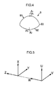
- an aspheric lens 9 as an aspheric object to be measured in the present embodiment will be explained with respect to the composition and terms for measurement.
- the aspheric lens 9 is designed to have a first lens surface 91 (a first specimen surface of the present embodiment), a second lens surface 92 (a second specimen surface of the present embodiment), and a cylindrical side surface 93.
- the first lens surface 91 constitutes a rotationally symmetric aspheric surface about a first rotational axis A1
- the second lens surface 92 constitutes a rotational aspheric surface about a second rotational axis A2.
- the first lens surface 91 intersects with the first rotational axis A1 at a center point P1 of the first lens surface 91, and the center point P1 is designed to be an umbilical point; the normal curvature at the center point P1 is equal in every tangential direction to the first lens surface 91.
- the second lens surface 92 intersects with the second rotational axis A2 at a center point P2 of the second lens surface 92, and the center point P2 is designed to be an umbilical point; the normal curvature at the center point P2 is equal in every tangential direction to the second lens surface 92.
- the axes A1 and A2 are designed to be coincident or in alignment with each other. Because of manufacture errors or the like, however, these axes cannot always be in alignment with each other, which may be called misalignment and include decentration and tilt of these axes A1 and A2 relative to each other.
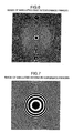
- Fig. 4 shows a case where these axes A1 and A2 are misaligned in an exaggerated manner, although the magnitude of such an error or deviation is normally in the order of wavelength of the light.
- the relative tilt and decentration between the lens surfaces 91 and 92 of the aspheric lens 9 shall be defined as follows.
- Decentration When the center point P1 of the first lens surface 91 (the intersection between the first lens surface 91 and the first rotational axis A1) and the center point P2 of the second lens surface 92 (the intersection between the second lens surface 92 and the second rotational axis A2) are projected onto a virtual plane that is vertical to the rotational axis A1 or A2, a distance between the projected points of the center points P1 and P2 on the virtual plane shall be defined as the amount of decentration.
- An orthogonal coordinate system may be defined in the virtual plane so as to decompose the decentration into components in the directions of the coordinate axes.
- Tilt An angle formed by the axes A1 and A2 (or an angle formed by direction vectors of the axes A1 and A2 when these axes do not intersect with each other) shall be defined as the amount of tilt.
- An orthogonal coordinate system may be defined in a virtual plane so as to decompose the tilt into components in the directions of the coordinate axes.
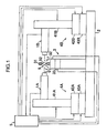
- FIG.1 A structure of an aspheric object measuring apparatus in accordance with an embodiment of the present invention will now be described with reference to Figs. 1 to 3 .
- the aspheric object measuring apparatus shown in Fig.1 is provided to measure and analyze the decentration and tilt of the above mentioned aspheric lens 9.
- the aspheric object measuring apparatus includes a first interferometer 1A disposed on the side of the first lens surface 91 of the aspheric lens 9, a second interferometer 1B disposed on the side of the second lens surface 92, a test object alignment section 3 for aligning a test object for inspection, a first positioning section 4A for positioning the first interferometer 1A, a second positioning section 4B for positioning the second interferometer 1B, and a controller analyzer 5 that executes measurement and analysis of the decentration and the tilt of the aspheric lens 9 and other processes.
- the obj ect alignment section 3 and the first and second interferometer positioning sections 4A and 4B are mounted on an optical board 2.
- the first interferometer 1A includes a first interference optical system 10A, a first interference fringe imaging system 20A and a first alignment imaging system 25A.
- the first interference optical system 10A constitutes a Fizeau type optical arrangement, which includes a light source 11A for outputting a highly coherent beam, a beam expanding lens 12A for expanding the beam diameter of the light from the light source 11A, a beam splitter 13A for reflecting the beam from the beam expanding lens 12A to the right hand side in the drawing, a collimator lens 14A for collimating the beam from the beam splitter 13A, a flat standard plate 15A, and an objective lens 18A.
- a fragment of plane waves from the collimator lens 14A is reflected backward from a reference standard flat surface or reference plane 15Aa of the flat standard plate 15A, to be a first reference beam.
- the remaining plane waves are let pass through the flat standard plate 15A along a first measuring optical axis L1.
- the objective lens 18A converts the plane waves from the flat standard plate 15A to a first measuring beam that is composed of spherical waves, and projects the first measuring beam onto a center area of the first lens surface 91, i.e. an area including the above-mentioned first center point P1.
- the light reflected from the first lens surface 91 merges with the first reference beam to get a first interfering light.
- the flat standard plate 15A is held by a fringe scan adaptor 17A that is provided with a piezo element 16A such that the flat standard plate 15A is subtly movable in the direction of the first measuring optical axis L1 during the execution of fringe scanning measurement or the like.
- the objective lens 18A is configured to be retractable from the first measuring optical axis L1.
- the first interference fringe imaging system 20A serves for the measurement of the aspheric lens 9 (the first lens surface 91), and includes an imaging lens 22A and a camera 23A having a 2D or planer image sensor 24A such as CCD or CMOS image sensor.
- the imaging lens 22A converges the first interfering light traveling leftward in the drawing through the beam splitter 13A and a beam splitter 21A, to form interference fringes (first interference fringes) on the 2D image sensor 24A, thereby to capture image data of the interference fringes.
- the alignment imaging system 25A serves for alignment of relative positions of the first and second interferometers 1A and 1B to each other.
- the alignment imaging system 25A includes an imaging lens 26A for converging a beam reflected downward from the beam splitter 21A in the drawing, and a camera 27A having a 2D image sensor 28A such as CCD or CMOS image sensor.
- the second interferometer 1B has the same structure as the first interferometer 1A, including the second interference optical system 10B, a second interference fringe imaging system 20B and a second alignment imaging system 25B.
- the second interference optical system 10B has a Fizeau type optical arrangement, which includes a light source 11B for outputting a highly coherent beam, a beam expanding lens 12B for expanding the beam diameter of the light from the light source 11B, a beam splitter 13B for reflecting the beam from the beam expanding lens 12B to the right hand side in the drawing, a collimator lens 14B for collimating the beam from the beam splitter 13B, a flat standard plate 15B, and an objective lens 18B.
- Plane waves from the collimator lens 14B are partly reflected backward at a reference standard flat surface 15Ba of the referential flat plate 15B, to be a second reference beam.
- the remaining plane waves are let pass through the flat standard plate 15B along a second measuring optical axis L2.
- the objective lens 18B converts the plane waves from the flat standard plate 15B to a second measuring beam that is composed of spherical waves, and projects the second measuring beam onto a center area of the first lens surface 91, i.e. an area including the above-mentioned second center point P2.
- the beam reflected from the first lens surface 91 merges with the second reference beam to get a second interfering light.
- the flat standard plate 15B is held by a fringe scan adaptor 17B that is provided with a piezo element 16B such that the flat standard plate 15B is subtly movable in the direction of the second measuring optical axis L2 during the execution of fringe scanning measurement or the like.
- the objective lens 18B is configured to be retractable from the second measuring optical axis L2.
- the second interference fringe imaging system 20B serves for the measurement of the aspheric lens 9 (the second lens surface 92), and includes an imaging lens 22B and a camera 23B having a 2D or planer image sensor 24B such as CCD or CMOS image sensor.
- the imaging lens 22B converges the second interfering light traveling rightward in the drawing through the beam splitter 13B and a beam splitter 21B, to form interference fringes (second interference fringes) on the 2D image sensor 24B, thereby to capture image data of the interference fringes.
- the alignment imaging system 25B serves for alignment of relative positions of the first and second interferometers 1A and 1B.
- the alignment imaging system 25B includes an imaging lens 26B for converging a beam reflected downward from the beam splitter 21B in the drawing, and a camera 27B having a 2D image sensor 28B such as CCD or CMOS image sensor.
- the test object alignment section 3 includes a holder stage 31 for holding the aspheric lens 9, a lens inclination adjusting stage 32 for adjusting the inclination of the aspheric lens 9 as being held on the holder stage 31 relative to the first and second measuring optical axes L1 and L2, and a lens position adjusting stage 33 for adjusting the position of the aspheric lens 9 relative to the first and second measuring optical axes L1 and L2 in the right and left directions in the drawing as well as in the perpendicular direction to the plane of the drawing.
- the first interferometer positioning section 4A includes a first Z stage 41A for holding the first interferometer 1A movable in a vertical direction Z, a first XY stage 42A for holding the first interferometer 1A movable in the right and left directions in the drawing as well as in the perpendicular direction to the plane of the drawing, and a first interferometer inclination adjusting stage 43A that adjusts the inclination of the first interferometer 1A through the first XY stage 42A and the first Z stage 41A.
- the second interferometer positioning section 4B includes a second Z stage 41B for holding the second interferometer 1B movable in a vertical direction Z, a second XY stage 42B for holding the second interferometer 1B movable in the right and left directions in the drawing as well as in the perpendicular direction to the plane of the drawing, and a second interferometer inclination adjusting stage 43B that adjusts the inclination of the second interferometer 1B through the second XY stage 42B and the second Z stage 41B.
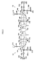
- the controller analyzer 5 is constituted of a computer and the like, which can acquire geometric data about the respective central areas of the first and second lens surfaces 91 and 92 (first specimen surface geometric data and second specimen surface geometric data), and control driving the respective stages of the test object alignment section 3, the first and second interferometer positioning sections 4A and 4B. As shown in Fig.
- the controller analyzer 5 includes a first specimen surface geometric data acquiring device 51A, a second specimen surface geometric data acquiring device 51B, a first Zernike coefficient calculator 52A, a second Zernike coefficient calculator 52B, a first apex decentricity calculator 53A, a second apex decentricity calculator 53B, a first shift and tilt amount calculator 54A, a second shift and tilt amount calculator 54B, and a misalignment calculator 55.
- the first specimen surface geometric data acquiring device 51A acquires first specimen surface geometric data from the image data of the first interference fringes, representing geometric data of the central area of the first lens surface 91 in a first coordinate system for measurement that is defined in the first interferometer 1A.
- the second specimen surface geometric data acquiring device 51B acquires second specimen surface geometric data from the image data of the second interference fringes, representing geometric data of the central area of the second lens surface 92 in a second coordinate system for measurement that is defined in the second interferometer 1B.
- the first Zernike coefficient calculator 52A approximates the first specimen surface geometric data with a Zernike polynomial, to calculate, among coefficients of the respective terms of the Zernike polynomial, the value of a first shift amount proportionality coefficient that is variable in proportion to the shift amount of the first lens surface 91 in a perpendicular direction to the first measuring optical axis L1, and the value of a first tilt amount proportionality coefficient that is variable in proportion to the tilt amount of the first lens surface 91 with respect to the first measuring optical axis L1.
- the second Zernike coefficient calculator 52B approximates the second specimen surface geometric data with a Zernike polynomial, to calculate, among coefficients of the respective terms of the Zernike polynomial, the value of a second shift amount proportionality coefficient that is variable in proportion to the shift amount of the second lens surface 92 in a perpendicular direction to the second measuring optical axis L2, and the value of a second tilt amount proportionality coefficient that is variable in proportion to the tilt amount of the second lens surface 92 with respect to the second measuring optical axis L2.
- the first apex decentricity calculator 53A calculates the value of decentricity of the apex of the first lens surface 91 relative to the first measuring optical axis L1 on the basis of the geometric data of the first lens surface 91 acquired by the first specimen surface geometric data acquiring device 51A.
- the value calculated by the first apex decentricity calculator 53A which may also be referred to as the first apex decentricity hereinafter, is variable in proportion to the shift amount of the first lens surface 91 in the perpendicular direction to the first measuring optical axis L1 and the tilt amount of the first lens surface 91 to the first measuring optical axis L1.
- the second apex decentricity calculator 53B calculates the value of decentricity of the apex of the second lens surface 92 relative to the second measuring optical axis L2 on the basis of the geometric data of the second lens surface 92 acquired by the second specimen surface geometric data acquiring device 51B.
- the value calculated by the second apex decentricity calculator 53B which may also be referred to as the second apex decentricity hereinafter, is variable in proportion to the shift amount of the second lens surface 92 in the perpendicular direction to the second measuring optical axis L2 and the tilt amount of the second lens surface 92 to the second measuring optical axis L2.
- the first shift and tilt amount calculator 54A calculates a shift amount and a tilt amount of the first lens surface 91 to the first measuring beams axis L1 on the basis of the first shift amount proportionality coefficient and the first tilt amount proportionality coefficient, having the values calculated by the first Zernike coefficient calculator 52A, and the value of the first apex decentricity calculated by the first apex decentricity calculator 53A.
- the second shift and tilt amount calculator 54B calculates a shift amount and a tilt amount of the second lens surface 92 to the second measuring beams axis L2 on the basis of the second shift amount proportionality coefficient and the second tilt amount proportionality coefficient, having the values calculated by the second Zernike coefficient calculator 52B, and the value of the second apex decentricity calculated by the second apex decentricity calculator 53B.
- the misalignment calculator 55 calculates the amount of the decentration and the amount of the lens tilt on the basis of the shift amount and the tilt amount of the first lens surface 91 as calculated by the first shift and tilt amount calculator 54A, and the shift amount and the tilt amount of the second lens surface 92 as calculated by the second shift and tilt amount calculator 54B, while taking account of the relative position between the first and second interferometers 1A and 1B (the positional relationship between the first and second coordinate systems for measurement).
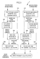
- the aspheric object measuring method according to the present embodiment uses the above aspheric object measuring apparatus.
- a simulated first lens surface corresponding to the first lens surface 91 and a simulated second lens surface corresponding to the second lens surface 92 are provided on a computer on the basis of design data of the first and second lens surfaces 91 and 92.
- images of simulated first and second interference fringes are produced corresponding to the above images of the first and second interference fringes respectively, which will be obtained when the simulated first and second lens surfaces are subjected to the optical interference measurement using the first and second interferometers 1A and 1B.
- an appropriate masking device is set to limit the range of the interference fringes to be served for the analysis.
- the simulated first and second interference fringe images are produced at each tilt amount.
- the simulated first and second interference fringe images detected at each grade of tilt amount are analyzed to obtain geometric data of the simulated first and second lens surfaces at each tilt grade.
- the respective values of the coefficients Z 1 and Z 2 of the Zernike polynomial approximating the obtained geometric data are determined, and the respective values of the apex decentricity of the simulated first and second lens surfaces are determined.
- the simulated first lens surface should be tilted pivotally about its center point (an intersection of the simulated first lens surface with its rotational axis).
- the simulated second lens surface should be tilted pivotally about its center point (an intersection of the simulated second lens surface with its rotational axis).
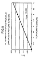
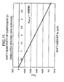
- Fig.8 shows a relationship between the tilt amount t x of the simulated first lens surface (x implies that the tilt amount is in the direction of the X axis of the first coordinate system for measurement) and the value Z 1(1-t) of the coefficient Z 1 at the tilt amount t x (the value Z 1(1-t) being amended to be zero when the tilt amount t x is zero).
- a 1(1-t) was determined to be 0.059:
- Z 1 ⁇ 1 - t a 1 ⁇ 1 - t • - t x
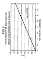
- Fig.9 a relationship between the tilt amount t u of the simulated second lens surface (u implies that the tilt amount is in the direction of the U axis of the second coordinate system for measurement) and the value Z 1(2-t) of the coefficient Z 1 at the tilt amount t u (the value Z 1(2-t) being amended to be zero when the tilt amount t u is zero).
- a 1(2-t) was determined to be 0.0721:
- Z 1 ⁇ 2 - t a 1 ⁇ 2 - t • t u
- the simulated first and second interference fringe images are produced at each shift amount (the shift amount being set to be zero).
- the simulated first and second interference fringe images detected at each grade of shift amount are analyzed to obtain geometric data of the simulated first and second lens surfaces at each shift grade. Then, the respective values of the coefficients Z 1 and Z 2 of the Zernike polynomial approximating the obtained geometric data are determined.
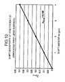
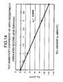
- Fig. 10 shows a relationship between the shift amount s x of the simulated first lens surface (x implies that the shift amount is in the direction of the X axis of the first coordinate system for measurement) and the value Z 1(1-s) of the coefficient Z 1 at the shift amount s x (the value Z 1(1-s) being amended to be zero when the shift amount s x is zero).
- x implies that the shift amount is in the direction of the X axis of the first coordinate system for measurement
- Z 1(1-s) of the coefficient Z 1 at the shift amount s x the value Z 1(1-s) being amended to be zero when the shift amount s x is zero.
- a 1(1-s) was determined to be 0.102:
- Z 1 ⁇ 1 - t a 1 ⁇ 1 - t • s x
- Fig. 11 a relationship between the shift amount s u of the simulated second lens surface (u implies that the tilt amount is in the direction of the U axis of the second coordinate system for measurement) and the value Z 1(2-s) of the coefficient Z 1 at the shift amount s u (the value Z 1(2-s) being amended to be zero when the shift amount s u is zero).
- a 1(2-s) was determined to be -0.0263:
- Z 1 ⁇ 2 - s a 1 ⁇ 2 - s • s u
- X indicates that the value represents the apex decentricity in the X axis direction of the first coordinate system for measurement.
- c tx there is a proportional relationship as expressed by the following formula (19) between the values C X(1-t) and t x , wherein the proportionality coefficient c tx was determined to be 0.5813.
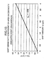
- Fig.13 shows a relationship between the shift amount s x given to the simulated first lens surface and the value C X(1-s) of the apex decentricity of the simulated first lens surface.
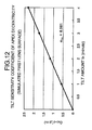
- Fig. 14 shows a relationship between the tilt amount t u given to the simulated second lens surface and the value C U(1-t) of the apex decentricity of the simulated second lens surface at the tilt amount t u , wherein U indicates that the value represents the apex decentricity in the U axis direction of the second coordinate system for measurement).
- U indicates that the value represents the apex decentricity in the U axis direction of the second coordinate system for measurement.
- Fig.12 there is a proportional relationship as expressed by the following formula (23) between the values C U(1-t) and t u , wherein the proportionality coefficient c tu was determined to be -2.9346.
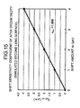
- Fig.15 shows a relationship between the shift amount s u given to the simulated second lens surface and the value C U(1-s) of the apex decentricity of the simulated second lens surface.
- the value C X(1-s , t) of the apex decentricity of the simulated first lens surface which is measured when the tilt amount t x and the shift amount s x are given to the simulated first lens surface at the same time, has a relationship expressed by the following formula (31) with respect to the above-mentioned values C X(1-t) and C X(1-s) , and that the value C Y(1-s , t) of the apex decentricity of the simulated first lens surface while the tilt amount t y and the shift amount s y being simultaneously given to the simulated first lens surface has a relationship with the above-mentioned values C Y(1-t) and C Y(1-s) , which can be expressed by the following formula (32):
- C X ⁇ 1 - s , t C X ⁇ 1 - s + C X ⁇ 1 - t C Y ⁇ 1
- the value C U(1-s, t) of the apex decentricity of the simulated second lens surface which is measured when the tilt amount t u and the shift amount s u are given to the simulated second lens surface at the same time, has a relationship expressed by the following formula (33) with respect to the above-mentioned values C U(1-t) and C U(1-s) , and that the value C V(1-s, t) of the apex decentricity of the simulated second lens surface while the tilt amount t v and the shift amount s v being simultaneously given to the simulated second lens surface has a relationship with the above-mentioned values C V(1-t) and C V(1-s) , which can be expressed by the following formula (34):
- Fig.16 shows results of measurements of shift amounts measured according to the present invention while shifting the simulated first lens surface in the X and Y directions stepwise by respectively predetermined amounts (by 1 ⁇ m in the X direction, and 0.5 ⁇ m in the Y direction).
- the horizontal line indicates the input shift amount P
- the vertical line indicates the output shift amount Q that is calculated according to the measuring method of the present invention.
- the results in the X direction are shown in a negative area of the graph, while the results in the Y direction are shown in a positive area of the graph.
- Linear equations written in the graph approximate the relationship between the input P and the output Q. Without any measurement errors, the output Q will be equal to the input P.
- the measurement errors in the method of the present invention were about 0.9%, verifying the high accuracy of the method of the present invention.
- Fig.17 shows results of measurements of shift amounts measured according to the present invention while shifting the simulated second lens surface in the U and V directions stepwise by respectively predetermined amounts (by 1 ⁇ m in the U direction, and 0.5 ⁇ m in the V direction).
- the horizontal line indicates the input shift amount P
- the vertical line indicates the output shift amount Q that is calculated according to the measuring method of the present invention.
- the results in the U direction are shown in a negative area of the graph, while the results in the V direction are shown in a positive area of the graph.
- Linear equations written in the graph approximate the relationship between the input P and the output Q. Without any measurement errors, the output Q will be equal to the input P.
- the measurement errors in the method of the present invention were about 2.8%, verifying the high accuracy of the method of the present invention.
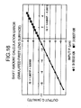
- Fig. 18 shows results of measurements of tilt amounts measured according to the present invention while tilting the simulated first lens surface in the X and Y directions stepwise by respectively predetermined amounts (by 0.5 minutes in the X direction, and 1 minute in the Y direction).
- the horizontal line indicates the input tilt amount J
- the vertical line indicates the output tilt amount K that is calculated according to the measuring method of the present invention.
- the results in the X direction are shown in a positive area of the graph, while the results in the Y direction are shown in a negative area of the graph.
- Linear equations written in the graph approximate the relationship between the input J and the output K. Without any measurement errors, the output K will be equal to the input J. As seen from the linear equations, the measurement errors in the method of the present invention were about 0.8%, verifying the high accuracy of the method of the present invention.
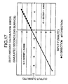
- Fig. 19 shows results of measurements of tilt amounts measured according to the present invention while tilting the simulated second lens surface in the U and V directions stepwise by respectively predetermined amounts (by 0.5 minutes in the U direction, and 1 minute in the V direction).
- the horizontal line indicates the input tilt amount J
- the vertical line indicates the output tilt amount K that is calculated according to the measuring method of the present invention.
- the results in the U direction are shown in a positive area of the graph, while the results in the V direction are shown in a negative area of the graph.
- Linear equations written in the graph approximate the relationship between the input J and the output K. Without any measurement errors, the output K will be equal to the input J.
- the measurement errors in the method of the present invention were about 1.9%, verifying the high accuracy of the method of the present invention.
- the present invention is applicable to such a lens having an aspheric surface and a spherical surface, although the first and second lens surfaces 91 and 92 are both rotationally symmetric aspheric surfaces in the above embodiment.
- the second lens surface 92 is spherical, only the shift amount will be measured with respect to the second measuring optical axis L2, but no tilt amount will be provided for the spherical surface. Therefore, as for the spherical surface, the above-described tilt amount calculation step should be carried out on the assumption that the tilt amount is zero.
- first and second lens surfaces 91 and 92 are relative, so that it is possible to regard the first lens surface 91 as the second specimen surface and the second lens surface 92 as the first specimen surface.
- the present invention is applicable to a case where the second lens surface 92 is a rotationally symmetric aspheric surface and the first lens surface 91 is spherical.
- the first measuring beam projected from the first interferometer 1A onto the first lens surface 91 and the second measuring beam projected from the second interferometer 1B onto the second lens surface 92 are spherical waves.
- the objective lenses 18A and 18B may be omitted to serve the parallel beam (plane waves) as the first and second measuring beams.
- microscopic interferometers using Mireau type objective optics or Michelson type objective optics may be used as the first and second interferometers. This embodiment is preferable when the aspheric lens to inspect is small.
- the present invention may be used to measure an aspheric mirror that has a rotationally symmetric aspheric first mirror surface and a rotationally symmetric aspheric or spherical second mirror surface.
- the reflectance of the mirror surfaces may be high.
- the reflectance of the mirror surface is 100%
- the reflectance of the reference standard flat surface 15Aa or 15Ba may preferably be set to be around 50%, i.e. the transmittance around 50%.
Landscapes
- Physics & Mathematics (AREA)
- General Physics & Mathematics (AREA)
- Chemical & Material Sciences (AREA)
- Analytical Chemistry (AREA)
- Geometry (AREA)
- Optics & Photonics (AREA)
- Length Measuring Devices By Optical Means (AREA)
- Instruments For Measurement Of Length By Optical Means (AREA)
- Testing Of Optical Devices Or Fibers (AREA)
Claims (3)
- Procédé de mesure du décentrement et de l'inclinaison d'une première surface de spécimen (91) d'un objet asphérique (9) par rapport à une seconde surface de spécimen (92) dudit objet asphérique à l'aide de premier et second interféromètres (1A, 1B), dans lequel ladite première surface de spécimen est une surface asphérique symétrique sur le plan rotationnel et ladite seconde surface de spécimen est une surface asphérique symétrique sur le plan rotationnel ou une surface sphérique, et des positions relatives desdits premier et second interféromètres entre eux sont déterminées, le procédé comprenant les étapes pour :projeter un premier faisceau de mesure sur ladite première surface de spécimen le long d'un premier axe optique de mesure (L1) dudit premier interféromètre, afin de capturer des données image de premières franges d'interférence qui sont produites par une interférence optique entre un premier front d'onde de réflexion dudit premier faisceau de mesure tel que réfléchi à partir de ladite première surface de spécimen et un premier front d'onde de référence dudit premier interféromètre ;projeter un second faisceau de mesure sur ladite seconde surface de spécimen le long d'un second axe optique de mesure (L2) dudit second interféromètre, afin de capturer des données image de secondes franges d'interférence qui sont produites par une interférence optique entre un second front d'onde de réflexion dudit second faisceau de mesure tel que réfléchi à partir de ladite seconde surface de spécimen et un second front d'onde de référence dudit second interféromètre ;analyser les données image desdites premières franges d'interférence afin d'acquérir des données géométriques de ladite première surface de spécimen ;analyser les données image desdites secondes franges d'interférence afin d'acquérir des données géométriques de ladite seconde surface de spécimen ;effectuer une approximation desdites données géométriques de ladite première surface de spécimen avec un polynôme de Zernike afin de calculer, parmi des coefficients de termes respectifs du polynôme de Zernike, une valeur d'un premier coefficient de proportionnalité pour une quantité de décalage qui est de proportion variable par rapport à une quantité de décalage de ladite première surface de spécimen dans une direction perpendiculaire audit premier axe optique de mesure et une valeur d'un premier coefficient de proportionnalité pour une quantité d'inclinaison qui est de proportion variable par rapport à une quantité d'inclinaison de ladite première surface de spécimen par rapport audit premier axe optique de mesure ;effectuer une approximation desdites données géométriques de ladite seconde surface de spécimen avec un polynôme de Zernike afin de calculer, parmi des coefficients de termes respectifs du polynôme de Zernike, une valeur d'un second coefficient de proportionnalité pour une quantité de décalage qui est de proportion variable par rapport à une quantité de décalage de ladite seconde surface de spécimen dans une direction perpendiculaire audit second axe optique de mesure et une valeur d'un second coefficient de proportionnalité pour une quantité d'inclinaison qui est de proportion variable par rapport à une quantité d'inclinaison de ladite seconde surface de spécimen par rapport audit second axe optique de mesure ;calculer une valeur d'excentricité d'un sommet de ladite première surface de spécimen par rapport audit premier axe optique de mesure sur la base desdites données géométriques de ladite première surface de spécimen, la valeur d'excentricité de sommet variant avec la quantité de décalage de ladite première surface de spécimen dans la direction perpendiculaire audit premier axe optique de mesure et avec la quantité d'inclinaison de ladite première surface de spécimen par rapport audit premier axe optique de mesure ;calculer une valeur d'excentricité d'un sommet de ladite seconde surface de spécimen par rapport audit second axe optique de mesure sur la base desdites données géométriques de ladite seconde surface de spécimen, la valeur d'excentricité de sommet variant avec la quantité de décalage de ladite seconde surface de spécimen dans la direction perpendiculaire audit second axe optique de mesure et avec la quantité d'inclinaison de ladite seconde surface de spécimen par rapport audit second axe optique de mesure ;calculer une quantité de décalage (sx,sy) et une quantité d'inclinaison (tx, ty) de ladite première surface de spécimen par rapport audit premier axe optique de mesure sur la base des valeurs dudit premier coefficient de proportionnalité pour la quantité de décalage, dudit premier coefficient de proportionnalité pour la quantité d'inclinaison, et de ladite excentricité de sommet de ladite première surface de spécimen ;calculer une quantité de décalage (su,sv) et une quantité d'inclinaison (tu, tv) de ladite seconde surface de spécimen par rapport audit second axe optique de mesure sur la base des valeurs dudit second coefficient de proportionnalité pour la quantité de décalage, dudit second coefficient de proportionnalité pour la quantité d'inclinaison, et de ladite excentricité de sommet de ladite seconde surface de spécimen, etcalculer des quantités de décentrement et d'inclinaison relatifs de ladite première surface de spécimen par rapport à ladite seconde surface de spécimen sur la base de la quantité de décalage et de la quantité d'inclinaison de ladite première surface de spécimen, de la quantité de décalage et de la quantité d'inclinaison de ladite seconde surface de spécimen, et des informations sur les positions relatives desdits premier et second interféromètres.
- Procédé selon la revendication 1, dans lequel ledit polynôme de Zernike est un polynôme de Zernike Z(ρ, θ) de quatrième ordre ou plus qui est exprimé sous la forme de coordonnées polaires, ρ et θ représentant une distance respectivement à partir d'un pôle et un angle d'inclinaison par rapport à une ligne initiale, et dans lequel ledit premier coefficient de proportionnalité pour la quantité de décalage et ledit second coefficient de proportionnalité pour la quantité de décalage sont un coefficient Z1 d'un terme exprimé par la formule suivante (1) et un coefficient Z2 d'un terme exprimé par la formule suivante (2) :


- Appareil de mesure du décentrement et de l'inclinaison d'une première surface de spécimen (91) d'un objet asphérique (9) par rapport à une seconde surface de spécimen (92) dudit objet asphérique, dans lequel ladite première surface de spécimen est une surface asphérique symétrique sur le plan rotationnel et ladite seconde surface de spécimen est une surface asphérique symétrique sur le plan rotationnel ou une surface sphérique, ledit appareil comprenant :un premier interféromètre (1A) configuré pour projeter un premier faisceau de mesure sur ladite première surface de spécimen le long d'un premier axe optique de mesure (L1), afin de capturer des données image de premières franges d'interférence qui sont produites par une interférence optique entre un premier front d'onde de réflexion dudit premier faisceau de mesure tel que réfléchi à partir de ladite première surface de spécimen et un premier front d'onde de référence dudit premier interféromètre ;un second interféromètre (1B) configuré pour projeter un second faisceau de mesure sur ladite seconde surface de spécimen le long d'un second axe optique de mesure (L2), afin de capturer des données image de secondes franges d'interférence qui sont produites par une interférence optique entre un second front d'onde de réflexion dudit second faisceau de mesure tel que réfléchi à partir de ladite seconde surface de spécimen et un second front d'onde de référence dudit second interféromètre, dans lequel la position dudit second interféromètre par rapport audit premier interféromètre est déterminée ;un premier dispositif d'acquisition de donnés géométriques de surface de spécimen (51A) configuré pour analyser les données image desdites premières franges d'interférence afin d'acquérir des données géométriques de ladite première surface de spécimen ;un second dispositif d'acquisition de donnés géométriques de surface de spécimen (51B) configuré pour analyser les données image desdites secondes franges d'interférence afin d'acquérir des données géométriques de ladite seconde surface de spécimen ;un premier calculateur de coefficient de Zernike (52A) configuré pour effectuer une approximation desdites données géométriques de ladite première surface de spécimen avec un polynôme de Zernike afin de calculer, parmi des coefficients de termes respectifs du polynôme de Zernike, une valeur d'un premier coefficient de proportionnalité pour une quantité de décalage qui est de proportion variable par rapport à une quantité de décalage de ladite première surface de spécimen dans une direction perpendiculaire audit premier axe optique de mesure et une valeur d'un premier coefficient de proportionnalité pour une quantité d'inclinaison qui est de proportion variable par rapport à une quantité d'inclinaison de ladite première surface de spécimen par rapport audit premier axe optique de mesure ;un second calculateur de coefficient de Zernike (52B) configuré pour effectuer une approximation desdites données géométriques de ladite seconde surface de spécimen avec un polynôme de Zernike afin de calculer, parmi des coefficients de termes respectifs du polynôme de Zernike, une valeur d'un second coefficient de proportionnalité pour une quantité de décalage qui est de proportion variable par rapport à une quantité de décalage de ladite seconde surface de spécimen dans une direction perpendiculaire audit second axe optique de mesure et une valeur d'un second coefficient de proportionnalité pour une quantité d'inclinaison qui est de proportion variable par rapport à une quantité d'inclinaison de ladite seconde surface de spécimen par rapport audit second axe optique de mesure ;un premier calculateur d'excentricité de sommet (53A) configuré pour calculer une valeur d'excentricité d'un sommet de ladite première surface de spécimen par rapport audit premier axe optique de mesure sur la base desdites données géométriques de ladite première surface de spécimen, la valeur d'excentricité de sommet variant avec la quantité de décalage de ladite première surface de spécimen dans la direction perpendiculaire audit premier axe optique de mesure et avec la quantité d'inclinaison de ladite première surface de spécimen par rapport audit premier axe optique de mesure ;un second calculateur d'excentricité de sommet (53B) configuré pour calculer une valeur d'excentricité d'un sommet de ladite seconde surface de spécimen par rapport audit second axe optique de mesure sur la base desdites données géométriques de ladite seconde surface de spécimen, la valeur d'excentricité de sommet variant avec la quantité de décalage de ladite seconde surface de spécimen dans la direction perpendiculaire audit second axe optique de mesure et avec la quantité d'inclinaison de ladite seconde surface de spécimen par rapport audit second axe optique de mesure ;un premier calculateur de quantité de décalage et d'inclinaison (54A) configuré pour calculer une quantité de décalage et une quantité d'inclinaison de ladite première surface de spécimen par rapport audit premier axe optique de mesure sur la base des valeurs dudit premier coefficient de proportionnalité pour la quantité de décalage, dudit premier coefficient de proportionnalité pour la quantité d'inclinaison, et de ladite excentricité de sommet de ladite première surface de spécimen ;un second calculateur de quantité de décalage et d'inclinaison (54B) configuré pour calculer une quantité de décalage et une quantité d'inclinaison de ladite seconde surface de spécimen par rapport audit second axe optique de mesure sur la base des valeurs dudit second coefficient de proportionnalité pour la quantité de décalage, dudit second coefficient de proportionnalité pour la quantité d'inclinaison, et de ladite excentricité de sommet de ladite seconde surface de spécimen, etun dispositif (55) configuré pour déterminer des quantités de décentrement et d'inclinaison relatifs de ladite première surface de spécimen par rapport à ladite seconde surface de spécimen sur la base de la quantité de décalage et de la quantité d'inclinaison de ladite première surface de spécimen, de la quantité de décalage et de la quantité d'inclinaison de ladite seconde surface de spécimen, et des informations sur le position relative dudit premier interféromètre par rapport au second interféromètre.
Applications Claiming Priority (1)
| Application Number | Priority Date | Filing Date | Title |
|---|---|---|---|
| JP2010067007A JP5399304B2 (ja) | 2010-03-23 | 2010-03-23 | 非球面体測定方法および装置 |
Publications (3)
| Publication Number | Publication Date |
|---|---|
| EP2369319A2 EP2369319A2 (fr) | 2011-09-28 |
| EP2369319A3 EP2369319A3 (fr) | 2012-06-20 |
| EP2369319B1 true EP2369319B1 (fr) | 2015-07-29 |
Family
ID=44202207
Family Applications (1)
| Application Number | Title | Priority Date | Filing Date |
|---|---|---|---|
| EP11159211.9A Not-in-force EP2369319B1 (fr) | 2010-03-23 | 2011-03-22 | Procédé et dispositif de mesure d'objets asphériques |
Country Status (4)
| Country | Link |
|---|---|
| EP (1) | EP2369319B1 (fr) |
| JP (1) | JP5399304B2 (fr) |
| KR (1) | KR20110106823A (fr) |
| CN (1) | CN102200432A (fr) |
Families Citing this family (17)
| Publication number | Priority date | Publication date | Assignee | Title |
|---|---|---|---|---|
| CN102620917A (zh) * | 2012-04-11 | 2012-08-01 | 长春理工大学 | 透射式光学元件光致热变形像质分析方法 |
| EP2920568B1 (fr) * | 2012-11-14 | 2018-05-16 | Essilor International | Procédé de détermination des paramètres optiques d'un verre ophtalmique |
| MX344975B (es) | 2012-11-14 | 2017-01-12 | Essilor Int | Metodo para determinar la viabilidad de una lente oftalmica. |
| KR101421502B1 (ko) * | 2014-04-08 | 2014-07-22 | 경남대학교 산학협력단 | 국부영역의 이차미분을 이용한 광학식 자유곡면 형상 측정 방법 및 이를 이용한 곡면 형상 측정 시스템 |
| DE102014208636B4 (de) * | 2014-05-08 | 2018-06-28 | Asphericon Gmbh | Verfahren und Vorrichtung zur Messung einer Dezentrierung und Verkippung von Flächen eines optischen Elements |
| JP6427982B2 (ja) * | 2014-06-20 | 2018-11-28 | コニカミノルタ株式会社 | 測定装置 |
| JP5870234B1 (ja) * | 2014-07-03 | 2016-02-24 | オリンパス株式会社 | 偏心量計測方法及び偏心量計測装置 |
| WO2016157291A1 (fr) * | 2015-03-27 | 2016-10-06 | オリンパス株式会社 | Tête de mesure et dispositif de mesure d'eccentricité pourvu de celle-ci |
| CN106595473A (zh) * | 2016-09-29 | 2017-04-26 | 浙江科技学院(浙江中德科技促进中心) | 非球面模具的在位测量系统及其测量方法和测量检验方法 |
| DE102017129118A1 (de) * | 2017-12-07 | 2019-06-13 | Carl Zeiss Jena Gmbh | Verfahren, Vorrichtung und Computerprogramm zur Lagebestimmung eines optischen Prüflings und zur Messung der optischen Mittendicke |
| CN109580179B (zh) | 2018-11-22 | 2021-01-08 | 中国科学院苏州生物医学工程技术研究所 | 基于波前技术的非球面透镜偏心检测装置及其检测方法 |
| CN110319793B (zh) * | 2019-08-06 | 2024-03-22 | 清华大学深圳研究生院 | 一种透射旋转对称非球面检测系统和方法 |
| CN111259588B (zh) * | 2020-01-16 | 2020-10-30 | 中国科学院西安光学精密机械研究所 | 一种多物理场耦合作用下反射镜光学表面误差的获取方法 |
| CN112629436B (zh) * | 2020-11-20 | 2021-11-19 | 西安交通大学 | 一种基于自适应光学波前校正的高次非球面检测方法 |
| CN113503830B (zh) * | 2021-07-05 | 2023-01-03 | 无锡维度投资管理合伙企业(有限合伙) | 一种基于多相机的非球面面形测量方法 |
| EP4377662A1 (fr) * | 2021-07-28 | 2024-06-05 | Zygo Corporation | Aligneur de lentille interférométrique et procédé |
| FR3128013B1 (fr) * | 2021-10-08 | 2023-11-03 | Fogale Nanotech | Procédé et dispositif de mesure d’interfaces d’un élément optique |
Family Cites Families (7)
| Publication number | Priority date | Publication date | Assignee | Title |
|---|---|---|---|---|
| JP3352298B2 (ja) * | 1995-09-29 | 2002-12-03 | キヤノン株式会社 | レンズ性能測定方法及びそれを用いたレンズ性能測定装置 |
| US7218403B2 (en) * | 2002-06-26 | 2007-05-15 | Zygo Corporation | Scanning interferometer for aspheric surfaces and wavefronts |
| JP5025106B2 (ja) * | 2005-07-28 | 2012-09-12 | Hoya株式会社 | 偏心測定方法、偏心測定装置及び非球面単レンズの製造方法 |
| JP2008249215A (ja) * | 2007-03-29 | 2008-10-16 | Nec Corp | 縦型加熱炉 |
| JP4880513B2 (ja) * | 2007-03-29 | 2012-02-22 | 富士フイルム株式会社 | 非球面レンズの面ずれ測定方法および装置 |
| JP2009145081A (ja) * | 2007-12-11 | 2009-07-02 | Fujinon Corp | 回転非対称収差の発生要因誤差量測定方法および装置 |
| JP2011122857A (ja) * | 2009-12-08 | 2011-06-23 | Fujifilm Corp | 非球面体測定方法および装置 |
-
2010
- 2010-03-23 JP JP2010067007A patent/JP5399304B2/ja not_active Expired - Fee Related
-
2011
- 2011-03-22 EP EP11159211.9A patent/EP2369319B1/fr not_active Not-in-force
- 2011-03-23 CN CN2011100769960A patent/CN102200432A/zh active Pending
- 2011-03-23 KR KR1020110025769A patent/KR20110106823A/ko not_active Application Discontinuation
Also Published As
| Publication number | Publication date |
|---|---|
| EP2369319A2 (fr) | 2011-09-28 |
| JP5399304B2 (ja) | 2014-01-29 |
| EP2369319A3 (fr) | 2012-06-20 |
| KR20110106823A (ko) | 2011-09-29 |
| JP2011196954A (ja) | 2011-10-06 |
| CN102200432A (zh) | 2011-09-28 |
Similar Documents
| Publication | Publication Date | Title |
|---|---|---|
| EP2369319B1 (fr) | Procédé et dispositif de mesure d'objets asphériques | |
| KR100972571B1 (ko) | 비구면 렌즈의 면 어긋남 측정 방법 및 장치 | |
| CN104391366B (zh) | 一种太赫兹波段离轴三反射镜系统及其装调方法 | |
| EP2261629A2 (fr) | Procédé et appareil de mesure de sphère | |
| JP6000577B2 (ja) | 非球面計測方法、非球面計測装置、光学素子加工装置および光学素子の製造方法 | |
| JP5896792B2 (ja) | 非球面計測方法、非球面計測装置および光学素子加工装置 | |
| US20170074648A1 (en) | Method for calibrating a measuring device | |
| JP7204428B2 (ja) | 偏心計測方法、レンズ製造方法、および偏心計測装置 | |
| KR20110065365A (ko) | 비구면체 측정 방법 및 장치 | |
| CN110207587B (zh) | 一种角锥棱镜光学顶点的测量方法 | |
| WO2012132930A1 (fr) | Dispositif de mesure de lentille | |
| JP2009145081A (ja) | 回転非対称収差の発生要因誤差量測定方法および装置 | |
| JP2576576B2 (ja) | 干渉測定方法及びそれを利用したフィゾー干渉測定装置 | |
| JP2005201703A (ja) | 干渉測定方法及び干渉測定システム | |
| JP4768904B2 (ja) | 光学素子又は光学系の物理量測定方法 | |
| JP4802134B2 (ja) | 姿勢変化測定方法および装置 | |
| JP4007473B2 (ja) | 波面形状測定方法 | |
| TWI596325B (zh) | 決定物體或透明光學元件的資訊的方法與系統以及形成光學組件方法 | |
| JP2001227929A (ja) | 角度測定方法及び角度測定装置 | |
| JP2016017744A (ja) | 非球面計測方法、非球面計測装置、プログラム、光学素子の加工装置、および、光学素子 | |
| JP2012215426A (ja) | レンズの面ズレ・面倒れを測定するレンズ測定装置 | |
| JP6821407B2 (ja) | 計測方法、計測装置、光学機器の製造方法および光学機器の製造装置 | |
| JP2017072447A (ja) | 位置算出方法、形状計測方法、形状計測装置、プログラム、記録媒体及び部品の製造方法 | |
| JP2021001746A (ja) | 形状計測方法、レンズの製造方法、および形状計測装置 | |
| CN116448000A (zh) | 一种非球面面形误差检测与数据处理方法 |
Legal Events
| Date | Code | Title | Description |
|---|---|---|---|
| PUAI | Public reference made under article 153(3) epc to a published international application that has entered the european phase |
Free format text: ORIGINAL CODE: 0009012 |
|
| AK | Designated contracting states |
Kind code of ref document: A2 Designated state(s): AL AT BE BG CH CY CZ DE DK EE ES FI FR GB GR HR HU IE IS IT LI LT LU LV MC MK MT NL NO PL PT RO RS SE SI SK SM TR |
|
| AX | Request for extension of the european patent |
Extension state: BA ME |
|
| PUAL | Search report despatched |
Free format text: ORIGINAL CODE: 0009013 |
|
| AK | Designated contracting states |
Kind code of ref document: A3 Designated state(s): AL AT BE BG CH CY CZ DE DK EE ES FI FR GB GR HR HU IE IS IT LI LT LU LV MC MK MT NL NO PL PT RO RS SE SI SK SM TR |
|
| AX | Request for extension of the european patent |
Extension state: BA ME |
|
| RIC1 | Information provided on ipc code assigned before grant |
Ipc: G01B 11/24 20060101ALI20120511BHEP Ipc: G01M 11/02 20060101AFI20120511BHEP |
|
| 17P | Request for examination filed |
Effective date: 20120808 |
|
| GRAP | Despatch of communication of intention to grant a patent |
Free format text: ORIGINAL CODE: EPIDOSNIGR1 |
|
| INTG | Intention to grant announced |
Effective date: 20150203 |
|
| GRAS | Grant fee paid |
Free format text: ORIGINAL CODE: EPIDOSNIGR3 |
|
| GRAA | (expected) grant |
Free format text: ORIGINAL CODE: 0009210 |
|
| AK | Designated contracting states |
Kind code of ref document: B1 Designated state(s): AL AT BE BG CH CY CZ DE DK EE ES FI FR GB GR HR HU IE IS IT LI LT LU LV MC MK MT NL NO PL PT RO RS SE SI SK SM TR |
|
| REG | Reference to a national code |
Ref country code: GB Ref legal event code: FG4D |
|
| REG | Reference to a national code |
Ref country code: CH Ref legal event code: EP |
|
| REG | Reference to a national code |
Ref country code: AT Ref legal event code: REF Ref document number: 739684 Country of ref document: AT Kind code of ref document: T Effective date: 20150815 |
|
| REG | Reference to a national code |
Ref country code: IE Ref legal event code: FG4D |
|
| REG | Reference to a national code |
Ref country code: DE Ref legal event code: R096 Ref document number: 602011018152 Country of ref document: DE |
|
| REG | Reference to a national code |
Ref country code: AT Ref legal event code: MK05 Ref document number: 739684 Country of ref document: AT Kind code of ref document: T Effective date: 20150729 |
|
| REG | Reference to a national code |
Ref country code: LT Ref legal event code: MG4D |
|
| REG | Reference to a national code |
Ref country code: NL Ref legal event code: MP Effective date: 20150729 |
|
| PG25 | Lapsed in a contracting state [announced via postgrant information from national office to epo] |
Ref country code: LT Free format text: LAPSE BECAUSE OF FAILURE TO SUBMIT A TRANSLATION OF THE DESCRIPTION OR TO PAY THE FEE WITHIN THE PRESCRIBED TIME-LIMIT Effective date: 20150729 Ref country code: GR Free format text: LAPSE BECAUSE OF FAILURE TO SUBMIT A TRANSLATION OF THE DESCRIPTION OR TO PAY THE FEE WITHIN THE PRESCRIBED TIME-LIMIT Effective date: 20151030 Ref country code: FI Free format text: LAPSE BECAUSE OF FAILURE TO SUBMIT A TRANSLATION OF THE DESCRIPTION OR TO PAY THE FEE WITHIN THE PRESCRIBED TIME-LIMIT Effective date: 20150729 Ref country code: NO Free format text: LAPSE BECAUSE OF FAILURE TO SUBMIT A TRANSLATION OF THE DESCRIPTION OR TO PAY THE FEE WITHIN THE PRESCRIBED TIME-LIMIT Effective date: 20151029 Ref country code: LV Free format text: LAPSE BECAUSE OF FAILURE TO SUBMIT A TRANSLATION OF THE DESCRIPTION OR TO PAY THE FEE WITHIN THE PRESCRIBED TIME-LIMIT Effective date: 20150729 |
|
| PG25 | Lapsed in a contracting state [announced via postgrant information from national office to epo] |
Ref country code: SE Free format text: LAPSE BECAUSE OF FAILURE TO SUBMIT A TRANSLATION OF THE DESCRIPTION OR TO PAY THE FEE WITHIN THE PRESCRIBED TIME-LIMIT Effective date: 20150729 Ref country code: RS Free format text: LAPSE BECAUSE OF FAILURE TO SUBMIT A TRANSLATION OF THE DESCRIPTION OR TO PAY THE FEE WITHIN THE PRESCRIBED TIME-LIMIT Effective date: 20150729 Ref country code: ES Free format text: LAPSE BECAUSE OF FAILURE TO SUBMIT A TRANSLATION OF THE DESCRIPTION OR TO PAY THE FEE WITHIN THE PRESCRIBED TIME-LIMIT Effective date: 20150729 Ref country code: PL Free format text: LAPSE BECAUSE OF FAILURE TO SUBMIT A TRANSLATION OF THE DESCRIPTION OR TO PAY THE FEE WITHIN THE PRESCRIBED TIME-LIMIT Effective date: 20150729 Ref country code: IS Free format text: LAPSE BECAUSE OF FAILURE TO SUBMIT A TRANSLATION OF THE DESCRIPTION OR TO PAY THE FEE WITHIN THE PRESCRIBED TIME-LIMIT Effective date: 20151129 Ref country code: AT Free format text: LAPSE BECAUSE OF FAILURE TO SUBMIT A TRANSLATION OF THE DESCRIPTION OR TO PAY THE FEE WITHIN THE PRESCRIBED TIME-LIMIT Effective date: 20150729 Ref country code: HR Free format text: LAPSE BECAUSE OF FAILURE TO SUBMIT A TRANSLATION OF THE DESCRIPTION OR TO PAY THE FEE WITHIN THE PRESCRIBED TIME-LIMIT Effective date: 20150729 Ref country code: PT Free format text: LAPSE BECAUSE OF FAILURE TO SUBMIT A TRANSLATION OF THE DESCRIPTION OR TO PAY THE FEE WITHIN THE PRESCRIBED TIME-LIMIT Effective date: 20151130 |
|
| PG25 | Lapsed in a contracting state [announced via postgrant information from national office to epo] |
Ref country code: NL Free format text: LAPSE BECAUSE OF FAILURE TO SUBMIT A TRANSLATION OF THE DESCRIPTION OR TO PAY THE FEE WITHIN THE PRESCRIBED TIME-LIMIT Effective date: 20150729 |
|
| PG25 | Lapsed in a contracting state [announced via postgrant information from national office to epo] |
Ref country code: DK Free format text: LAPSE BECAUSE OF FAILURE TO SUBMIT A TRANSLATION OF THE DESCRIPTION OR TO PAY THE FEE WITHIN THE PRESCRIBED TIME-LIMIT Effective date: 20150729 Ref country code: IT Free format text: LAPSE BECAUSE OF FAILURE TO SUBMIT A TRANSLATION OF THE DESCRIPTION OR TO PAY THE FEE WITHIN THE PRESCRIBED TIME-LIMIT Effective date: 20150729 Ref country code: SK Free format text: LAPSE BECAUSE OF FAILURE TO SUBMIT A TRANSLATION OF THE DESCRIPTION OR TO PAY THE FEE WITHIN THE PRESCRIBED TIME-LIMIT Effective date: 20150729 Ref country code: EE Free format text: LAPSE BECAUSE OF FAILURE TO SUBMIT A TRANSLATION OF THE DESCRIPTION OR TO PAY THE FEE WITHIN THE PRESCRIBED TIME-LIMIT Effective date: 20150729 Ref country code: CZ Free format text: LAPSE BECAUSE OF FAILURE TO SUBMIT A TRANSLATION OF THE DESCRIPTION OR TO PAY THE FEE WITHIN THE PRESCRIBED TIME-LIMIT Effective date: 20150729 |
|
| REG | Reference to a national code |
Ref country code: DE Ref legal event code: R097 Ref document number: 602011018152 Country of ref document: DE |
|
| PG25 | Lapsed in a contracting state [announced via postgrant information from national office to epo] |
Ref country code: RO Free format text: LAPSE BECAUSE OF FAILURE TO SUBMIT A TRANSLATION OF THE DESCRIPTION OR TO PAY THE FEE WITHIN THE PRESCRIBED TIME-LIMIT Effective date: 20150729 |
|
| PLBE | No opposition filed within time limit |
Free format text: ORIGINAL CODE: 0009261 |
|
| STAA | Information on the status of an ep patent application or granted ep patent |
Free format text: STATUS: NO OPPOSITION FILED WITHIN TIME LIMIT |
|
| 26N | No opposition filed |
Effective date: 20160502 |
|
| PG25 | Lapsed in a contracting state [announced via postgrant information from national office to epo] |
Ref country code: SI Free format text: LAPSE BECAUSE OF FAILURE TO SUBMIT A TRANSLATION OF THE DESCRIPTION OR TO PAY THE FEE WITHIN THE PRESCRIBED TIME-LIMIT Effective date: 20150729 Ref country code: BE Free format text: LAPSE BECAUSE OF NON-PAYMENT OF DUE FEES Effective date: 20160331 |
|
| REG | Reference to a national code |
Ref country code: DE Ref legal event code: R119 Ref document number: 602011018152 Country of ref document: DE |
|
| PG25 | Lapsed in a contracting state [announced via postgrant information from national office to epo] |
Ref country code: MC Free format text: LAPSE BECAUSE OF FAILURE TO SUBMIT A TRANSLATION OF THE DESCRIPTION OR TO PAY THE FEE WITHIN THE PRESCRIBED TIME-LIMIT Effective date: 20150729 Ref country code: LU Free format text: LAPSE BECAUSE OF FAILURE TO SUBMIT A TRANSLATION OF THE DESCRIPTION OR TO PAY THE FEE WITHIN THE PRESCRIBED TIME-LIMIT Effective date: 20160322 |
|
| REG | Reference to a national code |
Ref country code: CH Ref legal event code: PL |
|
| GBPC | Gb: european patent ceased through non-payment of renewal fee |
Effective date: 20160322 |
|
| REG | Reference to a national code |
Ref country code: IE Ref legal event code: MM4A |
|
| PG25 | Lapsed in a contracting state [announced via postgrant information from national office to epo] |
Ref country code: BE Free format text: LAPSE BECAUSE OF FAILURE TO SUBMIT A TRANSLATION OF THE DESCRIPTION OR TO PAY THE FEE WITHIN THE PRESCRIBED TIME-LIMIT Effective date: 20150729 |
|
| REG | Reference to a national code |
Ref country code: FR Ref legal event code: ST Effective date: 20161130 |
|
| PG25 | Lapsed in a contracting state [announced via postgrant information from national office to epo] |
Ref country code: FR Free format text: LAPSE BECAUSE OF NON-PAYMENT OF DUE FEES Effective date: 20160331 Ref country code: DE Free format text: LAPSE BECAUSE OF NON-PAYMENT OF DUE FEES Effective date: 20161001 Ref country code: IE Free format text: LAPSE BECAUSE OF NON-PAYMENT OF DUE FEES Effective date: 20160322 Ref country code: LI Free format text: LAPSE BECAUSE OF NON-PAYMENT OF DUE FEES Effective date: 20160331 Ref country code: GB Free format text: LAPSE BECAUSE OF NON-PAYMENT OF DUE FEES Effective date: 20160322 Ref country code: CH Free format text: LAPSE BECAUSE OF NON-PAYMENT OF DUE FEES Effective date: 20160331 |
|
| PG25 | Lapsed in a contracting state [announced via postgrant information from national office to epo] |
Ref country code: MT Free format text: LAPSE BECAUSE OF FAILURE TO SUBMIT A TRANSLATION OF THE DESCRIPTION OR TO PAY THE FEE WITHIN THE PRESCRIBED TIME-LIMIT Effective date: 20150729 |
|
| PG25 | Lapsed in a contracting state [announced via postgrant information from national office to epo] |
Ref country code: SM Free format text: LAPSE BECAUSE OF FAILURE TO SUBMIT A TRANSLATION OF THE DESCRIPTION OR TO PAY THE FEE WITHIN THE PRESCRIBED TIME-LIMIT Effective date: 20150729 Ref country code: CY Free format text: LAPSE BECAUSE OF FAILURE TO SUBMIT A TRANSLATION OF THE DESCRIPTION OR TO PAY THE FEE WITHIN THE PRESCRIBED TIME-LIMIT Effective date: 20150729 Ref country code: HU Free format text: LAPSE BECAUSE OF FAILURE TO SUBMIT A TRANSLATION OF THE DESCRIPTION OR TO PAY THE FEE WITHIN THE PRESCRIBED TIME-LIMIT; INVALID AB INITIO Effective date: 20110322 |
|
| PG25 | Lapsed in a contracting state [announced via postgrant information from national office to epo] |
Ref country code: MK Free format text: LAPSE BECAUSE OF FAILURE TO SUBMIT A TRANSLATION OF THE DESCRIPTION OR TO PAY THE FEE WITHIN THE PRESCRIBED TIME-LIMIT Effective date: 20150729 Ref country code: MT Free format text: LAPSE BECAUSE OF FAILURE TO SUBMIT A TRANSLATION OF THE DESCRIPTION OR TO PAY THE FEE WITHIN THE PRESCRIBED TIME-LIMIT Effective date: 20160331 Ref country code: TR Free format text: LAPSE BECAUSE OF FAILURE TO SUBMIT A TRANSLATION OF THE DESCRIPTION OR TO PAY THE FEE WITHIN THE PRESCRIBED TIME-LIMIT Effective date: 20150729 |
|
| PG25 | Lapsed in a contracting state [announced via postgrant information from national office to epo] |
Ref country code: BG Free format text: LAPSE BECAUSE OF FAILURE TO SUBMIT A TRANSLATION OF THE DESCRIPTION OR TO PAY THE FEE WITHIN THE PRESCRIBED TIME-LIMIT Effective date: 20150729 |
|
| PG25 | Lapsed in a contracting state [announced via postgrant information from national office to epo] |
Ref country code: AL Free format text: LAPSE BECAUSE OF FAILURE TO SUBMIT A TRANSLATION OF THE DESCRIPTION OR TO PAY THE FEE WITHIN THE PRESCRIBED TIME-LIMIT Effective date: 20150729 |