EP2369108A2 - Türband, insbesondere für gefälzte Gebäudeabschlusstüren aus Holz - Google Patents
Türband, insbesondere für gefälzte Gebäudeabschlusstüren aus Holz Download PDFInfo
- Publication number
- EP2369108A2 EP2369108A2 EP11152019A EP11152019A EP2369108A2 EP 2369108 A2 EP2369108 A2 EP 2369108A2 EP 11152019 A EP11152019 A EP 11152019A EP 11152019 A EP11152019 A EP 11152019A EP 2369108 A2 EP2369108 A2 EP 2369108A2
- Authority
- EP
- European Patent Office
- Prior art keywords
- housing
- door hinge
- receiving element
- clamping plate
- door
- Prior art date
- Legal status (The legal status is an assumption and is not a legal conclusion. Google has not performed a legal analysis and makes no representation as to the accuracy of the status listed.)
- Granted
Links
Images


Classifications
-
- E—FIXED CONSTRUCTIONS
- E05—LOCKS; KEYS; WINDOW OR DOOR FITTINGS; SAFES
- E05D—HINGES OR SUSPENSION DEVICES FOR DOORS, WINDOWS OR WINGS
- E05D7/00—Hinges or pivots of special construction
- E05D7/04—Hinges adjustable relative to the wing or the frame
- E05D7/0415—Hinges adjustable relative to the wing or the frame with adjusting drive means
- E05D7/0423—Screw-and-nut mechanisms
-
- E—FIXED CONSTRUCTIONS
- E05—LOCKS; KEYS; WINDOW OR DOOR FITTINGS; SAFES
- E05D—HINGES OR SUSPENSION DEVICES FOR DOORS, WINDOWS OR WINGS
- E05D7/00—Hinges or pivots of special construction
- E05D7/04—Hinges adjustable relative to the wing or the frame
- E05D2007/0476—Pocket hinges
-
- E—FIXED CONSTRUCTIONS
- E05—LOCKS; KEYS; WINDOW OR DOOR FITTINGS; SAFES
- E05D—HINGES OR SUSPENSION DEVICES FOR DOORS, WINDOWS OR WINGS
- E05D7/00—Hinges or pivots of special construction
- E05D7/04—Hinges adjustable relative to the wing or the frame
- E05D2007/0484—Hinges adjustable relative to the wing or the frame in a radial direction
-
- E—FIXED CONSTRUCTIONS
- E05—LOCKS; KEYS; WINDOW OR DOOR FITTINGS; SAFES
- E05Y—INDEXING SCHEME RELATING TO HINGES OR OTHER SUSPENSION DEVICES FOR DOORS, WINDOWS OR WINGS AND DEVICES FOR MOVING WINGS INTO OPEN OR CLOSED POSITION, CHECKS FOR WINGS AND WING FITTINGS NOT OTHERWISE PROVIDED FOR, CONCERNED WITH THE FUNCTIONING OF THE WING
- E05Y2201/00—Constructional elements; Accessories therefore
- E05Y2201/10—Covers; Housings
-
- E—FIXED CONSTRUCTIONS
- E05—LOCKS; KEYS; WINDOW OR DOOR FITTINGS; SAFES
- E05Y—INDEXING SCHEME RELATING TO HINGES OR OTHER SUSPENSION DEVICES FOR DOORS, WINDOWS OR WINGS AND DEVICES FOR MOVING WINGS INTO OPEN OR CLOSED POSITION, CHECKS FOR WINGS AND WING FITTINGS NOT OTHERWISE PROVIDED FOR, CONCERNED WITH THE FUNCTIONING OF THE WING
- E05Y2201/00—Constructional elements; Accessories therefore
- E05Y2201/60—Suspension or transmission members; Accessories therefore
- E05Y2201/622—Suspension or transmission members elements
- E05Y2201/638—Cams; Ramps
-
- E—FIXED CONSTRUCTIONS
- E05—LOCKS; KEYS; WINDOW OR DOOR FITTINGS; SAFES
- E05Y—INDEXING SCHEME RELATING TO HINGES OR OTHER SUSPENSION DEVICES FOR DOORS, WINDOWS OR WINGS AND DEVICES FOR MOVING WINGS INTO OPEN OR CLOSED POSITION, CHECKS FOR WINGS AND WING FITTINGS NOT OTHERWISE PROVIDED FOR, CONCERNED WITH THE FUNCTIONING OF THE WING
- E05Y2600/00—Mounting or coupling arrangements for elements provided for in this subclass
- E05Y2600/60—Mounting or coupling members; Accessories therefore
- E05Y2600/634—Spacers
-
- E—FIXED CONSTRUCTIONS
- E05—LOCKS; KEYS; WINDOW OR DOOR FITTINGS; SAFES
- E05Y—INDEXING SCHEME RELATING TO HINGES OR OTHER SUSPENSION DEVICES FOR DOORS, WINDOWS OR WINGS AND DEVICES FOR MOVING WINGS INTO OPEN OR CLOSED POSITION, CHECKS FOR WINGS AND WING FITTINGS NOT OTHERWISE PROVIDED FOR, CONCERNED WITH THE FUNCTIONING OF THE WING
- E05Y2800/00—Details, accessories and auxiliary operations not otherwise provided for
- E05Y2800/26—Form, shape
- E05Y2800/268—Form, shape cylindrical
-
- E—FIXED CONSTRUCTIONS
- E05—LOCKS; KEYS; WINDOW OR DOOR FITTINGS; SAFES
- E05Y—INDEXING SCHEME RELATING TO HINGES OR OTHER SUSPENSION DEVICES FOR DOORS, WINDOWS OR WINGS AND DEVICES FOR MOVING WINGS INTO OPEN OR CLOSED POSITION, CHECKS FOR WINGS AND WING FITTINGS NOT OTHERWISE PROVIDED FOR, CONCERNED WITH THE FUNCTIONING OF THE WING
- E05Y2900/00—Application of doors, windows, wings or fittings thereof
- E05Y2900/10—Application of doors, windows, wings or fittings thereof for buildings or parts thereof
- E05Y2900/13—Application of doors, windows, wings or fittings thereof for buildings or parts thereof characterised by the type of wing
- E05Y2900/132—Doors
Definitions
- the invention relates to a door hinge, in particular for rebated building closure doors made of wood, with two pivotally connected hinge parts and a receiving element, wherein one of the hinge parts has an inserted into the receiving element hinge tab and wherein the receiving element comprises a housing and two rotatably mounted in the housing threaded spindles for position adjustment of comprises in the receiving element arranged hinge flap.
- a rebated building closure door has a frame or a frame made of wood with a fold on the outside of the door.
- the door of such a door has at least a frame construction made of wood materials and is provided on the inside of the door with a fold.
- the narrow sides of the door leaf and the door frame are often formed as step surfaces, which lie on one another with the interposition of at least one door seal in the door closing state.
- the door seal can be attached on the wing side or on the frame side.
- the housing of the receiving element is formed in several parts and composed of a front plate, a rear sheet and spacers which connect the two sheets firmly together. Between the front plate and the rear plate adjusting spindles are arranged, which are mounted in bores of the front plate and the back plate.
- the receiving element further comprises a clamping device with a clamping plate and a clamping plate for fixing a introduced into the receiving element hinge strap, wherein the clamping plate is guided on the threaded spindles and fastened the clamping plate by means of clamping screws on the clamping plate is.
- the adjusting spindles allow adjustment of the door hinge for the purpose of lateral adjustment of the door leaf relative to the door frame.
- the receiving element described is suitable for block and Futterzargen and is used in a cutout, which is arranged in the reveal of the frame.
- the known receiving element is not suitable.
- the multi-part design of the housing of the receiving element is also elaborate from a manufacturing point of view, so that there is also a need to simplify the structure of the receiving element and its connection with the associated band part of the door hinge.
- the invention has for its object to provide a door hinge, which allows at least one lateral adjustment of the door and a structurally simple receiving element of as few parts.
- the door hinge should in particular be suitable for rebated building doors made of wood, which are equipped with a seal assembly of at least two seals.
- the invention relates to a door hinge according to claim 1.
- the threaded spindles of the door hinge according to the invention are each mounted at one end in a bearing bore of the housing and rotatably supported at its other end in a receiving slot of the housing, extending to the outer contour of the housing extends.
- the housing of the receiving element is preferably formed in one piece and may in particular consist of a casting.
- the bearing bores and the receiving slots of the housing can be made by machining or non-cutting processes. In particular, they can already be considered in the casting process.
- the inventive design of the door hinge allows a very simple assembly of the receiving element forming parts.
- the threaded spindles can be screwed into threaded bores of the hinge or a tape clip receiving clamping device and pre-assembled.
- the prefabricated assembly can then be inserted along the receiving slot in the housing. There, the threaded spindles are inserted into the bearing bores and axially fixed.
- the assembly process can be easily automated with assembly systems.
- the adjusting device 25 has an adjusting eccentric 26 arranged between the clamping plate 13 and the clamping plate 14, which is rotatably mounted on the clamping plate 13 and cooperates with the contour of an associated window 27 in the hinge flap 9.
- the adjusting device 25 allows a vertical adjustment of the arranged between the clamping plate 13 and clamping plate 14 hinge plate 9 or a horizontal adjustment in the transverse direction to the direction of action of the adjusting spindles 11.
- the contour of the window 27 is formed so that the hinge tab 9 by means of a rotary motion the adjustment eccentric 26 is vertically adjustable.
- the contour of the window 27 is selected so that the hinge tab 9 can be adjusted horizontally by means of a rotary movement of the adjusting eccentric 26 in the direction of insertion.
- openings for actuating the functional elements described are arranged.
- the cutout for the installation of the receiving element 8 is located on the inside of the door in a mirror surface 29 of the door frame 1, which is parallel to the door 2 with the door closed.
- a milling and drilling template 1 holes 30 are introduced in the reveal of the door frame, which are aligned with the openings 28 in the receiving housing 8 of the door hinge ( Fig. 1 ).
Landscapes
- Engineering & Computer Science (AREA)
- Mechanical Engineering (AREA)
- Hinges (AREA)
Abstract
Description
- Die Erfindung betrifft ein Türband, insbesondere für gefälzte Gebäudeabschlusstüren aus Holz, mit zwei drehgelenkig verbundenen Bandteilen und einem Aufnahmeelement, wobei eines der Bandteile einen in das Aufnahmeelement eingeführten Bandlappen aufweist und wobei das Aufnahmeelement ein Gehäuse sowie zwei in dem Gehäuse drehbar gelagerte Gewindespindeln zur Positionsverstellung des in dem Aufnahmeelement angeordneten Bandlappens umfasst.
- Eine gefälzte Gebäudeabschlusstür weist eine Zarge bzw. einen Rahmen aus Holz mit einem Falz an der Türaußenseite auf. Der Türflügel einer solchen Tür hat zumindest eine Rahmenkonstruktion aus Holzwerkstoffen und ist an der Türinnenseite mit einem Falz versehen. Die Schmalseiten des Türflügels und des Türrahmens sind häufig als Stufenflächen ausgebildet, die unter Zwischenschaltung mindestens einer Türdichtung im Türschließzustand aufeinanderliegen. Die Türdichtung kann flügelseitig oder rahmenseitig befestigt sein.
- Aus
DE 10 2004 042 923 B3 ist ein Aufnahmeelement mit den eingangs beschriebenen Merkmalen zur Befestigung eines Türbandes bekannt. Das Gehäuse des Aufnahmeelementes ist mehrteilig ausgebildet und aus einem Frontblech, einem rückseitigen Blech sowie Distanzelementen, welche die beiden Bleche fest miteinander verbinden, zusammengesetzt. Zwischen dem Frontblech und dem rückseitigen Blech sind Stellspindeln angeordnet, die in Bohrungen des Frontbleches und des rückseitigen Bleches gelagert sind. Das Aufnahmeelement umfasst ferner eine Klemmeinrichtung mit einer Spannplatte und einer Klemmplatte zur Fixierung eines in das Aufnahmeelement eingeführten Bandlappens, wobei die Spannplatte auf den Gewindespindeln geführt ist und die Klemmplatte mittels Spannschrauben an der Spannplatte befestigt ist. Die Stellspindeln ermöglichen eine Einstellung des Türbandes zum Zwecke einer Seitenverstellung des Türflügels relativ zum Türrahmen. Das beschriebene Aufnahmeelement eignet sich für Block- und Futterzargen und wird in einer Ausfräsung eingesetzt, die in der Laibung der Zarge angeordnet ist. Für gefälzte Gebäudeabschlusstüren, die aufwändige Dichtungsanordnungen zwischen der Türzarge und dem Türflügel erfordern, ist das bekannte Aufnahmeelement nicht geeignet. Die mehrteilige Ausführung des Gehäuses des Aufnahmeelementes ist ferner unter fertigungstechnischen Gesichtspunkten aufwändig, so dass auch ein Bedürfnis besteht, den Aufbau des Aufnahmeelementes und seiner Verbindung mit dem zugeordneten Bandteil des Türbandes zu vereinfachen. - Vor diesem Hintergrund liegt der Erfindung die Aufgabe zugrunde, ein Türband anzugeben, welches zumindest eine Seitenverstellung des Türflügels ermöglicht und ein konstruktiv einfaches Aufnahmeelement aus möglichst wenigen Teilen aufweist. Das Türband soll insbesondere für gefälzte Gebäudeabschlusstüren aus Holz geeignet sein, die mit einer Dichtungsanordnung aus mindestens zwei Dichtungen ausgestattet sind.
- Gegenstand der Erfindung und Lösung dieser Aufgabe ist ein Türband nach Anspruch 1. Die Gewindespindeln des erfindungsgemäßen Türbandes sind jeweils an einem Ende in einer Lagerbohrung des Gehäuses gelagert und an ihrem anderen Ende drehbar in einem Aufnahmeschlitz des Gehäuses gehalten, der sich bis zur Außenkontur des Gehäuses erstreckt. Das Gehäuse des Aufnahmeelementes ist vorzugsweise einstückig ausgebildet und kann insbesondere aus einem Gussteil bestehen. Die Lagerbohrungen und die Aufnahmeschlitze des Gehäuses können durch spanende oder nichtspanende Verfahren hergestellt werden. Insbesondere können sie bereits im Gießverfahren berücksichtigt werden.
- Die erfindungsgemäße Ausgestaltung des Türbandes ermöglicht einen sehr einfachen Zusammenbau der das Aufnahmeelement bildenden Teile. Die Gewindespindeln können in Gewindebohrungen des Bandlappens oder einer den Bandlappen aufnehmenden Klemmeinrichtung eingedreht und vormontiert werden. Die vorgefertigte Baugruppe kann dann entlang des Aufnahmeschlitzes in das Gehäuse eingeschoben werden. Dort werden die Gewindespindeln in die Lagerbohrungen eingesetzt und axial fixiert. Der Montagevorgang lässt sich mit Montageanlagen problemlos automatisieren.
- Die Gewindespindeln weisen an ihrem dem Aufnahmeschlitz zugeordneten Ende vorzugsweise einen Kopf auf, der einen größeren Durchmesser hat als der Spindelschaft und den Rand des Aufnahmeschlitzes überfasst. Der Kopf legt die Gewindespindel axial in einer Richtung fest und weist an seiner Stirnfläche zweckmäßig eine Ausnehmung für ein Drehwerkzeug auf. Im montierten Zustand ist der Kopf der Gewindespindel vorzugsweise drehbeweglich in einer Vertiefung an der Außenfläche des Gehäuses angeordnet. Die Vertiefung bildet eine kreisringförmige Stufenfläche und erstreckt sich in Umfangsrichtung über einen Winkel von mehr als 180°. Dadurch ist der Kopf der Gewindespindel so gelagert und geführt, dass er nicht mehr verrutschen kann.
- An das der Lagerbohrung zugeordnete Ende der Gewindespindeln ist ein Sicherungselement angeschlossen, welches den Rand der Lagerbohrung an der Außenfläche des Gehäuses übergreift und axial sichert. Grundsätzlich sind übliche Sicherungselemente in Form von Spreng- und Klemmringen einsetzbar. Das Sicherungselement kann ferner aus einer Gewindeschraube bestehen, die in eine stirnseitige Bohrung der Gewindespindel eingedreht ist. Gemäß einer bevorzugten Ausführungsform der Erfindung wird als Sicherungselement ein Senkniet verwendet, der in eine stirnseitige Bohrung der Gewindespindel eingesetzt und nach der Montage der Gewindespindeln umgeformt worden ist.
- Es bestehen mehrere Möglichkeiten der weiteren Ausgestaltung des Aufnahmeelementes. Eine konstruktiv sehr einfache Ausgestaltung des Aufnahmeelementes sieht vor, dass die Gewindespindeln in Gewindebohrungen des Bandlappens eingreifen. Die Ansprüche 8 bis 10 beschreiben vorteilhafte Ausgestaltungen dieser Ausführungsform, die auch anhand eines Ausführungsbeispiels noch näher erläutert wird. Eine weitere Ausgestaltung der Erfindung sieht vor, dass das Aufnahmeelement eine Klemmeinrichtung mit einer Spannplatte und einer Klemmplatte zur Fixierung des Bandlappens aufweist, wobei die Spannplatte auf den Gewindespindeln geführt ist und wobei die Klemmplatte mittels Spannschrauben an der Spannplatte befestigt ist. An der Spannplatte kann auch eine auf den Bandlappen wirkende Stelleinrichtung vorgesehen sein, die eine Lagekorrektur des Bandlappens innerhalb der Klemmeinrichtung ermöglicht. Vorteilhafte Ausbildungen sind Gegenstand der Ansprüche 12 bis 17 und werden im Folgenden ebenfalls anhand eines Ausführungsbeispiels erläutert.
- Es zeigen schematisch
- Fig. 1
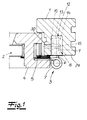
- ausschnittsweise einen Schnitt durch eine gefälzte Gebäudeabschlusstür aus Holz mit einem verstellbaren Türband,
- Fig. 2
- ein Aufnahmeelement mit einem zugeordneten Bandteil des in
Fig. 1 dargestellten Türbandes in einer Explosionsdarstellung, - Fig. 3
- den in
Fig. 2 dargestellten Gegenstand im montierten Zustand, - Fig. 4
- eine Seitendarstellung des in
Fig. 3 dargestellten Gegenstandes, - Fig. 5
- den Schnitt A-A aus
Fig. 4 , - Fig. 6
- die rückseitige Ansicht des in
Fig. 4 dargestellten Gegenstandes, - Fig. 7
- eine Ausführungsvariante des in
Fig. 4 dargestellten Gegenstandes, - Fig. 8
- ausschnittsweise einen Schnitt durch eine gefälzte Gebäudeabschlusstür aus Holz mit einer weiteren Ausführungsvariante des erfindungsgemäßen Türbandes,
- Fig. 9
- ein Aufnahmeelement mit zugeordnetem Bandteil des in
Fig. 8 dargestellten Türbandes in einer Explosionsdarstellung, - Fig. 10
- den Gegenstand der
Fig. 9 im montierten Zustand. - Die in
Fig. 1 dargestellte Gebäudeabschlusstür weist einen Türrahmen 1 aus Holz, einen Türflügel 2 und mindestens zwei Türbänder 3 für den drehbeweglichen Anschluss des Türflügels 2 auf. Der Türflügel 2 weist einen Türflügelrahmen 4 aus einem Holzwerkstoff und eine Türausfachung auf. Die Türausfachung kann beliebig ausgestaltet sein und besteht im Ausführungsbeispiel beispielsweise aus einer Isolierglasscheibenanordnung. Der Türrahmen 1 weist einen türaußenseitigen Falz auf und der Türflügel 2 ist mit einem türinnenseitigen Falz versehen. An der Innenfläche des Falzes des Türflügels 2 ist eine Fugendichtung 5 angeordnet. Im Spaltbereich zwischen dem Türrahmen 1 und dem Türflügel 2 können weitere Dichtungen vorgesehen sein. - Das Türband 3 besteht in seinem grundsätzlichen Aufbau aus zwei drehgelenkig verbundenen Bandteilen 6, 7 und einem Aufnahmeelement 8, wobei eines der Bandteile - im Ausführungsbeispiel das Bandteil 6 - einen in das Aufnahmeelement 8 eingeführten Bandlappen 9 aufweist. Das Aufnahmeelement 8 umfasst gemäß der Darstellung in
Fig. 2 ein Gehäuse 10, zwei in dem Gehäuse 10 drehbar gelagerte Gewindespindeln 11 zur Positionsverstellung des in dem Aufnahmeelement 8 angeordneten Bandlappens 9 sowie eine Klemmeinrichtung 12 mit einer Spannplatte 13 und einer Klemmplatte 14 zur Fixierung des Bandlappens 9. Die Spannplatte 13 ist auf den Gewindespindeln 11 geführt, und die Klemmplatte 14 ist mittels Spannschrauben 15 an der Spannplatte 13 befestigt. - Die Gewindespindeln 11 sind an einem Ende in einer Lagerbohrung 16 des Gehäuses 10 gelagert und an ihrem anderen Ende drehbar in einem Aufnahmeschlitz 17 des Gehäuses 10 gehalten, der sich bis zur Außenkontur des Gehäuses 10 erstreckt. Das Gehäuse 10 ist vorzugsweise einstückig ausgebildet und kann beispielsweise aus einem Druckgussteil, insbesondere einem Metallgussteil, bestehen.
- Die Gewindespindeln 11 weisen an ihrem dem Aufnahmeschlitz 17 zugeordneten Ende jeweils einen Kopf 18 auf, der einen größeren Durchmesser hat als der Spindelschaft und den Rand des Aufnahmeschlitzes 17 überfasst. Bei vergleichender Betrachtung der
Fig. 2 und3 entnimmt man, dass der Kopf 18 der Gewindespindeln 11 drehbeweglich in einer Vertiefung 19 an der Außenfläche des Gehäuses 11 eingepasst ist. Die Vertiefung 19 bildet eine kreisringförmige Stufenfläche 20, die sich in Umfangsrichtung über einen Winkel α von mehr als 180° erstreckt. Dadurch kann der Kopf 18 der Gewindespindel 11 nicht mehr aus dem Aufnahmeschlitz 17 herausrutschen. An das der Lagerbohrung 16 zugeordnete rückwärtige Ende der Gewindespindeln 11 ist jeweils ein Sicherungselement 21 angeschlossen, welches den Rand der Lagerbohrung 16 an der Außenfläche des Gehäuses 10 übergreift. Insbesondere aus der Schnittdarstellung inFig. 5 geht hervor, dass das Sicherungselement 21 aus einem Senkniet besteht, der in eine stirnseitige Bohrung der Gewindespindel 11 eingesetzt und nach der Montage der Gewindespindel 11 umgeformt worden ist. Durch das Sicherungselement 21 auf der einen Seite und den Kopf 18 auf der anderen Seite sind die Gewindespindeln 11 im Gehäuse 10 drehbeweglich und axial fest gelagert. - Aus der Explosionsdarstellung (
Fig. 2 ) in Verbindung mit denFig. 4 bis 6 geht hervor, dass das Gehäuse 10 des Aufnahmeelementes 8 eine Stirnfläche 22 mit einem Schlitz zum Einführen des Bandlappens 9 sowie eine Seitenwand 23 aufweist, und dass in der Seitenwand 23 die Lagerbohrungen 16 und Aufnahmeschlitze 17 zur Lagerung der Gewindespindeln 11 angeordnet sind. Die Aufnahmeschlitze 17 erstrecken sich bis zum rückseitigen Ende 24 der Seitenwand 23. In einem an die Klemmplatte 14 angrenzenden Bereich ist die Seitenwand 23 unterbrochen, wobei der freie Raum so bemessen ist, dass die Klemmplatte 14 hier ihren Platz finden kann (Fig. 6 ). In der Spannplatte 13 ist ferner eine auf den Bandlappen 9 wirkende Stelleineinrichtung 25 angeordnet, die eine Lagekorrektur des Bandlappens 9 innerhalb der Klemmeinrichtung 12 ermöglicht. Die Stelleinrichtung 25 weist einen zwischen der Spannplatte 13 und der Klemmplatte 14 angeordneten Verstellexzenter 26 auf, der an der Spannplatte 13 drehbar gelagert ist und mit der Kontur eines zugeordneten Fensters 27 im Bandlappen 9 zusammenwirkt. Je nach der gewählten Kontur ermöglicht die Stelleinrichtung 25 eine Vertikalverstellung des zwischen Spannplatte 13 und Klemmplatte 14 angeordneten Bandlappens 9 oder eine horizontale Verstellbewegung in Querrichtung zur Wirkungsrichtung der Stellspindeln 11. In dem inFig. 4 dargestellten Ausführungsbeispiel ist die Kontur des Fensters 27 so ausgebildet, dass der Bandlappen 9 mittels einer Drehbewegung des Verstellexzenters 26 vertikal verstellbar ist. InFig. 7 ist die Kontur des Fensters 27 so gewählt, dass der Bandlappen 9 mittels einer Drehbewegung des Verstellexzenters 26 in Einschubrichtung horizontal verstellt werden kann. - In der Seitenwand 23 des Gehäuses 10 des Aufnahmeelementes 8 sind Öffnungen zur Betätigung der beschriebenen Funktionselemente angeordnet. Die Ausfräsung für den Einbau des Aufnahmeelementes 8 befindet sich auf der Innenseite der Tür in einer Spiegelfläche 29 des Türrahmens 1, die bei geschlossener Tür parallel zum Türflügel 2 verläuft. Mittels einer Fräs- und Bohrschablone werden in der Laibung des Türrahmens 1 Bohrungen 30 eingebracht, die mit den Öffnungen 28 im Aufnahmegehäuse 8 des Türbandes fluchten (
Fig. 1 ). - Die
Fig. 8 bis 10 zeigen eine Ausführungsvariante des erfindungsgemäßen Türbandes, dessen Aufnahmeelement 8' an der Schmalseite des Türflügels 2 montiert wird. Die Einbausituation ist inFig. 8 dargestellt. Das Aufnahmeelement 8' umfasst ebenfalls ein Gehäuse 10' sowie zwei in dem Gehäuse 10' drehbar gelagerte Stellspindeln 11 zur Positionsverstellung des in dem Aufnahmeelement 8' angeordneten Bandlappens 9', wobei die Gewindespindeln 11 ebenfalls an einem Ende in einer Lagerbohrung 16 des Gehäuses 10' gelagert und an ihrem anderen Ende drehbar in einem Aufnahmeschlitz 17 des Gehäuses 10' gehalten sind, der sich bis zur Außenkontur des Gehäuses 10' erstreckt. Das Gehäuse 10' des Aufnahmeelementes 8' ist vorzugsweise einstückig, z. B. als metallisches Druckgussteil, ausgebildet und weist eine an einer Längsseite offene Aufnahmetasche 32 für den Bandlappen 9' auf. Die Aufnahmeschlitze 17 des an der Schmalseite eines Türflügels 2 anschraubbaren Gehäuses 10' sind an der im montierten Zustand sichtbaren Fläche 31 des Gehäuses 10' angeordnet und erstrecken sich bis zu dem die Aufnahmetasche 32 begrenzenden Längsrand. Der dem Aufnahmeelement 8' zugeordnete Bandlappen 9' ist als Winkelblech ausgebildet, welches einen in das Aufnahmeelement 8' eingeführten Abschnitt sowie einen mit einem Gelenkteil 37 verbundenen Verbindungsabschnitt 36 aufweist. Der in das Aufnahmeelement 8' eingeführte Abschnitt ist unmittelbar mit den Gewindespindeln 11 verbunden. Die Gewindespindeln 11 greifen in Gewindebohrungen des Bandlappens 9' ein. Durch eine Drehbetätigung der Gewindespindeln 11 ist eine Seitenverstellung des Türflügels 2 relativ zum Türrahmen 1 möglich. - Aus einer vergleichenden Betrachtung der
Fig. 9 und10 wird deutlich, dass die Gewindespindeln 11 an ihrem dem Aufnahmeschlitz 17 zugeordneten Ende einen Kopf 18 aufweisen, der einen größeren Durchmesser hat als der Spindelschaft und den Rand des Aufnahmeschlitzes 17 überfasst. Im montierten Zustand ist der Kopf 18 der Gewindespindel 11 drehbeweglich in einer Vertiefung 19 an der Außenfläche des Gehäuses 10' eingepasst. DerFig. 9 entnimmt man, dass die Vertiefung 19 eine kreisringförmige Stufenfläche 20 bildet, die sich in Umfangsrichtung über einen Winkel α von mehr als 180° erstreckt. Diese Anordnung verhindert, dass der Kopf 18 der Gewindespindel 11 in der inFig. 10 dargestellten Einbausituation aus dem Aufnahmeschlitz 17 des Gehäuses 10' herausrutschen kann. An ihrem rückseitigen Ende sind die Gewindespindeln 11 in der schon beschriebenen Weise z. B. mittels eines Senkniets in Lagerbohrungen 16 des Gehäuses 10' axial fest gehalten. - Den
Fig. 9 und10 entnimmt man, dass der die Aufnahmetasche 32 begrenzende Rand an der im montierten Zustand sichtbaren Fläche 31 des Gehäuses 10' durch einen Steg 33 verstärkt ist und dass der Steg 33 Öffnungen 34 enthält, um die in dem Bandlappen 9' vormontierten Gewindespindeln 11 einführen zu können. Bei einer vergleichenden Betrachtung derFig. 9 und10 wird auch deutlich, dass das Gehäuse 10' Führungsvorsprünge 35 aufweist, die den Verbindungsabschnitt 36 des Bandlappens 9' an seinen beiden Rändern stützen und Vertikalkräfte quer zur Achsrichtung der Gewindespindeln 11 aufnehmen. Die Gewindespindeln 11 und deren Lagerungen werden hierdurch kräftemäßig entlastet. Es ist auch sichergestellt, dass der Bandlappen 9' unter dem Gewicht des angehängten Türflügels 2 nicht nach unten absacken kann.
Claims (17)
- Türband, insbesondere für gefälzte Gebäudeabschlusstüren aus Holz, mit zwei drehgelenkig verbundenen Bandteilen (6, 7) und einem Aufnahmeelement (8, 8'), wobei eines der Bandteile (6) einen in das Aufnahmeelement (8, 8') eingeführten Bandlappen (9, 9') aufweist und wobei das Aufnahmeelement (8, 8') ein Gehäuse (10, 10') sowie zwei in dem Gehäuse (10, 10') drehbar gelagerte Gewindespindeln (11) zur Positionsverstellung des in dem Aufnahmeelement (8, 8') angeordneten Bandlappens (9, 9') umfasst, dadurch gekennzeichnet, dass die Gewindespindeln (11) jeweils an einem Ende in einer Lagerbohrung (16) des Gehäuses (10, 10') gelagert und an ihrem anderen Ende drehbar in einem Aufnahmeschlitz (17) des Gehäuses (10, 10') gehalten sind, der sich bis zur Außenkontur des Gehäuses (10, 10') erstreckt.
- Türband nach Anspruch 1, dadurch gekennzeichnet, dass das Gehäuse (10, 10') des Aufnahmeelements (8, 8') einstückig ausgebildet ist.
- Türband nach Anspruch 1 oder 2, dadurch gekennzeichnet, dass die Gewindespindeln (11) an ihrem dem Aufnahmeschlitz (17) zugeordneten Ende einen Kopf (18) aufweisen, der einen größeren Durchmesser hat als der Spindelschaft und den Rand des Aufnahmeschlitzes (17) überfasst.
- Türband nach Anspruch 3, dadurch gekennzeichnet, dass der Kopf (18) der Gewindespindeln (11) drehbeweglich in eine Vertiefung (19) an der Außenfläche des Gehäuses (10, 10') eingepasst ist, wobei die Vertiefung (19) eine kreisringförmige Stufenfläche (20) bildet, die sich in Umfangsrichtung über einen Winkel (α) von mehr als 180° erstreckt.
- Türband nach einem der Ansprüche 1 bis 4, dadurch gekennzeichnet, dass an das der Lagerbohrung (16) zugeordnete Ende der Gewindespindeln (11) ein Sicherungselement (21) angeschlossen ist, welches den Rand der Lagerbohrung (16) an der Außenfläche des Gehäuses (10, 10') übergreift.
- Türband nach Anspruch 5, dadurch gekennzeichnet, dass das Sicherungselement (21) aus einem Senkniet besteht, der in eine stirnseitige Bohrung der Gewindespindel (11) eingesetzt und nach der Montage der Gewindespindel (11) umgeformt worden ist.
- Türband nach einem der Ansprüche 1 bis 6, dadurch gekennzeichnet, dass die Gewindespindeln (11) in Gewindebohrungen des Bandlappens (9') eingreifen.
- Türband nach Anspruch 7, dadurch gekennzeichnet, dass das Gehäuse (10') des Aufnahmeelementes (8') eine an einer Gehäuselängsseite offene Aufnahmetasche (32) für den Bandlappen (9') aufweist und an der Schmalseite eines Türflügels (2) anschraubbar ist und dass die Aufnahmeschlitze (17) an der im montierten Zustand sichtbaren Fläche (31) des Gehäuses (10') angeordnet sind und sich bis zu dem die Aufnahmetasche (32) begrenzenden Längsrand erstrecken.
- Türband nach Anspruch 8, dadurch gekennzeichnet, dass der die Aufnahmetasche (32) begrenzende Rand an der im montierten Zustand sichtbaren Fläche (31) des Gehäuses (10') durch einen Steg (33) verstärkt ist und dass der Steg (33) Öffnungen (34) enthält, um die in dem Bandlappen (9') vormontierten Gewindespindeln (11) einführen zu können.
- Türband nach einem der Ansprüche 7 bis 9, dadurch gekennzeichnet, dass der dem Aufnahmeelement (8') zugeordnete Bandlappen (9') als Winkelblech ausgebildet ist, welches einen in das Aufnahmeelement (8) eingeführten Abschnitt sowie einen mit einem Gelenkteil (37) verbundenen Verbindungsabschnitt (36) aufweist, und dass das Gehäuse (10') Führungsvorsprünge (35) aufweist, die den Verbindungsabschnitt (36) an seinen beiden Rändern stützen und Vertikalkräfte quer zur Achsrichtung der Gewindespindeln (11) aufnehmen.
- Türband nach einem der Ansprüche 1 bis 6, dadurch gekennzeichnet, dass das Aufnahmeelement (8) eine Klemmeinrichtung (12) mit einer Spannplatte (13) und einer Klemmplatte (14) zur Fixierung des Bandlappens (9) aufweist, wobei die Spannplatte (13) auf den Gewindespindeln (11) geführt ist und wobei die Klemmplatte (14) mittels Spannschrauben (15) an der Spannplatte (13) befestigt ist.
- Türband nach Anspruch 11, dadurch gekennzeichnet, dass das Gehäuse (10) des Aufnahmeelementes (8) eine Stirnfläche (22) mit einem Schlitz zum Einführen des Bandlappens (9) und eine Seitenwand (23) aufweist und dass in der Seitenwand (23) die Lagerbohrungen (16) und Aufnahmeschlitze (17) zur Lagerung der Gewindespindeln (11) angeordnet sind, wobei die Aufnahmeschlitze (17) sich bis zum rückseitigen Ende (24) der Seitenwand (23) erstrecken.
- Türband nach Anspruch 12, dadurch gekennzeichnet, dass die Seitenwand (23) in einem an die Klemmplatte (14) angrenzenden Bereich unterbrochen ist, wobei der freie Raum so bemessen ist, dass die Klemmplatte (14) hierin Platz findet.
- Türband nach einem der Ansprüche 11 bis 13, dadurch gekennzeichnet, dass an der Spannplatte (13) eine auf den Bandlappen (9) wirkende Stelleinrichtung (25) angeordnet ist, die eine Lagekorrektur des Bandlappens (9) innerhalb der Klemmeinrichtung (12) ermöglicht.
- Türband nach Anspruch 14, dadurch gekennzeichnet, dass zwischen der Spannplatte (13) und der Klemmplatte (14) ein Verstellexzenter (26) angeordnet ist, der an der Spannplatte (13) drehbar gelagert ist und mit der Kontur eines zugeordneten Fensters (27) im Bandlappen (9) zusammenwirkt.
- Türband nach Anspruch 15, dadurch gekennzeichnet, dass die Kontur des Fensters (27) so ausgebildet ist, dass der Bandlappen (9) mittels einer Drehbewegung des Verstellexzenters (26) in Einschubrichtung horizontal verstellbar ist.
- Türband nach Anspruch 15, dadurch gekennzeichnet, dass die Kontur des Fensters (27) so ausgebildet ist, dass der Bandlappen (9) mittels einer Drehbewegung des Verstellexzenters (26) vertikal verstellbar ist.
Priority Applications (1)
| Application Number | Priority Date | Filing Date | Title |
|---|---|---|---|
| PL11152019T PL2369108T3 (pl) | 2010-03-23 | 2011-01-25 | Zawiasa drzwiowa w szczególności dla przylgowych, drewnianych drzwi wejściowych do budynku |
Applications Claiming Priority (1)
| Application Number | Priority Date | Filing Date | Title |
|---|---|---|---|
| DE102010012576A DE102010012576B3 (de) | 2010-03-23 | 2010-03-23 | Türband, insbesondere für gefälzte Gebäudeabschlusstüren aus Holz |
Publications (3)
| Publication Number | Publication Date |
|---|---|
| EP2369108A2 true EP2369108A2 (de) | 2011-09-28 |
| EP2369108A3 EP2369108A3 (de) | 2013-04-17 |
| EP2369108B1 EP2369108B1 (de) | 2014-12-31 |
Family
ID=43536379
Family Applications (1)
| Application Number | Title | Priority Date | Filing Date |
|---|---|---|---|
| EP11152019.3A Not-in-force EP2369108B1 (de) | 2010-03-23 | 2011-01-25 | Türband, insbesondere für gefälzte Gebäudeabschlusstüren aus Holz |
Country Status (4)
| Country | Link |
|---|---|
| EP (1) | EP2369108B1 (de) |
| DE (1) | DE102010012576B3 (de) |
| PL (1) | PL2369108T3 (de) |
| RU (1) | RU2469165C1 (de) |
Families Citing this family (2)
| Publication number | Priority date | Publication date | Assignee | Title |
|---|---|---|---|---|
| DE202014100994U1 (de) * | 2014-03-06 | 2015-06-09 | Breuer & Schmitz Gmbh & Co. Kg | Bandtasche zum Befestigen eines Türbandes |
| DE102019128245B3 (de) * | 2019-10-18 | 2020-10-08 | Dr. Hahn Gmbh & Co. Kg | Band zur Befestigung eines Flügels an einem Rahmen sowie Anordnung mit einem Hohlprofil und mit diesem Band |
Citations (1)
| Publication number | Priority date | Publication date | Assignee | Title |
|---|---|---|---|---|
| DE102004042923B3 (de) | 2004-09-02 | 2005-08-11 | Simonswerk, Gmbh | Bandtasche zur Befestigung eines Türbandes |
Family Cites Families (11)
| Publication number | Priority date | Publication date | Assignee | Title |
|---|---|---|---|---|
| DE7736524U1 (de) * | 1977-11-30 | 1978-03-02 | Oni-Metallwarenfabriken Guenter & Co, 4973 Vlotho | Klappenscharnier |
| DE3932733C2 (de) * | 1989-09-30 | 1997-04-30 | Simonswerk Gmbh | Bandaufnahmeelement für Block- und Futterzargen aus Holz |
| DE4307067C2 (de) * | 1993-03-06 | 1995-03-09 | Heine & Sohn Anuba Beschlaege | Tür- oder Fensterband |
| US5799370A (en) * | 1996-06-12 | 1998-09-01 | The Stanley Works | Adjustable hinge |
| DE20210049U1 (de) * | 2002-06-29 | 2003-02-20 | Bartels Systembeschlaege Gmbh | Bandaufnahmeelement für Block- und Futterzargen |
| DE10336750A1 (de) * | 2003-08-08 | 2005-03-10 | Eco Schulte Gmbh & Co | Befestigungsvorrichtung für eine Bandaufnahme |
| DE10356403B3 (de) * | 2003-12-03 | 2004-10-28 | Simonswerk, Gmbh | Mehrdimensional verstellbares Türband |
| SE529137C2 (sv) * | 2005-06-15 | 2007-05-08 | Assa Ab | Insticksgångjärn |
| DE102005036212B3 (de) * | 2005-08-02 | 2006-09-07 | Simonswerk, Gmbh | Bandaufnahmeelement für Zargenhohlprofile |
| CN101315010A (zh) * | 2008-06-06 | 2008-12-03 | 安徽富煌钢构股份有限公司 | 可调节三叉式合页 |
| DE102008036151A1 (de) * | 2008-08-01 | 2010-02-04 | Glutz Deutschland Gmbh | Scharnierband mit einer Unterkonstruktion zur Befestigung an einem Türblatt |
-
2010
- 2010-03-23 DE DE102010012576A patent/DE102010012576B3/de not_active Expired - Fee Related
-
2011
- 2011-01-25 PL PL11152019T patent/PL2369108T3/pl unknown
- 2011-01-25 EP EP11152019.3A patent/EP2369108B1/de not_active Not-in-force
- 2011-03-22 RU RU2011110870/12A patent/RU2469165C1/ru not_active IP Right Cessation
Patent Citations (1)
| Publication number | Priority date | Publication date | Assignee | Title |
|---|---|---|---|---|
| DE102004042923B3 (de) | 2004-09-02 | 2005-08-11 | Simonswerk, Gmbh | Bandtasche zur Befestigung eines Türbandes |
Also Published As
| Publication number | Publication date |
|---|---|
| RU2469165C1 (ru) | 2012-12-10 |
| DE102010012576B3 (de) | 2011-03-10 |
| PL2369108T3 (pl) | 2015-06-30 |
| RU2011110870A (ru) | 2012-09-27 |
| EP2369108A3 (de) | 2013-04-17 |
| EP2369108B1 (de) | 2014-12-31 |
Similar Documents
| Publication | Publication Date | Title |
|---|---|---|
| EP1861574B1 (de) | Rahmenlose glastüre | |
| EP2369109B1 (de) | Türband für gefälzte Gebäudeabschlusstüren aus Holz | |
| WO2008135071A1 (de) | Bauelement zum herstellen eines sektionaltorblatts und stirnkappe dafür | |
| EP2476836B1 (de) | Türband | |
| EP3680430B1 (de) | Gebäudetür | |
| EP2754813B1 (de) | Band, insbesondere für Kunststoff-Türen und -Fenster | |
| EP0497107A1 (de) | Flügelrahmenseitige Ecklagerbaugruppe | |
| EP2369108B1 (de) | Türband, insbesondere für gefälzte Gebäudeabschlusstüren aus Holz | |
| EP0844348B1 (de) | Band für Türen oder Fenster | |
| EP1215357A2 (de) | Bandanordnung für Türen, Fenster und dergleichen | |
| DE19719113C2 (de) | Türsystem | |
| DE102008036151A1 (de) | Scharnierband mit einer Unterkonstruktion zur Befestigung an einem Türblatt | |
| DE60010806T2 (de) | Verdeckter Öffnungsbeschlag für Drehflügeltür oder -Fenster | |
| EP2072744B1 (de) | Zargenprofil für eine Hebe-Schiebetür | |
| EP1813754B1 (de) | Obertürschliesser | |
| DE60210362T2 (de) | Gelenkbeschlag für Flügel einer Tür oder eines Dreh- und/oder Drehkippfensters | |
| DE202004011157U1 (de) | Vorsatzschale zur Wärmeisolation eines Fensters oder einer Tür | |
| CH655762A5 (en) | Folding sliding part for external and internal walls of buildings | |
| DE102009017029B3 (de) | Bandaufnahme für Stahlzargen | |
| EP3461982B1 (de) | Türanordnung | |
| DE2932865A1 (de) | Beschlag fuer dachfenster | |
| DE102017202727B4 (de) | Verdeckt angeordneter Beschlag für Fenster, Türen oder dergleichen | |
| AT204439B (de) | Verschlußanordnung für Fenster od. dgl. | |
| EP3449078B1 (de) | Sortiment zur montage von sektionaltoren | |
| DE202007011394U1 (de) | Fenster oder Tür und Bauteilsatz eines Riegelteils für ein Fenster oder eine Tür |
Legal Events
| Date | Code | Title | Description |
|---|---|---|---|
| PUAI | Public reference made under article 153(3) epc to a published international application that has entered the european phase |
Free format text: ORIGINAL CODE: 0009012 |
|
| AK | Designated contracting states |
Kind code of ref document: A2 Designated state(s): AL AT BE BG CH CY CZ DE DK EE ES FI FR GB GR HR HU IE IS IT LI LT LU LV MC MK MT NL NO PL PT RO RS SE SI SK SM TR |
|
| AX | Request for extension of the european patent |
Extension state: BA ME |
|
| PUAL | Search report despatched |
Free format text: ORIGINAL CODE: 0009013 |
|
| AK | Designated contracting states |
Kind code of ref document: A3 Designated state(s): AL AT BE BG CH CY CZ DE DK EE ES FI FR GB GR HR HU IE IS IT LI LT LU LV MC MK MT NL NO PL PT RO RS SE SI SK SM TR |
|
| AX | Request for extension of the european patent |
Extension state: BA ME |
|
| RIC1 | Information provided on ipc code assigned before grant |
Ipc: E05D 7/04 20060101AFI20130313BHEP |
|
| 17P | Request for examination filed |
Effective date: 20130531 |
|
| RBV | Designated contracting states (corrected) |
Designated state(s): AL AT BE BG CH CY CZ DE DK EE ES FI FR GB GR HR HU IE IS IT LI LT LU LV MC MK MT NL NO PL PT RO RS SE SI SK SM TR |
|
| GRAP | Despatch of communication of intention to grant a patent |
Free format text: ORIGINAL CODE: EPIDOSNIGR1 |
|
| INTG | Intention to grant announced |
Effective date: 20140714 |
|
| GRAS | Grant fee paid |
Free format text: ORIGINAL CODE: EPIDOSNIGR3 |
|
| GRAA | (expected) grant |
Free format text: ORIGINAL CODE: 0009210 |
|
| AK | Designated contracting states |
Kind code of ref document: B1 Designated state(s): AL AT BE BG CH CY CZ DE DK EE ES FI FR GB GR HR HU IE IS IT LI LT LU LV MC MK MT NL NO PL PT RO RS SE SI SK SM TR |
|
| REG | Reference to a national code |
Ref country code: CH Ref legal event code: EP Ref country code: GB Ref legal event code: FG4D Free format text: NOT ENGLISH |
|
| REG | Reference to a national code |
Ref country code: IE Ref legal event code: FG4D Free format text: LANGUAGE OF EP DOCUMENT: GERMAN |
|
| REG | Reference to a national code |
Ref country code: DE Ref legal event code: R096 Ref document number: 502011005442 Country of ref document: DE Effective date: 20150212 |
|
| REG | Reference to a national code |
Ref country code: AT Ref legal event code: REF Ref document number: 704527 Country of ref document: AT Kind code of ref document: T Effective date: 20150215 |
|
| REG | Reference to a national code |
Ref country code: CH Ref legal event code: NV Representative=s name: KELLER AND PARTNER PATENTANWAELTE AG, CH |
|
| REG | Reference to a national code |
Ref country code: CH Ref legal event code: PCAR Free format text: NEW ADDRESS: EIGERSTRASSE 2 POSTFACH, 3000 BERN 14 (CH) |
|
| PG25 | Lapsed in a contracting state [announced via postgrant information from national office to epo] |
Ref country code: LT Free format text: LAPSE BECAUSE OF FAILURE TO SUBMIT A TRANSLATION OF THE DESCRIPTION OR TO PAY THE FEE WITHIN THE PRESCRIBED TIME-LIMIT Effective date: 20141231 Ref country code: NO Free format text: LAPSE BECAUSE OF FAILURE TO SUBMIT A TRANSLATION OF THE DESCRIPTION OR TO PAY THE FEE WITHIN THE PRESCRIBED TIME-LIMIT Effective date: 20150331 Ref country code: FI Free format text: LAPSE BECAUSE OF FAILURE TO SUBMIT A TRANSLATION OF THE DESCRIPTION OR TO PAY THE FEE WITHIN THE PRESCRIBED TIME-LIMIT Effective date: 20141231 |
|
| REG | Reference to a national code |
Ref country code: NL Ref legal event code: VDEP Effective date: 20141231 |
|
| REG | Reference to a national code |
Ref country code: LT Ref legal event code: MG4D |
|
| PG25 | Lapsed in a contracting state [announced via postgrant information from national office to epo] |
Ref country code: LV Free format text: LAPSE BECAUSE OF FAILURE TO SUBMIT A TRANSLATION OF THE DESCRIPTION OR TO PAY THE FEE WITHIN THE PRESCRIBED TIME-LIMIT Effective date: 20141231 Ref country code: RS Free format text: LAPSE BECAUSE OF FAILURE TO SUBMIT A TRANSLATION OF THE DESCRIPTION OR TO PAY THE FEE WITHIN THE PRESCRIBED TIME-LIMIT Effective date: 20141231 Ref country code: GR Free format text: LAPSE BECAUSE OF FAILURE TO SUBMIT A TRANSLATION OF THE DESCRIPTION OR TO PAY THE FEE WITHIN THE PRESCRIBED TIME-LIMIT Effective date: 20150401 Ref country code: HR Free format text: LAPSE BECAUSE OF FAILURE TO SUBMIT A TRANSLATION OF THE DESCRIPTION OR TO PAY THE FEE WITHIN THE PRESCRIBED TIME-LIMIT Effective date: 20141231 Ref country code: SE Free format text: LAPSE BECAUSE OF FAILURE TO SUBMIT A TRANSLATION OF THE DESCRIPTION OR TO PAY THE FEE WITHIN THE PRESCRIBED TIME-LIMIT Effective date: 20141231 |
|
| PG25 | Lapsed in a contracting state [announced via postgrant information from national office to epo] |
Ref country code: NL Free format text: LAPSE BECAUSE OF FAILURE TO SUBMIT A TRANSLATION OF THE DESCRIPTION OR TO PAY THE FEE WITHIN THE PRESCRIBED TIME-LIMIT Effective date: 20141231 |
|
| REG | Reference to a national code |
Ref country code: PL Ref legal event code: T3 |
|
| PG25 | Lapsed in a contracting state [announced via postgrant information from national office to epo] |
Ref country code: SK Free format text: LAPSE BECAUSE OF FAILURE TO SUBMIT A TRANSLATION OF THE DESCRIPTION OR TO PAY THE FEE WITHIN THE PRESCRIBED TIME-LIMIT Effective date: 20141231 Ref country code: RO Free format text: LAPSE BECAUSE OF FAILURE TO SUBMIT A TRANSLATION OF THE DESCRIPTION OR TO PAY THE FEE WITHIN THE PRESCRIBED TIME-LIMIT Effective date: 20141231 Ref country code: ES Free format text: LAPSE BECAUSE OF FAILURE TO SUBMIT A TRANSLATION OF THE DESCRIPTION OR TO PAY THE FEE WITHIN THE PRESCRIBED TIME-LIMIT Effective date: 20141231 |
|
| PG25 | Lapsed in a contracting state [announced via postgrant information from national office to epo] |
Ref country code: LU Free format text: LAPSE BECAUSE OF FAILURE TO SUBMIT A TRANSLATION OF THE DESCRIPTION OR TO PAY THE FEE WITHIN THE PRESCRIBED TIME-LIMIT Effective date: 20150125 Ref country code: IS Free format text: LAPSE BECAUSE OF FAILURE TO SUBMIT A TRANSLATION OF THE DESCRIPTION OR TO PAY THE FEE WITHIN THE PRESCRIBED TIME-LIMIT Effective date: 20150430 |
|
| REG | Reference to a national code |
Ref country code: DE Ref legal event code: R097 Ref document number: 502011005442 Country of ref document: DE |
|
| PG25 | Lapsed in a contracting state [announced via postgrant information from national office to epo] |
Ref country code: DK Free format text: LAPSE BECAUSE OF FAILURE TO SUBMIT A TRANSLATION OF THE DESCRIPTION OR TO PAY THE FEE WITHIN THE PRESCRIBED TIME-LIMIT Effective date: 20141231 Ref country code: MC Free format text: LAPSE BECAUSE OF FAILURE TO SUBMIT A TRANSLATION OF THE DESCRIPTION OR TO PAY THE FEE WITHIN THE PRESCRIBED TIME-LIMIT Effective date: 20141231 Ref country code: EE Free format text: LAPSE BECAUSE OF FAILURE TO SUBMIT A TRANSLATION OF THE DESCRIPTION OR TO PAY THE FEE WITHIN THE PRESCRIBED TIME-LIMIT Effective date: 20141231 |
|
| REG | Reference to a national code |
Ref country code: IE Ref legal event code: MM4A |
|
| PLBE | No opposition filed within time limit |
Free format text: ORIGINAL CODE: 0009261 |
|
| STAA | Information on the status of an ep patent application or granted ep patent |
Free format text: STATUS: NO OPPOSITION FILED WITHIN TIME LIMIT |
|
| 26N | No opposition filed |
Effective date: 20151001 |
|
| REG | Reference to a national code |
Ref country code: FR Ref legal event code: ST Effective date: 20151116 |
|
| PG25 | Lapsed in a contracting state [announced via postgrant information from national office to epo] |
Ref country code: IE Free format text: LAPSE BECAUSE OF NON-PAYMENT OF DUE FEES Effective date: 20150125 |
|
| PG25 | Lapsed in a contracting state [announced via postgrant information from national office to epo] |
Ref country code: FR Free format text: LAPSE BECAUSE OF NON-PAYMENT OF DUE FEES Effective date: 20150302 Ref country code: SI Free format text: LAPSE BECAUSE OF FAILURE TO SUBMIT A TRANSLATION OF THE DESCRIPTION OR TO PAY THE FEE WITHIN THE PRESCRIBED TIME-LIMIT Effective date: 20141231 |
|
| PG25 | Lapsed in a contracting state [announced via postgrant information from national office to epo] |
Ref country code: MT Free format text: LAPSE BECAUSE OF FAILURE TO SUBMIT A TRANSLATION OF THE DESCRIPTION OR TO PAY THE FEE WITHIN THE PRESCRIBED TIME-LIMIT Effective date: 20141231 |
|
| PG25 | Lapsed in a contracting state [announced via postgrant information from national office to epo] |
Ref country code: BG Free format text: LAPSE BECAUSE OF FAILURE TO SUBMIT A TRANSLATION OF THE DESCRIPTION OR TO PAY THE FEE WITHIN THE PRESCRIBED TIME-LIMIT Effective date: 20141231 Ref country code: HU Free format text: LAPSE BECAUSE OF FAILURE TO SUBMIT A TRANSLATION OF THE DESCRIPTION OR TO PAY THE FEE WITHIN THE PRESCRIBED TIME-LIMIT; INVALID AB INITIO Effective date: 20110125 Ref country code: SM Free format text: LAPSE BECAUSE OF FAILURE TO SUBMIT A TRANSLATION OF THE DESCRIPTION OR TO PAY THE FEE WITHIN THE PRESCRIBED TIME-LIMIT Effective date: 20141231 |
|
| PG25 | Lapsed in a contracting state [announced via postgrant information from national office to epo] |
Ref country code: CY Free format text: LAPSE BECAUSE OF FAILURE TO SUBMIT A TRANSLATION OF THE DESCRIPTION OR TO PAY THE FEE WITHIN THE PRESCRIBED TIME-LIMIT Effective date: 20141231 |
|
| PG25 | Lapsed in a contracting state [announced via postgrant information from national office to epo] |
Ref country code: PT Free format text: LAPSE BECAUSE OF FAILURE TO SUBMIT A TRANSLATION OF THE DESCRIPTION OR TO PAY THE FEE WITHIN THE PRESCRIBED TIME-LIMIT Effective date: 20150501 Ref country code: BE Free format text: LAPSE BECAUSE OF NON-PAYMENT OF DUE FEES Effective date: 20150131 |
|
| PG25 | Lapsed in a contracting state [announced via postgrant information from national office to epo] |
Ref country code: TR Free format text: LAPSE BECAUSE OF FAILURE TO SUBMIT A TRANSLATION OF THE DESCRIPTION OR TO PAY THE FEE WITHIN THE PRESCRIBED TIME-LIMIT Effective date: 20141231 |
|
| PGFP | Annual fee paid to national office [announced via postgrant information from national office to epo] |
Ref country code: GB Payment date: 20180119 Year of fee payment: 8 |
|
| PG25 | Lapsed in a contracting state [announced via postgrant information from national office to epo] |
Ref country code: MK Free format text: LAPSE BECAUSE OF FAILURE TO SUBMIT A TRANSLATION OF THE DESCRIPTION OR TO PAY THE FEE WITHIN THE PRESCRIBED TIME-LIMIT Effective date: 20141231 |
|
| PG25 | Lapsed in a contracting state [announced via postgrant information from national office to epo] |
Ref country code: AL Free format text: LAPSE BECAUSE OF FAILURE TO SUBMIT A TRANSLATION OF THE DESCRIPTION OR TO PAY THE FEE WITHIN THE PRESCRIBED TIME-LIMIT Effective date: 20141231 |
|
| GBPC | Gb: european patent ceased through non-payment of renewal fee |
Effective date: 20190125 |
|
| PG25 | Lapsed in a contracting state [announced via postgrant information from national office to epo] |
Ref country code: GB Free format text: LAPSE BECAUSE OF NON-PAYMENT OF DUE FEES Effective date: 20190125 |
|
| REG | Reference to a national code |
Ref country code: CH Ref legal event code: PFA Owner name: SIMONSWERK, GESELLSCHAFT MIT BESCHRAENKTER HAF, DE Free format text: FORMER OWNER: SIMONSWERK, GESELLSCHAFT MIT BESCHRAENKTER HAFTUNG, DE |
|
| PGFP | Annual fee paid to national office [announced via postgrant information from national office to epo] |
Ref country code: CH Payment date: 20210120 Year of fee payment: 11 Ref country code: CZ Payment date: 20210122 Year of fee payment: 11 Ref country code: IT Payment date: 20210121 Year of fee payment: 11 |
|
| PGFP | Annual fee paid to national office [announced via postgrant information from national office to epo] |
Ref country code: DE Payment date: 20210129 Year of fee payment: 11 Ref country code: PL Payment date: 20210115 Year of fee payment: 11 Ref country code: AT Payment date: 20210121 Year of fee payment: 11 |
|
| REG | Reference to a national code |
Ref country code: DE Ref legal event code: R119 Ref document number: 502011005442 Country of ref document: DE |
|
| REG | Reference to a national code |
Ref country code: CH Ref legal event code: PL |
|
| REG | Reference to a national code |
Ref country code: AT Ref legal event code: MM01 Ref document number: 704527 Country of ref document: AT Kind code of ref document: T Effective date: 20220125 |
|
| PG25 | Lapsed in a contracting state [announced via postgrant information from national office to epo] |
Ref country code: DE Free format text: LAPSE BECAUSE OF NON-PAYMENT OF DUE FEES Effective date: 20220802 Ref country code: CZ Free format text: LAPSE BECAUSE OF NON-PAYMENT OF DUE FEES Effective date: 20220125 Ref country code: AT Free format text: LAPSE BECAUSE OF NON-PAYMENT OF DUE FEES Effective date: 20220125 |
|
| PG25 | Lapsed in a contracting state [announced via postgrant information from national office to epo] |
Ref country code: LI Free format text: LAPSE BECAUSE OF NON-PAYMENT OF DUE FEES Effective date: 20220131 Ref country code: CH Free format text: LAPSE BECAUSE OF NON-PAYMENT OF DUE FEES Effective date: 20220131 |
|
| PG25 | Lapsed in a contracting state [announced via postgrant information from national office to epo] |
Ref country code: IT Free format text: LAPSE BECAUSE OF NON-PAYMENT OF DUE FEES Effective date: 20220125 |
|
| PG25 | Lapsed in a contracting state [announced via postgrant information from national office to epo] |
Ref country code: PL Free format text: LAPSE BECAUSE OF NON-PAYMENT OF DUE FEES Effective date: 20220125 |