EP2368803A2 - Etikettiermaschine zur Verarbeitung von Rollenmaterial und Vorrichtung zur Aufnahme von Rollenmaterial - Google Patents
Etikettiermaschine zur Verarbeitung von Rollenmaterial und Vorrichtung zur Aufnahme von Rollenmaterial Download PDFInfo
- Publication number
- EP2368803A2 EP2368803A2 EP11155394A EP11155394A EP2368803A2 EP 2368803 A2 EP2368803 A2 EP 2368803A2 EP 11155394 A EP11155394 A EP 11155394A EP 11155394 A EP11155394 A EP 11155394A EP 2368803 A2 EP2368803 A2 EP 2368803A2
- Authority
- EP
- European Patent Office
- Prior art keywords
- plate
- roll material
- labeling machine
- safety device
- plane
- Prior art date
- Legal status (The legal status is an assumption and is not a legal conclusion. Google has not performed a legal analysis and makes no representation as to the accuracy of the status listed.)
- Granted
Links
Images



Classifications
-
- B—PERFORMING OPERATIONS; TRANSPORTING
- B65—CONVEYING; PACKING; STORING; HANDLING THIN OR FILAMENTARY MATERIAL
- B65C—LABELLING OR TAGGING MACHINES, APPARATUS, OR PROCESSES
- B65C9/00—Details of labelling machines or apparatus
- B65C9/08—Label feeding
- B65C9/18—Label feeding from strips, e.g. from rolls
- B65C9/1892—Spools or cassettes for strips
-
- B—PERFORMING OPERATIONS; TRANSPORTING
- B65—CONVEYING; PACKING; STORING; HANDLING THIN OR FILAMENTARY MATERIAL
- B65C—LABELLING OR TAGGING MACHINES, APPARATUS, OR PROCESSES
- B65C9/00—Details of labelling machines or apparatus
- B65C9/08—Label feeding
- B65C9/18—Label feeding from strips, e.g. from rolls
Definitions
- the present invention relates to a labeling machine for processing roll material with at least one rotatably mounted plate.
- the invention relates to a device for receiving roll material.
- the roll material lies with a front side on a plate.
- labeling There are two ways to carry out the labeling, which is mostly used for cans, PET bottles or glass bottles. On the one hand, labeling with pre-cut labels from one magazine and, on the other hand, labeling with labels can take place from the roll. In order to reduce the expenditure on personnel, for example for changing the labeling blank magazines, the second option has become more and more popular.
- the label to be applied to the article is produced by cutting pieces of an endless label tape just before labeling.
- the cutting process is carried out in such a way that are mounted on the vacuum roller knives, which are guided past a rigid counter knife on which the cut is made. Subsequently, the produced individual label is transferred to the gripping cylinder, which is at the gluing station passes and provides a glue pattern.
- the object to be labeled is guided past the gripping cylinder for label application, wherein a single label is completely wound by rotating the article on its circumference. After winding, the end of the label overlaps the beginning of the label and is glued to it.
- a labeling machine as described above, is in the German Utility Model DE 20 2005 002 793 U1 disclosed.
- the disadvantage of the lack of flexibility with regard to the label lengths to be provided for articles to be labeled differently has been overcome here by a flexible labeling device, so that the vacuum drum and the cutting blade are not replaced as a garment item whose size is smaller or larger than the previous article got to.
- a plate of the labeling machine may comprise a star wheel which forms a bearing surface for the roll material.
- Star discs are used to date to facilitate a change of the roll material, as they form a distance between the plate and the roll.
- the object of the present invention is to provide a labeling machine for processing roll material, which reduces an existing risk of injury during a labeling process for a user and at the same time facilitates the general operability when changing the roll material or a roll core.
- Another object of the invention is to provide a roll material receiving apparatus which, while operating for a user, reduces an existing risk of injury while facilitating the general operability of changing the roll material or a roll core.
- a labeling machine as used according to the invention for the processing of roll material, has at least one rotatably mounted plate, wherein the plate has at least one safety device.
- the safety device is designed in such a way that, on the one hand, in the case of a rotating plate, access between a defined bearing surface and a plate plane is excluded and thus an existing risk of injury during a labeling process for a user is reduced.
- the safety device is designed in such a way that with a stationary plate for changing the roll material or a roll core the defined bearing surface is spaced from the plate plane and consequently facilitates the general operability.
- the roll core in this context is the core on which the roll material is wound and remains when the material to be labeled is used up. In the further course, for the sake of simplicity, only the term roll material is used for the terms roll material and roll core.
- the plate for receiving and storing roll material is preferably made of Plexiglas. A detailed description of the plate with regard to the execution of the material is not discussed here, since it is obvious to a person skilled in the art that the plate can be made of a very wide variety of materials.
- a safety device according to the invention should avoid the risk of injuries of the aforementioned type.
- the safety device according to the invention of the plate as all-round protection is therefore designed and arranged such that an upper edge of the all-round protection is aligned with the support surface for the roll material and thereby prevents access to the star wheel.
- a second, preferred embodiment of the safety device of the plate according to the invention provides that the plate has at least one such movable perpendicular to the plate plane insert, which is aligned with a seated on the plate roll material with the plate plane.
- the aforementioned star washer and the safety device in the form of all-round protection can be omitted, since on the one hand, the at least one movable insert allows gripping under the role when changing the roll material and facilitates, and on the other hand no risk of injury to the operator with respect to the Star disc and the access during the rotating plate in the labeling process, since the at least one insert is moved down and due to the resulting movement of the at least one insert axially to the plate, the roller rests completely on the plate level. An intervention of the operator between the role and the plate level is thus not given.
- the plate may in particular provide that at least one insert is resiliently biased.
- a resilient bias is performed by a spring-loaded insert, which provides a mechanical or otherwise suspension, such as wire designs with helically or spirally wound or rod-shaped stretched or bent components, for applying or for reducing a certain force serve.
- the plate has at least one, preferably four elastic, preloaded inserts. Based on this arrangement, as for example by four springs positioned at a distance of 90 degrees Inserts, better usability is ensured when changing the roll material. An operator of a labeling machine can then, no matter in which position the plate at Aufbrauch a roll material interrupts the rotation, grab without major retooling under the role and exchange the used-up role for a new and full roll material, so that in the jargon known "flying change" of the roll material can be achieved.
- the labeling can provide a safety device in the form of a pneumatic fixation, which is designed such that the roll material is pneumatically fixed in the axial direction of the plate.
- the roll material is connected to the plate via a pneumatic mechanism.
- the pneumatic fixing provides a drain valve, via which the fixing in the axial direction can be released. Accordingly, the roll material is pneumatically fixed on the plate pneumatically in the axial direction until a release via the drain valve is caused by an operator. This design reduces set-up times and makes operation much easier.
- the all-round protection interacts with the at least one movable insert.
- the labeling machine according to the invention can additionally provide the pneumatic fixing. Another possibility is that the all-round protection works together with the pneumatic fixing without the integration of an at least movable insert. Therefore, the possibility of variation, as the plate of a labeling machine according to the invention can be configured, varied.
- the device for receiving roll material also reduces the risk of injury to a user during operation and facilitates the general operability of a change of the roll material.
- the present invention is thus not limited only to use in labeling machines. The invention is used wherever it is necessary to place or replace rolls with rolled-up film material on a turntable.
- the embodiments described above for the labeling machine for processing roll material can be analogously transferred to the device for receiving roll material and therefore need not be explicitly listed.
- a use of a plate as described above can thus be used for other applications, namely wherever rotating plates are used for receiving roll material.
- FIG. 1 shows the schematic structure of a labeling machine 1 according to the prior art.
- the labeling machine 1 is shown here as a wrap-around labeling machine.
- the roll material 6 is mounted on a plate 4, which preferably consists of Plexiglas. This plate 4 rotates during the labeling process. After the roll material 6 has been used up or if a product change is pending, it must again be taken from the plate 4 via a stationary mandrel 11 and replaced by a new or different roll material 6. When changing this roll material 6, the problem arises that the roller 6 rests flat on the smooth plate 4 and the operator can not reach under the roller 6.
- so-called star discs 10 see FIG. 2 ) used.
- FIG. 2 shows a schematic structure of a plate 4 of a labeling machine 1 after FIG. 1 , with the roll material 6 (see FIG. 1 ) can be worn according to the prior art.
- a star wheel 10 with respect to in FIG. 1 described problem of a plan on a plate 4 resting roll material 6 created.
- the star wheel 10 forms a support surface 12 for the roll material 6, so that a relief for an operator in a change of the rollers 6 is created by the distance between the plate 4 and the roller 6. By created by the distance contour, the operator is helped so far that he can easily reach under the roller 6.
- FIG. 2 a known in the art pneumatic clamping unit 21, which secures a roll material 6 on the plate 4, but this must be stretched manually by an operator by great effort on a blow gun.
- a sharp object is necessary to actuate a valve 22, so that the frictional connection between the roller 6 and the plate 4 is released.
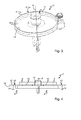
- FIG. 3 shows a perspective view of a first embodiment of the plate according to the invention 4 of a labeling machine 1 (see FIG. 1 ).
- the star wheel 10 which is not shown here for reasons of clarity, forms a support surface 12 for a roll material 6 and is enclosed by a security device 8 due to a risk of injury during the labeling process. Therefore, an all-round protection 14 is designed and arranged as a safety device 8 so that an upper edge 15 of the all-round protection 14 with the support surface 12 for the roll material 6 is aligned in the axial direction A, so that access to the star wheel 10 is prevented.
- the all-round protection 14 is fixed in the labeling process of the rotating plate 4, so that the operator is no longer exposed to injury risk, since it is prevented between the defined support surface 12 and a plate plane 16 (see FIG. 4 ) to enter.
- FIG. 4 shows a partial and schematic side view of the embodiment according to FIG. 3 of the plate according to the invention 4. In FIG. 3 already all essential features are described.
- FIG. 5 4 shows a perspective partial view of a second embodiment of the safety device 8 according to the invention of the plate 4 of a labeling machine 1.
- the plate 4 has four inserts 18 that are movable perpendicular to the plate plane 16 and are aligned with the plate plane 16 when the roller material 6 is placed on the plate 4.
- the inserts 18 are resiliently biased.
- On the inserts 18 acts, for example, a helically wound component (not shown) so as to achieve the required bias.
- the elastic bias is generated by a spiral spring, so that by a contact operation of an operator, a spacing between a defined support surface 12 (see FIG. 7 ), here generated by the spiral spring, and the plate plane 16 is created.
- the plate 4 has four spring-loaded inserts 18 positioned at a distance of 90 degrees, better operability is ensured when changing the rollers 6. This is based on the fact that an operator of a labeling machine 1, no matter in which position the plate 4 interrupts a further rotation in a consumption of a roll material 6, grab under the roller 6 without much retooling and thus can lift the roller 6 on the mandrel 11.
- movable inserts 18 are also conceivable in the invention, since various movable inserts 18 are known in the prior art.
- the plate 4 but must have at least one movable insert 18, so that a gripping between the plate 4 and the roller 6 is possible with a change of the rollers 6 for an operator.
- FIGS. 6 and 7 show a partial and schematic side view of the plate 4 according to the invention FIG. 5 in which the mobility of inserts 18 with and without attached roll material 6 is shown.
- the roll material 6 rests on the plate plane 16, so that the movable inserts 18 are lowered in the axial direction A and thus aligned with the plate plane 16.
- FIG. 7 the deposits 18 in the axial direction A, since no roll material 6 rests on the plate level 16.
- FIG. 8 shows a further embodiment of the embodiment of the plate 4 according to the invention a labeling 1 after FIG. 4 ,
- the plate 4 has in addition to four movable inserts 18 a safety device 8 in the form of a pneumatic fixation 20, which is designed such that a roll material 6 is pneumatically fixed in the axial direction A of the plate 4, wherein this fixation 20, for example via compressed air.
- the pneumatic fixation 20 provides a drain valve 22, via which the fixation 20 in the axial direction A can be released. Consequently, the roller material 6 acts as long as frictionally together with the plate 4 until a release via the drain valve 22 by an operator of a labeling machine 1 is caused.
- the embodiments just described for labeling machines 1 of the FIGS. 3 to 5 be transferred to other devices 2 for receiving roll material 6.
- a use of a plate 4 as described above can thus be used everywhere where rotating plates 4 are used for receiving roll material 6 are used.
Landscapes
- Labeling Devices (AREA)
Abstract
Description
- Die gegenwärtige Erfindung betrifft eine Etikettiermaschine zur Verarbeitung von Rollenmaterial mit mindestens einem drehbar gelagerten Teller.
- Ferner betrifft die Erfindung eine Vorrichtung zur Aufnahme von Rollenmaterial. Hierzu liegt das Rollenmaterial mit einer Stirnseite auf einem Teller auf.
- Für die Durchführung der Etikettierung, die meist bei Dosen, PET-Flaschen oder Glasflaschen angewendet wird, gibt es zwei Durchführungsmöglichkeiten. Zum einen kann die Etikettierung mit bereits zugeschnittenen Etiketten aus einem Magazin und zum anderen kann die Etikettierung mit Etiketten von der Rolle erfolgen. Um den personellen Aufwand, wie beispielsweise für das Wechseln der Etikettierzuschnittsmagazine zu verringern, hat sich die zweite Möglichkeit immer mehr durchgesetzt.
- Dabei wird das auf den Gegenstand aufzubringende Etikett durch Abschneiden von Stücken von einem Endlosetikettenband erst kurz vor der Etikettierung erzeugt.
- Bekannt sind beispielsweise Rundumetikettiermaschinen der Anmelderin vom Typ Contiroll. Bei dieser Maschine wird ein bedrucktes, Schnittmarken aufweisendes Etikettenband mittels einem Rollenpaar von einer Vorratsrolle, die auf einem Teller während des Etikettierungsprozesses drehbar gelagert ist, abgezogen und dem Druckbild entsprechend stellungsgerecht kontinuierlich einer umlaufenden Vakuumwalze zugeführt, auf der das Abschneiden der Einzeletiketten vom Band erfolgt.
- Der Schneidvorgang wird dabei auf die Weise durchgeführt, dass auf der Vakuumwalze Messer angebracht sind, die an einem starren Gegenmesser vorbeigeführt werden, an dem der Schnitt erfolgt. Anschließend wird das erzeugte Einzeletikett an den Greifzylinder übergeben, der es an der Beleimungsstation vorbeiführt und mit einem Leimmuster versieht. Der zu etikettierende Gegenstand wird an dem Greifzylinder zur Etikettenaufbringung vorbeigeführt, wobei ein Einzeletikett durch Drehen des Gegenstandes auf dessen Umfang vollständig aufgewickelt wird. Nach dem Aufwickeln überlappt das Etikettenende den Etikettenanfang und wird mit diesem verklebt.
- Eine Etikettiermaschine, wie oben beschrieben, ist in der deutschen Gebrauchsmusterschrift
DE 20 2005 002 793 U1 offenbart. Der Nachteil der mangelnden Flexibilität im Hinblick auf die bereitzustellenden Etikettenlängen für unterschiedlich zu etikettierende Gegenstände ist hier durch eine flexible Etikettiervorrichtung behoben worden, so dass nicht die Vakuumtrommel und das Schneidmesser als Garniturteil bei Gegenständen, dessen Umfang kleiner oder größer des vorherigen Gegenstands ist, ausgewechselt werden muss. - Gemäß dem Stand der Technik kann ein Teller der Etikettiermaschine eine Sternscheibe aufweisen, die für das Rollenmaterial eine Auflagefläche bildet. Sternscheiben werden bis dato zur Erleichterung bei einem Wechsel des Rollenmaterials eingesetzt, da diese eine Distanz zwischen dem Teller und der Rolle bilden. Somit wird das Problem, dass das Rollenmaterial plan auf dem glatten Teller aufliegt, umgangen. Durch diese Distanz ist dem Bediener einer solchen Etikettiermaschine insofern geholfen, dass er bei einem Wechsel des Rollenmaterials durch die von der Distanz geschaffene Kontur unter die Rolle greifen kann.
- Jedoch birgt eine solche Ausführung auch eine Gefahr während des Etikettierungsprozesses. Die Gefahr besteht darin, dass ein Benutzer während des Betriebes der Etikettiermaschine in den drehenden Teller greift, was zu Verletzungen führen kann. Eine Sicherheitsvorrichtung soll dieses Risiko vermeiden beziehungsweise verringern.
- Aufgabe der gegenwärtigen Erfindung ist, eine Etikettiermaschine zur Verarbeitung von Rollenmaterial bereitzustellen, die während eines Etikettierungsprozesses für einen Benutzer eine bestehende Verletzungsgefahr reduziert und gleichzeitig die allgemeine Bedienbarkeit bei einem Wechsel des Rollenmaterials oder eines Rollenkerns erleichtert.
- Die obige Aufgabe wird durch eine Etikettiermaschine gelöst, die die Merkmale im Anspruch 1 umfasst.
- Eine weitere Aufgabe der Erfindung ist, eine Vorrichtung zur Aufnahme von Rollenmaterial zu schaffen, die während eines Betriebs für einen Benutzer eine bestehende Verletzungsgefahr reduziert und gleichzeitig die allgemeine Bedienbarkeit bei einem Wechsel des Rollenmaterials oder eines Rollenkerns erleichtert.
- Die obige Aufgabe wird durch eine Vorrichtung gelöst, die die Merkmale im Anspruch 8 umfasst.
- Eine Etikettiermaschine, wie sie gemäß der Erfindung zur Verarbeitung von Rollenmaterial verwendet wird, verfügt über mindestens einen drehbar gelagerten Teller, wobei der Teller mindestens eine Sicherheitsvorrichtung aufweist. Die Sicherheitsvorrichtung ist derart gestaltet, dass zum einen bei einem drehenden Teller ein Zugriff zwischen einer definierten Auflagefläche und einer Tellerebene ausgeschlossen und somit während eines Etikettierungsprozesses für einen Benutzer eine bestehende Verletzungsgefahr reduziert ist. Zum anderen ist die Sicherheitsvorrichtung derart gestaltet, dass bei einem ruhenden Teller zum Wechsel des Rollenmaterials oder eines Rollenkerns die definierte Auflagefläche von der Tellerebene beabstandet ist und folglich die allgemeine Bedienbarkeit erleichtert. Der Rollenkern ist in diesem Zusammenhang der Kern auf dem das Rollenmaterial aufgewickelt ist und zurückbleibt, wenn das zu etikettierende Material aufgebraucht ist. Im weiteren Verlauf wird der Einfachheit halber sowohl für die Begriffe Rollenmaterial und Rollenkern ausschließlich die Bezeichnung Rollenmaterial verwendet.
- Der Teller zur Aufnahme und Lagerung von Rollenmaterial besteht vorzugsweise aus Plexiglas. Auf eine detaillierte Beschreibung des Tellers hinsichtlich der Materialausführung wird hier nicht eingegangen, da es für einen Fachmann selbstverständlich ist, dass der Teller aus verschiedensten Werkstoffen hergestellt sein kann.
- Um den Nachteilen der aus dem Stand der Technik bekannten Vorrichtungen zu begegnen, soll eine erfindungsgemäße Sicherheitsvorrichtung das Risiko von Verletzungen der vorgenannten Art vermeiden.
- Gemäß einer ersten Ausführungsform ist die erfindungsgemäße Sicherheitsvorrichtung des Tellers als Rundumschutz daher derart ausgebildet und angeordnet, dass eine Oberkante des Rundumschutzes mit der Auflagefläche für das Rollenmaterial fluchtet und dadurch einen Zugriff auf die Sternscheibe verhindert. Vorzugsweise umschließt ein feststehender Rundumschutz den sich während des Etikettierungsprozesses drehenden Teller. Dementsprechend ist ein Bediener einer solchen Etikettiermaschine vor der Gefahr und dem damit verbunden Verletzungsrisiko der Sternscheibe, das heißt die Beabstandung zwischen der definierten Auflagefläche und der Tellerebene bezüglich eines Hineingreifens, verhindert und zugleich geschützt.
- Eine zweite, bevorzugte Ausführungsform der erfindungsgemäßen Sicherheitsvorrichtung des Tellers sieht vor, dass der Teller mindestens eine derart senkrecht zur Tellerebene bewegbare Einlage aufweist, die bei einem auf dem Teller aufgesetzten Rollenmaterial mit der Tellerebene fluchtet.
- Durch diese Ausführung kann die zuvor erwähnte Sternscheibe sowie die Sicherheitsvorrichtung in Form eines Rundumschutzes weggelassen werden, da zum einen die mindestens eine bewegbare Einlage ein Greifen unter die Rolle beim Wechsel des Rollenmaterials ermöglicht und erleichtert, und zum anderen keine Verletzungsgefahr für den Bediener bezogen auf die Sternscheibe und des Zugriffs während des drehenden Tellers beim Etikettierungsprozesses besteht, da die mindestens eine Einlage herunter bewegt wird und aufgrund der dadurch hervorgerufenen Bewegung der mindestens einen Einlage axial zum Teller, die Rolle vollständig auf der Tellerebene aufliegt. Eine Eingriffsmöglichkeit des Bedieners zwischen die Rolle und die Tellerebene ist somit nicht gegeben.
- Der Teller kann insbesondere vorsehen, dass mindestens eine Einlage elastisch vorgespannt ist. Vorzugsweise ist eine solche elastische Vorspannung durch eine gefederte Einlage ausgeführt, die auf mechanische oder auf sonstige Weise eine Federung schafft, wie beispielsweise Bauformen aus Draht mit schrauben- oder spiralförmig gewickelten oder stabförmig gestreckten oder abgeknickten Bauteilen, die zum Aufbringen beziehungsweise zum Reduzieren einer bestimmten Kraft dienen.
- Ein weiterer Vorteil besteht darin, dass der Teller mindestens eine, vorzugsweise vier elastische, vorgespannte Einlagen aufweist. Anhand dieser Anordnung, wie beispielsweise durch vier gefederte in einem Abstand von 90 Grad positionierte Einlagen, ist eine bessere Bedienbarkeit bei einem Wechsel des Rollenmaterials gesichert. Ein Bediener einer Etikettiermaschine kann dann, egal in welcher Position der Teller bei Aufbrauch eines Rollenmaterials das Drehen unterbricht, ohne großen Umrüstaufwand unter die Rolle greifen und die aufgebrauchte Rolle gegen ein neues und volles Rollenmaterial austauschen, so dass ein im Fachjargon bekannter "fliegender Wechsel" des Rollenmaterials erzielt werden kann.
- Zusätzlich kann die Etikettiermaschine eine Sicherheitsvorrichtung in Form einer pneumatischen Fixierung vorsehen, die derart ausgebildet ist, dass das Rollenmaterial pneumatisch in axialer Richtung des Tellers fixiert ist. Vorzugsweise ist das Rollenmaterial über einen pneumatischen Mechanismus mit dem Teller verbunden.
- Weiterhin sieht die pneumatische Fixierung zur Erreichung der oben genannten Aufgabe der Etikettiermaschine ein Ablassventil vor, über das die Fixierung in axialer Richtung lösbar ist. Demnach ist das Rollenmaterial solange auf dem Teller pneumatisch in axialer Richtung fixiert, bis ein Entspannen über das Ablassventil von einem Bediener hervorgerufen wird. Durch diese Ausführung lassen sich Umrüstzeiten verringern und die Bedienung erheblich erleichtern.
- Bei weiteren Ausgestaltungen des Tellers kann es möglich sein, dass die oben erwähnten Sicherheitsvorrichtungen gleichzeitig verwendet werden, d. h. der Rundumschutz wirkt mit der mindestens einen bewegbaren Einlage zusammen. Optional kann die erfindungsgemäße Etikettiermaschine zudem noch die pneumatische Fixierung vorsehen. Eine weitere Möglichkeit ist, dass der Rundumschutz zusammen mit der pneumatischen Fixierung wirkt ohne die Integration einer mindestens bewegbaren Einlage. Daher ist die Variationsmöglichkeit, wie der Teller einer erfindungsgemäßen Etikettiermaschine ausgestaltet sein kann, vielfältig.
- Wie bereits in den Aufgaben der vorliegenden Erfindung erwähnt, reduziert auch die Vorrichtung zur Aufnahme von Rollenmaterial eine die während eines Betriebs für einen Benutzer bestehende Verletzungsgefahr und erleichtert die allgemeine Bedienbarkeit eines Wechsels des Rollenmaterials. Die gegenwärtige Erfindung ist somit nicht nur auf den Einsatz bei Etikettiermaschinen beschränkt. Die Erfindung findet überall dort Anwendung, wo es gilt, Rollen mit aufgerolltem Folienmaterial auf einen Drehteller aufzusetzen beziehungsweise auszutauschen.
- Demzufolge können die oben beschrieben Ausführungsformen für die Etikettiermaschine zur Verarbeitung von Rollenmaterial analog auf die Vorrichtung zur Aufnahme von Rollenmaterial übertragen werden und müssen daher nicht mehr explizit aufgeführt werden. Eine Verwendung eines wie oben beschriebenen Tellers kann somit auch für andere Anwendungsbereiche herangezogen werden, nämlich überall dort, wo drehende Teller zur Aufnahme von Rollenmaterial zum Einsatz kommen.
- Im Folgenden sollen die Erfindung und ihre Vorteile anhand der beigefügten Figuren erläutert werden. Dabei zeigen:
-
Figur 1 einen schematischen Aufbau einer Etikettiermaschine gemäß dem Stand der Technik; -
Figur 2 eine perspektivische Ansicht eines Tellers gemäß dem Stand der Technik, wie er bei einer Etikettiermaschine nachFigur 1 verwendet werden kann; -
Figur 3 eine perspektivische Ansicht einer ersten Ausführungsform des erfindungsgemäßen Tellers einer Etikettiermaschine; -
Figur 4 eine schematische Seitenansicht der Ausführungsform des erfindungsgemäßen Tellers nachFigur 3 ; -
Figur 5 eine perspektivische Draufsicht einer zweiten Ausführungsform des erfindungsgemäßen Tellers einer Etikettiermaschine; -
Figur 6 und 7 eine teilweise und schematische Seitenansicht des erfindungsgemäßen Tellers gemäßFigur 5 , bei dem die Bewegbarkeit der Einlagen mit und ohne aufgesetzten Rollenmaterial dargestellt ist; und -
Figur 8 eine perspektivische Ansicht einer weiteren Ausführungsform des erfindungsgemäßen Tellers einer Etikettiermaschine nachFigur 4 . - Für gleiche oder gleich wirkende Elemente der Erfindung werden identische Bezugszeichen verwendet. Ferner werden der Übersicht halber nur Bezugszeichen in den einzelnen Figuren dargestellt, die für die Beschreibung der jeweiligen Figur erforderlich sind. Die dargestellten Ausführungsformen stellen lediglich Beispiele dar, wie die erfindungsgemäße Etikettiermaschine zur Verarbeitung von Rollenmaterial und die Vorrichtung zur Aufnahme von Rollenmaterial ausgestaltet sein können und stellen keine abschließende Begrenzung der Erfindung dar.
-
Figur 1 zeigt den schematischen Aufbau einer Etikettiermaschine 1 gemäß dem Stand der Technik. Die Etikettiermaschine 1 ist hier als eine Rundumetikettiermaschine dargestellt. Bei Rundumetikettiermaschinen wird aktuell das Rollenmaterial 6 auf einem Teller 4 gelagert, der vorzugsweise aus Plexiglas besteht. Dieser Teller 4 dreht sich während des Etikettierungsprozesses. Nachdem das Rollenmaterial 6 aufgebraucht ist oder wenn ein Produktwechsel ansteht, muss dieses wieder von dem Teller 4 über einen feststehenden Aufnahmedorn 11 genommen werden und durch ein neues oder anderes Rollenmaterial 6 ersetzt werden. Beim Wechsel dieses Rollenmaterials 6 tritt das Problem auf, dass die Rolle 6 plan auf dem glatten Teller 4 aufliegt und der Bediener nicht unter die Rolle 6 greifen kann. Um die Bedienung bei einem Wechsel des Rollenmaterials 6 zu erleichtern, wurden nach dem bisherigen Stand der Technik sogenannte Sternscheiben 10 (sieheFigur 2 ) verwendet. -
Figur 2 zeigt einen schematischen Aufbau eines Tellers 4 einer Etikettiermaschine 1 nachFigur 1 , mit dem Rollenmaterial 6 (sieheFigur 1 ) gemäß dem Stand der Technik getragen werden kann. Hier wurde bereits Abhilfe durch eine Sternscheibe 10 bezüglich des inFigur 1 beschriebenen Problems eines auf einem Teller 4 plan aufliegenden Rollenmaterials 6 geschaffen. Die Sternscheibe 10 bildet eine Auflagefläche 12 für das Rollenmaterial 6, so dass eine Erleichterung für einen Bediener bei einem Wechsel der Rollen 6 durch die zwischen dem Teller 4 und der Rolle 6 gebildete Distanz geschaffen ist. Durch die von der Distanz geschaffene Kontur, ist dem Bediener insofern geholfen, dass er problemlos unter die Rolle 6 greifen kann. - Ferner zeigt die
Figur 2 eine im Stand der Technik bekannte pneumatische Spanneinheit 21, die ein Rollenmaterial 6 auf dem Teller 4 sichert, wobei diese aber durch großen Aufwand über eine Blaspistole manuell von einem Bediener gespannt werden muss. Zum Wechsel des Rollenmaterials 6 ist des Weiteren ein spitzer Gegenstand notwendig, um ein Ventil 22 zu betätigen, so dass der Kraftschluss zwischen der Rolle 6 und dem Teller 4 gelöst wird. -
Figur 3 zeigt eine perspektivische Ansicht einer ersten Ausführungsform des erfindungsgemäßen Tellers 4 einer Etikettiermaschine 1 (sieheFigur 1 ). Die Sternscheibe 10, welche aus Gründen der Übersichtlichkeit hier nicht dargestellt ist, bildet eine Auflagefläche 12 für ein Rollenmaterial 6 und wird aufgrund einer mit sich bringenden Verletzungsgefahr während des Etikettierungsprozesses von einer Sicherheitsvorrichtung 8 umschlossen. Daher ist ein Rundumschutz 14 als Sicherheitsvorrichtung 8 so ausgebildet und angeordnet, dass eine Oberkante 15 des Rundumschutzes 14 mit der Auflagefläche 12 für das Rollenmaterial 6 derart in axialer Richtung A fluchtet, so dass ein Zugriff auf die Sternscheibe 10 verhindert ist. Der Rundumschutz 14 ist beim Etikettierungsprozess des drehenden Tellers 4 feststehend, so dass der Bediener keinem Verletzungsrisiko mehr ausgesetzt ist, da er gehindert ist, zwischen die definierte Auflagefläche 12 und eine Tellerebene 16 (sieheFigur 4 ) hineinzulangen. -
Figur 4 zeigt eine teilweise und schematische Seitenansicht der Ausführungsform nachFigur 3 des erfindungsgemäßen Tellers 4. InFigur 3 sind bereits alle wesentlichen Merkmale beschrieben. -
Figur 5 zeigt eine perspektivische Teilansicht einer zweiten Ausführungsform der erfindungsgemäßen Sicherheitsvorrichtung 8 des Tellers 4 einer Etikettiermaschine 1. Der Teller 4 weist vier senkrecht zur Tellerebene 16 bewegbare Einlagen 18 auf, die bei einem auf dem Teller 4 aufgesetzten Rollenmaterial 6 mit der Tellerebene 16 fluchten. Die Einlagen 18 sind elastisch vorgespannt. Auf die Einlagen 18 wirkt beispielsweise ein spiralförmig gewickeltes Bauteil (nicht dargestellt), um so die erforderliche Vorspannung zu erzielen. Im einfachsten Fall wird die elastische Vorspannung durch eine Spiralfeder erzeugt, so dass durch eine Kontaktbetätigung eines Bedieners eine Beabstandung zwischen einer definierten Auflagefläche 12 (sieheFigur 7 ), hier durch die Spiralfederung erzeugt, und der Tellerebene 16 geschaffen wird. - Auf der Grundlage, dass der Teller 4 vier gefederte und in einem Abstand von 90 Grad positionierte Einlagen 18 aufweist, ist eine bessere Bedienbarkeit bei einem Wechsel der Rollen 6 gewährleistet. Dies beruht darauf, dass ein Bediener einer Etikettiermaschine 1, egal in welcher Position der Teller 4 bei einem Aufbrauch eines Rollenmaterials 6 ein weiteres Drehen unterbricht, ohne großen Umrüstaufwand unter die Rolle 6 greifen und somit die Rolle 6 über den Aufnahmedorn 11 heben kann.
- Es ist für den Fachmann selbstverständlich, dass bei der Erfindung auch andere Ausführungsformen für die Ausbildung von bewegbaren Einlagen 18 denkbar sind, da verschiedene bewegbare Einlagen 18 im Stand der Technik bekannt sind. Der Teller 4 muss aber mindestens eine bewegbare Einlage 18 aufweisen, so dass ein Greifen zwischen dem Teller 4 und der Rolle 6 bei einem Wechsel der Rollen 6 für einen Bediener möglich ist.
-
Figuren 6 und 7 zeigen eine teilweise und schematische Seitenansicht des erfindungsgemäßen Tellers 4 gemäßFigur 5 , bei dem die Bewegbarkeit von Einlagen 18 mit und ohne aufgesetztes Rollenmaterial 6 dargestellt ist. Bei der inFigur 6 gezeigten Darstellung liegt das Rollenmaterial 6 auf der Tellerebene 16 auf, so dass die bewegbaren Einlagen 18 in axialer Richtung A abgesenkt sind und somit mit der Tellerebene 16 fluchten. Hingegen stehen beiFigur 7 die Einlagen 18 in axialer Richtung A hervor, da kein Rollenmaterial 6 auf der Tellerebene 16 aufliegt. - Die in diesen Darstellungen zu entnehmenden Merkmale einschließlich ihrer Bezugszeichen sind identisch mit der Ausführungsform nach
Figur 5 und sind dieser daher zu entnehmen. -
Figur 8 zeigt eine weitere Ausführungsform der Ausgestaltung des erfindungsgemäßen Tellers 4 einer Etikettiermaschine 1 nachFigur 4 . Der Teller 4 weist neben vier bewegbaren Einlagen 18 eine Sicherheitsvorrichtung 8 in Form einer pneumatischen Fixierung 20 auf, die derart ausgebildet ist, dass ein Rollenmaterial 6 pneumatisch in axialer Richtung A des Tellers 4 fixiert ist, wobei diese Fixierung 20 beispielsweise über Druckluft erfolgt. - Ferner sieht die pneumatische Fixierung 20 ein Ablassventil 22 vor, über das die Fixierung 20 in axialer Richtung A lösbar ist. Demzufolge wirkt das Rollenmaterial 6 solange mit dem Teller 4 kraftschlüssig zusammen, bis ein Entspannen über das Ablassventil 22 von einem Bediener einer Etikettiermaschine 1 hervorgerufen wird.
- Wie bereits in der Beschreibung der vorliegenden Erfindung erwähnt, können die eben beschriebenen Ausführungsformen für Etikettiermaschinen 1 der
Figuren 3 bis 5 auch auf andere Vorrichtungen 2 zur Aufnahme von Rollenmaterial 6 übertragen werden. Eine Verwendung eines wie oben beschriebenen Tellers 4 kann somit überall dort angewandt werden, wo drehende Teller 4 zur Aufnahme von Rollenmaterial 6 zum Einsatz kommen. - Die gegenwärtige Erfindung ist in Bezug auf bevorzugte Ausführungsformen beschrieben worden. Dennoch können Änderungen und Abwandlungen der hier vorgeschlagenen Gestaltungen der Etikettiermaschine zur Verarbeitung von Rollenmaterial und der Vorrichtung zur Aufnahme von Rollenmaterial durchgeführt werden, ohne dabei den Schutzbereich der nachstehenden Ansprüche zu verlassen.
-
- 1
- Etikettiermaschine
- 2
- Vorrichtung
- 4
- Teller
- 6
- Rollenmaterial, Rolle
- 8
- Sicherheitsvorrichtung
- 10
- Sternscheibe
- 11
- Aufnahmedorn
- 12
- Auflagefläche
- 14
- Rundumschutz
- 15
- Oberkante
- 16
- Tellerebene
- 18
- Einlage
- 20
- Fixierung
- 21
- Spanneinheit
- 22
- Ablassventil, Ventil
- A
- axiale Richtung
Claims (14)
- Etikettiermaschine (1) zur Verarbeitung von Rollenmaterial (6) mit mindestens einem drehbar gelagerten Teller (4),
dadurch gekennzeichnet, dass
der Teller (4) mindestens eine Sicherheitsvorrichtung (8) aufweist, die derart ausgestaltet ist, dass bei einem drehenden Teller (4) ein Zugriff zwischen einer definierten Auflagefläche (12) und einer Tellerebene (16) ausgeschlossen ist und/oder dass bei einem ruhenden Teller (4) zum Wechsel des Rollenmaterials (6) die definierte Auflagefläche (12) von der Tellerebene (16) beabstandet ist. - Etikettiermaschine (1) nach Anspruch 1, wobei der Teller (4) eine Sternscheibe (10) aufweist, die für das Rollenmaterial (6) eine Auflagefläche (12) bildet und wobei die Sicherheitsvorrichtung (8) des Tellers (4) als Rundumschutz (14) ausgebildet und derart angeordnet ist, dass eine Oberkante (15) des Rundumschutzes (14) mit der Auflagefläche (12) fluchtet.
- Etikettiermaschine (1) nach Anspruch 1, wobei die Sicherheitsvorrichtung (8) des Tellers (4) mindestens eine derart senkrecht zur Tellerebene (16) bewegbare Einlage (18) aufweist, die bei einem auf dem Teller (4) aufgesetzten Rollenmaterial (6) mit der Tellerebene (16) fluchtet.
- Etikettiermaschine (1) nach Anspruch 3, wobei die mindestens eine Einlage (18) elastisch vorgespannt ist.
- Etikettiermaschine (1) nach den Ansprüchen 3 und 4, wobei der Teller (4) vier elastische, vorgespannte Einlagen (18) aufweist.
- Etikettiermaschine (1) nach den Ansprüchen 1 sowie 3 bis 5, wobei die Sicherheitsvorrichtung (8) eine pneumatische Fixierung (20) ist, die das Rollenmaterial (6) pneumatisch in axialer Richtung (A) des Tellers (4) fixiert.
- Etikettiermaschine (1) nach Anspruch 6, wobei die pneumatische Fixierung (20) ein Ablassventil (22) aufweist, über das die Fixierung (20) in axialer Richtung (A) lösbar ist.
- Vorrichtung (2) zur Aufnahme von Rollenmaterial (6), wobei das Rollenmaterial (6) mit einer Stirnseite auf einem Teller (4) aufliegt,
dadurch gekennzeichnet, dass
der Teller (4) mindestens eine Sicherheitsvorrichtung (8) aufweist, die derart ausgestaltet ist, dass bei einem drehenden Teller (4) ein Zugriff zwischen einer definierten Auflagefläche (12) und einer Tellerebene (16) ausgeschlossen ist und/oder dass bei einem ruhenden Teller (4) zum Wechsel des Rollenmaterials (6) die definierte Auflagefläche (12) von der Tellerebene (16) beabstandet ist. - Vorrichtung (2) nach Anspruch 8, wobei der Teller (4) eine Sternscheibe (10) aufweist, die für das Rollenmaterial (6) eine Auflagefläche (12) bildet und wobei die Sicherheitsvorrichtung (8) des Tellers (4) als Rundumschutz (14) ausgebildet und derart angeordnet ist, dass eine Oberkante (15) des Rundumschutzes (14) mit der Auflagefläche (12) fluchtet.
- Vorrichtung (2) nach Anspruch 8, wobei die Sicherheitsvorrichtung (8) des Tellers (4) mindestens eine derart senkrecht zur Tellerebene (16) bewegbare Einlage (18) aufweist, die bei einem auf dem Teller (4) aufgesetzten Rollenmaterial (6) mit der Tellerebene (16) fluchtet.
- Vorrichtung (2) nach Anspruch 10, wobei die mindestens eine Einlage (18) elastisch vorgespannt ist.
- Vorrichtung (2) nach den Ansprüchen 10 und 11, wobei der Teller (4) vier elastische, vorgespannte Einlagen (18) aufweist.
- Vorrichtung (2) nach den Ansprüchen 8 sowie 10 bis 12, wobei die Sicherheitsvorrichtung (8) eine pneumatische Fixierung (20) ist, die das Rollenmaterial (6) pneumatisch in axialer Richtung (A) des Tellers (4) fixiert.
- Vorrichtung (2) nach Anspruch 13, wobei die pneumatische Fixierung (20) ein Ablassventil (22) aufweist, über das die Fixierung (20) in axialer Richtung (A) lösbar ist.
Applications Claiming Priority (1)
| Application Number | Priority Date | Filing Date | Title |
|---|---|---|---|
| DE102010016063.6A DE102010016063B4 (de) | 2010-03-22 | 2010-03-22 | Etikettiermaschine zur Verarbeitung von Rollenmaterial und Vorrichtung zur Aufnahme von Rollenmaterial |
Publications (3)
| Publication Number | Publication Date |
|---|---|
| EP2368803A2 true EP2368803A2 (de) | 2011-09-28 |
| EP2368803A3 EP2368803A3 (de) | 2013-07-17 |
| EP2368803B1 EP2368803B1 (de) | 2015-07-29 |
Family
ID=44140718
Family Applications (1)
| Application Number | Title | Priority Date | Filing Date |
|---|---|---|---|
| EP11155394.7A Active EP2368803B1 (de) | 2010-03-22 | 2011-02-22 | Vorrichtung zur Aufnahme von Rollenmaterial |
Country Status (3)
| Country | Link |
|---|---|
| EP (1) | EP2368803B1 (de) |
| CN (1) | CN102198873B (de) |
| DE (1) | DE102010016063B4 (de) |
Cited By (2)
| Publication number | Priority date | Publication date | Assignee | Title |
|---|---|---|---|---|
| WO2013164862A1 (en) * | 2012-05-04 | 2013-11-07 | Kosme S.R.L. Unipersonale | Device for feeding self-adhesive or "pressure sensitive" labels to a labelling machine |
| CN115417207A (zh) * | 2022-09-14 | 2022-12-02 | 江苏万宝瑞达高新技术有限公司 | 一种热敏膜生产用旋转式自动上料装置及其使用方法 |
Families Citing this family (3)
| Publication number | Priority date | Publication date | Assignee | Title |
|---|---|---|---|---|
| DE102013017574A1 (de) * | 2013-10-24 | 2015-04-30 | Espera-Werke Gmbh | Vorrichtung zum Wechseln von Bonrollen einer Etikettiermaschine und entsprechendes Verfahren zum Wechseln von Bonrollen |
| CN111099102A (zh) * | 2019-11-25 | 2020-05-05 | 秦皇岛艾科晟科技有限公司 | 自动化贴标、换标及其检测装置 |
| DE102024106385A1 (de) * | 2024-03-06 | 2025-09-11 | Krones Aktiengesellschaft | System, Verfahren und Etikettiervorrichtung zum ergonomischen Etikettenrollenwechsel |
Citations (1)
| Publication number | Priority date | Publication date | Assignee | Title |
|---|---|---|---|---|
| DE202005002793U1 (de) | 2005-02-22 | 2005-04-21 | Krones Ag | Rundumetikettiervorrichtung |
Family Cites Families (19)
| Publication number | Priority date | Publication date | Assignee | Title |
|---|---|---|---|---|
| US3568945A (en) * | 1968-11-12 | 1971-03-09 | Burroughs Corp | Tape reel |
| US3656700A (en) * | 1970-06-24 | 1972-04-18 | Metro Machine & Engineering Co | Apparatus for winding storing and distributing punched paper tape |
| US3810591A (en) * | 1972-07-13 | 1974-05-14 | Stanley Works | Dispensing machine for coil stock |
| DE2744801A1 (de) * | 1977-10-03 | 1979-04-12 | Interlake Inc | Ausgabevorrichtung und -system fuer bandmaterial |
| US4290563A (en) * | 1979-11-07 | 1981-09-22 | Reel-O-Matic Systems, Incorporated | Method and apparatus for dispensing coiled materials |
| GB8604996D0 (en) * | 1986-02-28 | 1986-04-09 | Harland Mach Syst | Continuous supply of elongate material |
| US4863112A (en) * | 1986-04-18 | 1989-09-05 | Bruderer Ag | Method for storing coils of wound band-like blank material and for charging a processing machine, and an installation for this purpose |
| DE3740806C2 (de) * | 1987-12-02 | 1996-07-25 | Agfa Gevaert Ag | Verfahren zum automatischen Zuführen von Rollen von fotografischem Papier zu einem fotografischen Printer und nach diesem Verfahren arbeitende Vorrichtung |
| DE3907792A1 (de) * | 1988-03-30 | 1989-10-19 | Stoeckle Hans | Vorrichtung zum abwickeln von kabeln von einer kabelrolle oder kabelring |
| US5193758A (en) * | 1989-02-27 | 1993-03-16 | Bruderer Ag | Apparatus for holding and for unwinding coils |
| ATE126739T1 (de) * | 1990-10-12 | 1995-09-15 | Bruderer Ag | Verfahren zum beschicken einer bearbeitungsmaschine mit einem feinzentrierschritt und vorrichtung hierfür. |
| JPH05170238A (ja) * | 1991-02-07 | 1993-07-09 | Kirin Brewery Co Ltd | ラベル貼り装置 |
| DE29721131U1 (de) * | 1997-10-10 | 1998-04-09 | Spiromaskiner A/S, Gjoevik | Vorrichtung zum Abwickeln eines Bandes von einer Spule |
| FR2770502B1 (fr) * | 1997-11-03 | 2000-01-28 | Ier | Dispositif pour enrouler un ruban et equipement d'impression pourvu de ce dispositif |
| IT244102Y1 (it) * | 1998-07-02 | 2002-03-07 | Finsid S R L | Albero espansibile autocentrante a sistema misto |
| JP2002053115A (ja) * | 2000-08-09 | 2002-02-19 | Lintec Corp | ラベル貼り付け装置 |
| DE10314421B4 (de) * | 2003-03-28 | 2007-05-31 | Kollek, Manfred, Dipl.-Ing. | Vorrichtung zum Ab- und Aufrollen von Leitungsringen, Kabelringen, Kabeltrommeln und ähnlichen Abrollgütern |
| US20060118061A1 (en) * | 2004-12-07 | 2006-06-08 | Timothy Edwards | Bag spool rewind assembly |
| DE102007050012B4 (de) * | 2007-10-17 | 2025-10-23 | Krones Aktiengesellschaft | Etikettieranlage und Vorrichtung zum Verifizieren |
-
2010
- 2010-03-22 DE DE102010016063.6A patent/DE102010016063B4/de active Active
-
2011
- 2011-02-22 EP EP11155394.7A patent/EP2368803B1/de active Active
- 2011-03-22 CN CN201110072439.1A patent/CN102198873B/zh active Active
Patent Citations (1)
| Publication number | Priority date | Publication date | Assignee | Title |
|---|---|---|---|---|
| DE202005002793U1 (de) | 2005-02-22 | 2005-04-21 | Krones Ag | Rundumetikettiervorrichtung |
Cited By (6)
| Publication number | Priority date | Publication date | Assignee | Title |
|---|---|---|---|---|
| WO2013164862A1 (en) * | 2012-05-04 | 2013-11-07 | Kosme S.R.L. Unipersonale | Device for feeding self-adhesive or "pressure sensitive" labels to a labelling machine |
| WO2013164702A1 (en) * | 2012-05-04 | 2013-11-07 | Kosme S.R.L. Unipersonale | Device for feeding self-adhesive or "pressure sensitive" labels to a labelling machine |
| CN104470813A (zh) * | 2012-05-04 | 2015-03-25 | 柯斯梅私人股份公司 | 用于将自粘或者“压敏”标签供给到贴标机的设备 |
| CN104470813B (zh) * | 2012-05-04 | 2016-05-25 | 柯斯梅私人股份公司 | 用于将自粘或者“压敏”标签供给到贴标机的设备 |
| US9540130B2 (en) | 2012-05-04 | 2017-01-10 | Kosme S.R.L. Unipersonale | Device for feeding self-adhesive or “pressure sensitive” labels to a labelling machine |
| CN115417207A (zh) * | 2022-09-14 | 2022-12-02 | 江苏万宝瑞达高新技术有限公司 | 一种热敏膜生产用旋转式自动上料装置及其使用方法 |
Also Published As
| Publication number | Publication date |
|---|---|
| CN102198873B (zh) | 2014-11-05 |
| EP2368803A3 (de) | 2013-07-17 |
| DE102010016063B4 (de) | 2023-10-05 |
| DE102010016063A1 (de) | 2011-09-22 |
| CN102198873A (zh) | 2011-09-28 |
| EP2368803B1 (de) | 2015-07-29 |
Similar Documents
| Publication | Publication Date | Title |
|---|---|---|
| DE3701146C2 (de) | ||
| EP0264347A2 (de) | Einrichtung zum Verarbeiten einer Bahn | |
| DE9016591U1 (de) | Vorrichtung zum Ausstatten von Gefäßen mit Etiketten | |
| EP2368803B1 (de) | Vorrichtung zur Aufnahme von Rollenmaterial | |
| DE102011004976A1 (de) | Etikettiervorrichtung | |
| DE2902315C2 (de) | Vorrichtung zum Etikettieren von Behältern | |
| EP3609714A1 (de) | Drucker zum bedrucken von markiererstreifen | |
| DE2732352A1 (de) | Verfahren und vorrichtung zur herstellung von farbmusterkarten | |
| DE202011001929U1 (de) | Halte- und Abrollvorrichtung für auf Rollen gewickeltes Flach- oder Folienmaterial | |
| DE102010000182A1 (de) | Leimwalze zum Auftrag von Leim auf Etiketten, Verfahren zum Etikettieren von Artikeln und Herstellungsverfahren für eine Leimwalze | |
| CH660577A5 (de) | Geraet zum handhaben von flaechigen materialstuecken und schneidemaschine mit einem solchen geraet. | |
| DE2235511C3 (de) | Einrichtung zum Stanzen von Lochreihen in endlose Papierbahnen an einer Rotationsdruckmaschine | |
| DE202019105707U1 (de) | Sleeve-Etikettiermaschine und deren Sleeve-Etikettiervorrichtung | |
| DE3809146C2 (de) | Vorrichtung zum Zerteilen von Rollen von auf Dornen gewickelter band- oder folienförmiger Ware, insbesonders Papier | |
| DE2259485A1 (de) | Vorrichtung zum verbinden von materialbahnen | |
| DE1436633C3 (de) | Vorrichtung zum Herstellen von be druckten Etiketten | |
| DE102013017574A1 (de) | Vorrichtung zum Wechseln von Bonrollen einer Etikettiermaschine und entsprechendes Verfahren zum Wechseln von Bonrollen | |
| DE69117209T2 (de) | Arretiervorrichtung, insbesondere für einzugsgeführte Wellpappe | |
| DE4441278A1 (de) | Schnittanordnung zum Schneiden von Teebeuteln aus Bahnmaterialien | |
| EP0505533B1 (de) | Einrichtung zum entfernen der restbahn | |
| DE9317428U1 (de) | Schälvorrichtung für Industriewürste | |
| DE1058291B (de) | Verfahren und Vorrichtung zum Neuzurichten von in Bueromaschinen verwendeten Karten | |
| EP2483054B1 (de) | Montagehilfe zum anmontieren von folien sowie dazugehörige halterungseinrichtung | |
| DE102018127757A1 (de) | Vorrichtung und Verfahren zum Anbringen von Traggriffen an Packmittel oder Packmittelgruppen | |
| DE102016116202A1 (de) | Etikettiervorrichtung |
Legal Events
| Date | Code | Title | Description |
|---|---|---|---|
| PUAI | Public reference made under article 153(3) epc to a published international application that has entered the european phase |
Free format text: ORIGINAL CODE: 0009012 |
|
| AK | Designated contracting states |
Kind code of ref document: A2 Designated state(s): AL AT BE BG CH CY CZ DE DK EE ES FI FR GB GR HR HU IE IS IT LI LT LU LV MC MK MT NL NO PL PT RO RS SE SI SK SM TR |
|
| AX | Request for extension of the european patent |
Extension state: BA ME |
|
| PUAL | Search report despatched |
Free format text: ORIGINAL CODE: 0009013 |
|
| RIC1 | Information provided on ipc code assigned before grant |
Ipc: B65C 9/18 20060101AFI20130604BHEP |
|
| AK | Designated contracting states |
Kind code of ref document: A3 Designated state(s): AL AT BE BG CH CY CZ DE DK EE ES FI FR GB GR HR HU IE IS IT LI LT LU LV MC MK MT NL NO PL PT RO RS SE SI SK SM TR |
|
| AX | Request for extension of the european patent |
Extension state: BA ME |
|
| 17P | Request for examination filed |
Effective date: 20140103 |
|
| RBV | Designated contracting states (corrected) |
Designated state(s): AL AT BE BG CH CY CZ DE DK EE ES FI FR GB GR HR HU IE IS IT LI LT LU LV MC MK MT NL NO PL PT RO RS SE SI SK SM TR |
|
| 17Q | First examination report despatched |
Effective date: 20140723 |
|
| GRAP | Despatch of communication of intention to grant a patent |
Free format text: ORIGINAL CODE: EPIDOSNIGR1 |
|
| INTG | Intention to grant announced |
Effective date: 20150216 |
|
| GRAS | Grant fee paid |
Free format text: ORIGINAL CODE: EPIDOSNIGR3 |
|
| GRAA | (expected) grant |
Free format text: ORIGINAL CODE: 0009210 |
|
| AK | Designated contracting states |
Kind code of ref document: B1 Designated state(s): AL AT BE BG CH CY CZ DE DK EE ES FI FR GB GR HR HU IE IS IT LI LT LU LV MC MK MT NL NO PL PT RO RS SE SI SK SM TR |
|
| REG | Reference to a national code |
Ref country code: GB Ref legal event code: FG4D Free format text: NOT ENGLISH |
|
| REG | Reference to a national code |
Ref country code: CH Ref legal event code: EP |
|
| REG | Reference to a national code |
Ref country code: AT Ref legal event code: REF Ref document number: 739057 Country of ref document: AT Kind code of ref document: T Effective date: 20150815 |
|
| REG | Reference to a national code |
Ref country code: IE Ref legal event code: FG4D Free format text: LANGUAGE OF EP DOCUMENT: GERMAN |
|
| REG | Reference to a national code |
Ref country code: DE Ref legal event code: R096 Ref document number: 502011007425 Country of ref document: DE |
|
| REG | Reference to a national code |
Ref country code: LT Ref legal event code: MG4D |
|
| REG | Reference to a national code |
Ref country code: NL Ref legal event code: MP Effective date: 20150729 |
|
| REG | Reference to a national code |
Ref country code: FR Ref legal event code: PLFP Year of fee payment: 6 |
|
| PG25 | Lapsed in a contracting state [announced via postgrant information from national office to epo] |
Ref country code: NO Free format text: LAPSE BECAUSE OF FAILURE TO SUBMIT A TRANSLATION OF THE DESCRIPTION OR TO PAY THE FEE WITHIN THE PRESCRIBED TIME-LIMIT Effective date: 20151029 Ref country code: FI Free format text: LAPSE BECAUSE OF FAILURE TO SUBMIT A TRANSLATION OF THE DESCRIPTION OR TO PAY THE FEE WITHIN THE PRESCRIBED TIME-LIMIT Effective date: 20150729 Ref country code: GR Free format text: LAPSE BECAUSE OF FAILURE TO SUBMIT A TRANSLATION OF THE DESCRIPTION OR TO PAY THE FEE WITHIN THE PRESCRIBED TIME-LIMIT Effective date: 20151030 Ref country code: LT Free format text: LAPSE BECAUSE OF FAILURE TO SUBMIT A TRANSLATION OF THE DESCRIPTION OR TO PAY THE FEE WITHIN THE PRESCRIBED TIME-LIMIT Effective date: 20150729 Ref country code: LV Free format text: LAPSE BECAUSE OF FAILURE TO SUBMIT A TRANSLATION OF THE DESCRIPTION OR TO PAY THE FEE WITHIN THE PRESCRIBED TIME-LIMIT Effective date: 20150729 |
|
| PG25 | Lapsed in a contracting state [announced via postgrant information from national office to epo] |
Ref country code: RS Free format text: LAPSE BECAUSE OF FAILURE TO SUBMIT A TRANSLATION OF THE DESCRIPTION OR TO PAY THE FEE WITHIN THE PRESCRIBED TIME-LIMIT Effective date: 20150729 Ref country code: PL Free format text: LAPSE BECAUSE OF FAILURE TO SUBMIT A TRANSLATION OF THE DESCRIPTION OR TO PAY THE FEE WITHIN THE PRESCRIBED TIME-LIMIT Effective date: 20150729 Ref country code: HR Free format text: LAPSE BECAUSE OF FAILURE TO SUBMIT A TRANSLATION OF THE DESCRIPTION OR TO PAY THE FEE WITHIN THE PRESCRIBED TIME-LIMIT Effective date: 20150729 Ref country code: PT Free format text: LAPSE BECAUSE OF FAILURE TO SUBMIT A TRANSLATION OF THE DESCRIPTION OR TO PAY THE FEE WITHIN THE PRESCRIBED TIME-LIMIT Effective date: 20151130 Ref country code: IS Free format text: LAPSE BECAUSE OF FAILURE TO SUBMIT A TRANSLATION OF THE DESCRIPTION OR TO PAY THE FEE WITHIN THE PRESCRIBED TIME-LIMIT Effective date: 20151129 Ref country code: ES Free format text: LAPSE BECAUSE OF FAILURE TO SUBMIT A TRANSLATION OF THE DESCRIPTION OR TO PAY THE FEE WITHIN THE PRESCRIBED TIME-LIMIT Effective date: 20150729 Ref country code: SE Free format text: LAPSE BECAUSE OF FAILURE TO SUBMIT A TRANSLATION OF THE DESCRIPTION OR TO PAY THE FEE WITHIN THE PRESCRIBED TIME-LIMIT Effective date: 20150729 |
|
| PG25 | Lapsed in a contracting state [announced via postgrant information from national office to epo] |
Ref country code: NL Free format text: LAPSE BECAUSE OF FAILURE TO SUBMIT A TRANSLATION OF THE DESCRIPTION OR TO PAY THE FEE WITHIN THE PRESCRIBED TIME-LIMIT Effective date: 20150729 |
|
| PG25 | Lapsed in a contracting state [announced via postgrant information from national office to epo] |
Ref country code: EE Free format text: LAPSE BECAUSE OF FAILURE TO SUBMIT A TRANSLATION OF THE DESCRIPTION OR TO PAY THE FEE WITHIN THE PRESCRIBED TIME-LIMIT Effective date: 20150729 Ref country code: DK Free format text: LAPSE BECAUSE OF FAILURE TO SUBMIT A TRANSLATION OF THE DESCRIPTION OR TO PAY THE FEE WITHIN THE PRESCRIBED TIME-LIMIT Effective date: 20150729 Ref country code: SK Free format text: LAPSE BECAUSE OF FAILURE TO SUBMIT A TRANSLATION OF THE DESCRIPTION OR TO PAY THE FEE WITHIN THE PRESCRIBED TIME-LIMIT Effective date: 20150729 Ref country code: CZ Free format text: LAPSE BECAUSE OF FAILURE TO SUBMIT A TRANSLATION OF THE DESCRIPTION OR TO PAY THE FEE WITHIN THE PRESCRIBED TIME-LIMIT Effective date: 20150729 |
|
| REG | Reference to a national code |
Ref country code: DE Ref legal event code: R097 Ref document number: 502011007425 Country of ref document: DE |
|
| PG25 | Lapsed in a contracting state [announced via postgrant information from national office to epo] |
Ref country code: RO Free format text: LAPSE BECAUSE OF FAILURE TO SUBMIT A TRANSLATION OF THE DESCRIPTION OR TO PAY THE FEE WITHIN THE PRESCRIBED TIME-LIMIT Effective date: 20150729 Ref country code: BE Free format text: LAPSE BECAUSE OF NON-PAYMENT OF DUE FEES Effective date: 20160229 |
|
| PLBE | No opposition filed within time limit |
Free format text: ORIGINAL CODE: 0009261 |
|
| STAA | Information on the status of an ep patent application or granted ep patent |
Free format text: STATUS: NO OPPOSITION FILED WITHIN TIME LIMIT |
|
| 26N | No opposition filed |
Effective date: 20160502 |
|
| PG25 | Lapsed in a contracting state [announced via postgrant information from national office to epo] |
Ref country code: SI Free format text: LAPSE BECAUSE OF FAILURE TO SUBMIT A TRANSLATION OF THE DESCRIPTION OR TO PAY THE FEE WITHIN THE PRESCRIBED TIME-LIMIT Effective date: 20150729 |
|
| PG25 | Lapsed in a contracting state [announced via postgrant information from national office to epo] |
Ref country code: LU Free format text: LAPSE BECAUSE OF FAILURE TO SUBMIT A TRANSLATION OF THE DESCRIPTION OR TO PAY THE FEE WITHIN THE PRESCRIBED TIME-LIMIT Effective date: 20160222 Ref country code: MC Free format text: LAPSE BECAUSE OF FAILURE TO SUBMIT A TRANSLATION OF THE DESCRIPTION OR TO PAY THE FEE WITHIN THE PRESCRIBED TIME-LIMIT Effective date: 20150729 |
|
| REG | Reference to a national code |
Ref country code: CH Ref legal event code: PL |
|
| GBPC | Gb: european patent ceased through non-payment of renewal fee |
Effective date: 20160222 |
|
| PG25 | Lapsed in a contracting state [announced via postgrant information from national office to epo] |
Ref country code: CH Free format text: LAPSE BECAUSE OF NON-PAYMENT OF DUE FEES Effective date: 20160229 Ref country code: LI Free format text: LAPSE BECAUSE OF NON-PAYMENT OF DUE FEES Effective date: 20160229 |
|
| REG | Reference to a national code |
Ref country code: IE Ref legal event code: MM4A |
|
| REG | Reference to a national code |
Ref country code: FR Ref legal event code: PLFP Year of fee payment: 7 |
|
| PG25 | Lapsed in a contracting state [announced via postgrant information from national office to epo] |
Ref country code: GB Free format text: LAPSE BECAUSE OF NON-PAYMENT OF DUE FEES Effective date: 20160222 Ref country code: IE Free format text: LAPSE BECAUSE OF NON-PAYMENT OF DUE FEES Effective date: 20160222 |
|
| REG | Reference to a national code |
Ref country code: AT Ref legal event code: MM01 Ref document number: 739057 Country of ref document: AT Kind code of ref document: T Effective date: 20160222 |
|
| PG25 | Lapsed in a contracting state [announced via postgrant information from national office to epo] |
Ref country code: AT Free format text: LAPSE BECAUSE OF NON-PAYMENT OF DUE FEES Effective date: 20160222 |
|
| PG25 | Lapsed in a contracting state [announced via postgrant information from national office to epo] |
Ref country code: MT Free format text: LAPSE BECAUSE OF FAILURE TO SUBMIT A TRANSLATION OF THE DESCRIPTION OR TO PAY THE FEE WITHIN THE PRESCRIBED TIME-LIMIT Effective date: 20150729 |
|
| REG | Reference to a national code |
Ref country code: FR Ref legal event code: PLFP Year of fee payment: 8 |
|
| PG25 | Lapsed in a contracting state [announced via postgrant information from national office to epo] |
Ref country code: HU Free format text: LAPSE BECAUSE OF FAILURE TO SUBMIT A TRANSLATION OF THE DESCRIPTION OR TO PAY THE FEE WITHIN THE PRESCRIBED TIME-LIMIT; INVALID AB INITIO Effective date: 20110222 Ref country code: SM Free format text: LAPSE BECAUSE OF FAILURE TO SUBMIT A TRANSLATION OF THE DESCRIPTION OR TO PAY THE FEE WITHIN THE PRESCRIBED TIME-LIMIT Effective date: 20150729 Ref country code: CY Free format text: LAPSE BECAUSE OF FAILURE TO SUBMIT A TRANSLATION OF THE DESCRIPTION OR TO PAY THE FEE WITHIN THE PRESCRIBED TIME-LIMIT Effective date: 20150729 |
|
| PG25 | Lapsed in a contracting state [announced via postgrant information from national office to epo] |
Ref country code: MK Free format text: LAPSE BECAUSE OF FAILURE TO SUBMIT A TRANSLATION OF THE DESCRIPTION OR TO PAY THE FEE WITHIN THE PRESCRIBED TIME-LIMIT Effective date: 20150729 Ref country code: TR Free format text: LAPSE BECAUSE OF FAILURE TO SUBMIT A TRANSLATION OF THE DESCRIPTION OR TO PAY THE FEE WITHIN THE PRESCRIBED TIME-LIMIT Effective date: 20150729 |
|
| PG25 | Lapsed in a contracting state [announced via postgrant information from national office to epo] |
Ref country code: BG Free format text: LAPSE BECAUSE OF FAILURE TO SUBMIT A TRANSLATION OF THE DESCRIPTION OR TO PAY THE FEE WITHIN THE PRESCRIBED TIME-LIMIT Effective date: 20150729 |
|
| PG25 | Lapsed in a contracting state [announced via postgrant information from national office to epo] |
Ref country code: AL Free format text: LAPSE BECAUSE OF FAILURE TO SUBMIT A TRANSLATION OF THE DESCRIPTION OR TO PAY THE FEE WITHIN THE PRESCRIBED TIME-LIMIT Effective date: 20150729 |
|
| PGFP | Annual fee paid to national office [announced via postgrant information from national office to epo] |
Ref country code: FR Payment date: 20251231 Year of fee payment: 16 |
|
| PGFP | Annual fee paid to national office [announced via postgrant information from national office to epo] |
Ref country code: DE Payment date: 20251230 Year of fee payment: 16 |
|
| PGFP | Annual fee paid to national office [announced via postgrant information from national office to epo] |
Ref country code: IT Payment date: 20260122 Year of fee payment: 16 |