EP2366646A2 - Trennvorrichtung, Fixiervorrichtung, Medienübertragungsvorrichtung und Bilderzeugungsvorrichtung - Google Patents
Trennvorrichtung, Fixiervorrichtung, Medienübertragungsvorrichtung und Bilderzeugungsvorrichtung Download PDFInfo
- Publication number
- EP2366646A2 EP2366646A2 EP20110157941 EP11157941A EP2366646A2 EP 2366646 A2 EP2366646 A2 EP 2366646A2 EP 20110157941 EP20110157941 EP 20110157941 EP 11157941 A EP11157941 A EP 11157941A EP 2366646 A2 EP2366646 A2 EP 2366646A2
- Authority
- EP
- European Patent Office
- Prior art keywords
- separating
- conveying
- guiding
- medium
- rotation fulcrum
- Prior art date
- Legal status (The legal status is an assumption and is not a legal conclusion. Google has not performed a legal analysis and makes no representation as to the accuracy of the status listed.)
- Granted
Links
- 210000000078 claw Anatomy 0.000 claims description 171
- 238000011144 upstream manufacturing Methods 0.000 claims description 5
- 238000012986 modification Methods 0.000 description 3
- 230000008021 deposition Effects 0.000 description 2
- 239000010410 layer Substances 0.000 description 2
- 239000000463 material Substances 0.000 description 2
- 230000004048 modification Effects 0.000 description 2
- 238000000926 separation method Methods 0.000 description 2
- 230000007423 decrease Effects 0.000 description 1
- 230000005684 electric field Effects 0.000 description 1
- 229910052736 halogen Inorganic materials 0.000 description 1
- 150000002367 halogens Chemical class 0.000 description 1
- 230000002093 peripheral effect Effects 0.000 description 1
- 239000002344 surface layer Substances 0.000 description 1
Images







Classifications
-
- B—PERFORMING OPERATIONS; TRANSPORTING
- B65—CONVEYING; PACKING; STORING; HANDLING THIN OR FILAMENTARY MATERIAL
- B65H—HANDLING THIN OR FILAMENTARY MATERIAL, e.g. SHEETS, WEBS, CABLES
- B65H5/00—Feeding articles separated from piles; Feeding articles to machines
- B65H5/36—Article guides or smoothers, e.g. movable in operation
-
- G—PHYSICS
- G03—PHOTOGRAPHY; CINEMATOGRAPHY; ANALOGOUS TECHNIQUES USING WAVES OTHER THAN OPTICAL WAVES; ELECTROGRAPHY; HOLOGRAPHY
- G03G—ELECTROGRAPHY; ELECTROPHOTOGRAPHY; MAGNETOGRAPHY
- G03G15/00—Apparatus for electrographic processes using a charge pattern
- G03G15/20—Apparatus for electrographic processes using a charge pattern for fixing, e.g. by using heat
- G03G15/2003—Apparatus for electrographic processes using a charge pattern for fixing, e.g. by using heat using heat
- G03G15/2014—Apparatus for electrographic processes using a charge pattern for fixing, e.g. by using heat using heat using contact heat
- G03G15/2017—Structural details of the fixing unit in general, e.g. cooling means, heat shielding means
- G03G15/2028—Structural details of the fixing unit in general, e.g. cooling means, heat shielding means with means for handling the copy material in the fixing nip, e.g. introduction guides, stripping means
-
- B—PERFORMING OPERATIONS; TRANSPORTING
- B65—CONVEYING; PACKING; STORING; HANDLING THIN OR FILAMENTARY MATERIAL
- B65H—HANDLING THIN OR FILAMENTARY MATERIAL, e.g. SHEETS, WEBS, CABLES
- B65H2301/00—Handling processes for sheets or webs
- B65H2301/50—Auxiliary process performed during handling process
- B65H2301/51—Modifying a characteristic of handled material
- B65H2301/514—Modifying physical properties
- B65H2301/5143—Warming
- B65H2301/51432—Applying heat and pressure
-
- B—PERFORMING OPERATIONS; TRANSPORTING
- B65—CONVEYING; PACKING; STORING; HANDLING THIN OR FILAMENTARY MATERIAL
- B65H—HANDLING THIN OR FILAMENTARY MATERIAL, e.g. SHEETS, WEBS, CABLES
- B65H2404/00—Parts for transporting or guiding the handled material
- B65H2404/60—Other elements in face contact with handled material
- B65H2404/62—Transversely-extending bars or tubes
-
- B—PERFORMING OPERATIONS; TRANSPORTING
- B65—CONVEYING; PACKING; STORING; HANDLING THIN OR FILAMENTARY MATERIAL
- B65H—HANDLING THIN OR FILAMENTARY MATERIAL, e.g. SHEETS, WEBS, CABLES
- B65H2404/00—Parts for transporting or guiding the handled material
- B65H2404/60—Other elements in face contact with handled material
- B65H2404/65—Other elements in face contact with handled material rotating around an axis parallel to face of material and perpendicular to transport direction, e.g. star wheel
-
- B—PERFORMING OPERATIONS; TRANSPORTING
- B65—CONVEYING; PACKING; STORING; HANDLING THIN OR FILAMENTARY MATERIAL
- B65H—HANDLING THIN OR FILAMENTARY MATERIAL, e.g. SHEETS, WEBS, CABLES
- B65H2404/00—Parts for transporting or guiding the handled material
- B65H2404/60—Other elements in face contact with handled material
- B65H2404/65—Other elements in face contact with handled material rotating around an axis parallel to face of material and perpendicular to transport direction, e.g. star wheel
- B65H2404/656—Means for disengaging material from element
-
- B—PERFORMING OPERATIONS; TRANSPORTING
- B65—CONVEYING; PACKING; STORING; HANDLING THIN OR FILAMENTARY MATERIAL
- B65H—HANDLING THIN OR FILAMENTARY MATERIAL, e.g. SHEETS, WEBS, CABLES
- B65H2404/00—Parts for transporting or guiding the handled material
- B65H2404/60—Other elements in face contact with handled material
- B65H2404/69—Other means designated for special purpose
Definitions
- the present invention relates to a separating device, a fixing device, a medium conveying device, and an image forming apparatus.
- a sheet i.e., a medium
- a feeding cassette i.e., a feeding cassette
- the image forming portion transfers a toner image to the sheet, and conveys the sheet to a fixing device.
- the fixing device fixes the toner image to the sheet by applying heat and pressure.
- Japanese Laid-open Patent Publication No. 2006-126876 discloses a separating claw for separating the sheet adhering to a roller.
- an end portion of the separating claw is apart from a surface of the roller while the sheet passes the separating claw. Therefore, a thin sheet having a tendency to wind around the roller may enter into a gap between the separating claw and the surface of the roller, which may cause a jam of the sheet.
- the present invention is intended to solve the above describe problems, and an object of the present invention is to provide a separating device, a fixing device, a medium conveying device and an image forming apparatus capable of surely separating a thin medium.
- a separating device including a carrying-out portion for carrying-out a medium, a conveying portion for conveying the medium carried out by the carrying-out portion, and a separating portion provided between the carrying-out portion and the conveying portion so as to be rotatable about a rotation fulcrum.
- the separating portion has an end portion which is contactable and separable with the carrying-out portion. The end portion of the separating portion contacts the carrying-out portion to thereby separate the medium from the carrying-out portion.
- the separating portion includes a first guiding portion rotatably provided for guiding the medium separated from the carrying-out portion to the conveying portion.
- the first guiding portion is located between the carrying-out portion and the conveying portion, and has a rotation center which is located on the carrying-out portion side with respect to the rotation fulcrum of the separating portion.
- a straight line is defined by connecting a contact area of the carrying-out portion and a contact area of the conveying portion, the rotation center of the first guiding portion is located on the straight line side with respect to the rotation fulcrum of the separating portion.
- the first guiding portion is provided on the separating portion at a position different from the rotation fulcrum. Further, when the leading end of the medium contacts the first guide portion, the biasing portion causes the separating portion to rotate with a relatively small force applied by the leading end portion of the medium. Therefore, the separating portion is apart from the carrying-out portion for a short time interval while the leading end portion of the medium passes the first guiding portion. Therefore, even when the medium (for example, a thin medium) has a tendency to wind around the carrying-out portion, the separating portion separates the medium from the carrying-out portion, and therefore the occurrence of the jam can be prevented.
- the medium for example, a thin medium
- the separating portion separates from the carrying-out portion only when the medium passes the carrying-out portion, and therefore deposition of extraneous matter on the separating portion is not likely to occur. As a result, a surface and a back surface of the medium can be prevented from being smeared with the extraneous matter.
- the separating portion can rotate about the rotation fulcrum along the conveying direction of the medium so as to move the separating portion apart from the carrying-out portion, and therefore a force applied to the separating portion by the medium when the medium contacts the first guide portion can be dispersed in the conveying direction of the medium. Therefore, wrinkling, folding and jam of the medium (that may otherwise occur when the medium contacts the first guide portion) can be prevented.
- a separating device including a fixing portion that fixes a developer to a medium and carries out the medium therefrom, a conveying portion provided on downstream side of the fixing portion in a conveying direction of the medium, a separating portion provided between the fixing portion and the conveying portion, and a biasing portion that biases the separating portion in a direction in which the separating portion contacts the fixing portion.
- the separating portion includes a separating claw biased by the biasing portion to contact the fixing portion so as to separate the medium from the fixing portion, a first guiding portion rotatably provided on the separating claw so as to protrude from a first straight line connecting a contact area of the fixing portion and a contact area of the conveying portion, and a rotation fulcrum provided on downstream side of the first guiding portion in the conveying direction of the medium.
- the rotation fulcrum supports the separating claw so that the separating claw is movable to contact with or separate from the fixing portion.
- a medium conveying device including the above described separating device.
- the medium conveying device further includes a medium operating portion that performs a predetermined operation on the medium, and supplies the medium to the separating device.
- a fixing device including the above described separating device.
- the fixing portion includes a heat roller that heats the medium when the medium passes the heat roller, and a pressure roller that applies a pressure to the medium between the heat roller and the pressure roller.
- an image forming apparatus including the above described separating device.
- the image forming apparatus further includes an image forming portion that forms a developer image using a developer, transfers the developer image to the medium, and supplies the medium with the developer image to the separating device.
- an image forming apparatus wherein the image forming portion includes a developer storage portion storing the developer, an image bearing body that bears a latent image, an exposure unit that forms the latent image on the image bearing body to form the developer image, and a transferring portion that transfers the developer image from the image bearing body to the medium and supplies the medium to the separating device.
- FIG. 1 is a schematic view showing a configuration of an image forming apparatus 10 according to the first embodiment of the present invention.
- the image forming apparatus 10 is configured as, for example, an electrophotographic page printer.
- the image forming apparatus 10 includes a sheet cassette (i.e., a medium cassette) 11 in which sheets P as media are stored.
- the sheet cassette 11 is detachably mounted to a lower part of the image forming apparatus 10.
- a pickup roller 12 is rotatably provided above the sheet cassette 11, and the pickup roller 12 is pressed against the uppermost sheet of the sheets P stored in the sheet cassette 11.
- a conveying roller 13 and a retard roller 14 are provided so as to face each other in the vicinity of the pickup roller 12. The conveying roller 13 and the retard roller 14 convey the sheet P upward from the sheet cassette 11.
- a conveying roller pair 15 (i.e., a pair of conveying rollers) is rotatably provided above the conveying roller 13 and the retard roller 14. Further, a conveying roller pair 16 is rotatably provided on downstream side of the conveying roller pair 15 along a conveying path of the sheet P. The conveying roller pair 16 conveys the sheet P to an image forming portion 17 provided on further downstream side of the conveying roller 16.
- downstream and upstream will be used to respectively refer to downstream direction and upstream direction along the conveying path of the sheet P (i.e., a path along which the sheet P is conveyed) shown by a dashed line in FIG. 1 .
- downstream direction and upstream direction along the conveying path of the sheet P (i.e., a path along which the sheet P is conveyed) shown by a dashed line in FIG. 1 .
- above and “below” are defined based on a vertical direction.
- the image forming portion 17 includes a toner cartridge 17a as a developer storage portion, a recording head 17b as an exposure unit, a photosensitive drum 17c as an image bearing body, a charging roller 17e as a charging member, a developing roller 17f as a developer bearing body, a developing blade (not shown) as a developer layer forming member, a supplying roller 17g as a developer supplying member, and a transfer roller 17d as a transferring portion.
- the image forming portion 17 is configured to form a toner image (as a developer image) in accordance with a printing job data, and transfer the toner image to the conveyed sheet P.
- the toner cartridge 17a stores a toner as a developer to be supplied to other portion of the image forming portion 17.
- the photosensitive drum 17c bears a latent image which is developed (i.e., visualized) using the toner supplied by the developing roller 17f.
- the charging roller 17e uniformly charges a surface of the photosensitive drum 17c.
- the recording head 17b emits light to expose the surface of the photosensitive drum 17c to form a latent image thereon.
- the developing roller 17f develops the latent image by supplying the toner to the photosensitive drum 17c so as to form a toner image as a developer image.
- the developing blade regulates a thickness of the toner layer on the developing roller 17f.
- the supplying roller 17g supplies the developer to the developing roller 17f.
- the transfer roller 17d transfers the toner image as the developer image from the photosensitive drum 17c to the sheet P, and conveys the sheet P to a fixing device 50 as a separating device.
- the fixing device 50 as the separating device is provided on downstream side of the image forming portion 17.
- the image forming portion 17 further includes a conveying belt unit 17h as a medium operating portion that conveys the sheet P at a predetermined timing and supplies the sheet P to the fixing device 50.
- the conveying belt unit 17h (as the medium operating portion) and the fixing device 50 (as the separating device) constitute a medium conveying device.
- the fixing device 50 includes a fixing portion 30 as a carrying-out portion, and a separating claw unit 40 as a separating portion that separates the sheet P (carried out by the fixing portion 30) from the fixing portion 30, a spring 43 as a biasing portion that biases the separating claw unit 40 in a direction in which the separating claw unit 40 contacts the fixing portion 30, and a conveying roller pair 18 as a conveying portion that conveys the sheet P having passed the separating claw unit 40.
- the fixing portion 30 is configured to fix the toner image (having been transferred to the sheet P) to the sheet P by application of heat and pressure.
- the fixing portion 30 includes a heat roller 31, and a pressure roller 32 pressed against the heat roller 31.
- the conveying roller pair 18 is provided on downstream side of the fixing portion 30.
- An ejection roller pair 19 is provided above the conveying roller pair 18.
- the ejection roller pair 19 is configured to eject the sheet P to the outside of the image forming apparatus 10.
- An ejection tray 20 is provided on a top of the image forming apparatus 10 for stacking the sheet P ejected by the ejection roller pair 19.
- Sensors 21, 22 and 23 are provided for detecting positions of the sheet P.
- the sensor 21 is provided in the vicinity of and on upstream side of the conveying roller pair 16.
- the sensor 22 is provided between the conveying roller pair 16 and the transfer roller 17d.
- the sensor 23 is provided between the fixing portion 30 and the conveying roller pair 18.
- FIG. 2 is a sectional view showing a configuration of the fixing device 50 according to the first embodiment.
- FIG. 3 is a perspective view showing the separating claw unit 40 according to the first embodiment.
- the fixing portion 30 includes a rotatable heat roller 31, and a rotatable pressure roller 32 provided below the heat roller 31.
- the pressure roller 32 is pressed against the heat roller 31 by means of a spring 36 (shown by a dashed line in FIG. 2 ) as a biasing member.
- the fixing portion 30 further includes a fixing portion cover 33 covering the heat roller 31 and the pressure roller 32.
- a stopper 33a is provided on an end of the fixing portion cover 33. The stopper 33a contacts an upper part of the separating claw unit 40 so as to limit a rotation of the separating claw unit 40.
- the heat roller 31 has a halogen lamp 31a as a heat source therein.
- the separating claw unit 40 is provided so as to be rotatable with respect to the fixing portion cover 33.
- the separating claw unit 40 has a function to separate the sheet P from the heat roller 31 when the sheet P adheres to and winds around the heat roller 31.
- the separating claw unit 40 as the separating portion includes a separating claw 41 and a guide roller 42 as a first guide portion.
- the separating claw 41 includes a separating claw end 41a, a rotation fulcrum 41b, a rotation center 41c and a separating claw projection 41d.
- the separating claw unit 40 as the separating portion is rotatable about the rotation fulcrum 41b with respect to the heat roller 31 of the fixing portion 30 as the carrying-out portion.
- the spring 43 as the biasing portion biases the separating claw unit 40 to cause the separating claw unit 40 to rotate in a direction (counterclockwise in FIG. 2 ) in which the separating claw end 41a contacts the heat roller 31.
- the guide roller 42 as the first guide portion is rotatable about the rotation center 41c with respect to the separating claw unit 40.
- the separating claw projection 41d (see FIG. 3 ) is located at a position to abut against the stopper 33a to thereby limit the rotation of the separating claw unit 40 in a direction in which the separating claw end 41a separates (moves away) from the heat roller 31.
- the separating claw end 41a of the separating claw 41 has a pointed shape narrowing toward the heat roller 31.
- the guide roller 42 as the first guide portion guides the sheet P having been separated from the heat roller 31 by the separating claw 41.
- the separating claw projection 41d is formed on the upper part of the separating claw 41 to which the spring 43 as the biasing member is mounted.
- the rotation fulcrum 41b is located on a substantially center of the separating claw 41.
- the rotation fulcrum 41b is supported by the fixing portion cover 33, and rotatably supports the separating claw unit 40.
- the rotation center 41c of the guide roller 42 is located below the rotation fulcrum 41b of the separating claw 41, and is located on the heat roller 31 side with respect to the rotation fulcrum 41b of the separating claw 41.
- a lower end of an outer circumference of the guide roller 42 protrudes downward from a straight line L0 (see FIG. 5 ) connecting a contact area 34 (in this example, a nip portion) of the fixing portion 30 and a contact area 18d (in this example, a nip portion) of the conveying roller pair 18.
- the separating claw 41 is so shaped that a part of the separation claw 41 on downstream side of the guide roller 42 does not protrude downward from a straight line L1 connecting the lower end of the outer circumference of the guide roller 42 and the nip portion 18d of the conveying roller pair 18.
- the spring 43 is provided above the rotation fulcrum 41b of the separating claw 41. The spring 43 biases the separating claw 41 to the left in FIG. 1 , i.e., in a direction to rotate the separating claw 41 counterclockwise so that the separating claw end 41a is pressed against the heat roller 31.
- the conveying roller pair 18 is provided on downstream side of the separating claw unit 40.
- the conveying roller pair 18 includes a rotatable conveying roller 18a, and a rotatable pinch roller 18b provided above the conveying roller 18a.
- the pinch roller 18b is pressed against the conveying roller 18a by a spring 18c with a predetermined biasing force.
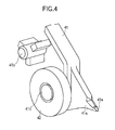
- FIG. 4 is an enlarged perspective view showing the separating claw end 41a of the separating claw unit 40 and its surroundings.
- the separating claw end 41a, the rotation fulcrum 41b, the guide roller 42, and the rotation center 41c of the guide roller 42 are provided on a lower part of the separating claw unit 40.
- the separating claw end 41a has an end surface 41e that contacts the heat roller 31.
- the end surface 41e has a small surface area. With such a configuration, toner is not likely to be deposited on the end surface 41e of the separating claw end 41a. Therefore, a surface and a back surface of the sheet P can be prevented from being smeared with the toner.
- FIG. 5 is a schematic view for illustrating a protruding amount of the lower end of the outer circumference of the guide roller 42 with respect to the above described line L0.
- the lower end of the outer circumference of the guide roller 42 protrudes downward from the straight line L0 connecting the nip portion 34 (as the contact area) of the fixing portion 30 and the nip portion 18d (as the contact area) of the conveying roller pair 18.
- the straight line L0 is defined by connecting a terminal point of the nip portion 34 between the heat roller 31 and the pressure roller 32 and a starting point of the nip portion 18d between the conveying roller 18a and the pinch roller 18b.
- the lower end of the outer circumference of the guide roller 42 protrudes downward from the straight line L0.
- the straight line L0 is defined by connecting the first contact point and the second contact point. If the heat roller 31 and the pressure roller 32 form the nip portion 34, and the conveying roller 18a and the pinch roller 18b form the nip portion 18d, the straight line L0 is defined by connecting the terminal point of the nip portion 34 and the starting point of the nip portion 18d.
- the straight line L0 is defined by connecting the terminal point of the nip portion 34 and the second contact point. If the heat roller 31 and the pressure roller 32 contact each other at the first contact point without forming the nip portion 34, and the conveying roller 18a and the pinch roller 18b form the nip portion 18d, the straight line L0 is defined by connecting the first contact point and the starting point of the nip portion 18d.
- the sheet P is fed out of the sheet cassette 11 by the pickup roller 12, and is further conveyed by the conveying roller 13, the retard roller 14 and the conveying roller pairs 15 and 16 to reach the image forming portion 17.
- the charging roller 17e uniformly charges the surface of the photosensitive drum 17c.
- the recording head 17b receives a printing job (sent from a host device) via a not shown control unit, and emits light to expose the surface of the photosensitive drum 17 in accordance with a printing pattern, so as to form a latent image on the surface of the photosensitive drum 17.
- the developing roller 17f is provided in contact with the photosensitive drum 17c, and causes the toner to adhere to the latent image on the surface of the photosensitive drum 17c so that a toner image is formed thereon.
- the toner image is transferred from the photosensitive drum 17c to the sheet P due to electric field between the photosensitive drum 17c and the transfer roller 17d. Then, the toner image is fixed to the sheet P by the fixing portion 30.
- the sheet P is ejected by the conveying roller pair 18 and the ejection roller pair 19 to the ejection tray 20.
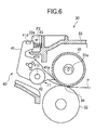
- FIG. 6 is a schematic view for illustrating a first state of the separating claw unit 40 during the passage of the sheet P through the fixing portion 30.
- the first state shown in FIG. 6 is a state after a leading end of the sheet P has passed the nip portion 34 between the heat roller 31 and the pressure roller 32, and just before the leading end of the sheet P reaches the guide roller 42.
- the leading end of the sheet P having passed the nip portion 34 passes a vicinity of the heat roller 31, and is conveyed along a vicinity of the separating claw end 41a.
- the separating claw end 41a contacts the heat roller 31 by the force F of the spring 43 as the biasing member, and therefore it is ensured that the sheet P is separated from the heat roller 31 and conveyed along the separating claw end 41a, even when the sheet P is thin and has a tendency to wind around the heat roller 31. In this state, the separating claw end 41a is kept in contact with the heat roller 31.
- a rotational friction force of the guide roller 42 and the separating claw unit 40 (about the rotation fulcrum 41b) is expressed as F1.
- a force of the spring 43 (as the biasing member) when the separating claw end 41a contacts the heat roller 31 is expressed as F2. It is preferable to satisfy the relationship F1 ⁇ F2.
- FIG. 7 is a schematic view for illustrating a second state of the separating claw unit 40 during the passage of the sheet P through the fixing portion 30.
- the second state shown in FIG. 7 is a state where the leading end of the sheet P contacts the guide roller 42.
- the separating claw unit 40 When the leading end of the sheet P (having been conveyed along the vicinity of the separating claw end 41a) contacts the guide roller 42, the separating claw unit 40 is forced by the sheet P, and rotates about the rotation fulcrum 41b resisting the force of the spring 43 so that the separating claw end 41a moves apart from the heat roller 31.
- a separating amount "t" between the separating claw end 41a and the heat roller 31 is determined by a position of the separating claw 41 when the separating claw projection 41d on the upper part of the separating claw 41 contacts the stopper 33a provided on the fixing portion cover 33 in the vicinity of the separating claw projection 41d.
- the separating amount "t” is determined so that the separating claw end 41a having reached a lower end of a movable range thereof does not contact the sheet P.
- the separating claw unit 40 When the leading end of the sheet P contacts the guide roller 42, the separating claw unit 40 is applied with a force F3 by the sheet P, and rotates clockwise.
- a biasing force i.e., a spring force
- F4 of the spring 43 exceeds the force F3 (i.e., F4 > F3)
- the separating claw 41 is brought into contact with the heat roller 31 due to the force F4 of the spring 43.
- the biasing force F4 is smaller than the force F3 (i.e., F4 ⁇ F3) until the separating claw projection 41d abuts against the stopper 33a.
- the force F3 i.e., F4 > F3
- the separating claw unit 40 is brought into contact with the heat roller 31 due to the biasing force F4 of the spring 43.
- the separating claw unit 40 rotates counterclockwise by the biasing force of the spring 43, so that the separating claw end 41a contacts the heat roller 31.
- the separating claw unit 40 operates in a similar manner as described above when the leading end of the sheet P (having been separated from the heat roller 31 by the separating claw end 41ad) contacts the guide roller 42.
- FIG. 8 is a schematic view showing a third state of the separating claw unit 40 during the passage of the sheet P through the fixing portion 30.
- the third state shown in FIG. 8 is a state where the guide roller 42 starts rotating clockwise by being forced by the sheet P and the leading end of the sheet P passes the guide roller 42, after the separating claw unit 40 has rotated to cause the separating claw unit end 41a to separate from the heat roller 31a.
- FIG. 9 is a schematic view showing a state where a jam of the sheet P occurs.
- the force causing the separating claw unit 40 to rotate clockwise disappears, and the separating claw end 41a contacts the heat roller 31 due to the biasing force of the spring 43 as shown in FIG. 8 .
- the separating claw end 41a remains apart from the heat roller 31 after the leading end of the sheet P has passed the guide roller 42, and if the sheet P is a thin sheet having a tendency to wind around the heat roller 31, a part (for example, other than the leading end) of the sheet P may enter into a gap between the separating claw end 41a and the heat roller 31, which may cause a jam or the like to occur.
- the separating claw end 41a contacts the heat roller 31 after the leading end of the sheet P has passed the guide roller 42 as shown in FIG. 8 , and therefore the occurrence of jam can be prevented.
- the first embodiment of the present invention provides the following advantages.
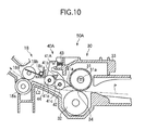
- FIG. 10 is a sectional view showing a configuration of a fixing device 50A according to the second embodiment of the present invention.
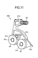
- FIG. 11 is a perspective view showing a separating claw unit 40A of the second embodiment.
- elements that are the same as those of the first embodiment are assigned the same reference numerals.
- the fixing device 50A of the second embodiment has substantially the same configuration as the fixing device 50 of the first embodiment.
- the separating claw unit 40A of the fixing device 50A of the second embodiment is different from the separating claw unit 40 of the first embodiment in that the separating claw unit 40A has a guide roller 44 in addition to the guide roller 42.
- the guide roller 44 is provided on downstream side of the guide roller 42 that guides the sheet P having been separated from the heat roller 31 by the separating claw end 41a having the same configuration as in the first embodiment.
- the separating claw unit 40A as a separating portion includes a separating claw 41A, the guide roller 42 as a first guide portion and the guide roller 44 as a second guide portion.
- the separating claw 41A includes a separating claw end 41a, a rotation fulcrum 41b, a rotation center 41c, a separating claw projection 41d and a rotation center 41e.
- the separating claw unit 40A as the separating portion is rotatable about the rotation fulcrum 41b with respect to the heat roller 31 of the fixing portion 30 as the carrying-out portion.
- the spring 43 as the biasing portion biases the separating claw unit 40A so that the separating claw unit 40A rotates in a direction in which the separating claw end 41a contacts the heat roller 31.
- the guide roller 42 as the first guide portion is rotatable about the rotation center 41c with respect to the separating claw unit 40A.
- the guide roller 44 as the second guide portion is rotatable about the rotation center 41e with respect to the separating claw unit 40A.
- the separating claw projection 41d is provided so as to abut against the stopper 33a to limit the rotation of the separating claw unit 40A in a direction in which the separating claw end 41a moves away from the heat roller 31.
- the rotation center 41c of the guide roller 41 is located on the heat roller 31 side with respect to the rotation fulcrum 41b, and is provided below the rotation fulcrum 41b of the separating claw 41. Further, a lower end of the outer circumference of the guide roller 42 protrudes downward from the straight line L0 (see, FIG. 5 ) connecting the nip portion 34 of the fixing portion 30 and the nip portion 18d of the conveying roller pair 18.
- the guide roller 44 is located between the rotation fulcrum 41b and the conveying roller pair 18, and below the rotation fulcrum 41b.
- the rotation center 41e of the guide roller 44 is located on downstream side of the guide roller 42.
- a lower end of the outer circumference of the guide roller 44 is located above a straight line L2 connecting the lower end of the outer circumference of the guide roller 42 and the nip portion 18d of the conveying roller pair 18. Further, the lower end of the outer circumference of the guide roller 44 is located below the rotation fulcrum 41b of the separating claw 41A, and is located on downstream side of the rotation fulcrum 41b of the separating claw 41A.
- the configuration of the fixing device 50A of the second embodiment is the same as the fixing device 50 of the first embodiment ( FIG. 2 ) except that the separating claw unit 40A has the guide roller 44.
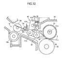
- FIG. 12 is a schematic view for illustrating a first state of the separating claw unit 40A during the passage of the sheet P through the fixing portion 30.
- the first state shown in FIG. 12 is a state after a leading end of the sheet P has passed the nip portion 34 between the heat roller 31 and the pressure roller 32, and just before the leading end of the sheet P reaches the guide roller 42.
- the leading end of the sheet P having passed the nip portion 34 may move relatively downward, depending on a material of the sheet P or a material of a surface layer of the pressure roller 32. In this case, the leading end of the sheet P passes a vicinity of the pressure roller 32, and is separated from the heat roller 31 by itself.
- the sheet P is conveyed along a conveying path guide 35 without contacting the separating claw end 41a. Even if the conveyed sheet P contacts the guide roller 42, the separating claw end 41a is kept in contact with the heat roller 31 since the guide roller 42 is forced in upward direction by the sheet P (i.e., the separating claw unit 40A does not rotate).
- FIG. 13 is a schematic view for illustrating a second state of the separating claw unit 40A during the passage of the sheet P through the fixing portion 30.
- the second state shown in FIG. 13 is a state where the leading end of the sheet P contacts the guide roller 44.
- the sheet P forces the guide roller 44 so that the separating claw unit 40A rotates clockwise about the rotation fulcrum 41b resisting the force of the spring 43. With the rotation of the separation claw unit 40A, the separating claw end 41a moves apart from the heat roller 31.
- a separating amount "t" between the separating claw end 41a and the heat roller 31 is determined by a position of the separating claw 41A when the separating claw projection 41d on the upper part of the separating claw 41A contacts the stopper 33a of the fixing portion cover 33d.
- the separating amount "t” is determined so that the separating claw end 41a having reached a lower end of a movable range thereof does not contact the sheet P.
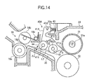
- FIG. 14 is a schematic view showing a third state of the separating claw unit 40A during the passage of the sheet P through the fixing portion 30.
- the third state shown in FIG. 14 is a state after the leading end of the sheet P reaches the conveying roller pair 18.
- the force causing the separating claw unit 40A to rotate clockwise disappears, since the guide roller 44 is located above the straight line L2 and does not contact the sheet P. Therefore, the separating claw unit 40A rotates to bring the separating claw end 41a in contact with the heat roller 31 due to the biasing force of the spring 43. Thereafter, the sheet P is conveyed by the conveying roller pair 18.
- the separating claw end 41a is kept in contact with the heat roller 31. Further, after a tail end of the sheet P has passed the separating claw unit 40A, the separating claw end 41a is kept in contact with the heat roller 31.
- the lower end of the outer circumference of the guide roller 44 is located above the straight line L2 connecting the lower end of the outer circumference of the guide roller 42 and the nip portion 18d (as the contact area) of the conveying roller pair 18 by an amount ⁇ S.
- the sheet P When the sheet P reaches the conveying roller pair 18, the sheet P is stretched between the nip portion 18d (as the contact area) of the conveying roller pair 18, the guide roller 42, and the nip portion 34 (as the contact area between the heat roller 31 and the pressure roller 32).
- a tensioning force of the sheet P acts on the separating claw unit 40A via the guide roller 42. Since the lower end of the outer circumference of the guide roller 42 is located above the straight line L2 connecting the lower end of the outer circumference of the guide roller 42 and the nip portion 18d of the conveying roller pair 18, the tensioning force of the stretched sheet P acts on the separating claw unit 40A only via the guide roller 42. Therefore, the tensioning force (i.e., an external force) acts on the guide roller 42 in a direction shown by an arrow X in FIG. 14 so that the separating claw end 41a contacts the heat roller 31.
- the tensioning force i.e., an external force
- FIG. 15 is a schematic view showing the positional relationship between the guide roller 42, the rotation fulcrum 41b of the separating claw 41A, and the guide roller 44.
- the guide roller 44 has a function to guide the sheet P toward the conveying roller pair 18, it is preferable that the guide roller 44 is located so as to contact the straight line L2. However, it is also necessary that the external force (i.e., the tensioning force) is applied to the separating claw unit 40A by the sheet P in a direction in which the separating claw end 41a contacts the heat roller 31 as described above.
- the external force i.e., the tensioning force
- the guide roller 42, the rotation fulcrum 41b and the guide roller 44 are arranged in this order along the conveying direction of the sheet P from upstream (i.e., the fixing portion 30 side) to downstream (i.e., conveying roller pair 18 side). Further, a distance m1 between the rotation center 41e of the guide roller 44 and the rotation fulcrum 41b is set to be smaller than a distance m2 between the rotation center 41c of the guide roller 42 and the rotation fulcrum 41b (i.e., m1 ⁇ m2).
- the distance m1 is a distance between the rotation center 41e and the rotation fulcrum 41b, which is projected onto the straight line L2 connecting the lower end of the outer circumference of the guide roller 42 and the nip portion 18d (as the contact area) of the conveying roller pair 18.
- the distance m2 is a distance between the rotation center 41c and the rotation fulcrum 41b, which is projected onto the straight line L2.
- the external force acting on the guide roller 42 is larger than the external force acting on the guide roller 44. Therefore, the external force acts on the separating claw unit 40A by the sheet P in a direction to cause the separating claw end 41a to contact the heat roller 31.
- the second embodiment of the present invention provides the following advantage in addition to the advantages of the first embodiment.
- the guide roller 42 and the guide roller 44 are provided at positions different from the rotation fulcrum 41b of the separating claw 41A, and the spring 43 generates the relatively small biasing force and allows the rotation of the separating claw unit 40 when the guide roller 42 is forced by the leading end of the sheet P.
- the separating claw end 41a can separates the sheet P from the heat roller 31, even when the sheet P does not wind around the heat roller 31, but the leading end of the sheet P moves relatively downward. As a result, the occurrence of jam of the sheet P can be prevented.
Landscapes
- Engineering & Computer Science (AREA)
- Mechanical Engineering (AREA)
- Physics & Mathematics (AREA)
- General Physics & Mathematics (AREA)
- Fixing For Electrophotography (AREA)
- Separation, Sorting, Adjustment, Or Bending Of Sheets To Be Conveyed (AREA)
Applications Claiming Priority (1)
| Application Number | Priority Date | Filing Date | Title |
|---|---|---|---|
| JP2010061375A JP5412337B2 (ja) | 2010-03-17 | 2010-03-17 | 分離装置、定着装置、媒体搬送装置、及び画像形成装置 |
Publications (3)
| Publication Number | Publication Date |
|---|---|
| EP2366646A2 true EP2366646A2 (de) | 2011-09-21 |
| EP2366646A3 EP2366646A3 (de) | 2013-03-27 |
| EP2366646B1 EP2366646B1 (de) | 2015-12-16 |
Family
ID=44117315
Family Applications (1)
| Application Number | Title | Priority Date | Filing Date |
|---|---|---|---|
| EP11157941.3A Not-in-force EP2366646B1 (de) | 2010-03-17 | 2011-03-11 | Trennvorrichtung, Fixiervorrichtung, Medienübertragungsvorrichtung und Bilderzeugungsvorrichtung |
Country Status (4)
| Country | Link |
|---|---|
| US (1) | US8602414B2 (de) |
| EP (1) | EP2366646B1 (de) |
| JP (1) | JP5412337B2 (de) |
| CN (1) | CN102190167B (de) |
Cited By (1)
| Publication number | Priority date | Publication date | Assignee | Title |
|---|---|---|---|---|
| WO2020076496A1 (en) * | 2018-10-08 | 2020-04-16 | Eastman Kodak Company | Fuser stripping mechanism with beveled tip |
Families Citing this family (11)
| Publication number | Priority date | Publication date | Assignee | Title |
|---|---|---|---|---|
| JP5348638B2 (ja) * | 2010-12-15 | 2013-11-20 | 京セラドキュメントソリューションズ株式会社 | クリーニング装置及びこのクリーニング装置を備えた画像形成装置 |
| JP5915879B2 (ja) * | 2011-06-30 | 2016-05-11 | 株式会社リコー | 定着装置及び画像形成装置 |
| JP5831321B2 (ja) * | 2012-03-23 | 2015-12-09 | 沖電気工業株式会社 | 媒体収納繰出装置及び媒体取引装置 |
| JP5740369B2 (ja) * | 2012-08-29 | 2015-06-24 | 京セラドキュメントソリューションズ株式会社 | シート搬送装置、およびこれを備えた画像形成装置 |
| US20150117920A1 (en) * | 2013-10-28 | 2015-04-30 | Canon Kabushiki Kaisha | Image forming apparatus |
| US9323195B2 (en) | 2014-04-25 | 2016-04-26 | Oki Data Corporation | Fixing device and image forming apparatus |
| JP5992062B2 (ja) * | 2015-02-23 | 2016-09-14 | 京セラドキュメントソリューションズ株式会社 | 定着装置及び該定着装置を備えた画像形成装置 |
| JP6686937B2 (ja) | 2017-03-01 | 2020-04-22 | 京セラドキュメントソリューションズ株式会社 | 定着装置及び画像形成装置 |
| US10509345B1 (en) * | 2018-06-15 | 2019-12-17 | Fuji Xerox Co., Ltd. | Image forming apparatus for correcting curl of paper |
| JP2021067865A (ja) * | 2019-10-25 | 2021-04-30 | 富士ゼロックス株式会社 | カール補正装置及びこれを用いた画像形成装置 |
| JP2023031851A (ja) * | 2021-08-25 | 2023-03-09 | 富士フイルムビジネスイノベーション株式会社 | 定着装置、画像形成装置 |
Citations (1)
| Publication number | Priority date | Publication date | Assignee | Title |
|---|---|---|---|---|
| JP2006126876A (ja) | 2006-02-06 | 2006-05-18 | Oki Data Corp | 定着装置 |
Family Cites Families (14)
| Publication number | Priority date | Publication date | Assignee | Title |
|---|---|---|---|---|
| JPS57124772A (en) * | 1981-01-27 | 1982-08-03 | Canon Inc | Peeling device |
| JP2841639B2 (ja) * | 1990-02-22 | 1998-12-24 | 富士ゼロックス株式会社 | 画像形成装置の用紙剥離装置 |
| JP3073577B2 (ja) * | 1991-11-13 | 2000-08-07 | 京セラミタ株式会社 | 用紙分離爪 |
| US5392108A (en) * | 1993-11-22 | 1995-02-21 | Xerox Corporation | Stripping device |
| JP3923670B2 (ja) * | 1998-11-20 | 2007-06-06 | 株式会社沖データ | 定着装置 |
| JP3862914B2 (ja) * | 2000-02-23 | 2006-12-27 | 株式会社リコー | 定着装置 |
| JP2004170905A (ja) * | 2002-10-29 | 2004-06-17 | Sharp Corp | 用紙剥離機構およびプロセスカートリッジ |
| JP4561317B2 (ja) * | 2004-11-04 | 2010-10-13 | 村田機械株式会社 | 画像形成装置 |
| US7613421B2 (en) * | 2005-08-31 | 2009-11-03 | Kyocera Mita Corporation | Fixing device and image forming apparatus |
| JP4701955B2 (ja) * | 2005-09-22 | 2011-06-15 | 富士ゼロックス株式会社 | 画像形成装置 |
| US7486922B2 (en) * | 2005-11-22 | 2009-02-03 | Kyocera Mita Corporation | Fixing device and image forming apparatus with separating mechanism pivotable about plural axes |
| CN100476632C (zh) * | 2005-11-22 | 2009-04-08 | 京瓷美达株式会社 | 定影装置和图像形成装置 |
| JP2008111906A (ja) * | 2006-10-30 | 2008-05-15 | Seiko Epson Corp | 定着装置、それを用いた画像形成装置及び定着方法 |
| JP4884264B2 (ja) * | 2007-03-09 | 2012-02-29 | 株式会社リコー | 分離装置、定着装置、及び、画像形成装置 |
-
2010
- 2010-03-17 JP JP2010061375A patent/JP5412337B2/ja not_active Expired - Fee Related
-
2011
- 2011-03-11 EP EP11157941.3A patent/EP2366646B1/de not_active Not-in-force
- 2011-03-16 US US13/064,292 patent/US8602414B2/en not_active Expired - Fee Related
- 2011-03-17 CN CN201110071721.8A patent/CN102190167B/zh not_active Expired - Fee Related
Patent Citations (1)
| Publication number | Priority date | Publication date | Assignee | Title |
|---|---|---|---|---|
| JP2006126876A (ja) | 2006-02-06 | 2006-05-18 | Oki Data Corp | 定着装置 |
Cited By (1)
| Publication number | Priority date | Publication date | Assignee | Title |
|---|---|---|---|---|
| WO2020076496A1 (en) * | 2018-10-08 | 2020-04-16 | Eastman Kodak Company | Fuser stripping mechanism with beveled tip |
Also Published As
| Publication number | Publication date |
|---|---|
| JP5412337B2 (ja) | 2014-02-12 |
| EP2366646A3 (de) | 2013-03-27 |
| JP2011197133A (ja) | 2011-10-06 |
| EP2366646B1 (de) | 2015-12-16 |
| CN102190167B (zh) | 2016-04-20 |
| US8602414B2 (en) | 2013-12-10 |
| CN102190167A (zh) | 2011-09-21 |
| US20110227273A1 (en) | 2011-09-22 |
Similar Documents
| Publication | Publication Date | Title |
|---|---|---|
| EP2366646B1 (de) | Trennvorrichtung, Fixiervorrichtung, Medienübertragungsvorrichtung und Bilderzeugungsvorrichtung | |
| US7620356B2 (en) | Fixing apparatus and image forming apparatus having the same | |
| JPH08157107A (ja) | 給紙装置 | |
| US12265345B2 (en) | Image forming apparatus | |
| US11619902B2 (en) | Conveyance control for image forming apparatus | |
| JP5146005B2 (ja) | 定着装置及び画像形成装置 | |
| CN102314138A (zh) | 片材分离机构和图像形成设备 | |
| US10647538B2 (en) | Sheet discharge device and image forming apparatus therewith | |
| JP2003255750A (ja) | 定着装置および画像形成装置 | |
| JP4002585B2 (ja) | 定着装置 | |
| JP3591976B2 (ja) | 画像形成装置 | |
| US8699072B2 (en) | Image forming apparatus | |
| JP5025523B2 (ja) | 画像形成装置 | |
| JP2002123096A (ja) | 画像形成装置 | |
| US20260086487A1 (en) | Paper feeding device and image forming apparatus | |
| US20240427278A1 (en) | Image forming apparatus | |
| JP2009007087A (ja) | 画像形成装置 | |
| JP2003107815A (ja) | 画像形成装置 | |
| JP4569907B2 (ja) | 媒体搬送装置及び画像形成装置 | |
| JP4065509B2 (ja) | シート供給装置、画像形成装置及び画像読取装置 | |
| JP2006131348A (ja) | シート搬送装置及び画像形成装置 | |
| JPH1115221A (ja) | 画像形成装置 | |
| JP2003237982A (ja) | 電子写真装置 | |
| JP2000062988A (ja) | シート分離装置及び画像形成装置 | |
| JP2002249257A (ja) | 画像形成装置 |
Legal Events
| Date | Code | Title | Description |
|---|---|---|---|
| PUAI | Public reference made under article 153(3) epc to a published international application that has entered the european phase |
Free format text: ORIGINAL CODE: 0009012 |
|
| AK | Designated contracting states |
Kind code of ref document: A2 Designated state(s): AL AT BE BG CH CY CZ DE DK EE ES FI FR GB GR HR HU IE IS IT LI LT LU LV MC MK MT NL NO PL PT RO RS SE SI SK SM TR |
|
| AX | Request for extension of the european patent |
Extension state: BA ME |
|
| PUAL | Search report despatched |
Free format text: ORIGINAL CODE: 0009013 |
|
| AK | Designated contracting states |
Kind code of ref document: A3 Designated state(s): AL AT BE BG CH CY CZ DE DK EE ES FI FR GB GR HR HU IE IS IT LI LT LU LV MC MK MT NL NO PL PT RO RS SE SI SK SM TR |
|
| AX | Request for extension of the european patent |
Extension state: BA ME |
|
| RIC1 | Information provided on ipc code assigned before grant |
Ipc: B65H 5/36 20060101AFI20130219BHEP Ipc: G03G 15/20 20060101ALI20130219BHEP |
|
| 17P | Request for examination filed |
Effective date: 20130903 |
|
| RBV | Designated contracting states (corrected) |
Designated state(s): AL AT BE BG CH CY CZ DE DK EE ES FI FR GB GR HR HU IE IS IT LI LT LU LV MC MK MT NL NO PL PT RO RS SE SI SK SM TR |
|
| GRAP | Despatch of communication of intention to grant a patent |
Free format text: ORIGINAL CODE: EPIDOSNIGR1 |
|
| INTG | Intention to grant announced |
Effective date: 20150622 |
|
| GRAS | Grant fee paid |
Free format text: ORIGINAL CODE: EPIDOSNIGR3 |
|
| GRAA | (expected) grant |
Free format text: ORIGINAL CODE: 0009210 |
|
| AK | Designated contracting states |
Kind code of ref document: B1 Designated state(s): AL AT BE BG CH CY CZ DE DK EE ES FI FR GB GR HR HU IE IS IT LI LT LU LV MC MK MT NL NO PL PT RO RS SE SI SK SM TR |
|
| REG | Reference to a national code |
Ref country code: GB Ref legal event code: FG4D |
|
| REG | Reference to a national code |
Ref country code: CH Ref legal event code: EP |
|
| REG | Reference to a national code |
Ref country code: IE Ref legal event code: FG4D |
|
| REG | Reference to a national code |
Ref country code: AT Ref legal event code: REF Ref document number: 765450 Country of ref document: AT Kind code of ref document: T Effective date: 20160115 |
|
| REG | Reference to a national code |
Ref country code: DE Ref legal event code: R096 Ref document number: 602011021968 Country of ref document: DE |
|
| REG | Reference to a national code |
Ref country code: FR Ref legal event code: PLFP Year of fee payment: 6 |
|
| REG | Reference to a national code |
Ref country code: NL Ref legal event code: FP |
|
| REG | Reference to a national code |
Ref country code: LT Ref legal event code: MG4D |
|
| PG25 | Lapsed in a contracting state [announced via postgrant information from national office to epo] |
Ref country code: LT Free format text: LAPSE BECAUSE OF FAILURE TO SUBMIT A TRANSLATION OF THE DESCRIPTION OR TO PAY THE FEE WITHIN THE PRESCRIBED TIME-LIMIT Effective date: 20151216 Ref country code: HR Free format text: LAPSE BECAUSE OF FAILURE TO SUBMIT A TRANSLATION OF THE DESCRIPTION OR TO PAY THE FEE WITHIN THE PRESCRIBED TIME-LIMIT Effective date: 20151216 Ref country code: NO Free format text: LAPSE BECAUSE OF FAILURE TO SUBMIT A TRANSLATION OF THE DESCRIPTION OR TO PAY THE FEE WITHIN THE PRESCRIBED TIME-LIMIT Effective date: 20160316 |
|
| REG | Reference to a national code |
Ref country code: AT Ref legal event code: MK05 Ref document number: 765450 Country of ref document: AT Kind code of ref document: T Effective date: 20151216 |
|
| PG25 | Lapsed in a contracting state [announced via postgrant information from national office to epo] |
Ref country code: GR Free format text: LAPSE BECAUSE OF FAILURE TO SUBMIT A TRANSLATION OF THE DESCRIPTION OR TO PAY THE FEE WITHIN THE PRESCRIBED TIME-LIMIT Effective date: 20160317 Ref country code: LV Free format text: LAPSE BECAUSE OF FAILURE TO SUBMIT A TRANSLATION OF THE DESCRIPTION OR TO PAY THE FEE WITHIN THE PRESCRIBED TIME-LIMIT Effective date: 20151216 Ref country code: FI Free format text: LAPSE BECAUSE OF FAILURE TO SUBMIT A TRANSLATION OF THE DESCRIPTION OR TO PAY THE FEE WITHIN THE PRESCRIBED TIME-LIMIT Effective date: 20151216 Ref country code: RS Free format text: LAPSE BECAUSE OF FAILURE TO SUBMIT A TRANSLATION OF THE DESCRIPTION OR TO PAY THE FEE WITHIN THE PRESCRIBED TIME-LIMIT Effective date: 20151216 Ref country code: SE Free format text: LAPSE BECAUSE OF FAILURE TO SUBMIT A TRANSLATION OF THE DESCRIPTION OR TO PAY THE FEE WITHIN THE PRESCRIBED TIME-LIMIT Effective date: 20151216 |
|
| PG25 | Lapsed in a contracting state [announced via postgrant information from national office to epo] |
Ref country code: IT Free format text: LAPSE BECAUSE OF FAILURE TO SUBMIT A TRANSLATION OF THE DESCRIPTION OR TO PAY THE FEE WITHIN THE PRESCRIBED TIME-LIMIT Effective date: 20151216 Ref country code: ES Free format text: LAPSE BECAUSE OF FAILURE TO SUBMIT A TRANSLATION OF THE DESCRIPTION OR TO PAY THE FEE WITHIN THE PRESCRIBED TIME-LIMIT Effective date: 20151216 Ref country code: CZ Free format text: LAPSE BECAUSE OF FAILURE TO SUBMIT A TRANSLATION OF THE DESCRIPTION OR TO PAY THE FEE WITHIN THE PRESCRIBED TIME-LIMIT Effective date: 20151216 |
|
| PG25 | Lapsed in a contracting state [announced via postgrant information from national office to epo] |
Ref country code: AT Free format text: LAPSE BECAUSE OF FAILURE TO SUBMIT A TRANSLATION OF THE DESCRIPTION OR TO PAY THE FEE WITHIN THE PRESCRIBED TIME-LIMIT Effective date: 20151216 Ref country code: BE Free format text: LAPSE BECAUSE OF NON-PAYMENT OF DUE FEES Effective date: 20160331 Ref country code: SM Free format text: LAPSE BECAUSE OF FAILURE TO SUBMIT A TRANSLATION OF THE DESCRIPTION OR TO PAY THE FEE WITHIN THE PRESCRIBED TIME-LIMIT Effective date: 20151216 Ref country code: SK Free format text: LAPSE BECAUSE OF FAILURE TO SUBMIT A TRANSLATION OF THE DESCRIPTION OR TO PAY THE FEE WITHIN THE PRESCRIBED TIME-LIMIT Effective date: 20151216 Ref country code: EE Free format text: LAPSE BECAUSE OF FAILURE TO SUBMIT A TRANSLATION OF THE DESCRIPTION OR TO PAY THE FEE WITHIN THE PRESCRIBED TIME-LIMIT Effective date: 20151216 Ref country code: PT Free format text: LAPSE BECAUSE OF FAILURE TO SUBMIT A TRANSLATION OF THE DESCRIPTION OR TO PAY THE FEE WITHIN THE PRESCRIBED TIME-LIMIT Effective date: 20160418 Ref country code: RO Free format text: LAPSE BECAUSE OF FAILURE TO SUBMIT A TRANSLATION OF THE DESCRIPTION OR TO PAY THE FEE WITHIN THE PRESCRIBED TIME-LIMIT Effective date: 20151216 Ref country code: IS Free format text: LAPSE BECAUSE OF FAILURE TO SUBMIT A TRANSLATION OF THE DESCRIPTION OR TO PAY THE FEE WITHIN THE PRESCRIBED TIME-LIMIT Effective date: 20160416 |
|
| REG | Reference to a national code |
Ref country code: DE Ref legal event code: R097 Ref document number: 602011021968 Country of ref document: DE |
|
| PLBE | No opposition filed within time limit |
Free format text: ORIGINAL CODE: 0009261 |
|
| STAA | Information on the status of an ep patent application or granted ep patent |
Free format text: STATUS: NO OPPOSITION FILED WITHIN TIME LIMIT |
|
| PG25 | Lapsed in a contracting state [announced via postgrant information from national office to epo] |
Ref country code: MC Free format text: LAPSE BECAUSE OF FAILURE TO SUBMIT A TRANSLATION OF THE DESCRIPTION OR TO PAY THE FEE WITHIN THE PRESCRIBED TIME-LIMIT Effective date: 20151216 Ref country code: DK Free format text: LAPSE BECAUSE OF FAILURE TO SUBMIT A TRANSLATION OF THE DESCRIPTION OR TO PAY THE FEE WITHIN THE PRESCRIBED TIME-LIMIT Effective date: 20151216 Ref country code: PL Free format text: LAPSE BECAUSE OF FAILURE TO SUBMIT A TRANSLATION OF THE DESCRIPTION OR TO PAY THE FEE WITHIN THE PRESCRIBED TIME-LIMIT Effective date: 20151216 Ref country code: LU Free format text: LAPSE BECAUSE OF FAILURE TO SUBMIT A TRANSLATION OF THE DESCRIPTION OR TO PAY THE FEE WITHIN THE PRESCRIBED TIME-LIMIT Effective date: 20160311 |
|
| REG | Reference to a national code |
Ref country code: CH Ref legal event code: PL |
|
| 26N | No opposition filed |
Effective date: 20160919 |
|
| REG | Reference to a national code |
Ref country code: IE Ref legal event code: MM4A |
|
| PG25 | Lapsed in a contracting state [announced via postgrant information from national office to epo] |
Ref country code: BE Free format text: LAPSE BECAUSE OF FAILURE TO SUBMIT A TRANSLATION OF THE DESCRIPTION OR TO PAY THE FEE WITHIN THE PRESCRIBED TIME-LIMIT Effective date: 20151216 |
|
| PG25 | Lapsed in a contracting state [announced via postgrant information from national office to epo] |
Ref country code: CH Free format text: LAPSE BECAUSE OF NON-PAYMENT OF DUE FEES Effective date: 20160331 Ref country code: LI Free format text: LAPSE BECAUSE OF NON-PAYMENT OF DUE FEES Effective date: 20160331 Ref country code: IE Free format text: LAPSE BECAUSE OF NON-PAYMENT OF DUE FEES Effective date: 20160311 |
|
| REG | Reference to a national code |
Ref country code: FR Ref legal event code: PLFP Year of fee payment: 7 |
|
| PG25 | Lapsed in a contracting state [announced via postgrant information from national office to epo] |
Ref country code: SI Free format text: LAPSE BECAUSE OF FAILURE TO SUBMIT A TRANSLATION OF THE DESCRIPTION OR TO PAY THE FEE WITHIN THE PRESCRIBED TIME-LIMIT Effective date: 20151216 |
|
| PGFP | Annual fee paid to national office [announced via postgrant information from national office to epo] |
Ref country code: DE Payment date: 20170307 Year of fee payment: 7 Ref country code: FR Payment date: 20170213 Year of fee payment: 7 |
|
| PGFP | Annual fee paid to national office [announced via postgrant information from national office to epo] |
Ref country code: NL Payment date: 20170210 Year of fee payment: 7 Ref country code: GB Payment date: 20170308 Year of fee payment: 7 |
|
| PG25 | Lapsed in a contracting state [announced via postgrant information from national office to epo] |
Ref country code: MT Free format text: LAPSE BECAUSE OF FAILURE TO SUBMIT A TRANSLATION OF THE DESCRIPTION OR TO PAY THE FEE WITHIN THE PRESCRIBED TIME-LIMIT Effective date: 20151216 |
|
| PG25 | Lapsed in a contracting state [announced via postgrant information from national office to epo] |
Ref country code: HU Free format text: LAPSE BECAUSE OF FAILURE TO SUBMIT A TRANSLATION OF THE DESCRIPTION OR TO PAY THE FEE WITHIN THE PRESCRIBED TIME-LIMIT; INVALID AB INITIO Effective date: 20110311 Ref country code: CY Free format text: LAPSE BECAUSE OF FAILURE TO SUBMIT A TRANSLATION OF THE DESCRIPTION OR TO PAY THE FEE WITHIN THE PRESCRIBED TIME-LIMIT Effective date: 20151216 |
|
| PG25 | Lapsed in a contracting state [announced via postgrant information from national office to epo] |
Ref country code: MK Free format text: LAPSE BECAUSE OF FAILURE TO SUBMIT A TRANSLATION OF THE DESCRIPTION OR TO PAY THE FEE WITHIN THE PRESCRIBED TIME-LIMIT Effective date: 20151216 Ref country code: TR Free format text: LAPSE BECAUSE OF FAILURE TO SUBMIT A TRANSLATION OF THE DESCRIPTION OR TO PAY THE FEE WITHIN THE PRESCRIBED TIME-LIMIT Effective date: 20151216 Ref country code: MT Free format text: LAPSE BECAUSE OF FAILURE TO SUBMIT A TRANSLATION OF THE DESCRIPTION OR TO PAY THE FEE WITHIN THE PRESCRIBED TIME-LIMIT Effective date: 20160331 |
|
| PG25 | Lapsed in a contracting state [announced via postgrant information from national office to epo] |
Ref country code: BG Free format text: LAPSE BECAUSE OF FAILURE TO SUBMIT A TRANSLATION OF THE DESCRIPTION OR TO PAY THE FEE WITHIN THE PRESCRIBED TIME-LIMIT Effective date: 20151216 |
|
| REG | Reference to a national code |
Ref country code: DE Ref legal event code: R119 Ref document number: 602011021968 Country of ref document: DE |
|
| PG25 | Lapsed in a contracting state [announced via postgrant information from national office to epo] |
Ref country code: AL Free format text: LAPSE BECAUSE OF FAILURE TO SUBMIT A TRANSLATION OF THE DESCRIPTION OR TO PAY THE FEE WITHIN THE PRESCRIBED TIME-LIMIT Effective date: 20151216 |
|
| REG | Reference to a national code |
Ref country code: NL Ref legal event code: MM Effective date: 20180401 |
|
| GBPC | Gb: european patent ceased through non-payment of renewal fee |
Effective date: 20180311 |
|
| PG25 | Lapsed in a contracting state [announced via postgrant information from national office to epo] |
Ref country code: NL Free format text: LAPSE BECAUSE OF NON-PAYMENT OF DUE FEES Effective date: 20180401 |
|
| PG25 | Lapsed in a contracting state [announced via postgrant information from national office to epo] |
Ref country code: DE Free format text: LAPSE BECAUSE OF NON-PAYMENT OF DUE FEES Effective date: 20181002 |
|
| PG25 | Lapsed in a contracting state [announced via postgrant information from national office to epo] |
Ref country code: GB Free format text: LAPSE BECAUSE OF NON-PAYMENT OF DUE FEES Effective date: 20180311 |
|
| PG25 | Lapsed in a contracting state [announced via postgrant information from national office to epo] |
Ref country code: FR Free format text: LAPSE BECAUSE OF NON-PAYMENT OF DUE FEES Effective date: 20180331 |