EP2365179A2 - Ganzglasfassade - Google Patents
Ganzglasfassade Download PDFInfo
- Publication number
- EP2365179A2 EP2365179A2 EP11155830A EP11155830A EP2365179A2 EP 2365179 A2 EP2365179 A2 EP 2365179A2 EP 11155830 A EP11155830 A EP 11155830A EP 11155830 A EP11155830 A EP 11155830A EP 2365179 A2 EP2365179 A2 EP 2365179A2
- Authority
- EP
- European Patent Office
- Prior art keywords
- glass
- facade
- support structure
- surface elements
- gap
- Prior art date
- Legal status (The legal status is an assumption and is not a legal conclusion. Google has not performed a legal analysis and makes no representation as to the accuracy of the status listed.)
- Granted
Links
Images



Classifications
-
- E—FIXED CONSTRUCTIONS
- E06—DOORS, WINDOWS, SHUTTERS, OR ROLLER BLINDS IN GENERAL; LADDERS
- E06B—FIXED OR MOVABLE CLOSURES FOR OPENINGS IN BUILDINGS, VEHICLES, FENCES OR LIKE ENCLOSURES IN GENERAL, e.g. DOORS, WINDOWS, BLINDS, GATES
- E06B3/00—Window sashes, door leaves, or like elements for closing wall or like openings; Layout of fixed or moving closures, e.g. windows in wall or like openings; Features of rigidly-mounted outer frames relating to the mounting of wing frames
- E06B3/54—Fixing of glass panes or like plates
- E06B3/5427—Fixing of glass panes or like plates the panes mounted flush with the surrounding frame or with the surrounding panes
-
- E—FIXED CONSTRUCTIONS
- E06—DOORS, WINDOWS, SHUTTERS, OR ROLLER BLINDS IN GENERAL; LADDERS
- E06B—FIXED OR MOVABLE CLOSURES FOR OPENINGS IN BUILDINGS, VEHICLES, FENCES OR LIKE ENCLOSURES IN GENERAL, e.g. DOORS, WINDOWS, BLINDS, GATES
- E06B5/00—Doors, windows, or like closures for special purposes; Border constructions therefor
- E06B5/10—Doors, windows, or like closures for special purposes; Border constructions therefor for protection against air-raid or other war-like action; for other protective purposes
- E06B5/11—Doors, windows, or like closures for special purposes; Border constructions therefor for protection against air-raid or other war-like action; for other protective purposes against burglary
- E06B5/116—Arrangements preventing the removal of glazing panels
Definitions
- the present invention relates to an all-glass facade according to the preamble of claim 1.
- An all-glass facade essentially comprises a facade support structure and a number of surface elements held by the facade support structure by means of glass holders.
- the façade support structure comprises substantially horizontal posts and vertical bars.
- the bar and the post are essentially elongated aluminum hollow profiles.
- other materials or profile shapes are conceivable here.
- the glass holders In an assembled state, the glass holders extend perpendicularly from the post and are arranged in a gap between two surface elements.
- the gap is only partially filled by the glass holder, in particular the directed to the front of the glass facade gap is filled with a silicone layer and / or a decorative band, in particular to maintain an attractive appearance.
- shut-off profiles are provided which completely or at least largely seal the gap.
- All-glass facades according to the prior art as for example from the DE 36 24 491 C3 have become known, do not provide sufficient protection here.
- the gap and thus the surface elements substantially supporting elements are accessible by the backing tape deducted or the silicone layer is removed. This can be done for example by lever tools or similar tools.
- an at least partially U-shaped shut-off profile is used.
- the U-shaped Absperrprofil has in cross section corresponding to a base side and two legs.
- the base is connected, for example with screws, with the facade support structure and the legs are arranged parallel or substantially parallel to the side surfaces of the respective surface elements.
- the gap can also be filled or closed, for example, with silicone or a cover band.
- the all-glass façade according to the invention has no other appearance than an all-glass façade designated from the prior art.
- the all-glass façade according to the invention is substantially more burglar-proof, since the essential elements carrying the surface elements are not accessible even after the removal of the silicone layer or the cover strip.
- a surface element for example, not easily be removed with a lever tool - at least the levering of a surface element is considerably more difficult.
- the Absperrprofil only partially a U-shaped cross section and sections has an L-shaped cross section or is formed in sections as a flat profile.
- Such configured Absperrprofil can be optimally adapted to the conditions in the gap.
- Another measure to increase burglar resistance can be, for example, that the Absperrprofil is connected by means of at least one screw with the facade support structure and / or with the at least one glass holder and / or with the at least one insulating profile, in particular the head of at least one Screw is made unusable after assembly.
- An all-glass façade according to the invention essentially comprises a facade support structure, at least one, preferably a plurality, glass holders 5 and a number of surface elements 3.
- the facade support structure faces a wall, in particular a house wall, whereas the Surface elements are arranged in front of the facade support structure.
- the surface elements are preferably laminated glass panes. Other surface elements, such as plastic plates, steel plates, panels, etc. are conceivable.
- the façade support structure essentially comprises posts 1 and bars 2.
- the posts 1 are elongated aluminum hollow profiles which are vertically aligned and upside down in a conventional mounting position.
- the bars 2 are elongated aluminum hollow profiles, which are aligned horizontally in a conventional mounting position. Of course, other materials or profile shapes are conceivable here.
- the posts 1 and 2 bars are assembled into a grid-like facade support structure with approximately square or rectangular openings.
- the surface elements 3 are arranged substantially in front of the openings of the facade support structure. For sealing and support of the surface elements 3 on the facade support structure seals 4 are provided.
- the glass holder 5 has two wings 51 and a shaft 52.
- the shaft 52 is connected at the end to the facade support structure.
- the wings 51 are provided, which extend substantially perpendicularly from the shaft 52.
- the glass holder 5 is preferably a cross-sectionally approximately T- or L-shaped metal profile with plastic cap.
- the glass holders 5 used are connected on the one hand to the facade support structure and on the other hand to the respective surface elements 3.
- two side surfaces 31 face the aforementioned surface elements 3 and form a gap 6 between them.
- this gap 6 protrude, in addition to the glass holders 5, and insulating profiles 7.
- These are profiles of foam or plastic with hollow chambers, which are also attached to the facade support structure.
- the insulating profiles 7 can be mounted between the longitudinally spaced glass holders 5, depending on the requirements of the thermal insulation. In principle, however, can also be dispensed with the insulating profiles 7, if, for example, no special requirements are made of the thermal insulation.
- the aforementioned gap 6 is - if no Kaschieruß be made - visible to a viewer of the all-glass facade.
- this gap 6 is closed at least with silicone 9 or similar fillers.
- a shut-off profile A, 8 is provided, which is attached to the at least one glass holder 5 and extends at least over the width of the gap 6.
- the Absperrprofil A, 8 is an elongated Absperrprofil, which, if a plurality of glass holder 5 are mounted in the gap 6, is connected to each glass holder 5.
- the Absperrprofil A, 8 extends correspondingly over the length of the gap 6.
- the Absperrprofil A, 8 is aligned substantially parallel to the posts 1 and 2 bars.
- the Absperrprofil 8 is at least partially formed in cross-section U-shaped, in particular therefore has a base 81 and two legs 82.
- this configuration of the shut-off profile 8 it is furthermore possible to seal the gap 6 in such a way that no silicone 9 reaches the area of the glass holder 5 or insulating profiles 7.
- an inventive Absperrprofil 8 allows access to the glass holders 5 and Dämmprofilen 7 and also to the side surfaces 31 of the surface elements 3 to block, even if the silicone 9 has been removed. For this purpose, prevent the legs 82 of the cross-sectionally U-shaped Absperrprofils 8 that a tool can pass without authorization in the area of the glass holder 5.
- the shut-off profile 8 is an elongate, in cross-section U-shaped aluminum profile. Conceivable, of course, other materials, such as steel or plastic. Also, the Absperrprofil 8 only partially a U-shaped cross-section and partially have a different cross-section, for example, an L-shaped cross-section. In particular, with the latter embodiment of the Absperrprofils 8 can be a very selective burglar protection exclusively in the glass holder. 5 be made.
- the insulating profiles 7 may for example be covered only by the L-shaped cross-section. Also, such Absperrprofil 8 may be adapted to different gaps.
- the U-shaped shut-off profile 8 is connected in a particularly robust manner to the facade support structure, in particular the respective post 1 or the bar 2, and / or the glass holder 5 and / or the insulating profile 7.
- at least one screw 10 is provided, which is inserted through a bore 83 of the U-shaped Absperrprofils 8 and through a corresponding through hole 53 of the glass holder 5 and / or through hole 71 of the insulating profile 7 and into a bore or thread groove 11 of the post 1 or 2 bar is screwed in.
- the head of the at least one screw 10 is rendered unusable after assembly. This can be done, for example, by selecting a head with an Allen key or Torx hole, with the Allen key or Torx hole being drilled out after assembly.
Landscapes
- Engineering & Computer Science (AREA)
- Civil Engineering (AREA)
- Structural Engineering (AREA)
- Load-Bearing And Curtain Walls (AREA)
Abstract
Description
- Die vorliegende Erfindung betrifft eine Ganzglasfassade gemäß dem Oberbegriff des Anspruchs 1.
- Eine Ganzglasfassade umfasst im Wesentlichen eine Fassaden-Trägerkonstruktion und eine Anzahl von Flächenelementen, die von der Fassaden-Trägerkonstruktion mittels Glashaltern gehalten werden.
- Die Fassaden-Trägerkonstruktion umfasst wiederum im Wesentlichen horizontale Pfosten und vertikale Riegel. Bei dem Riegel und dem Pfosten handelt es sich im Wesentlichen um längliche Aluminiumhohlprofile. Selbstverständlich sind hier andere Materialien bzw. Profilformen denkbar.
- In einem montierten Zustand erstrecken sich die Glashalter senkrecht von dem Pfosten bzw. Riegel und sind in einem Spalt zwischen zwei Flächenelementen angeordnet. Der Spalt wird nur abschnittsweise von dem Glashalter ausgefüllt, insbesondere der zur Vorderseite der Glasfassade gerichtete Spalt ist mit einer Silikonschicht und/oder einem Vorlegeband ausgefüllt, insbesondere um eine ansprechende Optik zu wahren. Um zu verhindern, dass Silikon während der Montage in den Bereich der Glashalter bzw. der Fassaden-Trägerkonstruktion gelangt, sind Absperrprofile vorgesehen, die den Spalt vollständig oder zumindest weitestgehend abdichten.
- Eine Anforderung an eine Ganzglasfassade besteht darin, dass sie einen Schutz gegen Einbruch bieten soll. Ganzglasfassaden gemäß dem Stand der Technik, wie sie beispielsweise aus der
DE 36 24 491 C3 bekannt geworden sind, bieten hier keinen ausreichenden Schutz. Der Spalt und damit die die Flächenelemente wesentlich tragenden Elemente, sind dadurch zugänglich, dass das Vorlegeband abgezogen oder die Silikonschicht entfernt wird. Dies kann beispielsweise durch Hebelwerkzeuge oder ähnliche Werkzeuge bewerkstelligt werden. - Hier setzt die vorliegende Erfindung an und macht es sich zur Aufgabe, die Einbruchssicherheit einer Ganzglasfassade zu verbessern.
- Erfindungsgemäß wird diese Aufgabe dadurch gelöst, dass ein zumindest abschnittsweise U-förmiges Absperrprofil zum Einsatz kommt. Das U-förmige Absperrprofil weist im Querschnitt entsprechend eine Grundseite und zwei Schenkel auf. Die Grundseite wird, beispielsweise mit Schrauben, mit der Fassaden-Trägerkonstruktion verbunden und die Schenkel sind parallel oder weitgehend parallel zu den Seitenflächen der jeweiligen Flächenelementen angeordnet. Der Spalt kann weiterhin beispielsweise mit Silikon oder einem Vorlegeband ausgefüllt bzw. verschlossen werden. Rein äußerlich weist die erfindungsgemäße Ganzglasfassade kein anderes Erscheinungsbild als eine aus dem Stand der Technik benannte Ganzglasfassade auf. Jedoch ist die erfindungsgemäße Ganzglasfassade wesentlich einbruchssicherer, da die wesentlichen, die Flächenelemente tragenden Elemente auch nach der Entfernung der Silikonschicht bzw. des Vorlegebandes nicht zugänglich werden. Insofern kann ein Flächenelement beispielsweise nicht ohne weiteres mit einem Hebelwerkzeug entfernt werden - zumindest ist das Aushebeln eines Flächenelementes erheblich erschwert.
- Weitere vorteilhafte Ausgestaltungen der vorliegenden Erfindung ergeben sich insbesondere aus den Merkmalen der Unteransprüche.
- Es kann beispielsweise vorgesehen sein, dass das Absperrprofil nur abschnittsweise einen U-förmigen Querschnitt und abschnittsweise einen L-förmigen Querschnitt aufweist oder abschnittsweise als Flachprofil ausgebildet ist. Ein derart ausgestaltetes Absperrprofil kann optimal an die Gegebenheiten im Spalt angepasst werden.
- Eine weitere Maßnahme zur Steigerung der Einbruchssicherheit kann beispielsweise darin liegen, dass das Absperrprofil mittels mindestens einer Schraube mit der Fassaden-Trägerkonstruktion und/oder mit dem mindestens einen Glashalter und/oder mit dem mindestens einen Dämmprofil verbunden ist, wobei insbesondere der Kopf der mindestens eine Schraube nach der Montage unbrauchbar gemacht wird.
- Weitere Merkmale und Vorteile der vorliegenden Erfindung werden deutlich anhand der nachfolgenden Beschreibung bevorzugter Ausführungsbeispiele unter Bezugnahme auf die beiliegenden Abbildungen. Darin zeigen
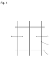
- Fig. 1
- eine schematische Darstellung einer Ganzglasfassade;
- Fig. 2
- eine Querschnittsdarstellung einer Ganzglasfassade gemäß dem Stand der Technik;
- Fig. 2a
- eine Querschnittsdarstellung einer Ganzglasfassade gemäß dem Stand der Technik;
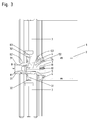
- Fig. 3
- eine Querschnittsdarstellung einer erfindungsgemäßen Ganzglasfassade;
- Fig. 4
- eine Querschnittsdarstellung einer erfindungsgemäßen Ganzglasfassade;
- Fig. 5
- eine perspektivische Darstellung einer erfindungsgemäßen Ganzglasfassade;
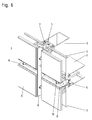
- Fig. 6
- eine perspektivische Darstellung einer erfindungsgemäßen Ganzglasfassade.
- Folgende Bezugszeichen werden in den Abbildungen verwendet:
- A
- Absperrprofil (Stand der Technik)
- 1
- Pfosten
- 2
- Riegel
- 3
- Flächenelement
- 4
- Dichtung
- 5
- Glashalter
- 6
- Spalt
- 7
- Dämmprofil
- 8
- Absperrprofil
- 9
- Silikon
- 10
- Schraube
- 11
- Gewindenut
- 31
- Seitenfläche
- 32
- Öffnung (Nut)
- 51
- Flügel
- 52
- Schaft
- 53
- Bohrung
- 71
- Bohrung
- 81
- Grundfläche
- 82
- Schenkel
- 83
- Bohrung
- Zunächst wird auf
Fig. 1 Bezug genommen. - Eine erfindungsgemäße Ganzglasfassade umfasst im Wesentlichen eine Fassaden-Trägerkonstruktion, mindestens ein, vorzugsweise mehrere, Glashalter 5 und eine Anzahl von Flächenelementen 3. Zur räumlichen Orientierung soll nachfolgend davon ausgegangen werden, dass die Fassaden-Trägerkonstruktion einer Wand, insbesondere einer Hauswand, zugewandt ist, wohingegen die Flächenelemente vor der Fassaden-Trägerkonstruktion angeordnet sind. Bei den Flächenelementen handelt es sich vorzugsweise um Verbundglasscheiben. Andere Flächenelemente, beispielsweise Kunststoffplatten, Stahlplatten, Paneele etc. sind denkbar.
- Die Fassaden-Trägerkonstruktion umfasst im Wesentlichen Pfosten 1 und Riegel 2. Bei den Pfosten 1 handelt es sich um längliche Aluminiumhohlprofile, die in einer üblichen Montageposition vertikal und über Kopf ausgerichtet sind. Bei den Riegeln 2 handelt es sich um längliche Aluminiumhohlprofile, die in einer üblichen Montageposition horizontal ausgerichtet sind. Selbstverständlich sind hier andere Materialien bzw. Profilformen denkbar. Die Pfosten 1 und Riegel 2 sind zu einer gitterartigen Fassaden-Trägerkonstruktion mit etwa quadratischen oder rechteckförmigen Öffnungen zusammengesetzt. Die Flächenelemente 3 sind im Wesentlichen vor den Öffnungen der Fassaden-Trägerkonstruktion angeordnet. Zur Abdichtung und Auflage der Flächenelemente 3 auf der Fassaden-Trägerkonstruktion sind Dichtungen 4 vorgesehen.
- Der Glashalter 5 weist zwei Flügel 51 und einen Schaft 52 auf. Der Schaft 52 ist endseitig mit der Fassaden-Trägerkonstruktion verbunden. Auf der gegenüberliegenden Seite des Schaftes 52 sind die Flügel 51 vorgesehen, die sich im Wesentlichen senkrecht von dem Schaft 52 erstrecken. Insgesamt handelt es sich bei dem Glashalter 5 vorzugsweise um ein im Querschnitt etwa T- oder L-förmiges Metallprofil mit Kunststoffkappe.
- Zur Verbindung der Flächenelemente 3 mit der Fassaden-Trägerkonstruktion sind die verwendeten Glashalter 5 einerseits mit der Fassaden-Trägerkonstruktion und andererseits mit den jeweiligen Flächenelementen 3 verbunden. Zur Verbindung des Glashalters 5 mit dem Flächenelement 3, ist in mindestens einer Seitenfläche 31 des Flächenelementes eine Öffnung 32, insbesondere eine Nut, vorgesehen. In diese Öffnung 32 kann der Flügel 51 des Glashalters 5 entsprechend eingreifen.
- In einem montierten Zustand zweier Flächenelemente 3 stehen sich zwei Seitenflächen 31 der vorgenannten Flächenelemente 3 gegenüber und bilden zwischen sich einen Spalt 6 aus. In diesen Spalt 6 ragen, neben den Glashaltern 5, auch Dämmprofile 7. Es handelt sich hierbei um Profile aus Schaum oder Kunststoff mit Hohlkammern, die ebenfalls an der Fassaden-Trägerkonstruktion angebracht sind. Die Dämmprofile 7 können zwischen den jeweils in Längsrichtung beabstandeten Glashaltern 5, je nach Anforderung an die Wärmedämmung, angebracht sein. Grundsätzlich kann aber auch auf die Dämmprofile 7 verzichtet werden, wenn beispielsweise keine besonderen Anforderungen an die Wärmedämmung gestellt werden.
- Der vorgenannte Spalt 6 ist - sofern keine Kaschiermaßnahmen vorgenommen werden - für einen Betrachter der Ganzglasfassade sichtbar. Zur Kaschierung und auch zur weiteren Abdichtung der Fassade wird dieser Spalt 6 zumindest mit Silikon 9 oder ähnlichen Füllstoffen verschlossen. Um sicher zu stellen, dass das Silikon 9 nicht in den Bereich des Glashalters 5 gelangt, ist ein Absperrprofil A, 8 vorgesehen, welches an dem mindestens einen Glashalter 5 angebracht ist und sich mindestens über die Breite des Spaltes 6 erstreckt. Vorzugsweise handelt es sich bei dem Absperrprofil A, 8 um ein längliches Absperrprofil, welches, sofern mehrere Glashalter 5 in dem Spalt 6 angebracht sind, mit jedem Glashalter 5 verbunden ist. Vorzugsweise erstreckt sich das Absperrprofil A, 8 entsprechend über die Länge des Spaltes 6. Das Absperrprofil A, 8 ist im Wesentlichen parallel zu den Pfosten 1 bzw. Riegeln 2 ausgerichtet.
- Gemäß dem Stand der Technik (
Fig. 2 und Fig. 2a ) handelt es sich bei dem Absperrprofil A im Wesentlichen um ein Flachprofil, welches den beispielsweise mit Silikon 9 zu verfüllenden Spalt 6 entsprechend abdichtet, so dass kein flüssiges Silikon 9 in den Bereich der Glashalter 5 bzw. Dämmprofile 7 gelangen kann. Eine derartige Konstruktion ist jedoch wenig einbruchssicher. Das Silikon 9 kann entfernt werden, wodurch die Glashalter 5 zugänglich werden. Mit entsprechenden Hebelwerkzeugen kann das Flächenelement 3 aus der Ganzglasfassade ausgehebelt werden. - Erfindungsgemäß ist vorgesehen, dass das Absperrprofil 8 zumindest abschnittsweise im Querschnitt U-förmig ausgebildet ist, insbesondere demnach eine Grundfläche 81 und zwei Schenkel 82 aufweist. Mit dieser Ausgestaltung des Absperrprofils 8 ist es weiterhin möglich, den Spalt 6 derart abzudichten, dass kein Silikon 9 in den Bereich der Glashalter 5 bzw. Dämmprofile 7 gelangt. Zusätzlich ermöglicht ein erfindungsgemäßes Absperrprofil 8 den Zugang zu den Glashaltern 5 bzw. Dämmprofilen 7 und auch zu den Seitenflächen 31 der Flächenelemente 3 zu versperren, auch wenn das Silikon 9 entfernt worden ist. Hierzu verhindern die Schenkel 82 des im Querschnitt U-förmigen Absperrprofils 8, dass ein Werkzeug unbefugt in der Bereich der Glashalter 5 gelangen kann.
- Es kann vorzugsweise vorgesehen sein, dass es sich bei dem Absperrprofil 8 um ein längliches, im Querschnitt U-förmiges Aluminiumprofil handelt. Denkbar sind selbstverständlich auch andere Werkstoffe, wie beispielsweise Stahl oder Kunststoff. Auch kann das Absperrprofil 8 nur abschnittsweise einen U-förmigen Querschnitt und abschnittsweise einen anderen Querschnitt, beispielsweise einen L-förmigen Querschnitt, aufweisen. Insbesondere mit der letztgenannten Ausgestaltung des Absperrprofils 8 kann eine sehr selektive Einbruchssicherung ausschließlich im Bereich der Glashalter 5 vorgenommen werden. Die Dämmprofile 7 können beispielsweise lediglich durch den L-förmigen Querschnitt überdeckt sein. Auch kann ein derartiges Absperrprofil 8 an unterschiedliche Spaltmaße angepasst sein.
- Auch kann vorgesehen sein, dass das erfindungsgemäße U-förmige Absperrprofil 8 auf besonders robuste Art und Weise mit der Fassaden-Trägerkonstruktion, insbesondere dem jeweiligen Pfosten 1 oder dem Riegel 2, und/oder dem Glashalter 5 und/oder dem Dämmprofil 7 verbunden ist. Hier sind unterschiedliche Möglichkeiten denkbar. Vorzugsweise ist mindestens eine Schraube 10 vorgesehen, die durch eine Bohrung 83 des U-förmigen Absperrprofils 8 und durch eine entsprechende Durchgangsbohrung 53 des Glashalters 5 und/oder Durchgangsbohrung 71 des Dämmprofils 7 hindurchgesteckt und in eine Bohrung oder Gewindenut 11 des Pfostens 1 oder Riegels 2 eingeschraubt wird.
- Zur Erhöhung des Einbruchsschutzes kann ferner vorgesehen sein, dass der Kopf der mindestens einen Schraube 10 nach der Montage unbrauchbar gemacht wird. Dies kann beispielsweise dadurch geschehen, dass ein Kopf mit einem Inbusloch oder Torxloch ausgewählt wird, wobei das Inbusloch bzw. Torxloch nach der Montage ausgebohrt wird.
Claims (10)
- Ganzglasfassade, umfassend mindestens- eine Fassaden-Trägerkonstruktion (1, 2) und- eine Anzahl von Flächenelementen (3), die vor der Fassaden-Trägerkonstruktion (1, 2) angebracht sind, wobei- mindestens zwei Flächenelemente (3), insbesondere zwei zueinander gewandete Seitenflächen (31) der Flächenelemente (3), einen Spalt (6) ausbilden, wobei- mindestens ein Glashalter (5) vorgesehen ist, der mit der Fassaden-Trägerkonstruktion (1, 2) und den Flächenelementen (3) verbunden ist und sich durch einen Abschnitt des Spalts (6) erstreckt, wobei- der Spalt (6) teilweise mit Silikon (9) ausgefüllt ist, wobei- zwischen dem Silikon (9) und dem mindestens einen Glashalter (5) ein Absperrprofil angebracht ist,dadurch gekennzeichnet, dass
das Absperrprofil (8) zumindest abschnittsweise einen U-förmigen Querschnitt aufweist. - Ganzglasfassade nach Anspruch 1, dadurch gekennzeichnet, dass die Fassaden-Trägerkonstruktion eine Anzahl von Pfosten (1) und Riegeln (2) aufweist, die eine gitterförmige Fassaden-Trägerkonstruktion ausbilden.
- Ganzglasfassade nach mindestens einem der vorhergehenden Ansprüche, dadurch gekennzeichnet, dass die Fassaden-Trägerkonstruktion Öffnungen ausbildet, wobei die Flächenelemente (3) jeweils vor den Öffnungen der Fassaden-Trägerkonstruktion angeordnet sind.
- Ganzglasfassade nach mindestens einem der vorhergehenden Ansprüche, dadurch gekennzeichnet, dass es sich bei den Flächenelementen (3) um Verbundglasscheiben handelt.
- Ganzglasfassade nach mindestens einem der vorhergehenden Ansprüche, dadurch gekennzeichnet, dass der mindestens eine Glashalter (5) einen Schaft (52) und zwei sich von dem Schaft erstreckende Schenkel (51) aufweist, wobei die Schenkel (51) in Öffnungen (32), insbesondere in Nuten, der Flächenelemente (3), insbesondere in den Seitenflächen (31) der Flächenelemente (3), eingreifen.
- Ganzglasfassade nach mindestens einem der vorhergehenden Ansprüche, dadurch gekennzeichnet, dass mindestens ein Dämmprofil (7) vorgesehen ist, welches in den Spalt (6) hineinragt.
- Ganzglasfassade nach mindestens einem der vorhergehenden Ansprüche, dadurch gekennzeichnet, dass es sich bei dem Absperrprofil (8) um ein längliches Profil, insbesondere Aluminiumprofil, handelt.
- Ganzglasfassade nach mindestens einem der vorhergehenden Ansprüche, dadurch gekennzeichnet, dass das Absperrprofil (8) abschnittsweise einen L-förmigen Querschnitt aufweist.
- Ganzglasfassade nach mindestens einem der vorhergehenden Ansprüche, dadurch gekennzeichnet, dass das Absperrprofil (8) mittels mindestens einer Schraube (10) mit der Fassaden-Trägerkonstruktion (1, 2) und/oder mit dem mindestens einen Glashalter (5) und/oder mit dem mindestens einen Dämmprofil (7) verbunden ist.
- Ganzglasfassade nach mindestens einem der vorhergehenden Ansprüche, dadurch gekennzeichnet, dass der Kopf der mindestens eine Schraube (10) nach der Montage unbrauchbar gemacht worden ist.
Applications Claiming Priority (1)
| Application Number | Priority Date | Filing Date | Title |
|---|---|---|---|
| DE102010011315.8A DE102010011315B4 (de) | 2010-03-13 | 2010-03-13 | Ganzglasfassade |
Publications (4)
| Publication Number | Publication Date |
|---|---|
| EP2365179A2 true EP2365179A2 (de) | 2011-09-14 |
| EP2365179A3 EP2365179A3 (de) | 2016-08-24 |
| EP2365179B1 EP2365179B1 (de) | 2025-04-16 |
| EP2365179B8 EP2365179B8 (de) | 2025-05-28 |
Family
ID=43920653
Family Applications (1)
| Application Number | Title | Priority Date | Filing Date |
|---|---|---|---|
| EP11155830.0A Active EP2365179B8 (de) | 2010-03-13 | 2011-02-24 | Ganzglasfassade |
Country Status (2)
| Country | Link |
|---|---|
| EP (1) | EP2365179B8 (de) |
| DE (1) | DE102010011315B4 (de) |
Cited By (2)
| Publication number | Priority date | Publication date | Assignee | Title |
|---|---|---|---|---|
| CN106522429A (zh) * | 2016-08-31 | 2017-03-22 | 安徽超洋装饰工程股份有限公司 | 隐框玻璃幕墙用玻璃托件结构 |
| CN112796439A (zh) * | 2021-01-12 | 2021-05-14 | 深圳市方大建科集团有限公司 | 一种玻璃幕墙系统 |
Families Citing this family (1)
| Publication number | Priority date | Publication date | Assignee | Title |
|---|---|---|---|---|
| DE102023104097A1 (de) * | 2023-02-20 | 2024-08-22 | HUECK System GmbH & Co. KG | Glasträger für pfosten-riegel-fassaden |
Citations (1)
| Publication number | Priority date | Publication date | Assignee | Title |
|---|---|---|---|---|
| DE3624491C2 (de) | 1986-07-19 | 1992-07-02 | Fa. Eduard Hueck Metallwalz- Und Presswerk, 5880 Luedenscheid, De |
Family Cites Families (8)
| Publication number | Priority date | Publication date | Assignee | Title |
|---|---|---|---|---|
| DE3439436A1 (de) * | 1984-10-27 | 1986-04-30 | SCHÜCO Heinz Schürmann GmbH & Co, 4800 Bielefeld | Aussenwand- und dachverglasung |
| IT1189582B (it) * | 1986-06-19 | 1988-02-04 | Manfredo Alessi | Vetrate strutturali con giunzioni realizzate mediante sigillanti strutturali ed elementi metallici |
| DE3735490A1 (de) * | 1987-10-20 | 1989-05-03 | Noerdlingen Glashandel | Haltemittel zur befestigung bzw. sicherung von glasscheiben, insbesondere mehrscheibigen isolierglasscheiben, an hochbaukonstruktionen |
| US4961975A (en) | 1988-11-14 | 1990-10-09 | Walter Bejnar | Sealed glass unit |
| BE1003942A4 (fr) | 1990-10-01 | 1992-07-22 | Portal S A | Vitre, procede et outil pour sa fabrication. |
| EP0957227B1 (de) | 1998-05-13 | 2002-02-27 | Harald Dr.-Ing. Schulz | Fassadenkonstruktion |
| DE19821518A1 (de) * | 1998-05-13 | 1999-11-25 | Pitscheider Ingenieurbuero Dr | Fassadenkonstruktion |
| JP2008116031A (ja) | 2006-10-31 | 2008-05-22 | Otake:Kk | 防犯ネジカバー |
-
2010
- 2010-03-13 DE DE102010011315.8A patent/DE102010011315B4/de active Active
-
2011
- 2011-02-24 EP EP11155830.0A patent/EP2365179B8/de active Active
Patent Citations (1)
| Publication number | Priority date | Publication date | Assignee | Title |
|---|---|---|---|---|
| DE3624491C2 (de) | 1986-07-19 | 1992-07-02 | Fa. Eduard Hueck Metallwalz- Und Presswerk, 5880 Luedenscheid, De |
Cited By (2)
| Publication number | Priority date | Publication date | Assignee | Title |
|---|---|---|---|---|
| CN106522429A (zh) * | 2016-08-31 | 2017-03-22 | 安徽超洋装饰工程股份有限公司 | 隐框玻璃幕墙用玻璃托件结构 |
| CN112796439A (zh) * | 2021-01-12 | 2021-05-14 | 深圳市方大建科集团有限公司 | 一种玻璃幕墙系统 |
Also Published As
| Publication number | Publication date |
|---|---|
| DE102010011315B4 (de) | 2026-07-02 |
| DE102010011315A1 (de) | 2011-09-15 |
| EP2365179B1 (de) | 2025-04-16 |
| EP2365179B8 (de) | 2025-05-28 |
| EP2365179A3 (de) | 2016-08-24 |
Similar Documents
| Publication | Publication Date | Title |
|---|---|---|
| EP4080008B1 (de) | Tür, fenster oder fassadenelement sowie beschlaganordnung für ein solches element | |
| DE102009023883B4 (de) | Fassadenelement | |
| DE19501101A1 (de) | Aus Profilstäben gebildete, miteinander verbundene Pfosten und Riegel | |
| DE2059829A1 (de) | Struktursystem fuer den Zusammenbau von vorgefertigten Konstruktionen | |
| EP2792834B1 (de) | Anordnung umfassend ein Halteprofil für ein Rahmenprofil sowie rahmenintegrierte Absturzsicherung | |
| EP2365179B1 (de) | Ganzglasfassade | |
| DE102012100016A1 (de) | Profilsystem für Fassaden, Fenster und Türen | |
| EP2450519B1 (de) | Gebäudeabschluss in einbruchhemmender Ausführung | |
| DE10049666A1 (de) | Tür, insbesondere Sicherheitstür (AKZ aus der Jahresreihe 100 wird vergeben) | |
| EP1835084B1 (de) | Isolator für eine aus Profilen bestehende Pfosten/Riegel-Fassadenkonstruktion | |
| EP1098046B1 (de) | Verkleidungssystem für Fassaden und Dächer von Bauwerken | |
| DE19633001A1 (de) | Einbruchsicheres Fenster | |
| EP0725203B1 (de) | Bewehrung an Türen, Fenstern oder Fassaden | |
| EP3211147B1 (de) | Pfosten-riegel-konstruktion | |
| EP3098361B1 (de) | Flächenkonstruktion für die ausbildung von wänden, trennwänden, fassaden und dgl | |
| EP2295698B1 (de) | Profilanordnung, insbesondere für ein Fenster oder eine Tür sowie Fenster oder Tür | |
| EP2436848B1 (de) | Tragwerkkonstruktion | |
| DE102007033984A1 (de) | Blendrahmenkonstruktion sowie Blendrahmenanordnung | |
| DE19736860C2 (de) | Wärmegedämmte Fassade mit Fensterbändern | |
| DE102018126446A1 (de) | Tragelement in Isolationsverbundsystemen | |
| EP2990561B1 (de) | Fassade | |
| DE102004016215A1 (de) | Pfosten-Riegel-System mit geringer Ansichtsbreite | |
| DE102007053659A1 (de) | Gebäudefassade in Brandschutzausführung | |
| EP3543424B1 (de) | Modulares tragprofil für plattenelemente | |
| CH676269A5 (de) |
Legal Events
| Date | Code | Title | Description |
|---|---|---|---|
| PUAI | Public reference made under article 153(3) epc to a published international application that has entered the european phase |
Free format text: ORIGINAL CODE: 0009012 |
|
| AK | Designated contracting states |
Kind code of ref document: A2 Designated state(s): AL AT BE BG CH CY CZ DE DK EE ES FI FR GB GR HR HU IE IS IT LI LT LU LV MC MK MT NL NO PL PT RO RS SE SI SK SM TR |
|
| AX | Request for extension of the european patent |
Extension state: BA ME |
|
| RAP1 | Party data changed (applicant data changed or rights of an application transferred) |
Owner name: HUECK GMBH & CO. KG |
|
| PUAL | Search report despatched |
Free format text: ORIGINAL CODE: 0009013 |
|
| AK | Designated contracting states |
Kind code of ref document: A3 Designated state(s): AL AT BE BG CH CY CZ DE DK EE ES FI FR GB GR HR HU IE IS IT LI LT LU LV MC MK MT NL NO PL PT RO RS SE SI SK SM TR |
|
| AX | Request for extension of the european patent |
Extension state: BA ME |
|
| RIC1 | Information provided on ipc code assigned before grant |
Ipc: E06B 3/54 20060101AFI20160721BHEP Ipc: E06B 5/11 20060101ALI20160721BHEP |
|
| STAA | Information on the status of an ep patent application or granted ep patent |
Free format text: STATUS: REQUEST FOR EXAMINATION WAS MADE |
|
| 17P | Request for examination filed |
Effective date: 20170224 |
|
| RBV | Designated contracting states (corrected) |
Designated state(s): AL AT BE BG CH CY CZ DE DK EE ES FI FR GB GR HR HU IE IS IT LI LT LU LV MC MK MT NL NO PL PT RO RS SE SI SK SM TR |
|
| STAA | Information on the status of an ep patent application or granted ep patent |
Free format text: STATUS: EXAMINATION IS IN PROGRESS |
|
| 17Q | First examination report despatched |
Effective date: 20200720 |
|
| GRAP | Despatch of communication of intention to grant a patent |
Free format text: ORIGINAL CODE: EPIDOSNIGR1 |
|
| STAA | Information on the status of an ep patent application or granted ep patent |
Free format text: STATUS: GRANT OF PATENT IS INTENDED |
|
| INTG | Intention to grant announced |
Effective date: 20241111 |
|
| RIN1 | Information on inventor provided before grant (corrected) |
Inventor name: VOLKELT, THOMAS |
|
| GRAS | Grant fee paid |
Free format text: ORIGINAL CODE: EPIDOSNIGR3 |
|
| GRAA | (expected) grant |
Free format text: ORIGINAL CODE: 0009210 |
|
| STAA | Information on the status of an ep patent application or granted ep patent |
Free format text: STATUS: THE PATENT HAS BEEN GRANTED |
|
| AK | Designated contracting states |
Kind code of ref document: B1 Designated state(s): AL AT BE BG CH CY CZ DE DK EE ES FI FR GB GR HR HU IE IS IT LI LT LU LV MC MK MT NL NO PL PT RO RS SE SI SK SM TR |
|
| REG | Reference to a national code |
Ref country code: GB Ref legal event code: FG4D Free format text: NOT ENGLISH |
|
| REG | Reference to a national code |
Ref country code: CH Ref legal event code: PK Free format text: BERICHTIGUNG B8 Ref country code: CH Ref legal event code: EP Ref country code: DE Ref legal event code: R096 Ref document number: 502011017494 Country of ref document: DE |
|
| RAP2 | Party data changed (patent owner data changed or rights of a patent transferred) |
Owner name: HYDRO BUILDING SYSTEMS LUEDENSCHEID GMBH |
|
| REG | Reference to a national code |
Ref country code: IE Ref legal event code: FG4D Free format text: LANGUAGE OF EP DOCUMENT: GERMAN |
|
| REG | Reference to a national code |
Ref country code: NL Ref legal event code: MP Effective date: 20250416 |
|
| PG25 | Lapsed in a contracting state [announced via postgrant information from national office to epo] |
Ref country code: NL Free format text: LAPSE BECAUSE OF FAILURE TO SUBMIT A TRANSLATION OF THE DESCRIPTION OR TO PAY THE FEE WITHIN THE PRESCRIBED TIME-LIMIT Effective date: 20250416 |
|
| PG25 | Lapsed in a contracting state [announced via postgrant information from national office to epo] |
Ref country code: FI Free format text: LAPSE BECAUSE OF FAILURE TO SUBMIT A TRANSLATION OF THE DESCRIPTION OR TO PAY THE FEE WITHIN THE PRESCRIBED TIME-LIMIT Effective date: 20250416 Ref country code: PT Free format text: LAPSE BECAUSE OF FAILURE TO SUBMIT A TRANSLATION OF THE DESCRIPTION OR TO PAY THE FEE WITHIN THE PRESCRIBED TIME-LIMIT Effective date: 20250818 Ref country code: ES Free format text: LAPSE BECAUSE OF FAILURE TO SUBMIT A TRANSLATION OF THE DESCRIPTION OR TO PAY THE FEE WITHIN THE PRESCRIBED TIME-LIMIT Effective date: 20250416 |
|
| REG | Reference to a national code |
Ref country code: LT Ref legal event code: MG9D |
|
| PG25 | Lapsed in a contracting state [announced via postgrant information from national office to epo] |
Ref country code: NO Free format text: LAPSE BECAUSE OF FAILURE TO SUBMIT A TRANSLATION OF THE DESCRIPTION OR TO PAY THE FEE WITHIN THE PRESCRIBED TIME-LIMIT Effective date: 20250716 Ref country code: GR Free format text: LAPSE BECAUSE OF FAILURE TO SUBMIT A TRANSLATION OF THE DESCRIPTION OR TO PAY THE FEE WITHIN THE PRESCRIBED TIME-LIMIT Effective date: 20250717 |
|
| PG25 | Lapsed in a contracting state [announced via postgrant information from national office to epo] |
Ref country code: PL Free format text: LAPSE BECAUSE OF FAILURE TO SUBMIT A TRANSLATION OF THE DESCRIPTION OR TO PAY THE FEE WITHIN THE PRESCRIBED TIME-LIMIT Effective date: 20250416 |
|
| PG25 | Lapsed in a contracting state [announced via postgrant information from national office to epo] |
Ref country code: BG Free format text: LAPSE BECAUSE OF FAILURE TO SUBMIT A TRANSLATION OF THE DESCRIPTION OR TO PAY THE FEE WITHIN THE PRESCRIBED TIME-LIMIT Effective date: 20250416 |
|
| PG25 | Lapsed in a contracting state [announced via postgrant information from national office to epo] |
Ref country code: HR Free format text: LAPSE BECAUSE OF FAILURE TO SUBMIT A TRANSLATION OF THE DESCRIPTION OR TO PAY THE FEE WITHIN THE PRESCRIBED TIME-LIMIT Effective date: 20250416 |
|
| PG25 | Lapsed in a contracting state [announced via postgrant information from national office to epo] |
Ref country code: RS Free format text: LAPSE BECAUSE OF FAILURE TO SUBMIT A TRANSLATION OF THE DESCRIPTION OR TO PAY THE FEE WITHIN THE PRESCRIBED TIME-LIMIT Effective date: 20250716 |
|
| PG25 | Lapsed in a contracting state [announced via postgrant information from national office to epo] |
Ref country code: IS Free format text: LAPSE BECAUSE OF FAILURE TO SUBMIT A TRANSLATION OF THE DESCRIPTION OR TO PAY THE FEE WITHIN THE PRESCRIBED TIME-LIMIT Effective date: 20250816 |
|
| PG25 | Lapsed in a contracting state [announced via postgrant information from national office to epo] |
Ref country code: LV Free format text: LAPSE BECAUSE OF FAILURE TO SUBMIT A TRANSLATION OF THE DESCRIPTION OR TO PAY THE FEE WITHIN THE PRESCRIBED TIME-LIMIT Effective date: 20250416 |
|
| PG25 | Lapsed in a contracting state [announced via postgrant information from national office to epo] |
Ref country code: SM Free format text: LAPSE BECAUSE OF FAILURE TO SUBMIT A TRANSLATION OF THE DESCRIPTION OR TO PAY THE FEE WITHIN THE PRESCRIBED TIME-LIMIT Effective date: 20250416 Ref country code: DK Free format text: LAPSE BECAUSE OF FAILURE TO SUBMIT A TRANSLATION OF THE DESCRIPTION OR TO PAY THE FEE WITHIN THE PRESCRIBED TIME-LIMIT Effective date: 20250416 |
|
| REG | Reference to a national code |
Ref country code: DE Ref legal event code: R097 Ref document number: 502011017494 Country of ref document: DE |
|
| PG25 | Lapsed in a contracting state [announced via postgrant information from national office to epo] |
Ref country code: CZ Free format text: LAPSE BECAUSE OF FAILURE TO SUBMIT A TRANSLATION OF THE DESCRIPTION OR TO PAY THE FEE WITHIN THE PRESCRIBED TIME-LIMIT Effective date: 20250416 |
|
| PG25 | Lapsed in a contracting state [announced via postgrant information from national office to epo] |
Ref country code: RO Free format text: LAPSE BECAUSE OF FAILURE TO SUBMIT A TRANSLATION OF THE DESCRIPTION OR TO PAY THE FEE WITHIN THE PRESCRIBED TIME-LIMIT Effective date: 20250416 Ref country code: SK Free format text: LAPSE BECAUSE OF FAILURE TO SUBMIT A TRANSLATION OF THE DESCRIPTION OR TO PAY THE FEE WITHIN THE PRESCRIBED TIME-LIMIT Effective date: 20250416 |
|
| PG25 | Lapsed in a contracting state [announced via postgrant information from national office to epo] |
Ref country code: IT Free format text: LAPSE BECAUSE OF FAILURE TO SUBMIT A TRANSLATION OF THE DESCRIPTION OR TO PAY THE FEE WITHIN THE PRESCRIBED TIME-LIMIT Effective date: 20250416 |
|
| PLBE | No opposition filed within time limit |
Free format text: ORIGINAL CODE: 0009261 |
|
| STAA | Information on the status of an ep patent application or granted ep patent |
Free format text: STATUS: NO OPPOSITION FILED WITHIN TIME LIMIT |
|
| REG | Reference to a national code |
Ref country code: CH Ref legal event code: L10 Free format text: ST27 STATUS EVENT CODE: U-0-0-L10-L00 (AS PROVIDED BY THE NATIONAL OFFICE) Effective date: 20260225 |
|
| REG | Reference to a national code |
Ref country code: CH Ref legal event code: U11 Free format text: ST27 STATUS EVENT CODE: U-0-0-U10-U11 (AS PROVIDED BY THE NATIONAL OFFICE) Effective date: 20260301 |
|
| 26N | No opposition filed |
Effective date: 20260119 |
|
| PGFP | Annual fee paid to national office [announced via postgrant information from national office to epo] |
Ref country code: GB Payment date: 20260219 Year of fee payment: 16 |
|
| PGFP | Annual fee paid to national office [announced via postgrant information from national office to epo] |
Ref country code: DE Payment date: 20260128 Year of fee payment: 16 |
|
| PGFP | Annual fee paid to national office [announced via postgrant information from national office to epo] |
Ref country code: AT Payment date: 20260128 Year of fee payment: 16 |
|
| PGFP | Annual fee paid to national office [announced via postgrant information from national office to epo] |
Ref country code: FR Payment date: 20260123 Year of fee payment: 16 |
|
| PGFP | Annual fee paid to national office [announced via postgrant information from national office to epo] |
Ref country code: CH Payment date: 20260301 Year of fee payment: 16 |
|
| PG25 | Lapsed in a contracting state [announced via postgrant information from national office to epo] |
Ref country code: LT Free format text: LAPSE BECAUSE OF FAILURE TO SUBMIT A TRANSLATION OF THE DESCRIPTION OR TO PAY THE FEE WITHIN THE PRESCRIBED TIME-LIMIT Effective date: 20250416 |
|
| PG25 | Lapsed in a contracting state [announced via postgrant information from national office to epo] |
Ref country code: SE Free format text: LAPSE BECAUSE OF FAILURE TO SUBMIT A TRANSLATION OF THE DESCRIPTION OR TO PAY THE FEE WITHIN THE PRESCRIBED TIME-LIMIT Effective date: 20250416 |