EP2359384B1 - Kathodenabschirmung bei deuteriumlampen - Google Patents
Kathodenabschirmung bei deuteriumlampen Download PDFInfo
- Publication number
- EP2359384B1 EP2359384B1 EP09760729.5A EP09760729A EP2359384B1 EP 2359384 B1 EP2359384 B1 EP 2359384B1 EP 09760729 A EP09760729 A EP 09760729A EP 2359384 B1 EP2359384 B1 EP 2359384B1
- Authority
- EP
- European Patent Office
- Prior art keywords
- cathode
- housing
- anode
- lamp
- window
- Prior art date
- Legal status (The legal status is an assumption and is not a legal conclusion. Google has not performed a legal analysis and makes no representation as to the accuracy of the status listed.)
- Active
Links
Images

Classifications
-
- H—ELECTRICITY
- H01—ELECTRIC ELEMENTS
- H01J—ELECTRIC DISCHARGE TUBES OR DISCHARGE LAMPS
- H01J61/00—Gas-discharge or vapour-discharge lamps
- H01J61/68—Lamps in which the main discharge is between parts of a current-carrying guide, e.g. halo lamp
-
- H—ELECTRICITY
- H01—ELECTRIC ELEMENTS
- H01J—ELECTRIC DISCHARGE TUBES OR DISCHARGE LAMPS
- H01J61/00—Gas-discharge or vapour-discharge lamps
- H01J61/02—Details
- H01J61/04—Electrodes; Screens; Shields
- H01J61/10—Shields, screens, or guides for influencing the discharge
Definitions
- the invention relates to a gas discharge lamp, in particular a deuterium lamp, with a housing base made of an insulating material.
- the cathode In the deuterium lamps most commonly used today, the cathode is surrounded by a metal housing which is at the same potential as the anode compartment and the molded body. This leads to the formation of secondary discharges, which lead to a reflection of transmitted light bulbs. Further, the side discharge causes a molding erosion takes place and reduces the intensity of the lamp, since the discharge current can not flow completely through the molding.
- the housing consists of a total of six parts, which are all subject to tolerances and must be welded together. Since the tolerances add independently, the series scattering is disproportionately large, especially in the front housing part.
- Such deuterium lamps also require a lot of time for assembly. It consists of both the front and the rear housing part made of metal, wherein the two housing parts are usually connected by a metallic intermediate wall.
- the cathode is surrounded by the housing front and the cathode window, which are mounted on the intermediate wall.
- the cathode window and the molded body are thus structurally connected to each other conductive.
- the shaped body and the cathode window are at the same potential, but which is lower than the plasma potential at the location of the shaped body.
- positive ions from the plasma are accelerated on the shaped body and contribute to its removal.
- the diameter of the diaphragm increases and the electrode density in the diaphragm decreases, as a result of which the lamp loses its UV intensity and the removed material of the shaped body is reflected on the inside of the piston and thus has a reduction in the intensity of the lamp result.
- the DE 199 01 919 A1 describes a miniature deuterium arc lamp.
- the deuterium arc lamp has a structure attached to the distal end of the electrical conductor in an elongated glass bulb at a distance from the glass bulb, wherein the spacer means, which are engaged with the structure and located at a small distance from the piston, around to limit the transverse movement of the structure in the piston, are provided.
- the anode is arranged by an intermediate dielectric, transversely spaced from a baffle.
- Spacer devices secure the anode, the baffle, and the intervening dielectric which have been cantilevered to the end of the conductor in previously known deuterium lamps.
- the EP 0 727 810 A2 describes a gas discharge tube having a focusing support member of an insulator, the focus electrode support member having a front surface and a rear surface facing the front surface, a hot cathode for emitting glow electrodes, the cathode being on the front surface side of the focus electrode support member; an anode for receiving the thermoelectrons that emits the thermionic cathode, the anode being located on the back surface side of the focussing electrode support member and facing an opening of the through hole; a focusing electrode supported by the focusing electrode support member and having a focusing opening located at a position of an opening from the converging-section through hole of the glow electrodes; a spacer between the focus electrode support member and the anode in contact with both the back surface of the focus electrode support member and a front surface of the anode; and an anode support member of an insulator, wherein the anode support member is located on an opposite side of the focus electrode support member through the anode and
- the DE 11 2005 001 775 describes a gas discharge tube in which a sealed container, an anode and a cathode are provided and a conductive member restricting a discharge path, the conductive member being disposed between the anode and the cathode and reducing the discharge path between the anode and the cathode is trained. Further, the gas discharge tube has a cathode cover which is made of ceramic and encloses the cathode. In this gas discharge tube, as in the DE 11 2005 001 775 is enclosed by the cathode-side cover portion, the cathode cover, in which only the slot for emitting electrons is provided as a required minimum opening. Thereby, the heat holding effect of the cathode is remarkably maintained by the cathode-side cover portion and the power consumption is reduced.
- the ceramic housing thus serves to maintain the heat within the cathode compartment.
- the discharge lamps described here have the consequence that secondary discharges occur and thus form body erosion takes place at the diaphragm. This leads to the fact that the intensity or the lifetime of the gas discharge lamp decreases significantly. Furthermore, the discharge lamps described above are expensive to assemble.
- the object of the invention is therefore to provide a gas discharge lamp, which has a reduced shape-body erosion and thus a reduction of the series dispersion and thus causes an increase in the intensity and the life and thus avoids the above-mentioned disadvantages.
- the gas discharge lamp according to the invention comprises a lamp bulb filled with gas, an anode arranged inside the lamp bulb, a cathode which is arranged at a distance from the anode within the bulb and a housing with a molded body, a housing rear wall and one which is at least partially non-electrically conductive
- a housing base wherein the housing base has a housing front, a housing intermediate wall and a cathode compartment, and a cathode shield, wherein the housing front and the housing intermediate wall made of ceramic and the cathode shield window comprises a metal and is insulated from the mold body and the housing back wall, wherein the housing rear wall comprises a metal ,
- the invention provides that the shaped body consists of a refractory metal, in particular of molybdenum.
- a refractory metal in particular of molybdenum.
- the discharge is constricted by the shaped body, whereby the charge carrier concentration in the interior of the shaped body is greatly increased and a punctiform light source is formed.
- the gas temperature likewise rises, which entails a strong thermal load on the shaped body.
- the housing base is a housing base comprising a ceramic and / or a quartz.
- a housing base thus consists of a non-electrically conductive material and thus electrically insulates the cathode window against the molding.
- a conductive connection between the cathode window and the molded body can not take place due to the potential difference in the plasma, to a sidestream from the cathode window via the intermediate wall to the molded body.
- Such a side stream would lead to loss of intensity in the UV range, since the current of the discharge is no longer available.
- a current would also affect the expansion of the molded body over the life of the lamp.
- a housing base as described above which comprises a ceramic and / or a quartz, such a side stream can be prevented, and the resulting effects. It is thus achieved a significant increase in intensity and an increase in the life of the deuterium lamp.
- the invention provides that the housing base comprises a housing front and a housing intermediate wall and a housing rear wall made of nickel.
- the housing base comprises a housing front and a housing intermediate wall and a housing rear wall made of nickel.
- FIG. 1 is a deuterium lamp 1 with a cathode space 28, which completely encloses the cathode 10.
- the cathode compartment 28 is part of the housing base 14, which includes, inter alia, a housing front 16 and a housing intermediate wall 22.
- a cathode 10 and an anode 12 are located within the deuterium lamp 1.
- a discharge is formed between the cathode 10 and the anode 12, which delivers a continuous UV spectrum.
- the discharge is constricted by the shaped body 18.
- the charge carrier concentration is increased significantly in the interior of the molded body 18 and a point-shaped light source is formed.
- the cathode 10 is enclosed by a cathode space 28, wherein the cathode space 28 has a circular opening in the direction of the optical axis of the deuterium lamp 1, which forms the cathode window 30.
- the optical axis is defined by the openings in the molded body 18 and in the anode 12. Through the cathode window 30, the discharge path is bent at right angles to the optical axis.
- the cathode window 30 therefore has the task of defining the discharge path and is in direct contact with the plasma within the deuterium lamp 1.
- the cathode chamber 28 is made of an electrically non-conductive material and thus isolates the cathode window 30 against the shaped body 18.
- the conductive connection between the cathode window 30 and molded body 18, which due to the potential difference in Plasma would form and would lead to an electrical side current from the cathode window 30 via the housing base 40 to the molded body 18 avoided.
- Such a sidestream leads to a loss of intensity, since the current of the discharge is no longer available and causes inter alia that this current also experiences a widening of the shaped body 18 over the life of the lamp, since it acts as a kind of auxiliary cathode and positive Sputtered particles from the plasma is sputtered.
- the ceramic cathode compartment is fastened with two rivets to the intermediate wall and to the housing front 16. Riveting provides mechanical stability while maintaining high precision. This ensures a precise distance between the cathode window 30 and the molded body 18.
- the remaining components of the deuterium lamp 1 are made of metal and are welded together to also achieve increased stability.
- a deuterium lamp 1 is shown with a housing base 14 made of ceramic.
- the deuterium lamp 1 comprises, among other things, an airtight piston 1 and a housing base 14.
- the piston 1 is filled with gas, here deuterium.
- the housing which also comprises the housing base 14, further comprises, inter alia, cathode 10, anode 12, molded body 18, a cathode shielding window 20 and a housing rear wall 24.
- the housing base 14 is made of an insulating material, in this case ceramic.
- the charge carrier concentration in the interior of the molded body 18 is greatly increased and there is a punctiform light source, as it is needed for many applications.
- An increase in the charge carrier concentration causes the gas temperature rises and the molded body 18 is highly thermally stressed. Therefore, the molded body 18 is made of a refractory metal, here molybdenum.
- housing front 16 and housing intermediate wall 22 are combined to form a component which forms the housing base 14. This causes the assembly of the housing front and the housing intermediate wall 22 is significantly reduced by reducing the components and a better reproducibility in the assembly of the parts is guaranteed, since these two parts are combined as one component.
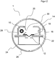
- the cathode compartment 28 is in FIG. 2 is formed by the housing base 14 and the cathode shielding window 20 enclosing the cathode 10.
- the cathode shield window 20 has a slot-shaped opening in the direction of the optical axis of the deuterium lamp 1, the so-called cathode window.
- the optical axis of the deuterium lamp is defined by the opening in the molded body 18 and in the anode 12.
- the cathode window 30 Through the cathode window 30, the discharge path is bent at right angles to the optical axis.
- the cathode window 30 has the task of determining the discharge path and is therefore in direct contact with the plasma.
- the cathode window 30 is made of metal because it must withstand the reactive plasma.
- the housing base 14 is made of an electrically nonconductive material.
- a conductive connection between the cathode window 30 and molded body 18 is avoided, which would lead to an electrical side stream from the cathode window 30 via the intermediate wall to the molded body 18 due to the potential difference in the plasma.
- a sidestream leads to a loss of intensity in the UV range, since the current of the discharge is no longer available and moreover causes a widening of the shaped body 18 over the life of the lamp takes place, since the shaped body 18 serves as a kind of auxiliary cathode and sputtered from positively charged particles from the plasma.
- the cathode shield window 20 is guided in the intermediate wall by a slot-shaped recess and fixed to the housing front 16 by two rivets stable. Overall, the molded body 18 is fixed by a total of four rivets on the housing intermediate wall 22.
- the slot-shaped recess defines exactly the position of the cathode shielding window 30 and its distance from the molded body 18.
- the riveted joint provides for low tolerances and high mechanical stability, which is particularly necessary for a stable UV intensity.
- the cathode 10 is supported directly in the bore on the opposite side of the cathode space in the housing base 14 and no longer needs to be isolated by an additional component. This prevents additional tolerances from occurring. Furthermore, the position of the cathode is thus defined and held more accurately.
- the rear wall is also fastened with four rivets on the opposite side of the housing intermediate wall 22. Due to the simplified construction of the deuterium lamp 1 in FIG. 2 Manufacturing tolerances are reduced and at the same time there is a cost savings by shortening the production time.
Landscapes
- Vessels And Coating Films For Discharge Lamps (AREA)
Applications Claiming Priority (2)
| Application Number | Priority Date | Filing Date | Title |
|---|---|---|---|
| DE102008062410A DE102008062410A1 (de) | 2008-12-17 | 2008-12-17 | Kathodenabschirmung bei Deuteriumlampen |
| PCT/EP2009/008077 WO2010069439A1 (de) | 2008-12-17 | 2009-11-13 | Kathodenabschirmung bei deuteriumlampen |
Publications (2)
| Publication Number | Publication Date |
|---|---|
| EP2359384A1 EP2359384A1 (de) | 2011-08-24 |
| EP2359384B1 true EP2359384B1 (de) | 2017-01-04 |
Family
ID=41559477
Family Applications (1)
| Application Number | Title | Priority Date | Filing Date |
|---|---|---|---|
| EP09760729.5A Active EP2359384B1 (de) | 2008-12-17 | 2009-11-13 | Kathodenabschirmung bei deuteriumlampen |
Country Status (7)
| Country | Link |
|---|---|
| US (1) | US8319432B2 (enExample) |
| EP (1) | EP2359384B1 (enExample) |
| JP (1) | JP5490135B2 (enExample) |
| CN (1) | CN102257596B (enExample) |
| AU (1) | AU2009328728B2 (enExample) |
| DE (1) | DE102008062410A1 (enExample) |
| WO (1) | WO2010069439A1 (enExample) |
Families Citing this family (5)
| Publication number | Priority date | Publication date | Assignee | Title |
|---|---|---|---|---|
| JP2010182637A (ja) * | 2009-02-09 | 2010-08-19 | Fujifilm Corp | 有機電界発光素子の製造方法及び有機電界発光素子 |
| US9360187B2 (en) * | 2010-10-04 | 2016-06-07 | Hamamatsu Photonics K. K. | Light source |
| DE102013107694A1 (de) * | 2013-07-18 | 2015-01-22 | Heraeus Noblelight Gmbh | Gasentladungslampe und deren Verwendung |
| DE102014105028A1 (de) | 2014-04-09 | 2015-04-09 | Heraeus Noblelight Gmbh | Gasentladungslampe und deren Verwendung |
| CN105470089B (zh) * | 2015-12-29 | 2024-02-09 | 深圳市槟城电子股份有限公司 | 一种气体放电管及其所用金属化电极 |
Family Cites Families (19)
| Publication number | Priority date | Publication date | Assignee | Title |
|---|---|---|---|---|
| JP3361644B2 (ja) | 1995-02-17 | 2003-01-07 | 浜松ホトニクス株式会社 | ガス放電管 |
| JP3361402B2 (ja) * | 1995-03-01 | 2003-01-07 | 浜松ホトニクス株式会社 | ガス放電管 |
| JP3361401B2 (ja) * | 1995-02-17 | 2003-01-07 | 浜松ホトニクス株式会社 | ガス放電管 |
| US5684363A (en) * | 1995-02-17 | 1997-11-04 | Hamamatsu Photonics K.K. | Deuterium gas discharge tube |
| EP1045428B1 (en) * | 1997-12-24 | 2005-02-16 | Hamamatsu Photonics K.K. | Gas discharge tube |
| US6078132A (en) | 1998-01-21 | 2000-06-20 | Imaging & Sensing Technology Corporation | Miniature deuterium arc lamp |
| JP4237411B2 (ja) * | 1998-09-07 | 2009-03-11 | 浜松ホトニクス株式会社 | ガス放電管 |
| JP2000173548A (ja) * | 1998-12-09 | 2000-06-23 | Hamamatsu Photonics Kk | ガス放電管 |
| JP4964360B2 (ja) * | 2000-11-15 | 2012-06-27 | 浜松ホトニクス株式会社 | ガス放電管 |
| JP4907760B2 (ja) * | 2000-11-15 | 2012-04-04 | 浜松ホトニクス株式会社 | ガス放電管 |
| JP2004519077A (ja) * | 2001-02-08 | 2004-06-24 | イメージング アンド センシング テクノロジー コーポレーション | ガス入りアーク放電灯およびその製造方法 |
| JP4006005B2 (ja) * | 2002-04-30 | 2007-11-14 | 浜松ホトニクス株式会社 | ガス放電管 |
| JP3984179B2 (ja) * | 2003-02-20 | 2007-10-03 | 浜松ホトニクス株式会社 | ガス放電管 |
| JP4969772B2 (ja) | 2004-08-10 | 2012-07-04 | 浜松ホトニクス株式会社 | ガス放電管 |
| JP4907852B2 (ja) * | 2004-08-24 | 2012-04-04 | 浜松ホトニクス株式会社 | ガス放電管 |
| JP4554395B2 (ja) * | 2005-02-17 | 2010-09-29 | 浜松ホトニクス株式会社 | 光源装置 |
| JP4589142B2 (ja) * | 2005-02-17 | 2010-12-01 | 浜松ホトニクス株式会社 | 光源装置 |
| JP4932185B2 (ja) | 2005-06-30 | 2012-05-16 | 浜松ホトニクス株式会社 | ガス放電管、光源装置及び液体クロマトグラフ |
| JP4813122B2 (ja) * | 2005-08-10 | 2011-11-09 | 浜松ホトニクス株式会社 | 重水素ランプ |
-
2008
- 2008-12-17 DE DE102008062410A patent/DE102008062410A1/de not_active Ceased
-
2009
- 2009-11-13 AU AU2009328728A patent/AU2009328728B2/en active Active
- 2009-11-13 US US13/139,562 patent/US8319432B2/en active Active
- 2009-11-13 CN CN200980150626.8A patent/CN102257596B/zh active Active
- 2009-11-13 WO PCT/EP2009/008077 patent/WO2010069439A1/de not_active Ceased
- 2009-11-13 JP JP2011541129A patent/JP5490135B2/ja active Active
- 2009-11-13 EP EP09760729.5A patent/EP2359384B1/de active Active
Non-Patent Citations (1)
| Title |
|---|
| None * |
Also Published As
| Publication number | Publication date |
|---|---|
| JP2012512513A (ja) | 2012-05-31 |
| US20110266950A1 (en) | 2011-11-03 |
| DE102008062410A1 (de) | 2010-07-01 |
| WO2010069439A1 (de) | 2010-06-24 |
| JP5490135B2 (ja) | 2014-05-14 |
| CN102257596B (zh) | 2014-07-09 |
| AU2009328728A1 (en) | 2011-06-30 |
| EP2359384A1 (de) | 2011-08-24 |
| AU2009328728B2 (en) | 2013-08-15 |
| US8319432B2 (en) | 2012-11-27 |
| CN102257596A (zh) | 2011-11-23 |
Similar Documents
| Publication | Publication Date | Title |
|---|---|---|
| EP0314732B1 (de) | Xenon-kurzbogen-entlandungslampe | |
| EP2359384B1 (de) | Kathodenabschirmung bei deuteriumlampen | |
| DE69116456T2 (de) | Entladungsröhre | |
| DE19628925B4 (de) | Entladungslampe mit einer Füllung, die Deuterium, Wasserstoff, Quecksilber, ein Metallhalogenid oder Edelgas aufweist | |
| EP0337192B1 (de) | Gasentladungschalter | |
| DE1514990A1 (de) | Hohllathode | |
| EP0087820A1 (de) | Überspannungsableiter mit einem gasgefüllten Gehäuse | |
| DE3008518C2 (de) | Elektrode für eine Entladungslampe | |
| DE69926445T2 (de) | Hochdruck-Entladungslampe | |
| DE10331510B4 (de) | Kurzbogen-Entladungslampe sowie Lichtquellenvorrichtung | |
| DE69608261T2 (de) | Niederdruckentladungslampe | |
| DE635165C (de) | Elektrisches Entladungsgefaess, insbesondere Gleichrichter fuer hohe Betriebsspannungen | |
| DE3037223C2 (enExample) | ||
| EP0184876A2 (de) | Hochdruck-Gasentladungslampe mit einer aus Wolframblech bestehenden Elektrode | |
| DE3005638C2 (de) | Atomspektrallampe für die Zeeman-Atomabsorptionsspektroskopie | |
| DE102020128643B3 (de) | Deuteriumlampe | |
| DE3152140A1 (en) | Lighting system | |
| CH650104A5 (de) | Mit bombardierung durch elektronen arbeitende ionenquelle. | |
| DE3038624C2 (de) | Gasentladungs-Elektronenkanone mit einer Kaltkathode | |
| DE102007010607A1 (de) | Entladungslampe | |
| DE1059114B (de) | Kathode fuer Hochleistungs-Magnetrons und Verfahren fuer ihre Herstellung | |
| DE1489604C (de) | Gasgefullte Entladungslampe | |
| DE102013107694A1 (de) | Gasentladungslampe und deren Verwendung | |
| DE1046703B (de) | Abstimmvorrichtung fuer Hohlraumresonatoren oder Hohlleiter | |
| EP0513403A1 (de) | Gasentladungsschalter |
Legal Events
| Date | Code | Title | Description |
|---|---|---|---|
| PUAI | Public reference made under article 153(3) epc to a published international application that has entered the european phase |
Free format text: ORIGINAL CODE: 0009012 |
|
| 17P | Request for examination filed |
Effective date: 20110608 |
|
| AK | Designated contracting states |
Kind code of ref document: A1 Designated state(s): AT BE BG CH CY CZ DE DK EE ES FI FR GB GR HR HU IE IS IT LI LT LU LV MC MK MT NL NO PL PT RO SE SI SK SM TR |
|
| RIN1 | Information on inventor provided before grant (corrected) |
Inventor name: MALKMUS, ROLF Inventor name: ERNESTI, KARSTEN Inventor name: JENEK, TORSTEN |
|
| RIN1 | Information on inventor provided before grant (corrected) |
Inventor name: MALKMUS, ROLF Inventor name: ERNESTI, KARSTEN Inventor name: JENEK, TORSTEN |
|
| DAX | Request for extension of the european patent (deleted) | ||
| 17Q | First examination report despatched |
Effective date: 20120925 |
|
| GRAP | Despatch of communication of intention to grant a patent |
Free format text: ORIGINAL CODE: EPIDOSNIGR1 |
|
| INTG | Intention to grant announced |
Effective date: 20160923 |
|
| STAA | Information on the status of an ep patent application or granted ep patent |
Free format text: STATUS: GRANT OF PATENT IS INTENDED |
|
| GRAS | Grant fee paid |
Free format text: ORIGINAL CODE: EPIDOSNIGR3 |
|
| GRAA | (expected) grant |
Free format text: ORIGINAL CODE: 0009210 |
|
| STAA | Information on the status of an ep patent application or granted ep patent |
Free format text: STATUS: THE PATENT HAS BEEN GRANTED |
|
| AK | Designated contracting states |
Kind code of ref document: B1 Designated state(s): AT BE BG CH CY CZ DE DK EE ES FI FR GB GR HR HU IE IS IT LI LT LU LV MC MK MT NL NO PL PT RO SE SI SK SM TR |
|
| REG | Reference to a national code |
Ref country code: GB Ref legal event code: FG4D Free format text: NOT ENGLISH |
|
| REG | Reference to a national code |
Ref country code: CH Ref legal event code: EP |
|
| REG | Reference to a national code |
Ref country code: AT Ref legal event code: REF Ref document number: 859989 Country of ref document: AT Kind code of ref document: T Effective date: 20170115 |
|
| REG | Reference to a national code |
Ref country code: IE Ref legal event code: FG4D Free format text: LANGUAGE OF EP DOCUMENT: GERMAN |
|
| REG | Reference to a national code |
Ref country code: DE Ref legal event code: R096 Ref document number: 502009013547 Country of ref document: DE |
|
| REG | Reference to a national code |
Ref country code: LT Ref legal event code: MG4D Ref country code: NL Ref legal event code: MP Effective date: 20170104 |
|
| PG25 | Lapsed in a contracting state [announced via postgrant information from national office to epo] |
Ref country code: NL Free format text: LAPSE BECAUSE OF FAILURE TO SUBMIT A TRANSLATION OF THE DESCRIPTION OR TO PAY THE FEE WITHIN THE PRESCRIBED TIME-LIMIT Effective date: 20170104 |
|
| PG25 | Lapsed in a contracting state [announced via postgrant information from national office to epo] |
Ref country code: HR Free format text: LAPSE BECAUSE OF FAILURE TO SUBMIT A TRANSLATION OF THE DESCRIPTION OR TO PAY THE FEE WITHIN THE PRESCRIBED TIME-LIMIT Effective date: 20170104 Ref country code: LT Free format text: LAPSE BECAUSE OF FAILURE TO SUBMIT A TRANSLATION OF THE DESCRIPTION OR TO PAY THE FEE WITHIN THE PRESCRIBED TIME-LIMIT Effective date: 20170104 Ref country code: NO Free format text: LAPSE BECAUSE OF FAILURE TO SUBMIT A TRANSLATION OF THE DESCRIPTION OR TO PAY THE FEE WITHIN THE PRESCRIBED TIME-LIMIT Effective date: 20170404 Ref country code: GR Free format text: LAPSE BECAUSE OF FAILURE TO SUBMIT A TRANSLATION OF THE DESCRIPTION OR TO PAY THE FEE WITHIN THE PRESCRIBED TIME-LIMIT Effective date: 20170405 Ref country code: FI Free format text: LAPSE BECAUSE OF FAILURE TO SUBMIT A TRANSLATION OF THE DESCRIPTION OR TO PAY THE FEE WITHIN THE PRESCRIBED TIME-LIMIT Effective date: 20170104 Ref country code: IS Free format text: LAPSE BECAUSE OF FAILURE TO SUBMIT A TRANSLATION OF THE DESCRIPTION OR TO PAY THE FEE WITHIN THE PRESCRIBED TIME-LIMIT Effective date: 20170504 |
|
| PG25 | Lapsed in a contracting state [announced via postgrant information from national office to epo] |
Ref country code: PL Free format text: LAPSE BECAUSE OF FAILURE TO SUBMIT A TRANSLATION OF THE DESCRIPTION OR TO PAY THE FEE WITHIN THE PRESCRIBED TIME-LIMIT Effective date: 20170104 Ref country code: ES Free format text: LAPSE BECAUSE OF FAILURE TO SUBMIT A TRANSLATION OF THE DESCRIPTION OR TO PAY THE FEE WITHIN THE PRESCRIBED TIME-LIMIT Effective date: 20170104 Ref country code: PT Free format text: LAPSE BECAUSE OF FAILURE TO SUBMIT A TRANSLATION OF THE DESCRIPTION OR TO PAY THE FEE WITHIN THE PRESCRIBED TIME-LIMIT Effective date: 20170504 Ref country code: SE Free format text: LAPSE BECAUSE OF FAILURE TO SUBMIT A TRANSLATION OF THE DESCRIPTION OR TO PAY THE FEE WITHIN THE PRESCRIBED TIME-LIMIT Effective date: 20170104 Ref country code: BG Free format text: LAPSE BECAUSE OF FAILURE TO SUBMIT A TRANSLATION OF THE DESCRIPTION OR TO PAY THE FEE WITHIN THE PRESCRIBED TIME-LIMIT Effective date: 20170404 Ref country code: LV Free format text: LAPSE BECAUSE OF FAILURE TO SUBMIT A TRANSLATION OF THE DESCRIPTION OR TO PAY THE FEE WITHIN THE PRESCRIBED TIME-LIMIT Effective date: 20170104 |
|
| REG | Reference to a national code |
Ref country code: DE Ref legal event code: R097 Ref document number: 502009013547 Country of ref document: DE |
|
| PG25 | Lapsed in a contracting state [announced via postgrant information from national office to epo] |
Ref country code: EE Free format text: LAPSE BECAUSE OF FAILURE TO SUBMIT A TRANSLATION OF THE DESCRIPTION OR TO PAY THE FEE WITHIN THE PRESCRIBED TIME-LIMIT Effective date: 20170104 Ref country code: CZ Free format text: LAPSE BECAUSE OF FAILURE TO SUBMIT A TRANSLATION OF THE DESCRIPTION OR TO PAY THE FEE WITHIN THE PRESCRIBED TIME-LIMIT Effective date: 20170104 Ref country code: SK Free format text: LAPSE BECAUSE OF FAILURE TO SUBMIT A TRANSLATION OF THE DESCRIPTION OR TO PAY THE FEE WITHIN THE PRESCRIBED TIME-LIMIT Effective date: 20170104 Ref country code: RO Free format text: LAPSE BECAUSE OF FAILURE TO SUBMIT A TRANSLATION OF THE DESCRIPTION OR TO PAY THE FEE WITHIN THE PRESCRIBED TIME-LIMIT Effective date: 20170104 |
|
| PLBE | No opposition filed within time limit |
Free format text: ORIGINAL CODE: 0009261 |
|
| STAA | Information on the status of an ep patent application or granted ep patent |
Free format text: STATUS: NO OPPOSITION FILED WITHIN TIME LIMIT |
|
| REG | Reference to a national code |
Ref country code: FR Ref legal event code: PLFP Year of fee payment: 9 |
|
| PG25 | Lapsed in a contracting state [announced via postgrant information from national office to epo] |
Ref country code: SM Free format text: LAPSE BECAUSE OF FAILURE TO SUBMIT A TRANSLATION OF THE DESCRIPTION OR TO PAY THE FEE WITHIN THE PRESCRIBED TIME-LIMIT Effective date: 20170104 Ref country code: DK Free format text: LAPSE BECAUSE OF FAILURE TO SUBMIT A TRANSLATION OF THE DESCRIPTION OR TO PAY THE FEE WITHIN THE PRESCRIBED TIME-LIMIT Effective date: 20170104 |
|
| 26N | No opposition filed |
Effective date: 20171005 |
|
| PG25 | Lapsed in a contracting state [announced via postgrant information from national office to epo] |
Ref country code: SI Free format text: LAPSE BECAUSE OF FAILURE TO SUBMIT A TRANSLATION OF THE DESCRIPTION OR TO PAY THE FEE WITHIN THE PRESCRIBED TIME-LIMIT Effective date: 20170104 |
|
| PG25 | Lapsed in a contracting state [announced via postgrant information from national office to epo] |
Ref country code: MC Free format text: LAPSE BECAUSE OF FAILURE TO SUBMIT A TRANSLATION OF THE DESCRIPTION OR TO PAY THE FEE WITHIN THE PRESCRIBED TIME-LIMIT Effective date: 20170104 |
|
| PG25 | Lapsed in a contracting state [announced via postgrant information from national office to epo] |
Ref country code: LU Free format text: LAPSE BECAUSE OF NON-PAYMENT OF DUE FEES Effective date: 20171113 |
|
| REG | Reference to a national code |
Ref country code: BE Ref legal event code: MM Effective date: 20171130 |
|
| REG | Reference to a national code |
Ref country code: IE Ref legal event code: MM4A |
|
| PG25 | Lapsed in a contracting state [announced via postgrant information from national office to epo] |
Ref country code: MT Free format text: LAPSE BECAUSE OF FAILURE TO SUBMIT A TRANSLATION OF THE DESCRIPTION OR TO PAY THE FEE WITHIN THE PRESCRIBED TIME-LIMIT Effective date: 20170104 |
|
| PG25 | Lapsed in a contracting state [announced via postgrant information from national office to epo] |
Ref country code: IE Free format text: LAPSE BECAUSE OF NON-PAYMENT OF DUE FEES Effective date: 20171113 |
|
| PG25 | Lapsed in a contracting state [announced via postgrant information from national office to epo] |
Ref country code: BE Free format text: LAPSE BECAUSE OF NON-PAYMENT OF DUE FEES Effective date: 20171130 |
|
| REG | Reference to a national code |
Ref country code: AT Ref legal event code: MM01 Ref document number: 859989 Country of ref document: AT Kind code of ref document: T Effective date: 20171113 |
|
| PG25 | Lapsed in a contracting state [announced via postgrant information from national office to epo] |
Ref country code: AT Free format text: LAPSE BECAUSE OF NON-PAYMENT OF DUE FEES Effective date: 20171113 |
|
| REG | Reference to a national code |
Ref country code: DE Ref legal event code: R082 Ref document number: 502009013547 Country of ref document: DE Representative=s name: BRAND, NORMEN, DR. RER. NAT., DE Ref country code: DE Ref legal event code: R082 Ref document number: 502009013547 Country of ref document: DE Representative=s name: EULER, MATTHIAS, DR., DE Ref country code: DE Ref legal event code: R082 Ref document number: 502009013547 Country of ref document: DE Representative=s name: BRAND, NORMEN, DIPL.-CHEM. UNIV. DR. RER. NAT., DE |
|
| PG25 | Lapsed in a contracting state [announced via postgrant information from national office to epo] |
Ref country code: HU Free format text: LAPSE BECAUSE OF FAILURE TO SUBMIT A TRANSLATION OF THE DESCRIPTION OR TO PAY THE FEE WITHIN THE PRESCRIBED TIME-LIMIT; INVALID AB INITIO Effective date: 20091113 |
|
| PG25 | Lapsed in a contracting state [announced via postgrant information from national office to epo] |
Ref country code: CY Free format text: LAPSE BECAUSE OF NON-PAYMENT OF DUE FEES Effective date: 20170104 |
|
| REG | Reference to a national code |
Ref country code: DE Ref legal event code: R082 Ref document number: 502009013547 Country of ref document: DE Representative=s name: BRAND, NORMEN, DR. RER. NAT., DE Ref country code: DE Ref legal event code: R082 Ref document number: 502009013547 Country of ref document: DE Representative=s name: BRAND, NORMEN, DIPL.-CHEM. UNIV. DR. RER. NAT., DE |
|
| PG25 | Lapsed in a contracting state [announced via postgrant information from national office to epo] |
Ref country code: MK Free format text: LAPSE BECAUSE OF FAILURE TO SUBMIT A TRANSLATION OF THE DESCRIPTION OR TO PAY THE FEE WITHIN THE PRESCRIBED TIME-LIMIT Effective date: 20170104 |
|
| PG25 | Lapsed in a contracting state [announced via postgrant information from national office to epo] |
Ref country code: TR Free format text: LAPSE BECAUSE OF FAILURE TO SUBMIT A TRANSLATION OF THE DESCRIPTION OR TO PAY THE FEE WITHIN THE PRESCRIBED TIME-LIMIT Effective date: 20170104 |
|
| P01 | Opt-out of the competence of the unified patent court (upc) registered |
Effective date: 20230530 |
|
| REG | Reference to a national code |
Ref country code: DE Ref legal event code: R082 Ref document number: 502009013547 Country of ref document: DE Representative=s name: MEWBURN ELLIS LLP, DE |
|
| PGFP | Annual fee paid to national office [announced via postgrant information from national office to epo] |
Ref country code: DE Payment date: 20241127 Year of fee payment: 16 |
|
| PGFP | Annual fee paid to national office [announced via postgrant information from national office to epo] |
Ref country code: GB Payment date: 20241127 Year of fee payment: 16 |
|
| PGFP | Annual fee paid to national office [announced via postgrant information from national office to epo] |
Ref country code: FR Payment date: 20241126 Year of fee payment: 16 |
|
| PGFP | Annual fee paid to national office [announced via postgrant information from national office to epo] |
Ref country code: IT Payment date: 20241122 Year of fee payment: 16 |
|
| PGFP | Annual fee paid to national office [announced via postgrant information from national office to epo] |
Ref country code: CH Payment date: 20241201 Year of fee payment: 16 |
|
| REG | Reference to a national code |
Ref country code: CH Ref legal event code: U11 Free format text: ST27 STATUS EVENT CODE: U-0-0-U10-U11 (AS PROVIDED BY THE NATIONAL OFFICE) Effective date: 20251201 |