EP2357375A2 - Fliehkraftbetätigte Koppeleinrichtung - Google Patents
Fliehkraftbetätigte Koppeleinrichtung Download PDFInfo
- Publication number
- EP2357375A2 EP2357375A2 EP11000848A EP11000848A EP2357375A2 EP 2357375 A2 EP2357375 A2 EP 2357375A2 EP 11000848 A EP11000848 A EP 11000848A EP 11000848 A EP11000848 A EP 11000848A EP 2357375 A2 EP2357375 A2 EP 2357375A2
- Authority
- EP
- European Patent Office
- Prior art keywords
- coupling device
- spring
- centrifugal
- flyweight
- securing element
- Prior art date
- Legal status (The legal status is an assumption and is not a legal conclusion. Google has not performed a legal analysis and makes no representation as to the accuracy of the status listed.)
- Granted
Links
Images



Classifications
-
- F—MECHANICAL ENGINEERING; LIGHTING; HEATING; WEAPONS; BLASTING
- F16—ENGINEERING ELEMENTS AND UNITS; GENERAL MEASURES FOR PRODUCING AND MAINTAINING EFFECTIVE FUNCTIONING OF MACHINES OR INSTALLATIONS; THERMAL INSULATION IN GENERAL
- F16D—COUPLINGS FOR TRANSMITTING ROTATION; CLUTCHES; BRAKES
- F16D43/00—Automatic clutches
- F16D43/02—Automatic clutches actuated entirely mechanically
- F16D43/04—Automatic clutches actuated entirely mechanically controlled by angular speed
- F16D43/14—Automatic clutches actuated entirely mechanically controlled by angular speed with centrifugal masses actuating the clutching members directly in a direction which has at least a radial component; with centrifugal masses themselves being the clutching members
- F16D43/18—Automatic clutches actuated entirely mechanically controlled by angular speed with centrifugal masses actuating the clutching members directly in a direction which has at least a radial component; with centrifugal masses themselves being the clutching members with friction clutching members
Definitions
- the invention relates to a centrifugal force-actuated coupling device of the type specified in the preamble of claim 1.
- the centrifugal clutch When using the centrifugal clutch in hand-held implements such as chainsaws, brushcutters or the like.
- the weight of the centrifugal clutch should be as small as possible and on the other hand, the size in the axial direction as small as possible.
- the invention has for its object to provide a centrifugal force-coupled coupling device of the generic type, which has a simple structure and low weight.
- the securing element is formed integrally with the centrifugal weight, it may be made small. Compared to coupling devices with separate disc for axial securing, the width is reduced, and the weight of the lock washer can be saved.
- the structure of the coupling device is simplified because no additional components are required for the fuse element. A wrong assembly of the fuse element, which is possible with a separate design of the fuse element is excluded. Assembly is simplified as fewer components need to be mounted.
- the securing element secures at least one spring in the direction of the axis of rotation.
- the securing element serves in particular to hold the spring in case of damage or breakage on the centrifugal clutch and to prevent lateral deflection or falling out.
- the spring is advantageously arranged over part of its length in a recording on the flyweight.
- the receptacle has on its radially inner side and on its radially outer side a securing element for the spring.
- the distance between the securing elements is advantageously smaller than the outer diameter of the spring. This can be prevented in a simple manner that the spring can be deflected laterally when spring break.
- the securing elements are advantageously arranged on the opposite side of the centrifugal weight of a clutch drum, since a deflection of the spring to the side facing the clutch drum is avoided by the clutch drum itself.
- the securing element is designed as a wedge-shaped retaining lug arranged adjacent to the circumference of the spring.
- the retaining lug can be made very small. It only narrows the receptacle so that the spring or fragments of the spring can not fall out. The size in the axial direction is not increased by the securing element, so that compared to known arrangements space can be saved.
- At least two centrifugal weights are provided, wherein the spring is designed as a helical tension spring and is hooked with its ends to adjacent centrifugal weights. Between the centrifugal weights advantageously a space bridged by the spring is formed. At least one radial securing element is advantageously provided, which is formed integrally with a centrifugal weight, and which protrudes on the radially outer side of the spring adjacent to the spring in the intermediate space. As a result, falling out of a broken spring section radially outwards can be prevented in a simple manner.
- the distance between the fuse elements is particularly dimensioned so that it is about 0.5 times to about twice the wire diameter of the spring in the idle state of the coupling device. As a result, it is possible to prevent neighboring flyweights from touching even under unfavorable manufacturing tolerances. At the same time it can be prevented that fragments of the spring escape radially outward. Since the fuse elements can be made comparatively small, there is only a slight increase in the total weight. Compared with known safety arrangements, the total weight of the clutch assembly is reduced.
- the outer diameter of the spring corresponds at least to the thickness of the centrifugal weight.
- the flyweights are therefore designed so narrow that they do not protrude laterally beyond the spring.
- the width of the coupling device is determined by the diameter of the required spring.
- a securing element secures the position of the centrifugal weight on the holder in the direction of the axis of rotation.
- centrifugal clutches separate holders are provided for this purpose.
- the holders are additional components that complicate the structure of the coupling device and increase the weight.
- a simple design results when the securing element is formed on the centrifugal weight as a guide web, which projects into a guide groove formed in the holder. This allows the flyweight be axially secured against the holder in both directions.
- the guide groove is formed on the guide neck of the holder and the guide web is formed integrally with the flyweight and protrudes into the guide slot of the flyweight.
- the flyweight made of metal is advantageous.
- at least one securing element is sintered to the centrifugal weight.
- the securing element can be produced with the flyweight in a common manufacturing process. Separate manufacturing steps for the production of the fuse element are not needed.
- An advantageous construction results when three centrifugal weights are provided, which are interconnected via three springs.
- the coupling device is in particular a centrifugal clutch, which has a clutch drum against which the flyweights in the radially outer position.
- the coupling device may also be a centrifugal force-operated braking device or the like ..
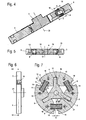
- Fig. 1 shows as an exemplary embodiment of a centrifugal force-actuated coupling device, a centrifugal clutch 1.
- the centrifugal clutch 1 can also be a centrifugal force Braking device or the like. Be provided.
- the centrifugal clutch 1 is advantageously arranged in the drive train in a hand-held implement such as a power saw, a power cutter, a brushcutter or the like. Between the drive motor and the tool to be driven and connects the tool rotatably connected to the drive shaft of the engine when a structurally predetermined engagement speed is exceeded. When idling the drive motor, which is designed in particular as an internal combustion engine, the engine is usually separated from the tool.
- the centrifugal clutch 1 has a holder 3, which, as in Fig. 2 is shown schematically, rotatably connected to a drive shaft 8 is connected.
- the holder 3 has three radially outwardly projecting guide stub 4, on each of which a flyweight 5 is arranged.
- the three identically designed centrifugal weights 5 each have two suspension openings 10 for springs 6. Each spring is suspended by its ends in circumferentially adjacent flyweights 5.
- the centrifugal clutch 1 has a clutch drum 2 whose edge 23 engages over the flyweights 5 at its radially outer region. In the in the Figures 1 and 2 shown rest position pull the springs 6, the flyweights 5 in its radially inner position. If the drive shaft 8 is driven to rotate about an axis of rotation 21, which simultaneously represents the axis of symmetry of the centrifugal clutch 1, the centrifugal force acts on the flyweights 5 radially outward against the force of the springs 6. The centrifugal weights 5 become radial when a rotational speed is exceeded deflected outwards and come with their friction surface 18 in contact with the edge 23. As a result, the drive shaft 8 is frictionally connected to the clutch drum 2. On the clutch drum 2, an output shaft 9 is fixed in rotation, which in Fig. 2 is shown schematically.
- retaining lugs 12 and 13 are integrally formed on the flyweights 5 adjacent to the spring.
- the retaining lugs 12 are provided radially inwardly and the retaining lugs 13 are provided radially outwardly relative to the axis of rotation 21.
- radial retaining lugs 14 are integrally formed on the centrifugal weights 5. The design of the retaining lugs 12, 13 and 14 will be explained in more detail below.
- the centrifugal clutch 1 is comparatively narrow.
- the thickness g of the centrifugal weights 5, which is measured parallel to the axis of rotation 21, is slightly smaller than the outer diameter d of the spring 6 in the exemplary embodiment. Arranging the spring 6 in a receptacle which closes the side of the centrifugal clutch 1 facing away from the clutch drum 2 is formed, is therefore not possible with the same width of the centrifugal clutch 1.
- FIGS. 3 to 7 show the design of the centrifugal clutch 1 in detail.
- the retaining lugs 12 and 13 are formed approximately wedge-shaped.
- the retaining lugs 12 and 13 have a distance b from each other ( Fig. 7 ), which is smaller than the outer diameter d of the spring 6.
- the radial retaining lugs 14 are formed as arranged in the central region of the flyweights 5 webs extending over less than half of the thickness g of the flyweights 5. This is sufficient for retaining the springs 6.
- the flyweights 5 each have two receptacles 11 in which an end portion of the springs 6 can be arranged.
- the receptacles 11 are aligned approximately tangentially to the rotation axis 21, so that the springs 6 are arranged tangentially to a circumferential direction to the rotation axis 21.
- the receptacles 11 adjacent flyweights 5 are facing each other, so that each spring 6 can be arranged with a first end to a flyweight 5 and with a second end to an adjacent flyweight 5.
- Between adjacent flyweights 5 each have a gap 22 is formed, which has a width h. In this space 22 protrude the radial retaining lugs 14. The gap 22 is bridged by the springs 6.
- the retaining lugs 14 have a distance b to each other in the rest state, which in the embodiment slightly larger than the wire diameter c as a helical tension spring trained spring 6 is.
- the distance b is advantageously about half to about twice the wire diameter c.
- the centrifugal clutch 1 also has a safety device which secures the position of the flyweights 5 on the holder 4 in the direction of the axis of rotation 21.
- FIGS. 1 and 5 show the guide stub 4 of the holder 3 in guide slots 15 of the flyweights S.
- the guide slots 1 are aligned radially to the axis of rotation 21.
- the guide slots 15 may be formed inclined or curved to the radial direction of the rotation axis 21.
- In the guide slots 15 projects a guide web 16 which extends in the longitudinal direction of the guide slots 15 and which projects centrally into the guide slot 15.
- the guide bar 16 is formed significantly narrower than the flyweight 5.
- the guide bar 16 is encompassed by the guide stub 4 of the holder 3 on both sides.
- the guide neck 4 has a guide groove 17 into which the guide web 16 protrudes.
- FIGS. 8 to 14 show the design of the centrifugal weight 5 in detail.
- the receptacle 11 has for the spring 6 side walls 20 which extend approximately parallel to the axis of rotation 21.
- the wedge-shaped retaining lugs 12 and 13 extend from the side walls 20 into the receptacle 11.
- the depressions 19 extend, so that a smaller thickness of the centrifugal weight 5 and thus a lower total weight of the centrifugal clutch 1 results in these areas.
- a guide bar 16 is provided, the arrangement of two guide webs on the opposite sides of the guide slot 15 is possible.
- the guide bar 16 has a width e.
- the width e corresponds approximately to the in Fig. 19
- the widths e and f are advantageously about a quarter to about two-thirds of the thickness g of the flyweights 5. This results in a good guide in the axial direction.
- the guide grooves 17 are respectively provided on the same side of the guide stub 4 of the holder 3, so that there is a rotationally symmetrical shape of the holder 3.
- the holder 3 has a receptacle 7 for the drive shaft. 8
- the flyweights 5 are advantageous as well as the holder 3 and the clutch drum 2 made of metal.
- the flyweights 5 are advantageously produced in a sintering process, wherein the retaining lugs 12, 13 and 14 are sintered to the centrifugal weights 5. Additional components for axially securing the flyweights 5 or the springs 6 can be omitted by the retaining lugs 12, 13 and 14.
Landscapes
- Engineering & Computer Science (AREA)
- General Engineering & Computer Science (AREA)
- Mechanical Engineering (AREA)
- One-Way And Automatic Clutches, And Combinations Of Different Clutches (AREA)
Abstract
Description
- Die Erfindung betrifft eine fliehkraftbetätigte Koppeleinrichtung der im Oberbegriff des Anspruchs 1 angegebenen Gattung.
- Aus der
DE 94 11 945 U1 ist eine fliehkraftbetätigte Koppeleinrichtung, nämlich eine Fliehkraftkupplung bekannt, bei der ein Halter zur Sicherung der axialen Lage der Fliehgewichte vorgesehen ist. Der Halter überdeckt auch die Federn teilweise in axialer Richtung. - Bei einem Federbruch muss vermieden werden, dass die Feder aus dem Bereich der Fliehkraftkupplung ausschwenkt und mit benachbarten Teilen in Kontakt kommt und diese beschädigt oder zerstört. Hierzu ist es bekannt, die gesamte Kupplung an der der Kupplungstrommel gegenüberliegenden Seite von einer Scheibe abzudecken.
- Beim Einsatz der Fliehkraftkupplung in handgeführten Arbeitsgeräten wie Motorsägen, Freischneidern oder dgl. soll zum einen das Gewicht der Fliehkraftkupplung möglichst klein und zum anderen die Baugröße in axialer Richtung möglichst gering sein.
- Der Erfindung liegt die Aufgabe zugrunde, eine fliehkraftbetätigte Koppeleinrichtung der gattungsgemäßen Art zu schaffen, die einen einfachen Aufbau und ein geringes Gewicht besitzt.
- Diese Aufgabe wird durch eine fliehkraftbetätigte Koppeleinrichtung mit den Merkmalen des Anspruchs 1 gelöst.
- Dadurch, dass das Sicherungselement einteilig mit dem Fliehgewicht ausgebildet ist, kann es klein ausgebildet sein. Gegenüber Koppeleinrichtungen mit separater Scheibe zur axialen Sicherung verringert sich die Baubreite, und das Gewicht der Sicherungsscheibe kann eingespart werden. Der Aufbau der Koppeleinrichtung ist vereinfacht, da für das Sicherungselement keine zusätzlichen Bauteile benötigt werden. Eine Falschmontage des Sicherungselements, die bei separater Ausbildung des Sicherungselements möglich ist, ist ausgeschlossen. Die Montage ist vereinfacht, da weniger Bauteile montiert werden müssen.
- Vorteilhaft sichert das Sicherungselement mindestens eine Feder in Richtung der Drehachse. Das Sicherungselement dient dabei insbesondere dazu, die Feder bei Beschädigung oder Bruch an der Fliehkraftkupplung zu halten und ein seitliches Auslenken oder Herausfallen zu verhindern. Die Feder ist vorteilhaft über einen Teil ihrer Länge in einer Aufnahme am Fliehgewicht angeordnet. Vorteilhaft besitzt die Aufnahme an ihrer radial innenliegenden Seite und an ihrer radial außenliegenden Seite ein Sicherungselement für die Feder. Der Abstand zwischen den Sicherungselementen ist dabei vorteilhaft kleiner als der Außendurchmesser der Feder. Dadurch kann auf einfache Weise verhindert werden, dass die Feder bei Federbruch seitlich ausgelenkt werden kann. Die Sicherungselemente sind dabei vorteilhaft an der einer Kupplungstrommel gegenüberliegenden Seite des Fliehgewichts angeordnet, da ein Auslenken der Feder zu der der Kupplungstrommel zugewandten Seite durch die Kupplungstrommel selbst vermieden ist.
- Eine einfache Gestaltung ergibt sich, wenn das Sicherungselement als benachbart zum Umfang der Feder angeordnete, keilförmig ausgebildete Haltenase ausgebildet ist. Die Haltenase kann sehr klein ausgebildet sein. Sie verengt lediglich die Aufnahme so, dass die Feder oder Bruchstücke der Feder nicht herausfallen können. Die Baugröße in axialer Richtung wird durch das Sicherungselement nicht vergrößert, so dass gegenüber bekannten Anordnungen Bauraum eingespart werden kann.
- Vorteilhaft sind mindestens zwei Fliehgewichte vorgesehen, wobei die Feder als Schraubenzugfeder ausgebildet und mit ihren Enden an benachbarten Fliehgewichten eingehängt ist. Zwischen den Fliehgewichten ist dabei vorteilhaft ein von der Feder überbrückter Zwischenraum gebildet. Vorteilhaft ist mindestens ein radiales Sicherungselement vorgesehen, das einteilig mit einem Fliehgewicht ausgebildet ist, und das an der radial außenliegenden Seite der Feder benachbart zur Feder in den Zwischenraum ragt. Dadurch kann auch ein Herausfallen eines abgebrochenen Federabschnitts radial nach außen auf einfache Weise verhindert werden. Vorteilhaft ragen zwei radiale Sicherungselemente von benachbarten Fliehgewichten aufeinander zu. Der Abstand zwischen den Sicherungselementen ist dabei insbesondere so bemessen, dass er im Ruhezustand der Koppeleinrichtung etwa das 0,5fache bis etwa das 2fache des Drahtdurchmessers der Feder beträgt. Dadurch kann verhindert werden, dass sich benachbarte Fliehgewichte auch bei ungünstigen Fertigungstoleranzen berühren. Gleichzeitig kann verhindert werden, dass Bruchstücke der Feder radial nach außen entweichen. Da die Sicherungselemente vergleichsweise klein ausgebildet sein können, ergibt sich nur eine geringfügige Erhöhung des Gesamtgewichts. Verglichen mit bekannten Sicherungsanordnungen ist das Gesamtgewicht der Kupplungsanordnung verringert.
- Um insgesamt geringe Abmessungen der Kupplungseinrichtung zu erreichen, ist vorgesehen, dass der Außendurchmesser der Feder mindestens der Dicke des Fliehgewichts entspricht. Die Fliehgewichte sind demnach so schmal ausgebildet, dass sie seitlich nicht über die Feder hinausstehen. Die Breite der Kupplungseinrichtung wird vom Durchmesser der benötigten Feder bestimmt.
- Vorteilhaft sichert ein Sicherungselement die Lage des Fliehgewichts an dem Halter in Richtung der Drehachse. Bei bekannten Fliehkraftkupplungen sind hierzu separate Halter vorgesehen. Die Halter stellen zusätzliche Bauteile dar, die den Aufbau der Kupplungseinrichtung verkomplizieren und das Gewicht erhöhen. Eine einfache Gestaltung ergibt sich, wenn das Sicherungselement an dem Fliehgewicht als Führungssteg ausgebildet ist, der in eine in dem Halter ausgebildete Führungsnut ragt. Dadurch kann das Fliehgewicht gegenüber dem Halter in beide Richtungen axial gesichert werden. Insbesondere ist die Führungsnut an dem Führungsstutzen des Halters ausgebildet und der Führungssteg ist einteilig mit dem Fliehgewicht ausgebildet und ragt in den Führungsschlitz des Fliehgewichts.
- Vorteilhaft ist das Fliehgewicht aus Metall. Insbesondere ist mindestens ein Sicherungselement an dem Fliehgewicht angesintert. Dadurch kann das Sicherungselement mit dem Fliehgewicht in einem gemeinsamen Herstellungsverfahren hergestellt werden. Separate Herstellschritte für die Herstellung des Sicherungselements werden nicht benötigt. Ein vorteilhafter Aufbau ergibt sich, wenn drei Fliehgewichte vorgesehen sind, die über drei Federn miteinander verbunden sind.
- Die Koppeleinrichtung ist insbesondere eine Fliehkraftkupplung, die eine Kupplungstrommel besitzt, an der die Fliehgewichte in der radial außenliegenden Stellung anliegen. Die Koppeleinrichtung kann jedoch auch eine fliehkraftbetätigte Bremseinrichtung oder dgl. sein.
- Ein Ausführungsbeispiel der Erfindung wird im Folgenden anhand der Zeichnung erläutert. Es zeigen:
- Fig. 1
- eine Seitenansicht einer Fliehkraftkupplung,
- Fig. 2
- einen Schnitt entlang der Linie II-II in
Fig. 1 , - Fig. 3
- eine perspektivische Darstellung der Fliehkraftkupplung ohne Kupplungstrommel,
- Fig. 4
- einen Schnitt entlang der Linie IV-IV in
Fig. 1 ohne die Kupplungstrommel, - Fig. 5
- einen Schnitt entlang der Linie V-V in
Fig. 1 ohne die Kupplungstrommel, - Fig. 6
- eine Seitenansicht der Fliehkraftkupplung ohne Kupplungstrommel in Richtung des Pfeils VI in
Fig. 1 , - Fig. 7
- einen Schnitt entlang der Linie VII-VII in
Fig. 6 , - Fig. 8
- eine perspektivische Darstellung eines Fliehgewichts,
- Fig. 9
- eine Seitenansicht des Fliehgewichts aus
Fig. 8 , - Fig. 10
- einen Schnitt entlang der Linie X-X in
Fig. 9 , - Fig. 11 1
- einen Schnitt entlang der Linie XI-XI in
Fig. 9 , - Fig. 12
- eine Seitenansicht in Richtung des Pfeils XII in
Fig. 10 , - Fig. 13 3
- einen Schnitt entlang der Linie XIII-XIII in
Fig. 12 , - Fig. 14
- einen Schnitt entlang der Linie XIV-XIV in
Fig. 12 , - Fig. 15 5
- eine perspektivische Darstellung eines Halters der Fliehkraftkupplung,
- Fig. 16
- eine Seitenansicht des Halters,
- Fig. 17
- einen Schnitt entlang der Linie XVII-XVII in
Fig. 16 , - Fig. 18
- einen Schnitt entlang der Linie XVIII-XVIII in
Fig. 17 , - Fig. 19
- einen Schnitt entlang der Linie XIX-XIX in
Fig. 18 . -
Fig. 1 zeigt als Ausführungsbeispiel für eine fliehkraftbetätigte Koppeleinrichtung eine Fliehkraftkupplung 1. Anstatt der Fliehkraftkupplung 1 kann auch eine fliehkraftbetätigte Bremseinrichtung oder dgl. vorgesehen sein. Die Fliehkraftkupplung 1 ist vorteilhaft im Antriebsstrang in einem handgeführten Arbeitsgerät wie einer Motorsäge, einem Trennschleifer, einem Freischneider oder dgl. zwischen dem Antriebsmotor und dem anzutreibenden Werkzeug angeordnet und verbindet das Werkzeug drehfest mit der Antriebswelle des Motors, wenn eine konstruktiv vorgegebene Einkuppeldrehzahl überschritten ist. Im Leerlauf des Antriebsmotors, der insbesondere als Verbrennungsmotor ausgebildet ist, ist der Motor üblicherweise vom Werkzeug getrennt. Die Fliehkraftkupplung 1 besitzt einen Halter 3, der, wie inFig. 2 schematisch gezeigt ist, drehfest mit einer Antriebswelle 8 verbunden ist. Der Halter 3 besitzt drei radial nach außen ragende Führungsstutzen 4, an denen jeweils ein Fliehgewicht 5 angeordnet ist. Die drei identisch zueinander ausgebildeten Fliehgewichte 5 besitzen jeweils zwei Einhängeöffnungen 10 für Federn 6. Jede Feder ist mit ihren Enden in in Umfangsrichtung benachbarte Fliehgewichte 5 eingehängt. - Die Fliehkraftkupplung 1 besitzt eine Kupplungstrommel 2, deren Rand 23 die Fliehgewichte 5 an ihrem radial außenliegenden Bereich übergreift. In der in den
Figuren 1 und 2 gezeigten Ruhestellung ziehen die Federn 6 die Fliehgewichte 5 in ihre radial innenliegende Stellung. Wird die Antriebswelle 8 rotierend um eine Drehachse 21, die gleichzeitig die Symmetrieachse der Fliehkraftkupplung 1 darstellt, angetrieben, so wirkt die Fliehkraft auf die Fliehgewichte 5 radial nach außen entgegen der Kraft der Federn 6. Die Fliehgewichte 5 werden bei Überschreiten einer konstruktiv vorgegebenen Drehzahl radial nach außen ausgelenkt und kommen mit ihrer Reibfläche 18 in Kontakt mit dem Rand 23. Dadurch wird die Antriebswelle 8 reibschlüssig mit der Kupplungstrommel 2 verbunden. An der Kupplungstrommel 2 ist drehfest eine Abtriebswelle 9 festgelegt, die inFig. 2 schematisch gezeigt ist. - Bricht im Betrieb eine der Federn 6, so muss verhindert werden, dass sich die Feder 6 bei der Darstellung in
Fig. 2 nach links über die Fliehkraftkupplung 1 herausstellt und so benachbarte Bauteile beschädigt oder zerstört. Um die Feder 6 auch bei einem Federbruch sicher an der Fliehkraftkupplung 1 zu halten, sind an den Fliehgewichten 5 benachbart zur Feder 6 Haltenasen 12 und 13 angeformt. Dabei sind die Haltenasen 12 radial innenliegend und die Haltenasen 13 radial außenliegend bezogen auf die Drehachse 21 vorgesehen. Um zu verhindern, dass die Feder 6 in radialer Richtung heraustreten kann, sind radiale Haltenasen 14 an den Fliehgewichten 5 angeformt. Die Gestaltung der Haltenasen 12, 13 und 14 wird im Folgenden noch näher erläutert. - Wie
Fig. 2 zeigt, ist die Fliehkraftkupplung 1 vergleichweise schmal ausgebildet. Die Dicke g der Fliehgewichte 5, die parallel zur Drehachse 21 gemessen ist, ist im Ausführungsbeispiel etwas kleiner als der Außendurchmesser d der Feder 6. Ein Anordnen der Feder 6 in einer Aufnahme, die zu der der Kupplungstrommel 2 abgewandt liegenden Seite der Fliehkraftkupplung 1 geschlossen ausgebildet ist, ist deshalb bei gleicher Baubreite der Fliehkraftkupplung 1 nicht möglich. - Die
Figuren 3 bis 7 zeigen die Gestaltung der Fliehkraftkupplung 1 im Einzelnen. WieFig. 4 zeigt, sind die Haltenasen 12 und 13 etwa keilförmig ausgebildet. Die Haltenasen 12 und 13 besitzen zueinander einen Abstand b (Fig. 7 ), der kleiner als der Außendurchmesser d der Feder 6 ist. WieFig. 6 zeigt, sind die radialen Haltenasen 14 als im mittleren Bereich der Fliehgewichte 5 angeordnete Stege ausgebildet, die sich über weniger als die Hälfte der Dicke g der Fliehgewichte 5 erstrecken. Dies ist zum Zurückhalten der Federn 6 ausreichend. - Wie
Fig. 7 zeigt, besitzen die Fliehgewichte 5 jeweils zwei Aufnahmen 11, in denen ein Endabschnitt der Federn 6 angeordnet werden kann. Die Aufnahmen 11 sind dabei etwa tangential zur Drehachse 21 ausgerichtet, so dass auch die Federn 6 tangential zu einer Umfangsrichtung zur Drehachse 21 angeordnet sind. Die Aufnahmen 11 benachbarter Fliehgewichte 5 liegen einander zugewandt, so dass jede Feder 6 mit einem ersten Ende an einem Fliehgewicht 5 und mit einem zweiten Ende an einem benachbarten Fliehgewicht 5 angeordnet werden kann. Zwischen benachbarten Fliehgewichten 5 ist jeweils ein Zwischenraum 22 gebildet, der eine Breite h besitzt. In diesen Zwischenraum 22 ragen die radialen Haltenasen 14. Der Zwischenraum 22 ist von den Federn 6 überbrückt. WieFig. 7 zeigt, besitzen die Haltenasen 14 im Ruhezustand einen Abstand b zueinander, der im Ausführungsbeispiel geringfügig größer als der Drahtdurchmesser c der als Schraubenzugfeder ausgebildeten Feder 6 ist. Der Abstand b beträgt vorteilhaft etwa die Hälfte bis etwa das Doppelte des Drahtdurchmessers c. - Die Fliehkraftkupplung 1 besitzt außerdem eine Sicherungseinrichtung, die die Lage der Fliehgewichte 5 an dem Halter 4 in Richtung der Drehachse 21 sichert. Wie die
Figuren 1 und5 zeigen, ragen die Führungsstutzen 4 des Halters 3 in Führungsschlitze 15 der Fliehgewichte S. Die Führungsschlitze 1 sind radial zur Drehachse 21 ausgerichtet. Die Führungsschlitze 15 können zur radialen Richtung der Drehachse 21 jedoch auch geneigt oder gebogen ausgebildet sein. In die Führungsschlitze 15 ragt ein Führungssteg 16, der sich in Längsrichtung der Führungsschlitze 15 erstreckt und der mittig in den Führungsschlitz 15 ragt. Der Führungssteg 16 ist deutlich schmaler ausgebildet als das Fliehgewicht 5. Der Führungssteg 16 wird vom Führungsstutzen 4 des Halters 3 beidseitig umgriffen. Zur Aufnahme des Führungsstegs 16 besitzt der Führungsstutzen 4 eine Führungsnut 17, in die der Führungssteg 16 ragt. Dadurch ist die Lage der Fliehgewichte 5 gegenüber dem Halter 4 in Richtung der Drehachse 21 gesichert. - Die
Figuren 8 bis 14 zeigen die Gestaltung des Fliehgewichts 5 im Einzelnen. WieFig. 10 zeigt, besitzt die Aufnahme 11 für die Feder 6 Seitenwände 20, die etwa parallel zur Drehachse 21 verlaufen. Die keilförmigen Haltenasen 12 und 13 erstrecken sich von den Seitenwänden 20 in die Aufnahme 11. Wie die Figuren zeigen, besitzt das Fliehgewicht 5 an beiden Seiten Vertiefungen 19, die sich jeweils über etwa ein Drittel der Dicke des Fliehgewichts 5 erstrecken. Nur im Bereich des Führungsschlitzes 15 erstreckt sich das Fliehgewicht 5 über die gesamte Breite. Im Bereich der Aufnahmen 11 und der Einhängeöffnungen 10 erstrecken sich die Vertiefungen 19, so dass sich in diesen Bereichen eine geringere Dicke des Fliehgewichts 5 und damit ein geringeres Gesamtgewicht der Fliehkraftkupplung 1 ergibt. WieFig. 12 zeigt, erstreckt sich der Führungssteg 16 über annähernd die gesamte Tiefe des Führungsschlitzes 15. Im Ausführungsbeispiel ist nur auf einer Seite des Führungsschlitzes 15 ein Führungssteg 16 vorgesehen, auch die Anordnung von zwei Führungsstegen auf den gegenüberliegenden Seiten des Führungsschlitzes 15 ist jedoch möglich. - Wie
Fig. 14 zeigt, besitzt der Führungssteg 16 eine Breite e. Die Breite e entspricht etwa der inFig. 19 gezeigte Breite f der Führungsnut 17. Die Breiten e und f betragen vorteilhaft etwa ein Viertel bis etwa zwei Drittel der Dicke g der Fliehgewichte 5. Dadurch ergibt sich eine gute Führung in axialer Richtung. Wie dieFiguren 15 bis 19 zeigen, die den Halter 3 im Einzelnen zeigen, sind die Führungsnuten 17 jeweils an der gleichen Seite der Führungsstutzen 4 des Halters 3 vorgesehen, so dass sich eine rotationssymmetrische Gestalt des Halters 3 ergibt. WieFig. 16 außerdem zeigt, besitzt der Halter 3 eine Aufnahme 7 für die Antriebswelle 8. - Die Fliehgewichte 5 sind vorteilhaft ebenso wie der Halter 3 und die Kupplungstrommel 2 aus Metall. Die Fliehgewichte 5 sind vorteilhaft in einem Sinterverfahren hergestellt, wobei die Haltenasen 12, 13 und 14 an den Fliehgewichten 5 angesintert sind. Zusätzliche Bauteile zur axialen Sicherung der Fliehgewichte 5 oder der Federn 6 können durch die Haltenasen 12, 13 und 14 entfallen.
Claims (14)
- Fliehkraftbetätigte Koppeleinrichtung mit mindestens einem an einem Halter (3) radial beweglich gelagerten Fliehgewicht (5), wobei das Fliehgewicht (5) zwischen einer radial innenliegenden und einer radial außenliegenden Stellung beweglich ist, mit mindestens einer Feder (6), die das Fliehgewicht (5) in Richtung auf die radial innenliegende Stellung belastet, wobei die Koppeleinrichtung um eine Drehachse (21) drehbar angeordnet ist und wobei die Koppeleinrichtung mindestens ein Sicherungselement umfasst, das mindestens ein Bauteil der Koppeleinrichtung in Richtung der Drehachse (21) sichert,
dadurch gekennzeichnet, dass mindestens ein Sicherungselement einteilig mit dem Fliehgewicht ausgebildet ist. - Koppeleinrichtung nach Anspruch 1,
dadurch gekennzeichnet, dass das Sicherungselement mindestens eine Feder (6) in Richtung der Drehachse (21) sichert. - Koppeleinrichtung nach Anspruch 2,
dadurch gekennzeichnet, dass die Feder (6) über mindestens einen Teil ihrer Länge in einer Aufnahme (11) am Fliehgewicht (5) angeordnet ist. - Koppeleinrichtung nach Anspruch 3,
dadurch gekennzeichnet, dass die Aufnahme (11) an ihrer radial innenliegenden Seite und an ihrer radial außenliegenden Seite ein Sicherungselement für die Feder (6) besitzt, wobei der Abstand (a) zwischen den Sicherungselementen insbesondere kleiner als der Außendurchmesser (d) der Feder (6) ist. - Koppeleinrichtung nach einem der Ansprüche 2 bis 4,
dadurch gekennzeichnet, dass das Sicherungselement als benachbart zum Umfang der Feder (6) angeordnete, etwa keilförmig ausgebildete Haltenase (12, 13) ausgebildet ist. - Koppeleinrichtung nach einem der Ansprüche 1 bis 5,
dadurch gekennzeichnet, dass mindestens zwei Fliehgewichte (5) vorgesehen sind, wobei die Feder (6) als Schraubenzugfeder ausgebildet und mit ihren Enden an benachbarten Fliehgewichten (5) eingehängt ist. - Koppeleinrichtung nach Anspruch 6,
dadurch gekennzeichnet, dass zwischen den Fliehgewichten (5) ein von der Feder (6) überbrückter Zwischenraum (22) gebildet ist, wobei insbesondere mindestens ein radiales Sicherungselement vorgesehen ist, das insbesondere einteilig mit einem Fliehgewicht (5) ausgebildet ist, und das insbesondere an der radial außenliegenden Seite der Feder (6) benachbart zur Feder (6) in den Zwischenraum (22) ragt. - Koppeleinrichtung nach Anspruch 7,
dadurch gekennzeichnet, dass zwei radiale Sicherungselemente von benachbarten Fliehgewichten (5) aufeinander zu ragen, wobei der Abstand (b) zwischen den Sicherungselementen im Ruhezustand der Koppeleinrichtung etwa das 0,5fache bis etwa das 2fache des Drahtdurchmessers (c) der Feder (6) beträgt. - Koppeleinrichtung nach einem der Ansprüche 1 bis 8,
dadurch gekennzeichnet, dass der Außendurchmesser (d) der Feder (6) mindestens der Dicke (g) des Fliehgewichts (5) entspricht. - Koppeleinrichtung nach einem der Ansprüche 1 bis 9,
dadurch gekennzeichnet, dass mindestens ein Sicherungselement die Lage des Fliehgewichts (5) an dem Halter (3) in Richtung der Drehachse (21) sichert, wobei das Sicherungselement insbesondere an dem Fliehgewicht (5) als Führungssteg (16) ausgebildet ist, der in eine in dem Halter (3) ausgebildete Führungsnut ragt. - Koppeleinrichtung nach Anspruch 10,
dadurch gekennzeichnet, dass das Fliehgewicht (5) einen etwa radial ausgerichteten Führungsschlitz (15) besitzt, in den ein Führungsstutzen (4) des Halters (3) ragt, dass die Führungsnut (17) insbesondere an dem Führungsstutzen (4) des Halters (3) ausgebildet ist, und dass der Führungssteg (16) insbesondere einteilig mit dem Fliehgewicht (5) ausgebildet ist und in den Führungsschlitz (15) des Fliehgewichts (5) ragt. - Koppeleinrichtung nach einem der Ansprüche 1 bis 11,
dadurch gekennzeichnet, dass das Fliehgewicht (5) aus Metall ist. - Koppeleinrichtung nach einem der Ansprüche 1 bis 12,
dadurch gekennzeichnet, dass mindestens ein Sicherungselement an dem Fliehgewicht (5) angesintert ist. - Koppeleinrichtung nach einem der Ansprüche 1 bis 13,
dadurch gekennzeichnet, dass drei Fliehgewichte (5) vorgesehen sind, die über drei Federn (6) miteinander verbunden sind, und dass die Koppeleinrichtung insbesondere eine Fliehkraftkupplung (1) ist, die eine Kupplungstrommel (2) besitzt, an der die Fliehgewichte (5) in der radial außenliegenden Stellung anliegen.
Applications Claiming Priority (1)
| Application Number | Priority Date | Filing Date | Title |
|---|---|---|---|
| DE102010008244A DE102010008244A1 (de) | 2010-02-17 | 2010-02-17 | Fliehkraftbetätigte Koppeleinrichtung |
Publications (3)
| Publication Number | Publication Date |
|---|---|
| EP2357375A2 true EP2357375A2 (de) | 2011-08-17 |
| EP2357375A3 EP2357375A3 (de) | 2013-10-30 |
| EP2357375B1 EP2357375B1 (de) | 2015-07-29 |
Family
ID=44010110
Family Applications (1)
| Application Number | Title | Priority Date | Filing Date |
|---|---|---|---|
| EP11000848.9A Active EP2357375B1 (de) | 2010-02-17 | 2011-02-03 | Fliehkraftbetätigte Koppeleinrichtung |
Country Status (5)
| Country | Link |
|---|---|
| US (1) | US8851262B2 (de) |
| EP (1) | EP2357375B1 (de) |
| JP (1) | JP5695929B2 (de) |
| CN (1) | CN102192254B (de) |
| DE (1) | DE102010008244A1 (de) |
Families Citing this family (10)
| Publication number | Priority date | Publication date | Assignee | Title |
|---|---|---|---|---|
| CN103615482B (zh) * | 2013-12-03 | 2016-01-20 | 北京航空航天大学 | 一种微小型机械式离心摩擦限速器 |
| WO2015160972A1 (en) | 2014-04-15 | 2015-10-22 | Qmax, Llc | Helical balloon catheter |
| CN104279251A (zh) * | 2014-09-25 | 2015-01-14 | 芜湖市中亚汽车制动元件有限公司 | 离合器 |
| CN105370761A (zh) * | 2015-12-08 | 2016-03-02 | 国网山东省电力公司莱芜供电公司 | 一种电力无人直升机离合器 |
| DE102017218970B4 (de) * | 2017-10-24 | 2020-02-20 | Ford Global Technologies, Llc | Selbstsperrende Fliehkraftpendelvorrichtung und Verwendung einer derartigen Fliehkraftpendelvorrichtung |
| IT201900024217A1 (it) * | 2019-12-17 | 2021-06-17 | Engines Eng S R L | Frizione centrifuga. |
| CN112727947A (zh) * | 2020-12-31 | 2021-04-30 | 江苏杰特动力科技有限公司 | 一种发电机组自离合辅助启动装置 |
| US12146534B2 (en) | 2021-04-27 | 2024-11-19 | Hamilton Sundstrand Corporation | Flyweight damper |
| EP4098905B1 (de) * | 2021-04-27 | 2025-10-22 | Hamilton Sundstrand Corporation | Fliehgewichtsdämpfer |
| KR102826816B1 (ko) * | 2023-06-12 | 2025-06-27 | 강경순 | 원심 클러치 장치 |
Citations (1)
| Publication number | Priority date | Publication date | Assignee | Title |
|---|---|---|---|---|
| DE9411945U1 (de) | 1994-07-25 | 1995-11-30 | Dolmar GmbH, 22045 Hamburg | Fliehkraftkupplung |
Family Cites Families (20)
| Publication number | Priority date | Publication date | Assignee | Title |
|---|---|---|---|---|
| US2115819A (en) * | 1933-05-22 | 1938-05-03 | Spicer Mfg Corp | Vibration dampener |
| US2097627A (en) * | 1933-07-26 | 1937-11-02 | Spicer Mfg Corp | Vibration dampener |
| US2514228A (en) * | 1947-01-18 | 1950-07-04 | Adiel Y Dodge | Coupling |
| US2814373A (en) * | 1952-08-21 | 1957-11-26 | Rockwell Spring & Axle Co | Synchronizer |
| US2868343A (en) * | 1956-02-08 | 1959-01-13 | Automatic Steel Products Inc | Centrifugal clutch construction |
| DE2353479A1 (de) * | 1973-10-25 | 1975-04-30 | Stihl Maschf Andreas | Motorsaege, insbesondere motorkettensaege |
| DE3125444C2 (de) * | 1981-06-27 | 1984-09-06 | Heinrich Desch Kg, 5760 Arnsberg | Fliehkraftbetätigte Reibungskupplung |
| JPH01119932A (ja) | 1987-11-02 | 1989-05-12 | Matsushita Electric Ind Co Ltd | 光集積回路 |
| JPH056422Y2 (de) * | 1988-02-09 | 1993-02-18 | ||
| US4892175A (en) * | 1988-11-02 | 1990-01-09 | Illinois Tool Works Inc. | Wrap spring clutch/brake apparatus with helper clutch mechanism |
| DE8903848U1 (de) * | 1989-03-29 | 1989-06-15 | Sachs-Dolmar GmbH, 2000 Hamburg | Fliehkraftkupplung |
| US5387052A (en) * | 1993-03-09 | 1995-02-07 | M-B-W Inc. | Drive mechanism for a vibratory compactor |
| US5560465A (en) * | 1995-02-06 | 1996-10-01 | Zindler; Hugh A. | Centrifugal clutch |
| US5680920A (en) * | 1995-03-17 | 1997-10-28 | Aktiebolatet Electrolux | Centrifugal clutch |
| JPH08254246A (ja) * | 1995-03-17 | 1996-10-01 | Exedy Corp | コイルスプリング及びダンパー装置 |
| DE10118225B4 (de) * | 2001-04-12 | 2014-04-30 | Andreas Stihl Ag & Co | Fliehkraftkupplung |
| US6857515B2 (en) * | 2003-04-22 | 2005-02-22 | The Hilliard Corporation | Centrifugal clutch |
| US7021446B2 (en) * | 2003-12-03 | 2006-04-04 | Electrolux Home Products, Inc. | Centrifugal clutch with shoe retaining feature |
| JP2007024255A (ja) * | 2005-07-20 | 2007-02-01 | Exedy Corp | 遠心式クラッチ装置 |
| US7377343B2 (en) * | 2006-05-01 | 2008-05-27 | American Axle & Manufacturing, Inc. | Centrifugal clutch |
-
2010
- 2010-02-17 DE DE102010008244A patent/DE102010008244A1/de not_active Withdrawn
-
2011
- 2011-02-03 EP EP11000848.9A patent/EP2357375B1/de active Active
- 2011-02-07 US US13/021,792 patent/US8851262B2/en active Active
- 2011-02-14 JP JP2011028440A patent/JP5695929B2/ja not_active Expired - Fee Related
- 2011-02-17 CN CN201110044789.7A patent/CN102192254B/zh active Active
Patent Citations (1)
| Publication number | Priority date | Publication date | Assignee | Title |
|---|---|---|---|---|
| DE9411945U1 (de) | 1994-07-25 | 1995-11-30 | Dolmar GmbH, 22045 Hamburg | Fliehkraftkupplung |
Also Published As
| Publication number | Publication date |
|---|---|
| JP2011169464A (ja) | 2011-09-01 |
| EP2357375B1 (de) | 2015-07-29 |
| CN102192254A (zh) | 2011-09-21 |
| US20110198182A1 (en) | 2011-08-18 |
| JP5695929B2 (ja) | 2015-04-08 |
| CN102192254B (zh) | 2016-01-06 |
| DE102010008244A1 (de) | 2011-08-18 |
| EP2357375A3 (de) | 2013-10-30 |
| US8851262B2 (en) | 2014-10-07 |
Similar Documents
| Publication | Publication Date | Title |
|---|---|---|
| EP2357375B1 (de) | Fliehkraftbetätigte Koppeleinrichtung | |
| DE102008011147B4 (de) | Spielfreies Planetengetriebe mit geteilten Planetenrädern, die durch parallel zur Planetenrotationsachse angeordnete Vorspannelemente vorgespannt sind | |
| DE102008007291B4 (de) | Starteinrichtung für einen Verbrennungsmotor | |
| DE112007002295B4 (de) | Dämpfungsmechanismus | |
| DE3021189A1 (de) | Drehschwingungsdaempfer | |
| DE19522971A1 (de) | Heckenschere | |
| DE8137424U1 (de) | Dämpfungsscheibe | |
| DE3611694A1 (de) | Fliehkraftkupplung | |
| DE19510833A1 (de) | Kupplungsscheibe mit in Reihe geschalteten Federelementen | |
| DE3224863C2 (de) | ||
| DE2353479A1 (de) | Motorsaege, insbesondere motorkettensaege | |
| DE102007008327B4 (de) | Starteinrichtung für einen Verbrennungsmotor | |
| EP2944442B1 (de) | Handgeführtes arbeitsgerät mit einer kupplung und verfahren zur herstellung einer nut in der umfangswand einer kupplungstrommel eines handgeführten arbeitsgeräts | |
| DE3332766C2 (de) | Fliehkraftkupplung | |
| DE60213240T2 (de) | Anlasser für kraftfahrzeug mit verbessertem ritzel | |
| DE2756975A1 (de) | Antriebsscheibenanordnung fuer eine reibungskupplung | |
| DE4101705C2 (de) | Handgeführte Elektrowerkzeugmaschine mit einer Einrichtung zum schnellen Stillsetzen des Werkzeuges | |
| WO2017220070A1 (de) | Fliehkraftkupplung mit reibungsminimiertem koppelbolzen und antriebsstrang | |
| DE3317532A1 (de) | Torsionsdaempfungsvorrichtung, insbesondere reibungskupplung fuer kraftfahrzeuge | |
| DE10118225B4 (de) | Fliehkraftkupplung | |
| DE3616163C2 (de) | Torsionsschwingungsdämpfer | |
| DE102016213544A1 (de) | Kupplungseinrichtung | |
| DE102007031338A1 (de) | Fliehkraftkupplung | |
| EP0482285B1 (de) | Arretierungsvorrichtung | |
| EP0012250A1 (de) | Antriebsvorrichtung zum Verstellen von Fensterscheiben, Schiebedächern und dergleichen von Kraftfahrzeugen |
Legal Events
| Date | Code | Title | Description |
|---|---|---|---|
| PUAI | Public reference made under article 153(3) epc to a published international application that has entered the european phase |
Free format text: ORIGINAL CODE: 0009012 |
|
| AK | Designated contracting states |
Kind code of ref document: A2 Designated state(s): AL AT BE BG CH CY CZ DE DK EE ES FI FR GB GR HR HU IE IS IT LI LT LU LV MC MK MT NL NO PL PT RO RS SE SI SK SM TR |
|
| AX | Request for extension of the european patent |
Extension state: BA ME |
|
| PUAL | Search report despatched |
Free format text: ORIGINAL CODE: 0009013 |
|
| AK | Designated contracting states |
Kind code of ref document: A3 Designated state(s): AL AT BE BG CH CY CZ DE DK EE ES FI FR GB GR HR HU IE IS IT LI LT LU LV MC MK MT NL NO PL PT RO RS SE SI SK SM TR |
|
| AX | Request for extension of the european patent |
Extension state: BA ME |
|
| RIC1 | Information provided on ipc code assigned before grant |
Ipc: F16D 43/18 20060101AFI20130925BHEP |
|
| 17P | Request for examination filed |
Effective date: 20140426 |
|
| RBV | Designated contracting states (corrected) |
Designated state(s): AL AT BE BG CH CY CZ DE DK EE ES FI FR GB GR HR HU IE IS IT LI LT LU LV MC MK MT NL NO PL PT RO RS SE SI SK SM TR |
|
| GRAP | Despatch of communication of intention to grant a patent |
Free format text: ORIGINAL CODE: EPIDOSNIGR1 |
|
| INTG | Intention to grant announced |
Effective date: 20141105 |
|
| GRAP | Despatch of communication of intention to grant a patent |
Free format text: ORIGINAL CODE: EPIDOSNIGR1 |
|
| INTG | Intention to grant announced |
Effective date: 20150224 |
|
| GRAS | Grant fee paid |
Free format text: ORIGINAL CODE: EPIDOSNIGR3 |
|
| GRAA | (expected) grant |
Free format text: ORIGINAL CODE: 0009210 |
|
| AK | Designated contracting states |
Kind code of ref document: B1 Designated state(s): AL AT BE BG CH CY CZ DE DK EE ES FI FR GB GR HR HU IE IS IT LI LT LU LV MC MK MT NL NO PL PT RO RS SE SI SK SM TR |
|
| REG | Reference to a national code |
Ref country code: GB Ref legal event code: FG4D Free format text: NOT ENGLISH |
|
| REG | Reference to a national code |
Ref country code: CH Ref legal event code: EP |
|
| REG | Reference to a national code |
Ref country code: AT Ref legal event code: REF Ref document number: 739570 Country of ref document: AT Kind code of ref document: T Effective date: 20150815 |
|
| REG | Reference to a national code |
Ref country code: IE Ref legal event code: FG4D Free format text: LANGUAGE OF EP DOCUMENT: GERMAN |
|
| REG | Reference to a national code |
Ref country code: DE Ref legal event code: R096 Ref document number: 502011007409 Country of ref document: DE |
|
| REG | Reference to a national code |
Ref country code: LT Ref legal event code: MG4D |
|
| REG | Reference to a national code |
Ref country code: NL Ref legal event code: MP Effective date: 20150729 |
|
| PG25 | Lapsed in a contracting state [announced via postgrant information from national office to epo] |
Ref country code: LT Free format text: LAPSE BECAUSE OF FAILURE TO SUBMIT A TRANSLATION OF THE DESCRIPTION OR TO PAY THE FEE WITHIN THE PRESCRIBED TIME-LIMIT Effective date: 20150729 Ref country code: NO Free format text: LAPSE BECAUSE OF FAILURE TO SUBMIT A TRANSLATION OF THE DESCRIPTION OR TO PAY THE FEE WITHIN THE PRESCRIBED TIME-LIMIT Effective date: 20151029 Ref country code: GR Free format text: LAPSE BECAUSE OF FAILURE TO SUBMIT A TRANSLATION OF THE DESCRIPTION OR TO PAY THE FEE WITHIN THE PRESCRIBED TIME-LIMIT Effective date: 20151030 Ref country code: FI Free format text: LAPSE BECAUSE OF FAILURE TO SUBMIT A TRANSLATION OF THE DESCRIPTION OR TO PAY THE FEE WITHIN THE PRESCRIBED TIME-LIMIT Effective date: 20150729 Ref country code: LV Free format text: LAPSE BECAUSE OF FAILURE TO SUBMIT A TRANSLATION OF THE DESCRIPTION OR TO PAY THE FEE WITHIN THE PRESCRIBED TIME-LIMIT Effective date: 20150729 |
|
| PG25 | Lapsed in a contracting state [announced via postgrant information from national office to epo] |
Ref country code: SE Free format text: LAPSE BECAUSE OF FAILURE TO SUBMIT A TRANSLATION OF THE DESCRIPTION OR TO PAY THE FEE WITHIN THE PRESCRIBED TIME-LIMIT Effective date: 20150729 Ref country code: PT Free format text: LAPSE BECAUSE OF FAILURE TO SUBMIT A TRANSLATION OF THE DESCRIPTION OR TO PAY THE FEE WITHIN THE PRESCRIBED TIME-LIMIT Effective date: 20151130 Ref country code: PL Free format text: LAPSE BECAUSE OF FAILURE TO SUBMIT A TRANSLATION OF THE DESCRIPTION OR TO PAY THE FEE WITHIN THE PRESCRIBED TIME-LIMIT Effective date: 20150729 Ref country code: IS Free format text: LAPSE BECAUSE OF FAILURE TO SUBMIT A TRANSLATION OF THE DESCRIPTION OR TO PAY THE FEE WITHIN THE PRESCRIBED TIME-LIMIT Effective date: 20151129 Ref country code: HR Free format text: LAPSE BECAUSE OF FAILURE TO SUBMIT A TRANSLATION OF THE DESCRIPTION OR TO PAY THE FEE WITHIN THE PRESCRIBED TIME-LIMIT Effective date: 20150729 Ref country code: ES Free format text: LAPSE BECAUSE OF FAILURE TO SUBMIT A TRANSLATION OF THE DESCRIPTION OR TO PAY THE FEE WITHIN THE PRESCRIBED TIME-LIMIT Effective date: 20150729 Ref country code: RS Free format text: LAPSE BECAUSE OF FAILURE TO SUBMIT A TRANSLATION OF THE DESCRIPTION OR TO PAY THE FEE WITHIN THE PRESCRIBED TIME-LIMIT Effective date: 20150729 |
|
| REG | Reference to a national code |
Ref country code: FR Ref legal event code: PLFP Year of fee payment: 6 |
|
| PG25 | Lapsed in a contracting state [announced via postgrant information from national office to epo] |
Ref country code: NL Free format text: LAPSE BECAUSE OF FAILURE TO SUBMIT A TRANSLATION OF THE DESCRIPTION OR TO PAY THE FEE WITHIN THE PRESCRIBED TIME-LIMIT Effective date: 20150729 |
|
| PG25 | Lapsed in a contracting state [announced via postgrant information from national office to epo] |
Ref country code: CZ Free format text: LAPSE BECAUSE OF FAILURE TO SUBMIT A TRANSLATION OF THE DESCRIPTION OR TO PAY THE FEE WITHIN THE PRESCRIBED TIME-LIMIT Effective date: 20150729 Ref country code: EE Free format text: LAPSE BECAUSE OF FAILURE TO SUBMIT A TRANSLATION OF THE DESCRIPTION OR TO PAY THE FEE WITHIN THE PRESCRIBED TIME-LIMIT Effective date: 20150729 Ref country code: SK Free format text: LAPSE BECAUSE OF FAILURE TO SUBMIT A TRANSLATION OF THE DESCRIPTION OR TO PAY THE FEE WITHIN THE PRESCRIBED TIME-LIMIT Effective date: 20150729 Ref country code: IT Free format text: LAPSE BECAUSE OF FAILURE TO SUBMIT A TRANSLATION OF THE DESCRIPTION OR TO PAY THE FEE WITHIN THE PRESCRIBED TIME-LIMIT Effective date: 20150729 Ref country code: DK Free format text: LAPSE BECAUSE OF FAILURE TO SUBMIT A TRANSLATION OF THE DESCRIPTION OR TO PAY THE FEE WITHIN THE PRESCRIBED TIME-LIMIT Effective date: 20150729 |
|
| REG | Reference to a national code |
Ref country code: DE Ref legal event code: R097 Ref document number: 502011007409 Country of ref document: DE |
|
| PG25 | Lapsed in a contracting state [announced via postgrant information from national office to epo] |
Ref country code: RO Free format text: LAPSE BECAUSE OF FAILURE TO SUBMIT A TRANSLATION OF THE DESCRIPTION OR TO PAY THE FEE WITHIN THE PRESCRIBED TIME-LIMIT Effective date: 20150729 Ref country code: BE Free format text: LAPSE BECAUSE OF NON-PAYMENT OF DUE FEES Effective date: 20160229 |
|
| PLBE | No opposition filed within time limit |
Free format text: ORIGINAL CODE: 0009261 |
|
| STAA | Information on the status of an ep patent application or granted ep patent |
Free format text: STATUS: NO OPPOSITION FILED WITHIN TIME LIMIT |
|
| 26N | No opposition filed |
Effective date: 20160502 |
|
| PG25 | Lapsed in a contracting state [announced via postgrant information from national office to epo] |
Ref country code: SI Free format text: LAPSE BECAUSE OF FAILURE TO SUBMIT A TRANSLATION OF THE DESCRIPTION OR TO PAY THE FEE WITHIN THE PRESCRIBED TIME-LIMIT Effective date: 20150729 |
|
| PG25 | Lapsed in a contracting state [announced via postgrant information from national office to epo] |
Ref country code: MC Free format text: LAPSE BECAUSE OF FAILURE TO SUBMIT A TRANSLATION OF THE DESCRIPTION OR TO PAY THE FEE WITHIN THE PRESCRIBED TIME-LIMIT Effective date: 20150729 Ref country code: LU Free format text: LAPSE BECAUSE OF FAILURE TO SUBMIT A TRANSLATION OF THE DESCRIPTION OR TO PAY THE FEE WITHIN THE PRESCRIBED TIME-LIMIT Effective date: 20160203 |
|
| REG | Reference to a national code |
Ref country code: CH Ref legal event code: PL |
|
| GBPC | Gb: european patent ceased through non-payment of renewal fee |
Effective date: 20160203 |
|
| PG25 | Lapsed in a contracting state [announced via postgrant information from national office to epo] |
Ref country code: LI Free format text: LAPSE BECAUSE OF NON-PAYMENT OF DUE FEES Effective date: 20160229 Ref country code: CH Free format text: LAPSE BECAUSE OF NON-PAYMENT OF DUE FEES Effective date: 20160229 |
|
| REG | Reference to a national code |
Ref country code: IE Ref legal event code: MM4A |
|
| PG25 | Lapsed in a contracting state [announced via postgrant information from national office to epo] |
Ref country code: GB Free format text: LAPSE BECAUSE OF NON-PAYMENT OF DUE FEES Effective date: 20160203 Ref country code: IE Free format text: LAPSE BECAUSE OF NON-PAYMENT OF DUE FEES Effective date: 20160203 |
|
| REG | Reference to a national code |
Ref country code: FR Ref legal event code: PLFP Year of fee payment: 7 |
|
| REG | Reference to a national code |
Ref country code: AT Ref legal event code: MM01 Ref document number: 739570 Country of ref document: AT Kind code of ref document: T Effective date: 20160203 |
|
| PG25 | Lapsed in a contracting state [announced via postgrant information from national office to epo] |
Ref country code: AT Free format text: LAPSE BECAUSE OF NON-PAYMENT OF DUE FEES Effective date: 20160203 |
|
| PG25 | Lapsed in a contracting state [announced via postgrant information from national office to epo] |
Ref country code: MT Free format text: LAPSE BECAUSE OF FAILURE TO SUBMIT A TRANSLATION OF THE DESCRIPTION OR TO PAY THE FEE WITHIN THE PRESCRIBED TIME-LIMIT Effective date: 20150729 |
|
| REG | Reference to a national code |
Ref country code: FR Ref legal event code: PLFP Year of fee payment: 8 |
|
| PG25 | Lapsed in a contracting state [announced via postgrant information from national office to epo] |
Ref country code: SM Free format text: LAPSE BECAUSE OF FAILURE TO SUBMIT A TRANSLATION OF THE DESCRIPTION OR TO PAY THE FEE WITHIN THE PRESCRIBED TIME-LIMIT Effective date: 20150729 Ref country code: HU Free format text: LAPSE BECAUSE OF FAILURE TO SUBMIT A TRANSLATION OF THE DESCRIPTION OR TO PAY THE FEE WITHIN THE PRESCRIBED TIME-LIMIT; INVALID AB INITIO Effective date: 20110203 Ref country code: CY Free format text: LAPSE BECAUSE OF FAILURE TO SUBMIT A TRANSLATION OF THE DESCRIPTION OR TO PAY THE FEE WITHIN THE PRESCRIBED TIME-LIMIT Effective date: 20150729 |
|
| PG25 | Lapsed in a contracting state [announced via postgrant information from national office to epo] |
Ref country code: TR Free format text: LAPSE BECAUSE OF FAILURE TO SUBMIT A TRANSLATION OF THE DESCRIPTION OR TO PAY THE FEE WITHIN THE PRESCRIBED TIME-LIMIT Effective date: 20150729 Ref country code: MK Free format text: LAPSE BECAUSE OF FAILURE TO SUBMIT A TRANSLATION OF THE DESCRIPTION OR TO PAY THE FEE WITHIN THE PRESCRIBED TIME-LIMIT Effective date: 20150729 |
|
| PG25 | Lapsed in a contracting state [announced via postgrant information from national office to epo] |
Ref country code: BG Free format text: LAPSE BECAUSE OF FAILURE TO SUBMIT A TRANSLATION OF THE DESCRIPTION OR TO PAY THE FEE WITHIN THE PRESCRIBED TIME-LIMIT Effective date: 20150729 |
|
| PG25 | Lapsed in a contracting state [announced via postgrant information from national office to epo] |
Ref country code: AL Free format text: LAPSE BECAUSE OF FAILURE TO SUBMIT A TRANSLATION OF THE DESCRIPTION OR TO PAY THE FEE WITHIN THE PRESCRIBED TIME-LIMIT Effective date: 20150729 |
|
| PGFP | Annual fee paid to national office [announced via postgrant information from national office to epo] |
Ref country code: FR Payment date: 20240226 Year of fee payment: 14 |
|
| PG25 | Lapsed in a contracting state [announced via postgrant information from national office to epo] |
Ref country code: FR Free format text: LAPSE BECAUSE OF NON-PAYMENT OF DUE FEES Effective date: 20250228 |
|
| PGFP | Annual fee paid to national office [announced via postgrant information from national office to epo] |
Ref country code: DE Payment date: 20260220 Year of fee payment: 16 |